CN215212876U - Door lock device for vehicle - Google Patents
Door lock device for vehicle Download PDFInfo
- Publication number
- CN215212876U CN215212876U CN202120310012.XU CN202120310012U CN215212876U CN 215212876 U CN215212876 U CN 215212876U CN 202120310012 U CN202120310012 U CN 202120310012U CN 215212876 U CN215212876 U CN 215212876U
- Authority
- CN
- China
- Prior art keywords
- switch
- latch
- claw
- state
- door
- Prior art date
- Legal status (The legal status is an assumption and is not a legal conclusion. Google has not performed a legal analysis and makes no representation as to the accuracy of the status listed.)
- Active
Links
Images


Landscapes
- Lock And Its Accessories (AREA)
Abstract
The utility model provides a door lock device for small-size car. A door lock device (1) is provided with a latch which is locked with a Striker (ST) entering a vehicle Door (DR); a pawl (30) for limiting the rotation of the latch locked with the Striker (ST); a latch switch (61) for detecting the rotational angle position of the latch; a claw switch for detecting the rotation angle position of the claw; and a bus bar (12) as a transmission path of an electric signal indicating the on/off state of the latch switch and the claw switch. The latch switch is configured to be arranged at the outer side of the rotation radius direction of the latch in a first area (A) at one side of an entrance of the striker, and the on/off state of the latch switch is changed according to the rotation angle position of the latch. The claw switch is configured in a second area (B) at the other side of the access path and is arranged at the outer side of the rotation radius direction of the claw, and the on/off state of the claw switch is changed according to the rotation angle position of the claw.
Description
Technical Field
The utility model relates to a door lock device for vehicle.
Background
For example, patent document 1 listed below describes a vehicle door lock device that engages with a striker provided on an inner peripheral portion of an entrance of a vehicle to hold a state (fully closed state) in which a door is closed. Generally, a door panel of a vehicle is composed of an inner panel located inside a vehicle compartment and an outer panel located outside the vehicle compartment. A space is provided between the inner panel and the outer panel. The door lock device for the vehicle is arranged in the door panel. The door lock device for a vehicle includes a latch and a pawl. The latch is supported to be rotatable about a predetermined axis. An opening is provided at an end of the door panel, and when the door is closed, the striker enters the door panel through the opening, the latch is pressed by the striker and rotated in a predetermined direction, and the latch is locked (engaged) with the striker. The pawl restricts rotation (rotation in a direction opposite to the predetermined direction) of the latch locked to the striker.
Specifically, the pawl is supported rotatably about a predetermined axis, as in the case of the latch. Further, the pawl is urged so that one end portion thereof faces the latch side using a spring. The latch includes a half-locking claw and a full-locking claw extending substantially parallel to each other. When the door is lightly closed, the latch rotates in the predetermined direction, and the half-lock pawl engages with the pawl (half-locked state (half-door state)). On the other hand, when the door is closed with a certain amount of momentum, the half-lock pawl moves over the pawl, the latch further rotates, and the full-lock pawl engages with the pawl (full-lock state (full-close state)). In this way, disengagement of the latch from the striker is restricted. That is, the state of closing the door is maintained.
The door lock device of patent document 1 includes an actuator (electric motor) that turns the latch from the half-locked state further in the predetermined direction to shift to the full-locked state. In such a door lock device, the operating state (rotational position) of the latch and the pawl is detected by a sensor, and the actuator is controlled based on the detection result. As the sensor, for example, a plurality of switches can be used. That is, each switch is configured such that, for example, the on/off state thereof changes according to the rotational position of the latch (claw).
The connector for electrically connecting the control device and the door lock device is provided at a predetermined position of the door lock device. The contact pins of the connector and the terminals of the switches are connected by wires. In addition, a bus bar may be used instead of the lead. In this case, an end portion of the bus bar (an end portion on the opposite side from the switch) may be used as a contact pin.
Patent document 1: japanese patent laid-open No. 2014-9477
In the door lock device as described above, it is necessary to secure a space in which a plurality of switches, wires, bus bars, and the like are arranged, and the door lock device tends to be large in size.
SUMMERY OF THE UTILITY MODEL
The present invention has been made to solve the above problems, and an object of the present invention is to provide a small door lock device for a vehicle.
In order to achieve the above object, the door lock device for a vehicle according to the present invention is disposed in a predetermined space in a door, and maintains a state where the door is closed. The door lock device for a vehicle includes: a latch which is supported to be rotatable about a first shaft extending in a predetermined direction, abuts against a striker which enters the door when the door is closed, rotates in a first direction about the first shaft, and is locked to the striker; a pawl supported rotatably about a second axis parallel to the first axis and configured to restrict rotation of the latch locked to the striker, that is, to restrict rotation of the latch locked to the striker in a second direction opposite to the first direction; a latch switch for detecting a rotational angle position of the latch; a claw switch for detecting the rotation angle position of the claw; and a bus bar connected to terminals of the latch switch and the claw switch and serving as a transmission path of an electrical signal indicating on/off states of the latch switch and the claw switch.
The first shaft and the second shaft are disposed in a first region on one side and a second region on the other side of an entrance path of the striker, respectively, the latch switch is disposed in the first region and is disposed along an outer periphery of a rotation locus of the latch, an on/off state of the latch switch changes according to a rotation angle position of the latch, the claw switch is disposed in the second region and is disposed along an outer periphery of a rotation locus of the claw, an on/off state of the claw switch changes according to the rotation angle position of the claw, and one end portion of the bus bar is arranged at a predetermined portion of the second region and constitutes a contact pin.
The present invention provides a vehicle door lock device, comprising: and a synthetic resin base portion supporting the first shaft and the second shaft, wherein a portion of the bus bar excluding an end portion is embedded in the base portion.
In another aspect of the present invention, in the door lock device for a vehicle, the bus bar is formed of a plurality of metal pieces each formed in an elongated shape, and at least two of the plurality of metal pieces intersect each other at an intermediate portion thereof.
In the vehicle door lock device according to another embodiment of the present invention, the door lock device includes: and a latch switch lever that rotates in conjunction with the rotation of the latch switch, and is configured such that an on/off state of the latch switch changes in accordance with a rotational angle position of the latch switch lever.
In the vehicle door lock device according to another embodiment of the present invention, the door lock device includes: and a lift lever that engages with the claw to rotate the claw, wherein an on/off state of the claw switch changes according to a rotational angle position of the lift lever.
Here, for example, in the case of a configuration in which the rotational angle position of the latch or the pawl is detected using a rotary switch disposed coaxially with respect to the rotational axis of the latch or the pawl, the size of the entire vehicle door lock device (particularly, the size in the direction parallel to the extending direction of the rotational axis of the latch or the pawl) tends to increase. In contrast, in the vehicle door lock device according to the present invention, the latch switch and the pawl switch are disposed along the outer periphery of the rotation trajectory of the latch and the pawl. This makes it possible to set the size of the vehicle door lock device (the size in the direction parallel to the rotation axis direction of the latch or the pawl) small.
In the vehicle door lock device according to the present invention, the latch switch is disposed in the first region, and the claw switch is disposed in the second region. Accordingly, as compared with the case where the latch switch and the claw switch are biased to one side (first region) or the other side (second region) of the striker entrance path, the space of each of the first region and the second region can be effectively used, and the size of the vehicle door lock device (the size in the direction perpendicular to the extending direction of the rotation shaft of the latch or the claw) can be set to be small.
Drawings
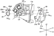
Fig. 1 is a schematic view of a vehicle door to which a door lock device according to an embodiment of the present invention is applied (a view seen from the right side of the vehicle).
Fig. 2 is a perspective view of the door lock device as viewed from the inside of the vehicle compartment (left front and obliquely downward).
Fig. 3A is a perspective view of the door lock device as viewed from the inside of the vehicle compartment (left front and obliquely above).
Fig. 3B is a front view of the door-lock apparatus viewed from the front side.
Fig. 4 is a front view of the housing as viewed from the front side.
Fig. 5 is a perspective view showing an installation process of the latch.
Fig. 6 is a perspective view of the latch lever.
Fig. 7A is a front view of the bus bar as viewed from the front side.
Fig. 7B is a perspective view of the bus bar.
Fig. 8 is a cross-sectional view showing a three-dimensional intersection of bus bars.
Fig. 9 is a perspective view showing a switch mounting process.
Fig. 10A is a front view showing the postures of the latch, the claw and the lift lever in the state where the door is opened, and the on/off states of the latch switch and the claw switch.
Fig. 10B is a front view showing the postures of the latch, the claw and the lift lever in a state where the vehicle door is slightly closed from fig. 10A, and the on/off states of the latch switch and the claw switch.
Fig. 10C is a front view showing the positions of the latch, the claw and the lift lever, and the on/off states of the latch switch and the claw switch in a state immediately before the half door state is reached from the slightly closed door of fig. 10B.
Fig. 10D is a front view showing the postures of the latch, the claw and the lift lever in the half-door state, and the on/off states of the latch switch and the claw switch.
Fig. 10E is a front view showing the postures of the latch, the claw and the lift lever in the state where the vehicle door is slightly closed from fig. 10D, and the on/off states of the latch switch and the claw switch.
Fig. 10F is a front view showing the postures of the latch, the claw and the lift lever in the state where the vehicle door is slightly closed from fig. 10E, and the on/off states of the latch switch and the claw switch.
Fig. 10G is a front view showing the positions of the latch, the pawl, and the lift lever, and the on/off states of the latch switch and the pawl switch in a state immediately before the vehicle door is slightly closed and reaches the fully closed state from fig. 10F.
Fig. 10H is a front view showing the positions of the latch, the pawl, and the lift lever, and the on/off states of the latch switch and the pawl switch in a state immediately before the vehicle door is slightly closed and reaches the fully closed state from fig. 10G.
Fig. 11A is a front view showing a posture of an open lever in a state where a door handle is not pulled, and an on/off state of a handle switch.
Fig. 11B is a front view showing a posture of the open lever in a state where the door handle is pulled, and an on/off state of the handle switch.
Description of reference numerals
1 … latch device (door lock device for vehicle), 10 … housing, 11 … latch body, 12 … bus bar, 20 … latch, 21 … body portion, 21b … half latch claw, 21c … full latch claw, 22 … latch switch lever, 30 … claw, 40 … lift lever, 50 … open lever, 60 … switch, 61 … latch switch, 61a … temporary stop switch, 61b … half/full switch, 62 … claw switch, 63 … handle switch, AC … actuator, CH … connector housing, CP … contact pin, DF … door frame, DL … door lock device, DP … door panel, DR … door, GL … ground wire, HFL … half/full switch wire, HL … handle switch wire, LS … latch shaft, PS … pawl shaft, SG … striker, SR … striker entrance slot, ST 9634 striker entrance slot, ST … striker
Detailed Description
A vehicle door lock device 1 (hereinafter, simply referred to as a latch device 1) according to an embodiment of the present invention will be described below. First, an outline of the door DR to which the latch device 1 is applied will be described (see fig. 1). The door DR is attached to an entrance provided in a side surface portion of the vehicle body. In addition, although the present embodiment is an example in which the present invention is implemented as the latch device 1 of the right door DR, the present invention can be applied to other doors.
The door DR includes a door panel DP and a door frame DF. The door panel DP is composed of an outer panel DPa (cabin outer panel) and an inner panel DPb (cabin inner panel). The outer peripheral edges of the outer panel DPa and the inner panel DPb are joined to each other. The outer panel DPa and the inner panel DPb are press-molded in advance so as to form a space therebetween in a state where the outer peripheral edges of the outer panel DPa and the inner panel DPb are joined to each other. That is, the door panel DP has a box shape (or a bag shape). A door frame DF is attached to an upper portion of the door panel DP as a window frame.
The front end surface of the door panel DP is assembled to the inner peripheral portion of the entrance via a hinge not shown. The door panel DP is rotated around the axis of the hinge to open and close the door panel DP. In the following description, the thickness direction of the door DR is referred to as the X direction (see fig. 2, 5, 10A, and the like). The vehicle height direction is referred to as the Z direction. The direction perpendicular to the X direction and perpendicular to the Z direction is referred to as the Y direction. In each figure, "+ X" corresponds to the outside of the vehicle compartment, and "— X" corresponds to the inside of the vehicle compartment. In addition, "+ Y" corresponds to the front, and "-Y" corresponds to the rear. "+ Z" corresponds to the upper side, and "-Z" corresponds to the lower side.
A door handle device DH and a door lock device DL are attached to the door panel DP.
The door handle device DH is mounted to the rear of the door panel DP. The door handle device DH includes a handle DHa supported to be rotatable about a predetermined axis. The handle DHa protrudes outward from an opening provided in the outer panel DPa. The door handle device DH includes a plurality of levers (cranks), not shown, that are housed in a space between the inner panel DPb and the outer panel DPa. One of the levers is connected to a door lock device DL (an opening lever 50) described later via a lever RD.
The door lock device DL is disposed at the rear portion inside the door panel DP. As shown in fig. 2, the door lock device DL includes a lock/unlock device LR, a latch device 1, and an actuator AC.
The locking/unlocking device LR includes a plurality of levers, cams, links, and the like for switching between a locked state in which the door DR cannot be opened and closed and an unlocked state in which the door DR can be opened and closed. In fig. 2, the components of the locking/unlocking device LR are not shown. The locking/unlocking device LR has no direct relation to the present invention, and therefore, the detailed configuration and operation thereof will not be described.
Next, a brief description of the latch device 1 will be given. The latch device 1 engages with a striker ST (see fig. 1) provided on an inner peripheral portion of an entrance of a vehicle to maintain a state where a door DR is closed (fully closed state). The latch device 1 includes a plurality of levers (a latch 20, a pawl 30, a lift lever 40, and an open lever 50 described later) (see fig. 3A, 10A, and the like). The lever is supported to be rotatable about an axis extending in the Y direction.
An opening provided in the rear end surface of the door panel DP communicates with a part of the latch device 1 (a striker entrance path SR described later). During the process of closing the door DR, the striker ST enters the door panel DP from the opening portion, and the latch device 1 engages with the striker ST. That is, the levers constituting the latch device 1 rotate (see fig. 10A to 10H). The latch device 1 includes a plurality of switches 60 (a latch switch 61, a claw switch 62, and a handle switch 63 described later) for detecting the rotational positions of the various levers. The switches are arranged along the outer periphery of the rotational locus of each lever, and their on/off states change depending on the rotational position of the lever.
Next, a specific structure of the latch device 1 will be described. The latch device 1 includes a housing 10 (see fig. 3A and 3B), a latch 20, a pawl 30, a lift lever 40, an open lever 50, and a switch 60 (see fig. 3A, 3B, 10A, and 11A).
The housing 10 includes a latch body 11 as a housing for supporting (housing) other components of the latch device 1, and a bus bar 12 (see fig. 4) as a transmission path of a signal indicating an on/off state of various switches described later.
First, the structure of the main portion of the latch body 11 in the structure of the housing 10 will be described below. Next, the structure of the latch 20, the pawl 30, the lift lever 40, the open lever 50, and the switch 60 will be described, and then the structure of the bus bar 12 of the housing 10 will be described.
The latch body 11 is made of synthetic resin. The latch body 11 has a base 11 a. The housing 10 is fixed to the rear portion of the door DR such that the thickness direction of the base 11a coincides with the Y direction. That is, one side surface (front surface S1) of the base 11a faces forward (+ Y direction), and the other side surface (rear surface S2) faces rearward (-Y direction) (see fig. 3A). In the process of closing the door DR, the striker ST enters the door panel DP through an opening portion provided at the rear portion of the door DR. The striker ST enters the latch body 11. The base 11a is provided with a groove-shaped striker entrance path SR (see fig. 3A) that opens rearward and extends in the X direction. A connector housing CH constituting a connector C to which a harness, not shown, is connected is provided at a lower end portion of the latch body 11.
Further, a latch shaft LS (see fig. 3B) is provided in a region a (see fig. 4) of the base 11a located above the striker entrance path SR. The front half of the latch shaft LS projects forward (corresponding to the front surface side in fig. 3B) from the front surface S1 of the base 11a, and the rear half of the latch shaft LS projects rearward (corresponding to the rear surface side in fig. 3B) from the rear surface S2 of the base 11 a.
Further, a pawl shaft PS is provided in a region B of the base 11a located below the striker entrance path SR. The front half of the pawl shaft PS projects forward from the front surface S1 of the base 11a, and the rear half of the pawl shaft PS projects rearward from the rear surface S2 of the base 11 a.
Further, an open lever shaft OS is provided in a portion of the region B located below the pawl shaft PS. The opening lever shaft OS projects forward from the front surface S1 of the base 11 a.
The latch 20 includes a main body 21 and a latch switch lever 22 (see fig. 5). The main body 21 is a substantially plate-like member. The body portion 21 is disposed in parallel to the Y direction in the plate thickness direction. The body portion 21 includes a base portion 21a, a half locking claw 21b extending in substantially the same direction from the base portion 21a, and a full locking claw 21 c. The base 21a is provided with a through hole TH21a. The half locking claws 21b are separated from the full locking claws 21c in a direction perpendicular to the direction in which they are arranged. In the following description, a space between the half locking claw 21b and the full locking claw 21c is referred to as a striker groove SG. The latch 20 is biased counterclockwise in fig. 10A toward the initial position (return position) by a torsion spring (not shown).
The main body 21 includes a pin 21d protruding from one side surface of the base 11 a. The latch switch lever 22 described below engages with the pin 21d, and the main body 21 and the latch switch lever 22 rotate integrally about the latch axis LS.
The latch switch lever 22 includes a base portion 22a and a switch pressing portion 22b (see fig. 6). The base portion 22a is a plate-like portion extending in the radial direction of the latch axis LS. The plate thickness direction of the base portion 22a is parallel to the Y direction. The base portion 22a has a through hole TH22a. A switch pressing portion 22b is provided at the distal end of the base portion 22 a. The switch pressing portion 22b is a curved portion (arc-shaped portion) extending in the circumferential direction of the latch shaft LS. The switch pressing portion 22b is constituted by the first pressing portion 22b1 and the second pressing portion 22b 2. The first pressing portion 22b1 and the second pressing portion 22b2 are offset in the Y direction. The first pressing portion 22b1 is located forward of the second pressing portion 22b 2. Outer peripheral surface S of the first pressing portion 22b122b1And the outer peripheral surface S of the second pressing portion 22b222b2Is a circular arc surface with an outer peripheral surface S22b1Specific peripheral surface S22b2Near the through hole TH22aOf the center of (c). The latch switch lever 22 has a hole H into which the pin 21d is inserted22。
The body part 21 is brought close to the base 11a from the rear surface S2 side of the base 11a, and the latch shaft is movedThe back half part of LS is inserted into the through hole TH21a(refer to fig. 5). The base 11a is provided with an approximately arc-shaped opening OP11aThe pin 21d passes through the opening OP11aTo the front side S1 side. The latch switch lever 22 is brought close to the base 11a from the front surface S1 side of the base 11a, and the front half of the latch shaft LS is inserted into the through hole TH22aAnd the pin 21d is inserted into the hole H22. Thus, the main body 21 is rotatably supported by the latch shaft LS on the rear surface S2 side of the base 11a, and the latch switch lever 22 is rotatably supported by the latch shaft LS on the front surface S1 side of the base 11 a. The main body 21 and the latch switch lever 22 are coupled via a pin 21d, and both integrally rotate about the latch axis LS. The latch 20 is biased to rotate counterclockwise in fig. 10A by a torsion spring, not shown, and a predetermined portion of the body 21 abuts against the stopper to stop the latch 20.
The structure of the jaw 30 is the same as that of the known door lock apparatus. That is, the claw 30 is supported by the rear half of the claw shaft PS. That is, the pawl 30 is disposed on the rear surface S2 side of the base 11a (below the body portion 21 of the latch 20). The pawl 30 is biased clockwise in fig. 10A toward the initial position (return position) by a torsion spring (not shown). The pawl 30 engages with the body 21 of the latch 20 to restrict the rotation of the body 21.
The construction of the lifting lever 40 is also the same as that of known latching devices. The lift lever 40 is supported by the front half of the jaw shaft PS. That is, the lift lever 40 is disposed on the front surface S1 side of the base 11 a. The latch 30 and the lift lever 40 are rotatably supported by a latch shaft PS, and the latch shaft PS is rotatably supported by the base 11 a. Thus, the jaws 30 rotate integrally with the lift lever 40.
The opening lever 50 is supported by an opening lever shaft OS (see fig. 3B and 11A). That is, the opening lever 50 is disposed on the front surface S1 side of the base 11 a. The opening lever 50 is located below the lifting lever 40. The opening lever 50 is biased clockwise in fig. 11A toward the initial position (return position) by a torsion spring (not shown). As is well known, the opening lever 50 is connected to the handle DHa of the door handle DH via a link mechanism (lever RD). The opening lever 50 is pulled by the handle DHa (door opening operation), and thereby rotates against the urging force of the torsion spring, and the claw 30 is rotated via the lift lever 40, and the engagement between the body portion 21 of the latch 20 and the claw 30 is released.
The switch 60 is composed of a latch switch 61 (a temporary stop switch 61a and a full on/off switch 61B), a claw switch 62, and a handle switch 63 (see fig. 3B). The switch is disposed on the front surface S1 side of the base 11 a. The switch is a push button switch. The latch switch 61 is in a state in which two internal contacts are electrically connected (short-circuited) when the push button is pressed, and in a state in which the two contacts are released when the push button is released. On the other hand, the click switch 62 and the handle switch 63 are in a state in which two internal contacts are released when the button is pressed, and in a state in which the two contacts are conductive (short-circuited) when the button is released. Each switch includes a terminal TS electrically connected to the two contacts.
The latch switch 61 is composed of a temporary stop switch 61a and a full on/off switch 61 b. The temporary stop switch 61a and the full on/off switch 61b are disposed along the outer periphery of the rotation trajectory of the latch switch lever 22. The push buttons of the two switches face the center side of the latch shaft LS. The half/full switch 61b and the temporary stop switch 61a are displaced in the rotational direction of the latch switch lever 22. Specifically, the temporary stop switch 61a and the full on/off switch 61B are arranged diagonally left and upward as viewed from the latch axis LS in fig. 3B. The full/half switch 61b is disposed at a position slightly advanced in the clockwise direction as viewed from the pause switch 61 a. The temporary stop switch 61a and the full on/off switch 61b are shifted in the Y direction so as to correspond to the first pressing portion 22b1 and the second pressing portion 22b2 of the latch switch lever 22, respectively. Specifically, the full on/off switch 61b is disposed slightly behind the temporary stop switch 61 a.
The claw switch 62 is configured to follow the outer periphery of the rotation locus of the lift lever 40. In fig. 3B, the jaw switch 62 is disposed on the left side (outer plate DPa side) as viewed from the jaw axis PS. The push button of the latch switch 62 faces downward (obliquely downward to the right in fig. 3B) from the center of the latch axis PS. A thin plate spring BS is provided between the lift lever 40 and the push button of the claw switch 62, and the push button of the claw switch 62 is pressed by the lift lever 40 via the plate spring BS (see fig. 10A to 10H).
The handle switch 63 is disposed along the outer periphery of the turning locus of the opening lever 50. The handle switch 63 is disposed obliquely downward to the left as viewed from the open lever axis OS in fig. 3B. The knob of the handle switch 63 is oriented rightward (toward the inner plate DPb) in fig. 3B.
Switch storage portions SH for storing the switches are provided on the front surface S1 of the base 11a61a、SH6、SH62、SH63。
The bus bar 12 is formed of a plurality of (5 in the present embodiment) elongated thin plate-like metal pieces (a ground line GL, a half/full switch line HFL, a temporary stop switch line TL, a claw switch line PL, and a handle switch line HL) (see fig. 7A and 7B). One end of each wire functions as a contact pin CP, and the other end functions as a terminal TB connected to various switches. One end of each wire is arranged at equal intervals in the X direction in the connector housing CH. Specifically, in the connector housing CH, the ground line GL, the handle switch line HL, the temporary stop switch line TL, the full/half switch line HFL, and the claw switch line PL are arranged in this order from one side (the outer panel DPa side) in the X direction toward the other end (the inner panel DPb side) as viewed from the ground line GL. The wires extend upward from the connector housing CH, and the other ends thereof are located in the switch receiving portions (see fig. 4). However, the wires are bent at their intermediate portions in order to avoid other components. The ground line GL is commonly used in the switches. That is, the ground line GL has a short sub-line branched from the middle portion thereof, and the end portion of the sub-line is positioned in each switch housing portion, and this portion functions as the terminal TB. Further, a portion near one end of the ground line GL is formed to be curved so as to protrude forward (in the + Y direction), and the grip switch line HL, the full/half switch line HFL, and the temporary stop switch line TL pass rearward of this portion. That is, various lines intersect each other at this portion (see fig. 7A, 7B, and 8).
The latch body 11 and the bus bar 12 are integrally formed by insert molding. That is, the portions excluding the contact pins CP and the terminal TB of the wires constituting the bus bar 12 are embedded in the latch body 11. In other words, the contact pin CP is exposed in the connector housing CH with the terminal TB openClosing storage part SH61a、SH61b、SH62、SH63Is exposed inside. The housing 10 is formed by inserting the temporary stop switch 61a, the half/full switch 61b, the claw switch 62, and the handle switch 63 into the switch housing part SH thereof61a、SH61b、SH62、SH63The terminal TB is electrically connected to the terminal TS of each switch (see fig. 9). For example, the terminal TS of the switch is a plate spring-like member, and the terminal TS and the terminal TB are crimped by using the elastic force thereof. Then, a synthetic resin material is flowed into a connection portion between the terminal TS and the terminal TB of the switch and is cured. This covers the joint between the terminal TS and the terminal TB, and electrically insulates this part. This prevents foreign matter (water droplets, dust, etc.) from adhering to the portions and shorting the terminals TS to each other.
The unillustrated harness has one end connected to the connector C and the other end connected to a vehicle control device. The control device detects the on/off state of each switch.
The actuator AC (see fig. 2) includes an electric motor, a reduction gear, and the like. The rotational driving force of the electric motor is transmitted to the latch 20 via the reduction gear, and the latch 20 is rotationally driven. The electric motor is connected to a vehicle control device (power supply device) using a wire harness (not shown). As described later, the control device controls the rotation speed, rotation direction, and the like of the electric motor based on the on/off state of the switch detected as described above.
Next, the operations of the latch 20, the pawl 30, and the lift lever 40, and the operations (on/off states) of the latch switch 61 (the temporary stop switch 61a and the full/half switch 61b) and the pawl switch 62 in the process from the state in which the door DR is opened to the state in which the door DR is closed will be described. In a state where the door DR is opened, the front end portion of the striker groove SG between the half-locking claw 21b and the full-locking claw 21c of the body portion 21 of the latch 20 is located in the striker entry path SR. In this state, the switch pressing portion 22b of the latch switch lever 22 is directed substantially leftward in fig. 10A, and the first pressing portion 22b1 presses the button of the temporary stop switch 61a, thereby turning the temporary stop switch 61a on (see fig. 10A). On the other hand, the second pressing portion 22b2 is separated from the push button of the full/half switch 61b, and the full/half switch 61b is turned off. Further, the tip (left end in fig. 10A) of the pawl 30 abuts against the outer peripheral surface portion of the half locking pawl 21 b. Further, the push button of the click switch 62 is pressed by the lift lever 40, and the click switch 62 is turned off.
During the process that the door DR is closed, the striker ST entered into the door panel DP enters the striker groove SG of the latch 20 (refer to fig. 10A). The main body 21 is pressed by the striker ST and starts to rotate clockwise in fig. 10A. When the striker ST slightly enters the latch device 1 from the state shown in fig. 10A (the state in which the door DR is opened), the latch 20 slightly rotates clockwise in fig. 10A, and reaches the state shown in fig. 10B. In this state, the push button of the temporary stop switch 61a is still pressed by the first pressing portion 22b1, and the temporary stop switch 61a is turned on. Further, the second pressing portion 22b2 remains separated from the push button of the full/half switch 61b, and the full/half switch 61b is turned off. Further, the tip of the claw 30 is pressed by the half locking claw 21b of the body 21, and is slightly rotated counterclockwise from the state shown in fig. 10A. The lift lever 40 also rotates in the same manner as the latch 30, the push button of the latch switch 62 is released, and the latch switch 62 is turned on. That is, in the process from fig. 10A to fig. 10B, the dog switch 62 changes from the off state to the on state.
When the striker ST enters the latch device 1 further from the state shown in fig. 10B, the latch 20 slightly rotates clockwise in fig. 10B, and reaches the state shown in fig. 10C. In this state, the second pressing portion 22b2 of the latch switch lever 22 presses the push button of the full/half switch 61b, and the full/half switch 61b is turned on. The button of the temporary stop switch 61a is still pressed by the first pressing portion 22b1, and the temporary stop switch 61a is turned on. Further, the tip of the claw 30 is pressed by the half locking claw 21B of the body 21, and is further turned counterclockwise from the state shown in fig. 10B. The lifting rod 40 also rotates in the same way as the jaws 30. The push button of the click switch 62 is still released, and the click switch 62 becomes on state. That is, in the process from fig. 10B to fig. 10C, the full/half switch 61B changes from the off state to the on state.
When the striker ST enters the latch device 1 further from the state shown in fig. 10C, the latch 20 slightly rotates clockwise in fig. 10C, and reaches the state shown in fig. 10D. In this state, the on/off states of the temporary stop switch 61a and the full on/off switch 61b are the same as those shown in fig. 10C. Further, the half locking claw 21b goes beyond the tip of the claw 30, and the claw 30 rotates clockwise from the state shown in fig. 10C, returns to the initial state, and abuts against the half locking claw 21 b. Thus, in fig. 10C, the body 21 is restricted from rotating counterclockwise. The lift lever 40 returns to the initial state similarly to the latch 30, and the latch switch 62 is turned off by the push button of the latch switch 62 being pressed by the lift lever 40. That is, in the process from fig. 10C to fig. 10D, the dog switch 62 changes from the on state to the off state.
When the striker ST enters the latch device 1 further from the state shown in fig. 10D, the latch 20 slightly rotates clockwise in fig. 10D, and reaches the state shown in fig. 10E. In this state, the first pressing portion 22b1 is separated from the button of the temporary stop switch 61a, and the temporary stop switch 61a is turned off. On the other hand, the push button of the full/half switch 61b is still pressed by the second pressing portion 22b2, and the full/half switch 61b is turned on. The front end of the claw 30 is separated from the body 21, the postures of the claw 30 and the lift lever 40 are maintained in the initial state, and the claw switch 62 is maintained in the on state. That is, in the process from fig. 10D to fig. 10E, the temporary stop switch 61a changes from the on state to the off state.
When the striker ST enters the latch device 1 further from the state shown in fig. 10E, the latch 20 slightly rotates clockwise in fig. 10E, and reaches the state shown in fig. 10F. In this state, the on/off states of the temporary stop switch 61a and the full on/off switch 61b are the same as those of fig. 10E. Further, the tip of the claw 30 is pressed by the full lock claw 21c of the body 21, and is slightly rotated counterclockwise from the state shown in fig. 10E. The lift lever 40 also rotates in the same manner as the latch 30, the push button of the latch switch 62 is released, and the latch switch 62 is turned on. That is, in the process from fig. 10E to fig. 10F, the dog switch 62 changes from the off state to the on state.
When the striker ST enters the latch device 1 further from the state shown in fig. 10F, the latch 20 slightly rotates clockwise in fig. 10F, and reaches the state shown in fig. 10G. In this state, the second pressing portion 22b2 is separated from the push button of the full/half switch 61b, and the full/half switch 61b is turned off. Further, the tip of the claw 30 is pressed by the full lock claw 21c of the body 21, and is further rotated counterclockwise from the state shown in fig. 10F. The lift lever 40 is also rotated in the same manner as the latch 30, the push button of the latch switch 62 is kept released, and the latch switch 62 is kept on. That is, in the process from fig. 10F to fig. 10G, the full/half switch 61b changes from the on state to the off state.
When the striker ST enters the latch device 1 further from the state shown in fig. 10G, the latch 20 slightly rotates clockwise in fig. 10FG, and reaches the state shown in fig. 10H. In this state, the on/off states of the temporary stop switch 61a and the full on/off switch 61b are the same as those in fig. 10G. Further, the full lock claw 21c moves over the tip of the claw 30, the claw 40 rotates clockwise from the state shown in fig. 10G, returns to the initial state, and abuts against the full lock claw 21c, and the rotation of the body portion 21 in the counterclockwise direction is restricted in fig. 10H. The lift lever 40 returns to the initial state similarly to the latch 30, and the latch switch 62 is turned off by the push button of the latch switch 62 being pressed by the lift lever 40. That is, in the process from fig. 10G to fig. 10H, the dog switch 62 changes from the on state to the off state.
Next, the operation of the opening lever 50 and the operation of the handle switch 63 will be described. In a state where the handle DHa is not pulled, the button of the handle switch 63 is pressed by the open lever 50, and becomes an off state. When the handle DHa is pulled outward, the lever RD of the door handle device DH is pushed downward by rotating the lever in a predetermined direction in conjunction with the handle DHa. The opening lever 50 connected to the lever RD is rotated counterclockwise in fig. 11A, and the state shown in fig. 11B is reached. In this state, the knob of the handle switch 63 is released, and the handle switch 63 is turned on.
The control device of the vehicle controls the actuator AC (electric motor) based on the transition of the combination of the on/off states of the temporary stop switch 61a, the half/full switch 61b, the dog switch 62, and the handle switch 63. Specifically, when the control device detects that the handle switch 63 is in the off state and the pause switch 61a, the full on/off switch 61b, and the claw switch 62 are shifted from the state shown in fig. 10C to the state shown in fig. 10D, the time is measured quickly using the timer. When a predetermined time (for example, 3 seconds) has elapsed in the state of fig. 10D, the control device operates the actuator AC (rotates the electric motor forward), and rotates the latch 20 clockwise in fig. 10D. When detecting that the pause switch 61a, the full/full switch 61b, and the claw switch 62 have shifted from the state shown in fig. 10D to the state shown in fig. 10E, the control device pauses the actuator AC and starts time measurement using a timer. When a predetermined time (for example, 1 second) has elapsed since the temporary stop of the actuator AC, the control device operates the actuator AC again to rotate the latch 20 clockwise in fig. 10E. Then, when detecting that the temporary stop switch 61a, the half/full switch 61b, and the dog switch 62 transit the states shown in fig. 10E to 10F, and 10G and transit to the state shown in fig. 10H, the control device stops the actuator AC. In this way, the control device causes the door DR, which is the half-door-kept state, to transition to the fully closed state. However, when the handle switch 63 is in the on state, the control device does not operate the actuator AC. When the control device detects only the transition from the off state to the on state during the operation of the actuator AC, the control device stops the actuator AC even in the middle of the transition from the half-door state to the fully closed state.
Here, for example, in the case of a configuration in which the turning angle position of the latch 20 or the pawl 30 is detected using a rotary switch disposed coaxially with respect to the rotation axis of the latch 20 or the pawl 30, the size of the entire vehicle door lock device (particularly, the size in the direction parallel to the extending direction of the rotation axis of the latch 20 or the pawl 30) tends to increase. In contrast, in the latch device 1 of the present embodiment, the push button type latch switch 61 and the claw switch 62 are disposed along the outer peripheries of the turning trajectories of the latch 20 and the claw 30. This enables the size (particularly, the size in the Y direction) of the latch device 1 to be set to be small.
In the latch device 1 of the present embodiment, the latch switch 61 is disposed in the first region a, and the claw switch 62 is disposed in the second region B. Accordingly, as compared with the case where the latch switch 61 and the claw switch 62 are biased to one side (the first region a) or the other side (the second region B) of the striker entry path SR, the space in each of the first region a and the second region B can be effectively used, and the size (particularly, the size in the X direction and the Z direction) of the latch device 1 can be set to be small.
For example, when the latch switch 61 is disposed in the second region B, the latch switch lever 22 needs to be extended below the striker entry path SR while avoiding the striker entry path SR. In this case, the dimension of the latch device 1 in the Y direction is larger than that of the above embodiment. In contrast, in the present embodiment, the latch switch 61 is disposed in the same first region a as the latch 20 (latch switch lever 22), and the latch switch lever 22 is relatively small, so that the size of the latch device 1 (particularly, the size in the X direction, the Y direction, and the Z direction) can be set small.
In the above embodiment, the ground lines GL are not provided for each switch, and one ground line GL and some other signal lines are allowed to intersect each other in a three-dimensional manner, so that all switches share the ground line GL. Thus, the number of pins of the connector C can be restricted to a minimum, and the space for arranging the bus bar 12 can be restricted to a minimum, as compared with the case where the ground lines GL are provided in units of switches. This makes it possible to set the dimensions of the latch device 1 (particularly, the dimensions in the X, Y, and Z directions) to be small.
Here, for example, when a switch member in which a switch is assembled in advance to a wire harness is used instead of the bus bar 12 and the switch 60 in the above embodiment, the number of wiring steps for the wire harness is large. In contrast, in the present embodiment, the bus bar 12 is embedded in the latch body 11, and each switch is attached to the terminal TB. Thus, according to the present embodiment, the switch 60 can be easily attached to the latch body 11.
The present invention is not limited to the above embodiments, and various changes can be made without departing from the object of the present invention.
For example, in the above embodiment, in the configuration of the bus bar 12, one ground line GL is used in common for all the switches, but one ground line GL may be used in common for at least two switches.
Claims (5)
1. A door lock device for a vehicle, which is disposed in a predetermined space in a door and maintains a state where the door is closed, comprising:
a latch which is supported to be rotatable about a first shaft extending in a predetermined direction, abuts against a striker which enters the door when the door is closed, rotates in a first direction about the first shaft, and is locked to the striker;
a pawl supported rotatably about a second axis parallel to the first axis and configured to restrict rotation of the latch locked to the striker, that is, to restrict rotation of the latch locked to the striker in a second direction opposite to the first direction;
a latch switch for detecting a rotational angle position of the latch;
a claw switch for detecting the rotation angle position of the claw; and
a bus bar connected to terminals of the latch switch and the claw switch and serving as a transmission path of an electric signal indicating on/off states of the latch switch and the claw switch,
the first shaft and the second shaft are respectively arranged in a first area on one side and a second area on the other side of an inlet path of the striker,
the latch switch is configured to be arranged outside the first region in the rotation radius direction of the latch, the on/off state of the latch switch changes according to the rotation angle position of the latch,
the claw switch is configured to be arranged outside the second area in the direction of the rotation radius of the claw, the on/off state of the claw switch is changed according to the rotation angle position of the claw,
one end of the bus bar is arranged at a predetermined position of the second region and constitutes a contact pin.
2. The door lock device for a vehicle according to claim 1, further comprising:
a base made of synthetic resin for supporting the first shaft and the second shaft,
the portion of the bus bar excluding the end portion is embedded in the base portion.
3. The vehicular door lock device according to claim 1 or 2,
the bus bar is composed of a plurality of metal sheets each formed in a long shape,
at least two of the plurality of metal sheets intersect each other at their intermediate portions.
4. The door lock device for a vehicle according to claim 1, further comprising:
a latch switch lever that rotates in conjunction with the rotation of the latch switch,
the on/off state of the latch switch is configured to be changed according to the rotation angle position of the latch switch lever.
5. The door lock device for a vehicle according to claim 1, further comprising:
a lifting rod which is engaged with the claw to rotate the claw,
the on/off state of the claw switch is changed according to the rotation angle position of the lifting rod.
Applications Claiming Priority (2)
| Application Number | Priority Date | Filing Date | Title |
|---|---|---|---|
| JP2020017654A JP7419847B2 (en) | 2020-02-05 | 2020-02-05 | Vehicle door latch device and its manufacturing method |
| JP2020-017654 | 2020-08-24 |
Publications (1)
| Publication Number | Publication Date |
|---|---|
| CN215212876U true CN215212876U (en) | 2021-12-17 |
Family
ID=77458470
Family Applications (1)
| Application Number | Title | Priority Date | Filing Date |
|---|---|---|---|
| CN202120310012.XU Active CN215212876U (en) | 2020-02-05 | 2021-02-03 | Door lock device for vehicle |
Country Status (2)
| Country | Link |
|---|---|
| JP (1) | JP7419847B2 (en) |
| CN (1) | CN215212876U (en) |
Family Cites Families (4)
| Publication number | Priority date | Publication date | Assignee | Title |
|---|---|---|---|---|
| JP4327539B2 (en) | 2003-09-18 | 2009-09-09 | 株式会社大井製作所 | Closing drive device for opening and closing body |
| JP5978484B2 (en) | 2011-08-31 | 2016-08-24 | 三井金属アクト株式会社 | Vehicle door latch device |
| JP6454907B2 (en) | 2014-07-18 | 2019-01-23 | 三井金属アクト株式会社 | Vehicle door latch device |
| CN107429525B (en) | 2015-03-10 | 2019-09-03 | Gecom公司 | Door latch apparatus |
-
2020
- 2020-02-05 JP JP2020017654A patent/JP7419847B2/en active Active
-
2021
- 2021-02-03 CN CN202120310012.XU patent/CN215212876U/en active Active
Also Published As
| Publication number | Publication date |
|---|---|
| JP7419847B2 (en) | 2024-01-23 |
| JP2021123937A (en) | 2021-08-30 |
Similar Documents
| Publication | Publication Date | Title |
|---|---|---|
| EP3260636B1 (en) | Automobile door latch apparatus | |
| US20020063430A1 (en) | Door lock drive unit | |
| US8485571B2 (en) | Door lock apparatus for vehicle | |
| CN103075054A (en) | Vehicle door latch device | |
| WO2005089278A2 (en) | Latch apparatus and method | |
| US7029054B2 (en) | Outside handle device | |
| CN110219525A (en) | Method for the closure latch assembly of car door and for activating the latch assembly | |
| US20140175809A1 (en) | Closure mechanism for vehicle door | |
| US7461873B2 (en) | Actuator and vehicle-mounted electrically operated device having the same | |
| US20180023326A1 (en) | Automobile door latch apparatus | |
| US20170335605A1 (en) | Vehicle door lock device | |
| JP4015568B2 (en) | Outside handle device and connector structure thereof | |
| CN215212876U (en) | Door lock device for vehicle | |
| KR20140096188A (en) | Door opening and closing device for car | |
| US11365567B2 (en) | Power child lock system for vehicle | |
| JPH1178527A (en) | Lock device for slide door in vehicle | |
| CN105986710B (en) | Door lock device | |
| CN112392341B (en) | Electric children lock device | |
| CN220621478U (en) | Lock for motor vehicle | |
| KR101209607B1 (en) | Apparatus for preventing clash of sliding door and fuel filler door in vehicle | |
| CN216277402U (en) | Electric opening mechanism of automobile door lock | |
| KR100527938B1 (en) | Trunk rid lamp switch structure of automobile | |
| CN113982385B (en) | Electric unlocking mechanism of automobile door lock | |
| KR20040016737A (en) | Safety locking apparatus for power sliding door of vehicle | |
| CN113982385A (en) | Electric opening mechanism of automobile door lock |
Legal Events
| Date | Code | Title | Description |
|---|---|---|---|
| GR01 | Patent grant | ||
| GR01 | Patent grant |