EP1443128A1 - Machine de service de cellules d'électrolyse pour la production d'aluminium - Google Patents
Machine de service de cellules d'électrolyse pour la production d'aluminium Download PDFInfo
- Publication number
- EP1443128A1 EP1443128A1 EP03356013A EP03356013A EP1443128A1 EP 1443128 A1 EP1443128 A1 EP 1443128A1 EP 03356013 A EP03356013 A EP 03356013A EP 03356013 A EP03356013 A EP 03356013A EP 1443128 A1 EP1443128 A1 EP 1443128A1
- Authority
- EP
- European Patent Office
- Prior art keywords
- rotary
- chassis
- rotation
- fixed
- sleeve
- Prior art date
- Legal status (The legal status is an assumption and is not a legal conclusion. Google has not performed a legal analysis and makes no representation as to the accuracy of the status listed.)
- Granted
Links
- XAGFODPZIPBFFR-UHFFFAOYSA-N aluminium Chemical compound [Al] XAGFODPZIPBFFR-UHFFFAOYSA-N 0.000 title claims abstract description 18
- 229910052782 aluminium Inorganic materials 0.000 title claims abstract description 17
- 238000004519 manufacturing process Methods 0.000 title claims abstract description 17
- 239000004411 aluminium Substances 0.000 title 1
- 238000005868 electrolysis reaction Methods 0.000 claims abstract description 43
- 239000004020 conductor Substances 0.000 claims description 23
- 238000009826 distribution Methods 0.000 claims description 14
- 230000000295 complement effect Effects 0.000 claims description 4
- 239000003792 electrolyte Substances 0.000 description 5
- 238000009626 Hall-Héroult process Methods 0.000 description 2
- PNEYBMLMFCGWSK-UHFFFAOYSA-N aluminium oxide Inorganic materials [O-2].[O-2].[O-2].[Al+3].[Al+3] PNEYBMLMFCGWSK-UHFFFAOYSA-N 0.000 description 2
- 229910001610 cryolite Inorganic materials 0.000 description 2
- 229910001338 liquidmetal Inorganic materials 0.000 description 2
- 235000020004 porter Nutrition 0.000 description 2
- 229910016569 AlF 3 Inorganic materials 0.000 description 1
- 229910000831 Steel Inorganic materials 0.000 description 1
- 238000007792 addition Methods 0.000 description 1
- 238000012550 audit Methods 0.000 description 1
- 239000003575 carbonaceous material Substances 0.000 description 1
- 238000006073 displacement reaction Methods 0.000 description 1
- 238000000605 extraction Methods 0.000 description 1
- 238000009434 installation Methods 0.000 description 1
- 239000011810 insulating material Substances 0.000 description 1
- 239000007788 liquid Substances 0.000 description 1
- 229910052751 metal Inorganic materials 0.000 description 1
- 239000002184 metal Substances 0.000 description 1
- 238000000034 method Methods 0.000 description 1
- 210000000056 organ Anatomy 0.000 description 1
- 239000011819 refractory material Substances 0.000 description 1
- 238000005096 rolling process Methods 0.000 description 1
- 239000007787 solid Substances 0.000 description 1
- 239000010959 steel Substances 0.000 description 1
Images


Classifications
-
- B—PERFORMING OPERATIONS; TRANSPORTING
- B66—HOISTING; LIFTING; HAULING
- B66C—CRANES; LOAD-ENGAGING ELEMENTS OR DEVICES FOR CRANES, CAPSTANS, WINCHES, OR TACKLES
- B66C17/00—Overhead travelling cranes comprising one or more substantially horizontal girders the ends of which are directly supported by wheels or rollers running on tracks carried by spaced supports
- B66C17/06—Overhead travelling cranes comprising one or more substantially horizontal girders the ends of which are directly supported by wheels or rollers running on tracks carried by spaced supports specially adapted for particular purposes, e.g. in foundries, forges; combined with auxiliary apparatus serving particular purposes
- B66C17/08—Overhead travelling cranes comprising one or more substantially horizontal girders the ends of which are directly supported by wheels or rollers running on tracks carried by spaced supports specially adapted for particular purposes, e.g. in foundries, forges; combined with auxiliary apparatus serving particular purposes for charging treatment chambers, e.g. furnaces, kilns, ovens
-
- C—CHEMISTRY; METALLURGY
- C25—ELECTROLYTIC OR ELECTROPHORETIC PROCESSES; APPARATUS THEREFOR
- C25C—PROCESSES FOR THE ELECTROLYTIC PRODUCTION, RECOVERY OR REFINING OF METALS; APPARATUS THEREFOR
- C25C3/00—Electrolytic production, recovery or refining of metals by electrolysis of melts
- C25C3/06—Electrolytic production, recovery or refining of metals by electrolysis of melts of aluminium
- C25C3/14—Devices for feeding or crust breaking
Definitions
- the invention relates to the production of aluminum by igneous electrolysis according to the Hall-Héroult process. It relates more particularly to service machines overhead crane used in said factories.
- Aluminum metal is produced industrially by igneous electrolysis, namely by electrolysis of alumina in solution in a molten cryolite bath, called bath electrolyte, according to the well-known Hall-Héroult process.
- the electrolyte bath is contained in cells, called “electrolysis cells", comprising a box in steel, which is coated internally with refractory and / or insulating materials, and a cathodic assembly located at the bottom of the tank. Carbon material anodes are partially submerged in the electrolyte bath.
- the unit formed by a tank electrolysis cell, its anodes and the electrolyte bath is called an electrolysis cell.
- the factories contain a large number of electrolysis cells arranged in line, in buildings called halls or electrolysis rooms, and electrically connected in series using connecting conductors, so as to optimize floor space factories.
- the cells are usually arranged so as to form two or several parallel lines which are electrically linked together by conductors end. The electrolysis current thus cascades from one cell to the next.
- an electrolysis plant requires interventions on the cells electrolysis which include, in particular, the replacement of anodes worn by new anodes, the removal of liquid metal from the cells and the electrolyte samples or additions.
- the factories more modern are equipped with one or more service units including a movable bridge which can be translated above the electrolysis cells, and along these, and a service module comprising a trolley and handling and intervention (often called “tools"), such as shovels and hoists, and able to be moved on the mobile bridge.
- tools often called "electrolysis service machines” or “M.S.E” (“PTA” or “Pot Tending Assembly “or” PTM “or” Pot Tending Machine "in English).
- the subject of the invention is a rotary mechanical and electrical connection device between a transport module, typically a trolley, and handling components and intervention of an aluminum production plant by igneous electrolysis, characterized in that it comprises a so-called “fixed” chassis provided with a straight hub or shaft, a sleeve surrounding the hub and able to rotate around it, a first and a second so-called “rotary” chassis able to rotate around the sleeve, contacts electric rotary sliding between the chassis and drive systems for cause the chassis to rotate relative to each other about an axis common.
- the two rotary chassis and the sleeve of the connection device of the invention are intended to rotate around a common axis of rotation, which is typically vertical in use, and independently of each other.
- the rotation of the chassis and sleeve is then called “coaxial".
- the sleeve is rotated by the first rotary chassis, typically by mechanical means, such as a finger.
- the connecting device according to the invention allows unlimited angular rotation between the three chassis, while ensuring a permanent electrical connection between them.
- the independence of chassis rotation increases the comfort and efficiency of the operator.
- FIG. 1 illustrates a typical electrolysis room, seen in section, intended for the production of aluminum and including a service unit represented so schematic.
- Figure 2 illustrates, schematically and in side view, a service module an aluminum production plant by igneous electrolysis according to the invention.
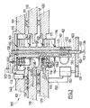
- FIG. 3 illustrates a connection device according to the invention, seen in section.
- Electrolysis plants for the production of aluminum include a liquid aluminum production area which includes one or more rooms electrolysis (1). As illustrated in Figure 1, each electrolysis room (1) has electrolysis cells (2) and at least one "service unit” or “machine for service "(3).
- the electrolysis cells (2) are normally arranged in rows or lines (typically side-by-side or head-to-head), each row or line comprising typically more than a hundred cells.
- Said cells (2) include a series of anodes (21) provided with a metal rod (22) intended for fixing and electrical connection of the anodes to a metallic anode frame (not shown).
- the service unit (3) is used to carry out operations on the cells (2) such as changing the anode or filling the feed hoppers with ground bath and AlF 3 of the electrolysis cells. It can also be used to handle various loads, such as tank elements, pockets of liquid metal or anodes.
- the service unit (3) comprises a movable bridge (4) which can be translated above electrolysis cells (2), and along them, and a service module (5) comprising a mobile carriage (6) capable of being moved on the mobile bridge (4) and several handling and intervention devices (7, 8, 9, 10, 11), such as tools (shovels, keys, biters, ...) and control booths.
- the movable bridge (4) rests and circulates on raceways (30, 30 ') arranged parallel to each other and to the main axis of the hall (and of the cell line). The movable bridge (4) can thus be moved along the electrolysis room (1).
- the hub (102) is locked in rotation relative to the fixed frame (101).
- the fixed chassis (101) is typically above the rotary chassis (110, 120).
- the axis of rotation (103) is normally substantially vertical.
- the first rotary frame (110) rotates with the sleeve (121) and drives it in rotation typically by mechanical means (123) such as a finger.
- Said pluralities of rotary sliding electrical contacts (113, 114) comprise typically rings or tracks attached to the sleeve (121) and brushes or wipers fixed to the chassis (101, 120).
- the number of sliding electrical contacts rotary is typically from a few tens to several tens. They allow including transferring control signals and electrical power.
- Said pluralities of electrical contacts (113, 114) are advantageously protected by a box (115, 116).
- the frames (101, 110, 120) typically include openings for passing said external and distribution conductors.
- Distribution conductors (118, 1181, 1182, 119) are conductors of the connection device which are likely to be driven by the rotation of the rotating frames (110, 120).
- Distribution conductors include a first series of conductors (118, 1181, 1182) which are normally fixed by relative to the sleeve (121) and to the first rotary frame (110), and a second series conductors (119) which are normally fixed relative to the second chassis rotary (120).
- the annular bearings (111, 112) are typically rolling bearings, such as roller crowns.
- connection device (100) advantageously comprises one or more assembly means for holding said frames (101, 110, 120) in a determined axial position.
- assembly means can be in whole or in part integrated into the annular bearings (111, 112).
- the drive systems (140, 141, 142, 150, 151, 152) include typically a motor (140, 150), a pinion (141, 151) and a ring gear (142) or a gear (152).
- the motor (140, 150) and the crown (142, 152) can be fixed respectively to the fixed frame (101) and to one of the rotating frames (110, 120), or vice versa.
- the motor (140, 150) can be fixed to the rotating chassis or fixed by mechanical means such as an arm (153).
- the drive systems may include one or more drive rollers by grip and at least one track.
- the connecting device (100) advantageously comprises annular bearings complementary (160, 161, 162, 163, 164) between the sleeve (121) and the fixed frame (101), possibly via the hub (102) - as illustrated in Figure 3 - And / or complementary annular bearings (170, 171) between the sleeve (121) and the second rotating frame (120). These additional bearings make it possible to avoid lateral displacements of the rotary elements (110, 120, 121).
- connection device comprises also rotary pneumatic and / or hydraulic connection means (130, 131, 132, 133) between the fixed chassis (101) and at least one of the rotary chassis (110, 120), and preferably both, and therefore for at least one of the turrets.
- These means of connection allow in particular a supply of compressed air to the organs of handling and intervention.
- These means advantageously include a cavity axial (130) in the central unit shaft (102), watertight rotary joints (131, 132) and additional pipes (133, 134).
- the first rotating frame (110) is located between the fixed frame (101) and the second rotating frame (120).
- the drive system of the second rotary frame (120) preferably comprises a toothed wheel (152) fixed to the hub (102) and a motor (150) fixed to the second rotary chassis (120) and provided with a pinion (151).
- the first turret (110 ') typically includes a control (11) and a hopper (10) containing the anode covering product.
- the second turret (120 ′) typically includes the various service tools for electrolytic cells, such as a stitching device (8) intended to break the crust alumina and cryolite which forms around and between the anodes, a shovel (7) intended for the removal of solid elements contained in an electrolysis cell at the time of an anode change and an anode handling system (9) intended for the extraction of spent anodes and for the installation of new anodes.
- the connecting device (100) is then typically placed so that the rotating frames (110, 120) are located below the fixed frame (101) when the carriage (6) is in the position of use on the overhead crane (4).
- the service module according to the invention allows the operator to have a large visibility on the electrolysis cell and on the tools or handling devices and intervention during his interventions. It also simplifies the task of the operator, in particular by avoiding significant angular rotations by compared to its original point. It also makes it possible to use the same module in separate electrolysis rooms in which the electrolysis cells are not oriented in the same way.
- the invention also relates to a service unit (3) of a production plant of aluminum by igneous electrolysis comprising an overhead crane (4) and at least one service module (5) according to the invention.
- the invention also relates to the use of a service module (5) or a service unit (3) according to the invention for interventions on cells electrolysis (2) intended for the production of aluminum by igneous electrolysis.
Landscapes
- Chemical & Material Sciences (AREA)
- Engineering & Computer Science (AREA)
- Chemical Kinetics & Catalysis (AREA)
- Electrochemistry (AREA)
- Materials Engineering (AREA)
- Metallurgy (AREA)
- Organic Chemistry (AREA)
- Mechanical Engineering (AREA)
- Electrolytic Production Of Metals (AREA)
- Electrolytic Production Of Non-Metals, Compounds, Apparatuses Therefor (AREA)
- Water Treatment By Electricity Or Magnetism (AREA)
Abstract
Description
- un châssis dit "fixe" comprenant un moyeu ou arbre dit "central" définissant un axe de rotation,
- un manchon entourant ledit moyeu et apte à tourner autour de celui-ci et autour dudit axe de rotation,
- un premier châssis dit "rotatif" tournant avec ledit manchon et apte à tourner autour de l'axe de rotation,
- un deuxième châssis dit "rotatif" apte à tourner autour dudit manchon et de l'axe de rotation,
- une première pluralité de contacts électriques glissants rotatifs dont un membre, destiné aux raccordements à des conducteurs extérieurs, est fixé au châssis fixe et l'autre membre, destiné aux raccordements à des conducteurs du système susceptibles d'être entraínés en rotation, est fixé au manchon,
- une deuxième pluralité de contacts électriques glissants rotatifs dont un membre est fixé au deuxième châssis rotatif et l'autre membre est fixé au manchon, chaque membre étant destiné aux raccordements à des conducteurs du système susceptibles d'être entraínés en rotation,
- un premier système d'entraínement apte à provoquer la rotation du premier châssis rotatif autour dudit axe de rotation,
- un deuxième système d'entraínement apte à provoquer la rotation du deuxième châssis rotatif autour dudit axe de rotation.
- un châssis dit "fixe" (101) destiné à être fixé audit module de transport (6) et comprenant un moyeu (102) définissant un axe de rotation (103), lequel axe est typiquement perpendiculaire au plan principal dudit châssis fixe;
- un manchon (121) entourant ledit moyeu (102) et apte à tourner autour dudit moyeu (102) et autour dudit axe de rotation (103),
- un premier châssis dit "rotatif" (110) apte à tourner autour dudit axe de rotation (103) et à entraíner ledit manchon (121) en rotation, et destiné à porter au moins un organe de manutention et d'intervention (7, 8, 9, 10, 11);
- un deuxième châssis dit "rotatif" (120) apte à tourner autour dudit manchon (121) et dudit axe de rotation (103), et destiné à porter au moins un organe de manutention et d'intervention (7, 8, 9, 10, 11);
- une première pluralité de contacts électriques glissants rotatifs (113) comportant chacun au moins un premier membre (1131) fixé au châssis fixe (101) et raccordé à au moins un conducteur extérieur (117), et au moins un deuxième membre (1132) fixé au manchon (121) et raccordé à au moins un conducteur de distribution (118, 1181, 1182);
- une deuxième pluralité de contacts électriques glissants rotatifs (114) comportant chacun au moins un premier membre (1141) fixé au deuxième châssis rotatif (120) et raccordé à au moins un conducteur de distribution (119), et au moins un deuxième membre (1142) fixé au manchon (121) et raccordé à au moins un conducteur de distribution (1181, 1182);
- un premier système d'entraínement (140, 141, 142) apte à provoquer la rotation du premier châssis rotatif (110) autour dudit axe (103);
- un deuxième système d'entraínement (150, 151, 152) apte à provoquer la rotation du deuxième châssis rotatif (120) autour dudit axe (103).
- un premier palier annulaire (111) entre le châssis fixe (101) et le premier châssis rotatif (110) apte à permettre la rotation entre ces deux châssis autour de l'axe de rotation (103);
- un deuxième palier annulaire (112) entre le premier châssis rotatif (110) et le deuxième châssis rotatif (120) apte à permettre la rotation entre ces deux châssis autour de l'axe de rotation (103).
- un dispositif de liaison (100) selon l'invention, relié au dit chariot (6) par ledit châssis fixe (101);
- une première tourelle (110') formée par ledit premier châssis rotatif (110) ou reliée au dit premier châssis rotatif (110) et comportant au moins un premier organe de manutention et d'intervention (7, 8, 9, 10, 11);
- une deuxième tourelle (120') formée par ledit deuxième châssis rotatif (120) ou reliée au dit deuxième châssis rotatif (120) et comportant au moins un deuxième organe de manutention et d'intervention (7, 8, 9, 10, 11).
- 1
- Salle d'électrolyse
- 2
- Cellule d'électrolyse
- 3
- Unité de service
- 4
- Pont roulant
- 5
- Module de service
- 6
- Chariot
- 7
- Pelle
- 8
- Dispositif de piquage
- 9
- Système de manutention des anodes
- 10
- Trémie
- 11
- Cabine de commande
- 21
- Anode
- 22
- Tige d'anode
- 30, 30'
- Chemins de roulement du pont mobile
- 100
- Dispositif de liaison mécanique et électrique
- 101
- Châssis fixe
- 102
- Moyeu
- 103
- Axe de rotation du moyeu
- 110
- Premier châssis rotatif
- 110'
- Première tourelle
- 111
- Premier palier annulaire
- 112
- Deuxième palier annulaire
- 113
- Première pluralité de contacts électriques glissants rotatifs
- 114
- Deuxième pluralité de contacts électriques glissants rotatifs
- 1131, 1141
- Premiers membres, dits "extérieurs", de chaque contact électrique
- 1132, 1142
- Deuxièmes membres, dits "intérieurs", de chaque contact électrique
- 115, 116
- Caissons de protection
- 117
- Conducteurs électriques extérieurs
- 118, 1181, 1182
- Conducteurs de distribution
- 119
- Conducteurs de distribution
- 120
- Deuxième châssis rotatif
- 120'
- Deuxième tourelle
- 121
- Manchon
- 122
- Corps du joint tournant
- 123
- Moyen d'entraínement en rotation
- 130
- Cavité axiale du moyeu
- 131, 132
- Joints tournants étanches
- 133, 134
- Canalisations
- 140, 150
- Moteur d'entraínement
- 141, 151
- Pignon
- 142
- Couronne dentée
- 152
- Roue dentée
- 153
- Bras
- 160,..., 164
- Paliers annulaires complémentaires
- 170, 171
- Paliers annulaires complémentaires
Claims (14)
- Dispositif de liaison mécanique et électrique rotatif (100) entre un module de transport, typiquement un chariot, (6) et des organes de manutention et d'intervention (7, 8, 9, 10, 11) d'une usine de production d'aluminium par électrolyse ignée, caractérisé en ce qu'il comprend :un châssis dit "fixe" (101) destiné à être fixé audit module de transport (6) et comprenant un moyeu (102) définissant un axe de rotation (103);un manchon (121) entourant ledit moyeu (102) et apte à tourner autour dudit moyeu (102) et autour dudit axe de rotation (103),un premier châssis dit "rotatif" (110) apte à tourner autour dudit axe de rotation (103) et à entraíner ledit manchon (121) en rotation, et destiné à porter au moins un organe de manutention et d'intervention (7, 8, 9, 10, 11);un deuxième châssis dit "rotatif" (120) apte à tourner autour dudit manchon (121) et dudit axe de rotation (103), et destiné à porter au moins un organe de manutention et d'intervention (7, 8, 9, 10, 11);une première pluralité de contacts électriques glissants rotatifs (113) comportant chacun au moins un premier membre (1131) fixé au châssis fixe (101) et raccordé à au moins un conducteur extérieur (117), et au moins un deuxième membre (1132) fixé au manchon (121) et raccordé à au moins un conducteur de distribution (118, 1181, 1182);une deuxième pluralité de contacts électriques glissants rotatifs (114) comportant chacun au moins un premier membre (1141) fixé au deuxième châssis rotatif (120) et raccordé à au moins un conducteur de distribution (119), et au moins un deuxième membre (1142) fixé au manchon (121) et raccordé à au moins un conducteur de distribution (1181, 1182);un premier système d'entraínement (140, 141, 142) apte à provoquer la rotation du premier châssis rotatif (110) autour dudit axe (103);un deuxième système d'entraínement (150, 151, 152) apte à provoquer la rotation du deuxième châssis rotatif (120) autour dudit axe (103).
- Dispositif de liaison (100) selon la revendication 1, caractérisé en ce qu'il comprend en outre :un premier palier annulaire (111) entre le châssis fixe (101) et le premier châssis rotatif (110) apte à permettre la rotation entre ces deux châssis autour de l'axe de rotation (103);un deuxième palier annulaire (112) entre le premier châssis rotatif (110) et le deuxième châssis rotatif (120) apte à permettre la rotation entre ces deux châssis autour de l'axe de rotation (103).
- Dispositif de liaison (100) selon l'une quelconque des revendications 1 ou 2, caractérisé en ce que les systèmes d'entraínement (140, 141, 142, 150, 151, 152) comprennent un moteur (140, 150), un pignon (141, 151) et une couronne dentée (142) ou une roue dentée (152).
- Dispositif de liaison (100) selon l'une quelconque des revendications 1 ou 2, caractérisé en ce que les systèmes d'entraínement (140, 141, 142, 150, 151, 152) comprennent un ou des galets d'entraínement par adhérence et au moins une piste.
- Dispositif de liaison (100) selon l'une quelconque des revendications 1 à 4, caractérisé en ce qu'il comprend des paliers annulaires complémentaires (160, 161, 162, 163, 164) entre le manchon (121) et le châssis fixe (101), éventuellement par l'intermédiaire du moyeu (102) et/ou des paliers annulaires complémentaires (170, 171) entre le manchon (121) et le deuxième châssis rotatif (120).
- Dispositif de liaison (100) selon l'une quelconque des revendications 1 à 5, caractérisé en ce qu'il comporte également des moyens de liaison pneumatique et/ou hydraulique rotatifs (130, 131, 132, 133, 134) entre le châssis fixe (101) et au moins un des châssis rotatif (110, 120).
- Dispositif de liaison (100) selon la revendication 6, caractérisé en ce que les moyens de liaison pneumatique rotatifs (130, 131, 132, 133) comportent une cavité axiale (130) dans l'arbre de central (102), des joints tournants étanches (131, 132) et des canalisations complémentaires (133, 134).
- Dispositif de liaison (100) selon l'une quelconque des revendications 1 à 7, caractérisé en ce que le premier châssis rotatif (110) se situe entre le châssis fixe (101) et le deuxième châssis rotatif (120).
- Dispositif de liaison (100) selon la revendication 8, caractérisé en ce que le système d'entraínement du deuxième châssis rotatif (120) comporte une roue dentée (152) fixée au moyeu (102) et un moteur (150) fixé au deuxième châssis rotatif (120) et muni d'un pignon (151).
- Module de service (5) destiné à être utilisé dans une usine de production d'aluminium par électrolyse ignée et comprenant un chariot (6) et des organes de manutention et d'intervention (7, 8, 9, 10, 11), caractérisé en ce qu'il comprend en outre:un dispositif de liaison (100) selon l'une quelconque des revendications 1 à 9, relié au dit chariot (6) par ledit châssis fixe (101);une première tourelle (110') formée par ledit premier châssis rotatif (110) ou reliée au dit premier châssis rotatif (110) et comportant au moins un premier organe de manutention et d'intervention (7, 8, 9, 10, 11);une deuxième tourelle (120') formée par ledit deuxième châssis rotatif (120) ou reliée au dit deuxième châssis rotatif (120) et comportant au moins un deuxième organe de manutention et d'intervention (7, 8, 9, 10, 11).
- Module de service (5) selon la revendication 10, caractérisé en ce que le dispositif de liaison (100) est placé de manière à ce que les châssis rotatifs (110, 120) se situent en dessous du châssis fixe (101) lorsque le chariot (6) est en position d'utilisation sur le pont roulant (4).
- Unité de service (3) d'une usine de production d'aluminium par électrolyse ignée comprenant un pont roulant (4) et au moins un module de service (5) selon l'une quelconque des revendications 10 ou 11.
- Utilisation d'un module de service (5) selon l'une quelconque des revendications 10 ou 11 pour les interventions sur des cellules d'électrolyse (2) destinées à la production d'aluminium par électrolyse ignée.
- Utilisation d'une unité de service (3) selon la revendication 12 pour les interventions sur des cellules d'électrolyse (2) destinées à la production d'aluminium par électrolyse ignée.
Priority Applications (10)
| Application Number | Priority Date | Filing Date | Title |
|---|---|---|---|
| DE60300977T DE60300977T2 (de) | 2003-01-31 | 2003-01-31 | Bedienungsmaschine für Elektrolysezellen bei der Aluminiumproduktion |
| EP03356013A EP1443128B1 (fr) | 2003-01-31 | 2003-01-31 | Machine de service de cellules d'électrolyse pour la production d'aluminium |
| AT03356013T ATE299193T1 (de) | 2003-01-31 | 2003-01-31 | Bedienungsmaschine für elektrolysezellen bei der aluminiumproduktion |
| ARP040100126A AR042735A1 (es) | 2003-01-31 | 2004-01-16 | Maquina de servicio de celulas de electrolisis para la produccion de aluminio |
| US10/539,116 US20060060469A1 (en) | 2003-01-31 | 2004-01-28 | Serving machine for electrolysis cells for producing aluminium |
| CA2512745A CA2512745C (fr) | 2003-01-31 | 2004-01-28 | Machine de service de cellules d'electrolyse pour la production d'aluminium |
| BR0407135-2A BRPI0407135A (pt) | 2003-01-31 | 2004-01-28 | Máquina de serviço de células de eletrólise para produção de alumìnio |
| CNB2004800028800A CN100485094C (zh) | 2003-01-31 | 2004-01-28 | 用于生产铝的电解池的操作器 |
| PCT/FR2004/000189 WO2004070086A2 (fr) | 2003-01-31 | 2004-01-28 | Machine de service de cellules d'electrolyse pour la production d'aluminium |
| IS8000A IS8000A (is) | 2003-01-31 | 2005-08-29 | Vél sem hefur eftirlit með rafgreiningarkerum semeru notuð við álframleiðslu |
Applications Claiming Priority (1)
| Application Number | Priority Date | Filing Date | Title |
|---|---|---|---|
| EP03356013A EP1443128B1 (fr) | 2003-01-31 | 2003-01-31 | Machine de service de cellules d'électrolyse pour la production d'aluminium |
Publications (2)
| Publication Number | Publication Date |
|---|---|
| EP1443128A1 true EP1443128A1 (fr) | 2004-08-04 |
| EP1443128B1 EP1443128B1 (fr) | 2005-07-06 |
Family
ID=32605450
Family Applications (1)
| Application Number | Title | Priority Date | Filing Date |
|---|---|---|---|
| EP03356013A Expired - Lifetime EP1443128B1 (fr) | 2003-01-31 | 2003-01-31 | Machine de service de cellules d'électrolyse pour la production d'aluminium |
Country Status (10)
| Country | Link |
|---|---|
| US (1) | US20060060469A1 (fr) |
| EP (1) | EP1443128B1 (fr) |
| CN (1) | CN100485094C (fr) |
| AR (1) | AR042735A1 (fr) |
| AT (1) | ATE299193T1 (fr) |
| BR (1) | BRPI0407135A (fr) |
| CA (1) | CA2512745C (fr) |
| DE (1) | DE60300977T2 (fr) |
| IS (1) | IS8000A (fr) |
| WO (1) | WO2004070086A2 (fr) |
Families Citing this family (6)
| Publication number | Priority date | Publication date | Assignee | Title |
|---|---|---|---|---|
| FR2872175B1 (fr) * | 2004-06-25 | 2006-07-28 | Ecl Soc Par Actions Simplifiee | Module de service compact destine aux usines de production d'aluminium par electrolyse |
| FR2913985B1 (fr) * | 2007-03-23 | 2009-08-28 | Ecl Soc Par Actions Simplifiee | Module de service muni d'au moins une pince a anode et d'un moyen permettant d'exercer une force ou un choc sur la tige d'anode. |
| CN101503808B (zh) * | 2009-03-25 | 2014-03-26 | 贵阳铝镁设计研究院有限公司 | 一种电解多功能机组工具小车的配置方法及装置 |
| CN102616665B (zh) * | 2011-01-27 | 2014-03-19 | 中国有色(沈阳)冶金机械有限公司 | 铝电解多功能起重机的下料系统 |
| RU208323U1 (ru) * | 2021-07-30 | 2021-12-14 | Общество с ограниченной ответственностью "Инжиниринг Строительство Обслуживание" | Устройство для загрузки сыпучего сырья в электролизер для получения алюминия |
| EP4293141A1 (fr) * | 2022-06-13 | 2023-12-20 | Dubai Aluminium PJSC | Ensemble d'entretien d'anode pour une installation d'électrolyse d'aluminium et ses procédés de fonctionnement |
Citations (3)
| Publication number | Priority date | Publication date | Assignee | Title |
|---|---|---|---|---|
| US3663411A (en) * | 1969-10-24 | 1972-05-16 | Alusuisse | Mobile furnace manipulator |
| FR2494724A1 (fr) * | 1980-11-27 | 1982-05-28 | Slovacke Strojirny Np | Dispositif pour le service d'electrolyseurs et anodes precuites |
| EP0618313A2 (fr) * | 1993-02-25 | 1994-10-05 | TECHMO Car S.p.A. | Equipement automatisé pour le remplaçement des anodes dans les cuves d'électrolyse pour la production d'aluminium |
Family Cites Families (7)
| Publication number | Priority date | Publication date | Assignee | Title |
|---|---|---|---|---|
| US3590457A (en) * | 1969-09-15 | 1971-07-06 | Eaton Yale & Towne | Apparatus for assembling anodes for electrolytic cells |
| BE757942A (fr) * | 1969-10-24 | 1971-04-01 | Alusuisse | Machine mobile pour le piquage des croutes de cuves d'electrolyse |
| FR2357765A1 (fr) * | 1976-07-05 | 1978-02-03 | Poclain Sa | Verin a tige de piston en deux parties |
| US4400815A (en) * | 1982-01-26 | 1983-08-23 | Owens-Corning Fiberglas Corporation | Electrode aligning apparatus |
| US5560474A (en) * | 1994-08-15 | 1996-10-01 | Southern Electrical Equipment Company | Electro/mechanical actuator for circuit disconnect/connect apparatus for overhead power lines |
| DE10100872A1 (de) * | 2001-01-11 | 2002-07-18 | Ltn Servotechnik Gmbh | Vorrichtung zum Drehen eines Körpers um zwei Achsen |
| FR2872175B1 (fr) * | 2004-06-25 | 2006-07-28 | Ecl Soc Par Actions Simplifiee | Module de service compact destine aux usines de production d'aluminium par electrolyse |
-
2003
- 2003-01-31 AT AT03356013T patent/ATE299193T1/de not_active IP Right Cessation
- 2003-01-31 DE DE60300977T patent/DE60300977T2/de not_active Expired - Lifetime
- 2003-01-31 EP EP03356013A patent/EP1443128B1/fr not_active Expired - Lifetime
-
2004
- 2004-01-16 AR ARP040100126A patent/AR042735A1/es not_active Application Discontinuation
- 2004-01-28 US US10/539,116 patent/US20060060469A1/en not_active Abandoned
- 2004-01-28 CA CA2512745A patent/CA2512745C/fr not_active Expired - Fee Related
- 2004-01-28 WO PCT/FR2004/000189 patent/WO2004070086A2/fr not_active Ceased
- 2004-01-28 BR BR0407135-2A patent/BRPI0407135A/pt not_active IP Right Cessation
- 2004-01-28 CN CNB2004800028800A patent/CN100485094C/zh not_active Expired - Fee Related
-
2005
- 2005-08-29 IS IS8000A patent/IS8000A/is unknown
Patent Citations (3)
| Publication number | Priority date | Publication date | Assignee | Title |
|---|---|---|---|---|
| US3663411A (en) * | 1969-10-24 | 1972-05-16 | Alusuisse | Mobile furnace manipulator |
| FR2494724A1 (fr) * | 1980-11-27 | 1982-05-28 | Slovacke Strojirny Np | Dispositif pour le service d'electrolyseurs et anodes precuites |
| EP0618313A2 (fr) * | 1993-02-25 | 1994-10-05 | TECHMO Car S.p.A. | Equipement automatisé pour le remplaçement des anodes dans les cuves d'électrolyse pour la production d'aluminium |
Also Published As
| Publication number | Publication date |
|---|---|
| CN1742117A (zh) | 2006-03-01 |
| BRPI0407135A (pt) | 2006-02-07 |
| WO2004070086A2 (fr) | 2004-08-19 |
| IS8000A (is) | 2005-08-29 |
| EP1443128B1 (fr) | 2005-07-06 |
| WO2004070086A3 (fr) | 2004-11-18 |
| CA2512745A1 (fr) | 2004-08-19 |
| US20060060469A1 (en) | 2006-03-23 |
| CN100485094C (zh) | 2009-05-06 |
| DE60300977D1 (de) | 2005-08-11 |
| ATE299193T1 (de) | 2005-07-15 |
| DE60300977T2 (de) | 2006-04-20 |
| CA2512745C (fr) | 2011-11-29 |
| AR042735A1 (es) | 2005-06-29 |
| WO2004070086A8 (fr) | 2004-10-21 |
Similar Documents
| Publication | Publication Date | Title |
|---|---|---|
| CA2262063C (fr) | Module porte-outil(s) pour l'extraction et le transfert des anodes au sein d'une usine de fabrication d'aluminium, et installation mettant en oeuvre un tel module | |
| EP1443128B1 (fr) | Machine de service de cellules d'électrolyse pour la production d'aluminium | |
| CA2583471C (fr) | Procede de changement d'anode dans une cellule de production d'aluminium par electrolyse incluant un ajustement de la position de l'anode et machine de service pour le mettre en oeuvre | |
| EP2337880A1 (fr) | Machine de service utilisee pour intervenir sur les cellules d´ lectrolyse de production d'aluminium par electrolyse ignee | |
| CA2560675C (fr) | Module de service compact destine aux usines de production d'aluminium par electrolyse | |
| FR2879582A1 (fr) | Dispositif de manutention des capots d'une cellule de production d'aluminium par electrolyse | |
| FR2874934A1 (fr) | Procede de changement d'anode dans une cellule de production d'aluminium par electrolyse incluant un ajustement de la position de l'anode et dispositif pour le mettre en oeuvre | |
| EP1101726B1 (fr) | Unité de levage et de manutention de charges au sein d'une installation de production d'aluminium | |
| CA2570757C (fr) | Module de service compact destine aux usines de production d'aluminium par electrolyse | |
| EP2373567A1 (fr) | Dispositif d'attache de recipients pour collecter des debris solides et pivotant a l'extremite d'un bras mobile, en particulier dispositif d'attache des godets articules d'une pelle a croute | |
| EP2761061B1 (fr) | Module de service compact et son utilisation dans une usine de production d'aluminium par electrolyse | |
| CA2938716C (fr) | Systeme pour la realisation d'operations liees a l'exploitation de cellules d'une installation de production d'aluminium par electrolyse | |
| CA2577921A1 (fr) | Procede de changement d'anode dans une cellule de production d'aluminium par electrolyse incluant un ajustement de la position de l'anode et dispositif pour le mettre en oeuvre | |
| CA2639893A1 (fr) | Module de service pilotable a distance destine aux usines de production d'aluminium | |
| CA2596054C (fr) | Module porte outil(s) pour l'extraction et le transfert des anodes au sein d'une usine de fabrication d'aluminium et installation mettant en oeuvre un tel module | |
| CA2262065C (fr) | Module porte-outil(s) pour l'extraction et le transfert des anodes au sein d'une usine de fabrication d'aluminium et installation mettant en oeuvre un tel module |
Legal Events
| Date | Code | Title | Description |
|---|---|---|---|
| PUAI | Public reference made under article 153(3) epc to a published international application that has entered the european phase |
Free format text: ORIGINAL CODE: 0009012 |
|
| AK | Designated contracting states |
Kind code of ref document: A1 Designated state(s): AT BE BG CH CY CZ DE DK EE ES FI FR GB GR HU IE IT LI LU MC NL PT SE SI SK TR |
|
| AX | Request for extension of the european patent |
Extension state: AL LT LV MK RO |
|
| 17P | Request for examination filed |
Effective date: 20040911 |
|
| GRAP | Despatch of communication of intention to grant a patent |
Free format text: ORIGINAL CODE: EPIDOSNIGR1 |
|
| GRAS | Grant fee paid |
Free format text: ORIGINAL CODE: EPIDOSNIGR3 |
|
| AKX | Designation fees paid |
Designated state(s): AT BE BG CH CY CZ DE DK EE ES FI FR GB GR HU IE IT LI LU MC NL PT SE SI SK TR |
|
| GRAA | (expected) grant |
Free format text: ORIGINAL CODE: 0009210 |
|
| AK | Designated contracting states |
Kind code of ref document: B1 Designated state(s): AT BE BG CH CY CZ DE DK EE ES FI FR GB GR HU IE IT LI LU MC NL PT SE SI SK TR |
|
| PG25 | Lapsed in a contracting state [announced via postgrant information from national office to epo] |
Ref country code: CZ Free format text: LAPSE BECAUSE OF FAILURE TO SUBMIT A TRANSLATION OF THE DESCRIPTION OR TO PAY THE FEE WITHIN THE PRESCRIBED TIME-LIMIT Effective date: 20050706 Ref country code: IE Free format text: LAPSE BECAUSE OF FAILURE TO SUBMIT A TRANSLATION OF THE DESCRIPTION OR TO PAY THE FEE WITHIN THE PRESCRIBED TIME-LIMIT Effective date: 20050706 Ref country code: NL Free format text: LAPSE BECAUSE OF FAILURE TO SUBMIT A TRANSLATION OF THE DESCRIPTION OR TO PAY THE FEE WITHIN THE PRESCRIBED TIME-LIMIT Effective date: 20050706 Ref country code: GB Free format text: LAPSE BECAUSE OF FAILURE TO SUBMIT A TRANSLATION OF THE DESCRIPTION OR TO PAY THE FEE WITHIN THE PRESCRIBED TIME-LIMIT Effective date: 20050706 Ref country code: EE Free format text: LAPSE BECAUSE OF FAILURE TO SUBMIT A TRANSLATION OF THE DESCRIPTION OR TO PAY THE FEE WITHIN THE PRESCRIBED TIME-LIMIT Effective date: 20050706 Ref country code: SK Free format text: LAPSE BECAUSE OF FAILURE TO SUBMIT A TRANSLATION OF THE DESCRIPTION OR TO PAY THE FEE WITHIN THE PRESCRIBED TIME-LIMIT Effective date: 20050706 Ref country code: TR Free format text: LAPSE BECAUSE OF FAILURE TO SUBMIT A TRANSLATION OF THE DESCRIPTION OR TO PAY THE FEE WITHIN THE PRESCRIBED TIME-LIMIT Effective date: 20050706 Ref country code: FI Free format text: LAPSE BECAUSE OF FAILURE TO SUBMIT A TRANSLATION OF THE DESCRIPTION OR TO PAY THE FEE WITHIN THE PRESCRIBED TIME-LIMIT Effective date: 20050706 Ref country code: SI Free format text: LAPSE BECAUSE OF FAILURE TO SUBMIT A TRANSLATION OF THE DESCRIPTION OR TO PAY THE FEE WITHIN THE PRESCRIBED TIME-LIMIT Effective date: 20050706 Ref country code: AT Free format text: LAPSE BECAUSE OF FAILURE TO SUBMIT A TRANSLATION OF THE DESCRIPTION OR TO PAY THE FEE WITHIN THE PRESCRIBED TIME-LIMIT Effective date: 20050706 Ref country code: IT Free format text: LAPSE BECAUSE OF FAILURE TO SUBMIT A TRANSLATION OF THE DESCRIPTION OR TO PAY THE FEE WITHIN THE PRESCRIBED TIME-LIMIT;WARNING: LAPSES OF ITALIAN PATENTS WITH EFFECTIVE DATE BEFORE 2007 MAY HAVE OCCURRED AT ANY TIME BEFORE 2007. THE CORRECT EFFECTIVE DATE MAY BE DIFFERENT FROM THE ONE RECORDED. Effective date: 20050706 |
|
| REG | Reference to a national code |
Ref country code: GB Ref legal event code: FG4D Free format text: NOT ENGLISH |
|
| REG | Reference to a national code |
Ref country code: CH Ref legal event code: EP |
|
| REG | Reference to a national code |
Ref country code: IE Ref legal event code: FG4D Free format text: LANGUAGE OF EP DOCUMENT: FRENCH |
|
| REF | Corresponds to: |
Ref document number: 60300977 Country of ref document: DE Date of ref document: 20050811 Kind code of ref document: P |
|
| PG25 | Lapsed in a contracting state [announced via postgrant information from national office to epo] |
Ref country code: DK Free format text: LAPSE BECAUSE OF FAILURE TO SUBMIT A TRANSLATION OF THE DESCRIPTION OR TO PAY THE FEE WITHIN THE PRESCRIBED TIME-LIMIT Effective date: 20051006 Ref country code: BG Free format text: LAPSE BECAUSE OF FAILURE TO SUBMIT A TRANSLATION OF THE DESCRIPTION OR TO PAY THE FEE WITHIN THE PRESCRIBED TIME-LIMIT Effective date: 20051006 Ref country code: GR Free format text: LAPSE BECAUSE OF FAILURE TO SUBMIT A TRANSLATION OF THE DESCRIPTION OR TO PAY THE FEE WITHIN THE PRESCRIBED TIME-LIMIT Effective date: 20051006 Ref country code: SE Free format text: LAPSE BECAUSE OF FAILURE TO SUBMIT A TRANSLATION OF THE DESCRIPTION OR TO PAY THE FEE WITHIN THE PRESCRIBED TIME-LIMIT Effective date: 20051006 |
|
| PG25 | Lapsed in a contracting state [announced via postgrant information from national office to epo] |
Ref country code: ES Free format text: LAPSE BECAUSE OF FAILURE TO SUBMIT A TRANSLATION OF THE DESCRIPTION OR TO PAY THE FEE WITHIN THE PRESCRIBED TIME-LIMIT Effective date: 20051017 |
|
| PG25 | Lapsed in a contracting state [announced via postgrant information from national office to epo] |
Ref country code: PT Free format text: LAPSE BECAUSE OF FAILURE TO SUBMIT A TRANSLATION OF THE DESCRIPTION OR TO PAY THE FEE WITHIN THE PRESCRIBED TIME-LIMIT Effective date: 20051212 |
|
| NLV1 | Nl: lapsed or annulled due to failure to fulfill the requirements of art. 29p and 29m of the patents act | ||
| PG25 | Lapsed in a contracting state [announced via postgrant information from national office to epo] |
Ref country code: HU Free format text: LAPSE BECAUSE OF FAILURE TO SUBMIT A TRANSLATION OF THE DESCRIPTION OR TO PAY THE FEE WITHIN THE PRESCRIBED TIME-LIMIT Effective date: 20060107 |
|
| PG25 | Lapsed in a contracting state [announced via postgrant information from national office to epo] |
Ref country code: MC Free format text: LAPSE BECAUSE OF NON-PAYMENT OF DUE FEES Effective date: 20060131 Ref country code: LU Free format text: LAPSE BECAUSE OF NON-PAYMENT OF DUE FEES Effective date: 20060131 Ref country code: BE Free format text: LAPSE BECAUSE OF NON-PAYMENT OF DUE FEES Effective date: 20060131 Ref country code: FR Free format text: LAPSE BECAUSE OF NON-PAYMENT OF DUE FEES Effective date: 20060131 |
|
| GBV | Gb: ep patent (uk) treated as always having been void in accordance with gb section 77(7)/1977 [no translation filed] |
Effective date: 20050706 |
|
| REG | Reference to a national code |
Ref country code: IE Ref legal event code: FD4D |
|
| PLBE | No opposition filed within time limit |
Free format text: ORIGINAL CODE: 0009261 |
|
| STAA | Information on the status of an ep patent application or granted ep patent |
Free format text: STATUS: NO OPPOSITION FILED WITHIN TIME LIMIT |
|
| 26N | No opposition filed |
Effective date: 20060407 |
|
| REG | Reference to a national code |
Ref country code: FR Ref legal event code: ST Effective date: 20060929 |
|
| PG25 | Lapsed in a contracting state [announced via postgrant information from national office to epo] |
Ref country code: LI Free format text: LAPSE BECAUSE OF NON-PAYMENT OF DUE FEES Effective date: 20070131 Ref country code: CH Free format text: LAPSE BECAUSE OF NON-PAYMENT OF DUE FEES Effective date: 20070131 |
|
| REG | Reference to a national code |
Ref country code: CH Ref legal event code: PL |
|
| BERE | Be: lapsed |
Owner name: E.C.L. Effective date: 20060131 |
|
| PG25 | Lapsed in a contracting state [announced via postgrant information from national office to epo] |
Ref country code: CY Free format text: LAPSE BECAUSE OF FAILURE TO SUBMIT A TRANSLATION OF THE DESCRIPTION OR TO PAY THE FEE WITHIN THE PRESCRIBED TIME-LIMIT Effective date: 20050706 |
|
| PGFP | Annual fee paid to national office [announced via postgrant information from national office to epo] |
Ref country code: DE Payment date: 20181218 Year of fee payment: 17 |
|
| REG | Reference to a national code |
Ref country code: DE Ref legal event code: R119 Ref document number: 60300977 Country of ref document: DE |
|
| PG25 | Lapsed in a contracting state [announced via postgrant information from national office to epo] |
Ref country code: DE Free format text: LAPSE BECAUSE OF NON-PAYMENT OF DUE FEES Effective date: 20200801 |