EP1442986B1 - Packaging container and method for folding up the same - Google Patents
Packaging container and method for folding up the same Download PDFInfo
- Publication number
- EP1442986B1 EP1442986B1 EP03019468A EP03019468A EP1442986B1 EP 1442986 B1 EP1442986 B1 EP 1442986B1 EP 03019468 A EP03019468 A EP 03019468A EP 03019468 A EP03019468 A EP 03019468A EP 1442986 B1 EP1442986 B1 EP 1442986B1
- Authority
- EP
- European Patent Office
- Prior art keywords
- opposing side
- top cover
- packaging container
- cover forming
- flap
- Prior art date
- Legal status (The legal status is an assumption and is not a legal conclusion. Google has not performed a legal analysis and makes no representation as to the accuracy of the status listed.)
- Expired - Lifetime
Links
- 238000004806 packaging method and process Methods 0.000 title claims description 172
- 238000000034 method Methods 0.000 title claims description 27
- 238000003780 insertion Methods 0.000 claims description 44
- 230000037431 insertion Effects 0.000 claims description 44
- 230000003247 decreasing effect Effects 0.000 claims description 8
- 239000000463 material Substances 0.000 description 13
- 239000002699 waste material Substances 0.000 description 11
- 239000000123 paper Substances 0.000 description 7
- 238000007789 sealing Methods 0.000 description 7
- 238000004064 recycling Methods 0.000 description 6
- 210000002105 tongue Anatomy 0.000 description 5
- 210000003205 muscle Anatomy 0.000 description 3
- 238000005187 foaming Methods 0.000 description 1
- 238000012856 packing Methods 0.000 description 1
- 229920002223 polystyrene Polymers 0.000 description 1
- 229920003002 synthetic resin Polymers 0.000 description 1
- 239000000057 synthetic resin Substances 0.000 description 1
Images















Classifications
-
- B—PERFORMING OPERATIONS; TRANSPORTING
- B65—CONVEYING; PACKING; STORING; HANDLING THIN OR FILAMENTARY MATERIAL
- B65D—CONTAINERS FOR STORAGE OR TRANSPORT OF ARTICLES OR MATERIALS, e.g. BAGS, BARRELS, BOTTLES, BOXES, CANS, CARTONS, CRATES, DRUMS, JARS, TANKS, HOPPERS, FORWARDING CONTAINERS; ACCESSORIES, CLOSURES, OR FITTINGS THEREFOR; PACKAGING ELEMENTS; PACKAGES
- B65D5/00—Rigid or semi-rigid containers of polygonal cross-section, e.g. boxes, cartons or trays, formed by folding or erecting one or more blanks made of paper
- B65D5/36—Rigid or semi-rigid containers of polygonal cross-section, e.g. boxes, cartons or trays, formed by folding or erecting one or more blanks made of paper specially constructed to allow collapsing and re-erecting without disengagement of side or bottom connections
- B65D5/3607—Rigid or semi-rigid containers of polygonal cross-section, e.g. boxes, cartons or trays, formed by folding or erecting one or more blanks made of paper specially constructed to allow collapsing and re-erecting without disengagement of side or bottom connections formed by folding or erecting a single blank
- B65D5/3614—Rigid or semi-rigid containers of polygonal cross-section, e.g. boxes, cartons or trays, formed by folding or erecting one or more blanks made of paper specially constructed to allow collapsing and re-erecting without disengagement of side or bottom connections formed by folding or erecting a single blank to form a tubular body, at least one of the ends of the body remaining connected
- B65D5/3628—Rigid or semi-rigid containers of polygonal cross-section, e.g. boxes, cartons or trays, formed by folding or erecting one or more blanks made of paper specially constructed to allow collapsing and re-erecting without disengagement of side or bottom connections formed by folding or erecting a single blank to form a tubular body, at least one of the ends of the body remaining connected collapsed along median lines of two opposite sides of the rectangular tubular body
Definitions
- the present invention relates to a packaging container; according to the preamble of claim 1, for storing an article and a method for folding up the packaging container.
- a cardboard packaging container for storing a large size article to be packaged especially when recycled or disposed as waste, is cut into small pieces, for example, by breaking with user's fingers to put them into a synthetic-resin disposal bag, or is forced to fold up into a decreased bulk to hold a folded state of the container with a sealing tape or a string.
- a packaging container disclosed in Japanese Unexamined Utility Model Application Publication No. 56226/1986 Japanese Unexamined Utility Model Application Publication No. 56226/1986 (Jitsukaisho 61-56226; published on April 15,1986) is known as a packaging container enabling flat folding and convenient for disposal as waste.
- JP 09-132230 A discloses a transportation box; corresponding to the features of the preamble of claim 1, made of paper which contains opposing side walls and flaps, while the side walls containing fold sections are smaller in width than other opposing side walls.
- the packaging container disclosed in the conventional publication is provided with a perforated cut line along a fold line on the flap, which enables flat folding by opening along the perforated cut line, it requires a lot of muscle to fold at a part where there are no fold lines on each plate as the above-described folding manner as well as requires much time to fold compactly at the midpoint of each plate as the above-described folding manner.
- An object of the present invention is to provide a packaging container and a method for folding up the packaging container which can be folded up easily and compactly for disposal as waste, recycling, and other purposes.
- flaps except for the bottom plate forming flap and the top cover forming flap which are connected respectively to the lower end and the upper end of the one of the second opposing side are overlapped the respective opposing side plates connected to the flaps.
- at least the bottom plate forming flap and the top cover forming flap which are connected respectively to the lower end and the upper end of the other of the second opposing side plates are folded so as to overlap the inner surface of the other of the second opposing side plates.
- the first opposing side plates, and the bottom plate forming flaps and the top cover forming flaps which are connected respectively to the first opposing side plates are folded inward in the form of the letter V along the respective fold lines, and the insertion pieces are inserted inside the other of the second opposing side plates.
- the second opposing side plate is equal to or smaller than the first opposing side plate in width, so that it is possible to fold up the packaging container into a decreased area, as compared with the case where the second opposing side plate is larger in width than the first opposing side plate.
- a method for folding up a packaging container of the present invention includes:
- the insertion piece for holding a folded state extends from at least one of the upper end and the lower end of the second opposing side plate, so that it is possible to insert the insertion piece inside the other of the second opposing side plates in the folded packaging container. This maintains a folded state of the packaging container without opening out again by itself.
- a packaging container 1 of the present embodiment includes a pair of second opposing side plates 2, a pair of first opposing side plates 3, second bottom plate forming flaps 4 connected respectively to the lower ends of the second opposing side plates 2, first bottom plate forming flaps 5 connected respectively to the lower ends of the first opposing side plates 3, second top cover forming flaps 6 connected respectively to the upper ends of the second opposing side plates 2, and first top cover forming flaps 7 connected respectively to the upper ends of the first opposing side plates 3.
- a shape of the packaging container 1 is, but not limited to, rectangle or square.
- the packaging container 1 according to the present embodiment is made of cardboard.
- the material of the packaging container 1 is not limited to cardboard, and any material may be adopted so long as it is foldable material, such as paper and plastic.
- the pair of second opposing side plates 2 and the pair of first opposing side plates 3 are alternately connected to one another, forming a situation where four side plates are continuously connected to one another to surround a packaging space on all four sides.
- the second opposing side plates 2 are set to be equal to or smaller than the first opposing side plates 3 in width.
- the first bottom plate forming flaps 5 are provided respectively to the lower ends 3a of the first opposing side plates 3, and the second bottom plate forming flaps 4 are provided respectively to the lower ends 2a of the second opposing side plates 2.
- the second bottom plate forming flaps 4 and the first bottom plate forming flaps 5 form overlap structure of a bottom plate in the packaging container 1. Specifically, after the second bottom plate forming flaps 4 are folded, the first bottom plate forming flaps 5 are folded, thereby forming the bottom plate. In this regard, abutting parts of the first bottom plate forming flaps 5, as shown in Figure 2 , are sealed with a sealing tape 8. Note that, material of the sealing tape 8 is not especially limited so long as it is material that can hold the abutting parts, such as packing tape and paper tape.
- the first top cover forming flaps 7 are connected respectively to the upper ends 3b of the first opposing side plates 3, and the second top cover forming flaps 6 are connected respectively to the upper ends 2b of the second opposing side plates 2.
- the second top cover forming flaps 6 and the first top cover forming flaps 7 form overlap structure of a top cover in the packaging container 1. Specifically, after the first top cover forming flaps 7 are folded with their edges abutting, the second top cover forming flaps 6 are folded and, tabs 9 (see Figure 1 ) provided on each of the second top cover forming flaps 6 are inserted respectively into slits 7a provided on each of the first top cover forming flaps 7, thereby forming the top cover.
- the second top cover forming flaps 6 are folded so as to be astride the two first top cover forming flaps 7, and the tabs 9 are inserted into the respective slits 7a provided on the two first top cover forming flaps 7, thereby maintaining a closed state of the top cover.
- This arrangement makes it possible to maintain a closed state of the top cover simply without using a tape such as the sealing tape 8.
- Each of the second top cover forming flaps 6 is provided with a fold section 10 along which the top cover forming flap 6 itself can be fold, substantially in parallel with a connection line of the upper end 2b of the second opposing side plate 2. This facilitates the insertion of the tabs 9 into the respective slits 7a. Specifically, folding the second top cover forming flaps 6 along the respective fold sections 10 facilitates the insertion of the tabs 9 into the respective slits 7a.
- the fold sections 10 are used to form insertion pieces 6a in folding up the packaging container 1.
- the fold section 10 is preferably formed as typical ruled line. However, it may be formed in a perforated or serrated manner, and any type of form may be adopted as long as it is foldable therealong.
- first opposing side plates 3, as shown in Figure 1 are provided with respective first fold sections 11a in a substantially central position across the width direction of the first opposing side plates 3.
- the first fold sections 11a are substantially parallel to the longitudinal direction of the first opposing side plates 3, and the first opposing side plates 3 themselves can be folded along the first fold sections 11a.
- the first bottom plate forming flaps 5 are provided with respective second fold sections 11b in a substantially central part across the width direction of the first bottom plate forming flaps 5.
- the second fold sections 11b are provided respectively in a form of continuing into the first fold sections 11a, i.e. as an extension of the first fold sections 11a, and the first bottom plate forming flaps 5 themselves can be folded along the second fold sections 11b.
- first top cover forming flaps 7 are provided with respective third fold sections 11c in a substantially central part across the width direction of the first top cover forming flaps 7.
- the first top cover forming flaps 7 are provided respectively in a form of continuing into the first fold sections 11a, and the first top cover forming flaps 7 themselves can be folded along the third fold sections 11c.
- a preferable form of the fold section 11 is, for example, a line with a fold made in advance, a line with recessed parts, and a line with a series of small cuts halfway the thickness direction of the fold sections 11a, 11b, and 11c. Also, a line with perforations made in advance is preferable.
- the second bottom plate forming flaps 4 are provided with respective fold sections 12 each of which is substantially parallel to the lower end 2a of the second opposing side plate 2.
- the leading end parts ahead of the fold sections 12 of the second bottom plate forming flaps 4 are cut tapered on their opposite sides and adapted to be used as insertion pieces 4a.
- the insertion pieces 4a are used in folding the packaging container 1.
- the fold section 12 can be provided on at least one of the second bottom plate forming flaps 4.
- the fold section 12 is preferably formed as typical ruled line, it may be formed in a perforated or serrated manner.
- the cushioning material 14 is made of foaming polystyrol, and it may be made of cardboard and the like. However, any material may be used for the cushioning material 14.
- the packaged article 13 and the cushioning material 14 are taken out of the packaging container 1 while the second top cover forming flaps 6 and the first top cover forming flaps 7 are kept opened.
- the sealing tape 8 is peeled away and, as shown in Figure 5 , the first and second bottom plate forming flaps 5 and 4 and the first and second top cover forming flaps 7 and 6 are opened to become flush with respect to the two pairs of first and second opposing side plates 3 and 2, so as to make the packaging container 1 in a cylindrical manner.
- the second bottom plate forming flap 4 and the second top cover forming flap 6 which are respectively connected to the lower end 2a and the upper end 2b of one of the second opposing side plates 2 are folded inward so as to overlap the inner surface of the other of the second opposing side plates 2.
- the first bottom plate forming flaps 5 and the first top cover forming flaps 7 each of which are respectively connected to the lower end 3a and the upper end 3b of the first opposing side plate 3 are folded outward so as to overlap the outer surface of the first opposing side plate 3.
- the first bottom plate forming flaps 5 and the first top cover forming flaps 7 each may be folded inward so as to overlap the inner surfaces of the first opposing side plates 3, respectively.
- the first opposing side plates 3, the first bottom plate forming flaps 5, and the first top cover forming flaps 7 are inwardly folded in the form of the letter V at the fold sections 11 inside the packaging container 1 so as to be sandwiched between the second opposing side plates 2.
- the insertion piece 4a is formed by folding along the fold section 12 that is provided on the second bottom plate forming flap 4, and the insertion piece 6a is formed by folding along the fold sections 10 that is provided on the second top cover forming flap 6.
- the insertion pieces 4a and 6a are inserted inside the other of the second opposing side plates 2. More specifically, the insertion pieces 4a and 6a are inserted so as to respectively overlap the other of the second bottom plate forming flaps 4 and the other of the second top cover forming flaps 6 that have been folded so as to overlap the inner surface of the other of the opposing side plate 2.
- the packaging container 1 in a compactly folded state. Since the insertion pieces 4a and 6a of the one of the second opposing side plates 2 are inserted inside the other of the second opposing side plates 2, the packaging container 1 that has been folded does not open out again by itself and maintains its folded state.
- the thus folded packaging container 1 with its compact form maintained is suitable for being recycled or disposed as waste, for example.
- the packaging container 1 has been held with both of the insertion pieces 4a and 6a in the above description, a folded form of the packaging container 1 is not limited to this.
- the packaging container 1 can be held only with one of the insertion pieces 4a and 6a, e.g. only with the insertion piece 4a.
- the top cover forming flap 6 that is not used for insertion can be folded inward as all other flaps, i.e. the second bottom plate forming flap 4, the first bottom plate forming flaps 5, the second top cover forming flap 6, and the first top cover forming flaps 7, so as to overlap the second opposing side plates 2 and the first opposing side plates 3 connected thereto.
- the packaging container 1 can be held when an insertion piece that is provided to at least one flap selected arbitrarily from among the second top cover forming flaps 6 and the second bottom plate forming flaps 4 is inserted inside the packaging container 1.
- a packaging container 21 of the present embodiment is different from the packaging container 1 of the First Embodiment in that second top cover forming flaps 26 and second bottom plate forming flaps 24 each of which is respectively connected to a second opposing side plate 2 have a rectangular shape, only the second top cover forming flap 26 and the second bottom plate forming flap 24 which are provided to one of the second opposing side plates 2 are provided with fold sections 30 and 32, respectively, and slits 7a are not provided.
- one of the second bottom plate forming flaps 24 connected to the respective lower ends 2a of the second opposing side plates 2 having shorter sides and the second top cover forming flap 26 connected to the upper end 2b of the second opposing side plate 2 that is connected to the one of the bottom plate forming flaps 24 are provided with fold sections 32 and 30, respectively, so as to be parallel to the lower end 2a and the upper end 2b that are connection lines to the second opposing side plate 2.
- leading end parts ahead of the fold sections 32 and 30 are adapted to be available as the insertion pieces 24a and 26a when the packaging container 1 is disposed as waste and recycled.
- the fold sections 32 and 30 may be formed as typical rules line. They may be also formed in a perforated or serrated manner, and any type of form may be adopted as long as it is foldable therealong.
- a packaged article 13 protected by cushioning material 14, for example, is stored inside the assembled packaging container 21.
- the packaged article 13 and the cushioning material 14 are taken out of the packaging container 21 while the second top cover forming flaps 26 and first top cover forming flaps 7 are kept opened.
- a sealing tape 8 is peeled away and, as shown in Figure 13 , the second bottom plate forming flaps 24, the first bottom plate forming flaps 5, and the top cover forming flaps 26, and the first top cover forming flaps 7 are opened to become flush with respect to the two pairs of opposing side plates 2 and 3, so as to make the packaging container 21 in a cylindrical manner.
- the opposing side plates 3, the first bottom plate forming flaps 5, and the first top cover forming flaps 7 are inwardly folded in the form of the letter V at the fold sections 11 inside the packaging container 21 so as to be sandwiched between the second opposing side plates 2.
- the insertion piece 24a is formed by folding along the fold section 32 that is provided on the one of the second bottom plate forming flaps 24, and the insertion piece 26a is formed by folding along the fold section 30 that is provided on the one of the second top cover forming flaps 26.
- the insertion pieces 24a and 26a are inserted inside the other of the second opposing side plates 2. More specifically, the insertion pieces 24a and 26a are inserted so as to respectively overlap the other of the second bottom plate forming flaps 24 and the other of the second top cover forming flaps 26 that have been folded so as to overlap the inner surface of the other of the opposing side plates 2.
- the packaging container 21 in a compactly folded state. Since the insertion pieces 24a and 26a of the one of the second opposing side plates 2 are inserted inside the other of the second opposing side plates 2, the packaging container 21 that has been folded does not open out again by itself and maintains its folded state.
- the thus folded packaging container 21 with its compact form maintained is suitable for being recycled or disposed as waste, for example.
- the fold section 12 is also provided on the other of the second bottom plate forming flaps 4 in the packaging container 1 of the First Embodiment, the fold section 12 does not specially need to be provided on the other of the second bottom plate forming flaps as described in the present embodiment. However, it is not necessarily limited to this arrangement.
- the fold sections 32 and 30 may be provided respectively on the other of the second bottom plate forming flaps 24 and the other of the second top cover forming flaps 26, in the same manner as the one of the second bottom plate forming flaps 24 and the one of the second top cover forming flaps 26.
- first opposing side plate 3 having longer sides, the first bottom plate forming flap 5 connected to the lower end 3a of the first opposing side plate 3, and the first top cover forming flap 7 connected to the upper end 3b of the first opposing side plate 3 are provided with one continuous fold section 11 thereacross centrally in the width direction of the first opposing side plate 3.
- the second opposing side plate 2 having shorter sides, the second bottom plate forming flap 4 or 24 connected to the lower end 2a of the second opposing side plate 2, and the second top cover forming flap 6 or 26 connected to the upper end 2b of the opposing side plate 2 may be provided with one continuous fold section thereacross centrally in the width direction of the second opposing side plate 2. That is, an opposing side plate where the fold section 11 is provided is not limited to the opposing side plate having shorter sides. In addition, it is sufficient that the fold section 11 is provided in a substantially central part in the width direction of the opposing side plate.
- a packaging container 41 of the present embodiment is totally different from the packaging container 1 of the First Embodiment in that the second opposing side plate 2 is provided with an explanatory drawing 36 as an explanation section for explaining how to fold up this packaging container 41, as shown in Figure 18 .
- the packaging container 41 of the present embodiment it is possible to carry out a folding operation while referring to the explanatory drawing 36 until folding of the packaging container 41 is completed, ensuring the packaging container 41 to be folded up.
- the explanatory drawing 36 is provided on both of the second opposing side plates 2 because the explanatory drawings 36 could be referred to from any directions in folding up the packaging container 41.
- the explanatory drawing 36 can be provided on at least one of the second opposing side plates 2.
- the most preferable method for providing the explanatory drawing 36 is printing because printing is a simple and easy method and allows cost reduction.
- the explanatory drawing 36 is provided on the second opposing side plate 2. Therefore, in operating Steps 1 through 4 among Steps 1 though 6 for a folding procedure shown in Figure 18 , even after the first opposing side plates 3 are folded inward along the respective fold sections 11, which are provided substantially in the central part of the first opposing side plates 3, according to the Step 4, as shown in Figures 19 and 20 , the explanatory drawing 36 without being disappeared can be referred to until operation of the step 6 is completed.
- the first bottom plate forming flaps 5 are respectively provided with fold position marks 35 as a mark section for use in explanation of how to fold up the packaging container 41, in the vicinity of leaders of the second fold sections 11b, i.e. in the vicinity of the lower ends 3a of the first bottom plate forming flaps 5.
- Providing the fold position marks 35 facilitates checking of the positions indicating the fold sections 11.
- the fold position marks 35 may be provided respectively in the vicinity of leaders of third fold sections 11c provided on first top cover forming flaps 7 or may be provided respectively in the vicinity of leaders of first fold sections 11a provided on the first opposing side plates 3.
- the fold position marks 35 may be provided in the vicinity of all leaders of the first fold sections 11a, the second fold sections 11b, and the third fold sections 11c. That is, the fold position marks 35 may be provided in the vicinity of leaders of at least one of the first fold sections 11a, the second fold sections 11b, and the third fold sections 11c.
- shape, color, and provision means of the fold position mark 35 are not especially limited, so long as it can facilitate checking a position for folding up the packaging container 41.
- the fold position mark 35 is a circle filled in with black, as shown in Figure 21 .
- shape of the fold position mark 35 is not limited to this, and it may be a shape such as triangle, square, rhombus, or star shape.
- color for filling in the fold position mark 35 is not limited to black. It may be any color, and it does not matter whether the fold position mark 35 is filled in or not.
- printing is, but not limited to, the most preferable method because printing is a simple and easy method and allows cost reduction.
- the fold position mark 35 can be provided with a perforated shape.
- the respective lengths X of the first top cover forming flaps 7 each of which extends from the end part of the first opposing side plate 3 are substantially the same as the respective lengths Y of the second top cover forming flaps 6 each of which extends from the end part of the second opposing side plate 2.
- This arrangement enables reduction of a paper excess part ⁇ which is difference between the length X of the first top cover forming flap 7 and the length Y of the second top cover forming flap 6, caused in a box form as shown in Figure 23 .
- the length of the two insertion pieces 6a is also substantially the same as the length Y of the second top cover forming flap 6.
- the length X is substantially the same as the length Y. Unlike the arrangement in Figure 23 , this arrangement causes no breaks in the paper excess part ⁇ of the top cover forming flap, which is a projected extension piece, during the course of distribution for the packaging container 41. This allows stability in quality of the packaging container 41.
- first top cover forming flap 7 and the second top cover forming flap 6 are provided with slants 37 and 38, respectively, so that the widths of the first top cover forming flap 7 and the second top cover forming flap 6 decrease with increase in the lengths X and Y.
- the first top cover forming flap 7 and the second top cover forming flap 6 are provided with the slants 37 and 38, respectively.
- the outer edge parts OE of the second top cover forming flaps 6 resist rebound of the first top cover forming flaps 7. This facilitates folding of these flaps.
- the outer edge parts OE of the second top cover forming flaps 6 can resist the first top cover forming flaps 7 regardless of a folding order. This results in facilitating inwardly folding and holding the packaging container 41.
- the first bottom plate forming flaps 5 and the second bottom plate forming flaps 4 can be respectively provided with the slants 37 and 38 for folding.
- the slants increase with increase in length of the first bottom plate forming flaps 5
- the problem of a large misalignment as indicated by an arrow C occurs in forming a bottom plate, as shown in Figure 28(a) .
- the flap 4I part of the second bottom plate forming flap 4 is held down by a substantially half part of the first bottom plate forming flap 5. Further, as indicated by an arrow E, the insertion piece 4a is pulled up to keep tight the flap KI part, thereby holding the first bottom plate forming flaps 5. With this manner, it is possible to inwardly fold the second bottom plate forming flaps 4 and the first bottom plate forming flaps 5 without provision of the slants 37 to the first bottom plate forming flaps 5.
- the slants 37 and 38 of the present embodiment are of, but not limited to, substantially straight lines.
- the slants 37 and 38 may be of curbed lines.
- a distance of the slant 38 between a leading end corner part of the top cover forming flap 7 and a leading end corner part of the top cover forming flap 6 which is the closest to the leading end corner part of the top cover forming flap 7 is set to fall within a range from 5mm to 20mm, as shown in Figure 26 .
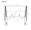
- a distance of the slant 38 to fall within such a range makes it possible to absorb rebound load parts Z that occur due to thickness of the first top cover forming flaps 7 and reaction of the first top cover forming flaps 7 when the first top cover forming flaps 7 are folded inwardly. This can prevent occurrence of curls 9a of the outer edge parts OE of the second top cover forming flaps 6 shown in Figure 25 .
- first top cover forming flaps 7 and the second top cover forming flaps 6 makes it possible to similarly absorb the rebound part Z in folding the second top cover forming flaps 6 after folding the first top cover forming flaps 7 and in folding the first top cover forming flaps 7 after folding the second top cover forming flaps 6. This can prevent occurrence of curls 9a of the outer edge parts OE.
- the packaging container 41 in folding up the packaging container 41, can be held by insertion of the insertion piece 6a and the insertion piece 4a on one side. Also, in folding up the packaging container 41, the packaging container 41 can be held only by insertion of either the insertion piece 6a or the insertion piece 4a.
- the first top cover forming flaps 7 and the first bottom plate forming flaps 5 each can be arbitrarily folded on the inward side or the outward side of the opposing side plate 3 connected thereto.
- a folding style is not limited to inward folding of the opposing side plates 3 and inward folding of the first top cover forming flaps 7 and the first bottom plate forming flaps 5.
- the packaging container of the present invention which is made of material such as cardboard, includes: a pair of first opposing side plates; a pair of second opposing side plates; bottom plate forming flaps which are connected to respective lower ends of the opposing side plates; and top cover forming flaps which are connected to respective upper ends of the opposing side plates, wherein the first opposing side plate, the bottom plate forming flap connected to the lower end of the first opposing side plate, and the top cover forming flap connected to the upper end of the first opposing side plate are provided with one continuous fold section thereacross centrally in the width direction of the first opposing side plate, and wherein the bottom plate forming flap connected to the lower end of at least one flap of the second opposing side plates and the top cover forming flap connected to the upper end of the at least one flap of the second opposing side plates are provided with respective fold parts substantially in parallel with connection lines to the at least one flap of the second opposing side plates, thereby using a leading end part ahead of the fold section as an insertion piece in folding up the packaging container.
- the packaging container of the present invention is arranged so that in the above-described packaging container, a tab provided on the top cover forming flap connected to the upper end of the second opposing side plate is inserted into a slit provided on the top cover forming flap connected to the upper end of the first opposing side plate, thereby forming a top cover.
- the packaging container of the present invention is arranged so that in the above-described packaging container, the top cover forming flaps connected to the respective upper ends of the second opposing side plates are first folded, and then, the top cover forming flaps connected to the respective upper ends of the first opposing side plates are folded, thereby forming a top cover.
- the packaging container of the present invention is arranged so that in the above-described packaging container, the bottom plate forming flap and the top cover forming flap which are connected respectively to the lower end and the upper end of the other of the second opposing side plates are folded so as to overlap the inner surface of the other of the second opposing side plates, the bottom plate forming flaps and the top cover forming flaps connected to the respective lower ends and upper ends of the first opposing side plates are folded so as to overlap the respective inner or outer surfaces of the first opposing side plates, and in a state where the first opposing side plate, and the bottom plate forming flap and the top cover forming flap connected to the first opposing side plate are inwardly folded in a form of the letter V along the fold section, the insertion pieces of leading end parts ahead of the respective fold sections provided on the bottom plate forming flap and the top cover forming flap connected respectively to the lower end and upper end of the one of the second opposing side plates are inserted inside the other of the second opposing side plates.
- flaps except for the bottom plate forming flap and the top cover forming flap which are connected respectively to the lower end and the upper end of the one of the second opposing side plates are overlapped the respective opposing side plates connected to the flaps.
- at least the bottom plate forming flap and the top cover forming flap which are connected respectively to the lower end and the upper end of the other of the second opposing side plates are folded so as to overlap the inner surface of the other of the second opposing side plates.
- the first opposing side plates, and the bottom plate forming flaps and the top cover forming flaps which are connected respectively to the first opposing side plates are folded inward in the form of the letter V along the respective fold lines, and the insertion pieces are inserted inside the other of the second opposing side plates, thereby holding the state of the packaging container compactly folded up for disposal.
- the packaging container includes:
- the second opposing side plate is equal to or smaller than the first opposing side plate in width, so that it is possible to fold up the packaging container into a decreased area, as compared with the case where the second opposing side plate is larger in width than the first opposing side plate.
- the packaging container of the present invention further includes a tongue, which extends from at least one of an upper end or a lower end of the second opposing side plate, for holding a folded state of the packaging container.
- a method for folding up a packaging container in which method the packaging container includes a pair of first opposing side plates and a pair of second opposing side plates, bottom plate forming flaps connected to respective lower ends of the first and second opposing side plates, and top cover forming flaps connected to respective upper ends of the first and second opposing side plates, wherein longitudinal fold sections each is provided across the first opposing side plate, the bottom plate forming flap connected to the lower end of the first opposing side plate, and the top cover forming flap connected to the upper end of the first opposing side plate, the longitudinal fold section being substantially orthogonal to respective connection lines between the first opposing side plate and the bottom plate forming flap and between the first opposing side plate and the top cover forming flap, and wherein a lateral fold section is provided on the top cover forming flap connected to an upper end of at least one of the second opposing side plates, the lateral fold section being substantially parallel to a connection line to the second opposing side plate, is characterized in that after the bottom plate forming flap and
- the tongue for holding a folded state extends from at least one of the upper end and the lower end of the second opposing side plate, so that it is possible to insert the tongue inside the other of the second opposing side plates in the folded packaging container. This maintains a folded state of the packaging container without opening out again by itself.
- the second top cover forming flap and the bottom plate forming flap is inserted inside the other of the second opposing side plates. This maintains a folded state of the packaging container without opening out again by itself.
- tongues, or the upper top forming flap and the bottom plate forming flap extends from both of the upper end and the lower end of the second opposing side plate.
- two tongues, or the upper top forming flap and the bottom plate forming flap are inserted inside the other of the second opposing side plate in the packaging container, which surely maintains a folded state of the packaging container without opening out again by itself.
- packaging container of the present invention which is the above-described packaging container, includes an explanation section, which is provided on at least one of the second opposing side plates, for explaining how to fold up the packaging container.
- the packaging container includes an explanation section, which is provided on at least one of the second opposing side plates, for explaining how to fold up the packaging container.
- the packaging container it is possible to fold up the packaging container while referring to the explanation section showing how to fold up the packaging container, facilitating folding operation of the packaging container.
- the explanation section is provided on at least one of the second opposing side plates, so that the explanation section without being disappeared can be referred to until folding operation of the packaging container is completed, ensuring the packaging container to be folded up.
- the packaging container of the present invention which is the above-described packaging container, includes a mark section for specifying a part to be folded, the mark section being provided in at least one of an end part of the first fold section on the first opposing side plate, an end part of the second fold section on the first bottom plate forming flap, and an end part of the third fold section on the first top cover forming flap.
- the packaging container includes a mark section for specifying a part to be folded, the mark section being provided on the longitudinal fold section provided across the first opposing side plate, the bottom plate forming flap connected to the lower end of the first opposing side plate, and the top cover forming flap connected to the upper end of the first opposing side plate.
- the mark section facilitates checking a position for folding.
- the mark section is provided in an end part of the first fold section on the first opposing side plate, an end part of the second fold section on the first bottom plate forming flap, or an end part of the third fold section on the first top cover forming flap. Because of this, the mark section appears at an easily viewable position.
- a length of the second top cover forming flap is substantially equal to a length of the first top cover forming flap, and at least one flap of the first and second top cover forming flaps has a gradually decreasing width with increase in length extending from the upper end of the second opposing side plate.
- the length of the second top cover forming flap is substantially equal to the length of the first top cover forming flap. This makes it possible to reduce paper excess parts caused by difference in length between the second top cover forming flap and the first top cover forming flap.
- this arrangement causes no breaks in the paper excess part during the course of distribution for the packaging container, allowing stability in quality of the packaging container.
- the flap is provided so as to have a gradually decreasing width with increase in length extending from the upper end of the opposing side plate. Because of this, when the first top cover forming flaps and the second top cover forming flaps are folded until they contact the respective inner surfaces of the two pairs of opposing side plates, the outer edge parts of the second top cover forming flaps can resist rebound of the first top cover forming flaps.
- a distance when leading end corner parts of the first and second top cover forming flaps are the closest to each other is set to fall within a range from 5mm to 20mm.
Landscapes
- Engineering & Computer Science (AREA)
- Mechanical Engineering (AREA)
- Cartons (AREA)
- Packaging Of Annular Or Rod-Shaped Articles, Wearing Apparel, Cassettes, Or The Like (AREA)
Description
- The present invention relates to a packaging container; according to the preamble of
claim 1, for storing an article and a method for folding up the packaging container. - Conventionally, a cardboard packaging container for storing a large size article to be packaged, especially when recycled or disposed as waste, is cut into small pieces, for example, by breaking with user's fingers to put them into a synthetic-resin disposal bag, or is forced to fold up into a decreased bulk to hold a folded state of the container with a sealing tape or a string.
- However, it requires a lot of muscle and much time to break the cardboard into small pieces with user's fingers. Further, when the cardboard packaging container is forced to fold up into a decreased bulk, it must be folded up at a part where there are no fold lines, also requiring a lot of muscle. Still further, it requires much time to wind the container with a sealing tape or a string while holding the folded state of the container, resulting in a burdensome folding operation.
- In order to solve such problems, a packaging container disclosed in
Japanese Unexamined Utility Model Application Publication No. 56226/1986 - Furthermore
JP 09-132230 A claim 1, made of paper which contains opposing side walls and flaps, while the side walls containing fold sections are smaller in width than other opposing side walls. - However, although the packaging container disclosed in the conventional publication is provided with a perforated cut line along a fold line on the flap, which enables flat folding by opening along the perforated cut line, it requires a lot of muscle to fold at a part where there are no fold lines on each plate as the above-described folding manner as well as requires much time to fold compactly at the midpoint of each plate as the above-described folding manner.
- An object of the present invention is to provide a packaging container and a method for folding up the packaging container which can be folded up easily and compactly for disposal as waste, recycling, and other purposes.
- The above object is achieved by the features disclosed in the characterizing portion of
claim 1. - According to the above invention, flaps except for the bottom plate forming flap and the top cover forming flap which are connected respectively to the lower end and the upper end of the one of the second opposing side are overlapped the respective opposing side plates connected to the flaps. At this moment, at least the bottom plate forming flap and the top cover forming flap which are connected respectively to the lower end and the upper end of the other of the second opposing side plates are folded so as to overlap the inner surface of the other of the second opposing side plates. In this state, the first opposing side plates, and the bottom plate forming flaps and the top cover forming flaps which are connected respectively to the first opposing side plates are folded inward in the form of the letter V along the respective fold lines, and the insertion pieces are inserted inside the other of the second opposing side plates.
- This makes it possible to provide a packaging container which can be folded up easily and compactly for disposal as waste, recycling, and other purposes.
- In order to achieve the above object it is of advantage that a packaging container of the present invention further comprises:
- first fold sections for folding therealong, each of the first fold sections being provided longitudinally in a substantially central part of the first opposing side plate;
- second fold sections for folding there along, each of the second fold sections being provided on the first bottom plate forming flap as an extension of the first fold section; and
- third fold sections for folding therealong, each of the third fold sections being provided on the first top cover forming flap as an extension of the first fold section.
- According to the above invention, in folding up the packaging container, it is possible to fold in the form of the letter V along the respective first fold sections of the first opposing side plates, the respective second fold sections of the first bottom plate forming flaps, and the respective third fold sections of the first top cover forming flaps.
- At this moment, in the present invention, the second opposing side plate is equal to or smaller than the first opposing side plate in width, so that it is possible to fold up the packaging container into a decreased area, as compared with the case where the second opposing side plate is larger in width than the first opposing side plate.
- Therefore, it is possible to provide a packaging container which can be folded up easily and compactly for disposal as waste, recycling, and other purposes.
- Yet further, in order to achieve the above object, a method for folding up a packaging container of the present invention includes:
- a pair of first opposing side plates and a pair of second opposing side plates;
- bottom plate forming flaps connected to respective lower ends of the first and second opposing side plates;
- top cover forming flaps connected to respective upper ends of the first and second opposing side plates; and
- longitudinal fold sections each being provided across the first opposing side plate, the bottom plate forming flap connected to the lower end of the first opposing side plate, and the top cover forming flap connected to the upper end of the first opposing side plate, the longitudinal fold section being substantially orthogonal to respective connection lines between the first opposing side plate and the bottom plate forming flap and between the first opposing side plate and the top cover forming flap; and
- a lateral fold section being provided on the top cover forming flap connected to an upper end of at least one of the second opposing side plates, the lateral fold section being substantially parallel to a connection line to the second opposing side plate,
- the method comprising the steps of:
- folding the bottom plate forming flap and the top cover forming flap respectively connected to a lower end and an upper end of the other of the second opposing side plates so as to overlap an inner surface of the other of the second opposing side plates;
- folding each of the bottom plate forming flaps and each of the top cover forming flaps respectively connected to the lower end and the upper end of the first opposing side plate so as to overlap an inner or outer surface of the first opposing side plate; and
- while maintaining a state where the first opposing side plate, and the bottom plate forming flap and the top cover forming flap connected to the first opposing side plate are inwardly folded in a form of the letter V along the longitudinal fold section, inserting the bottom plate forming flap connected to the lower end of the at least one of the second opposing side plates and an insertion piece of a leading end part ahead of the lateral fold section of the top cover forming flap connected to the upper end of the at least one of the second opposing side plates inside the other of the second opposing side plates.
- According to the above invention, the insertion piece for holding a folded state extends from at least one of the upper end and the lower end of the second opposing side plate, so that it is possible to insert the insertion piece inside the other of the second opposing side plates in the folded packaging container. This maintains a folded state of the packaging container without opening out again by itself.
- Therefore, it is possible to provide a packaging container and a method for folding up the packaging container which can be folded up easily and compactly for disposal as waste, recycling, and other purposes.
- For a fuller understanding of the nature and advantages of the invention, reference should be made to the ensuing detailed description taken in conjunction with the accompanying drawings.
-
-
Figure 1 is a developed view showing a packaging container of one embodiment of the present invention. -
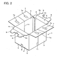
Figure 2 is a general perspective view showing a state of the packaging container before an article to be packaged is stored therein. -
Figure 3 is a perspective view showing a state of the packaging container when an article to be packaged is stored therein. -
Figure 4 is a cross-sectional view showing a state of the packaging container when an article to be packaged is stored therein. -
Figure 5 is a perspective view showing a state of the packaging container standing in a cylindrical manner to fold up the packaging container. -
Figure 6 is a perspective view showing a state of the packaging container in progress in folding up. -
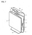
Figure 7 is a perspective view showing a state of the packaging container folded up so that its opposing side plates are in the form of the letter V. -
Figure 8 is a perspective view showing a state of the packaging container folded up by inserting insertion pieces. -
Figure 9 is a developed view showing a packaging container of another embodiment of the present invention. -
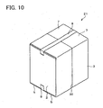
Figure 10 is a perspective view showing a state of the packaging container when an article to be packaged is stored therein. -
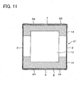
Figure 11 is a cross-sectional view showing a state of the packaging container when an article to be packaged is stored therein. -
Figure 12 is a perspective view showing a state of the packaging container after the article to be packaged is taken out of it. -
Figure 13 is a perspective view showing a state of the packaging container standing in a cylindrical manner. -
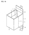
Figure 14 is a perspective view showing a state of the packaging container in progress in folding up. -
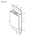
Figure 15 is a perspective view showing a state of the packaging container folded up so that its opposing side plates are in the form of the letter V. -
Figure 16 is a perspective view showing a state of the packaging container folded up by inserting insertion pieces. -
Figure 17 is a view showing a packaging container of still another embodiment of the present invention and a developed view showing a packaging container wherein an explanatory drawing showing how to fold up the packaging container is printed onto one side plate. -
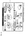
Figure 18 is a front view showing an explanatory drawing for explaining how to fold up the packaging container. -
Figure 19 is a perspective view showing a state of the folded packaging container with the explanatory drawing. -
Figure 20 is a perspective view showing another state of the folded packaging container with the explanatory drawing. -
Figure 21 a perspective view explaining how to hold up the packaging container with a fold position mark. -
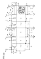
Figure 22 is a developed view showing the packaging container wherein the respective lengths of first top cover forming flaps are substantially the same as those of second top cover forming flaps, and the first and second top cover forming flaps are provided respective slants so that widths of the first and second top cover forming flaps decrease with increase in lengths of the first and second top cover forming flaps. -
Figure 23 is a developed view showing a packaging container wherein the respective lengths of first top cover forming flaps are different from those of second top cover forming flaps. -
Figure 24 is a plan view showing a delivered form of the packaging container shown inFigure 22 . -
Figure 25 is a perspective view showing a problem occurring during a step of folding a top cover forming flap without slants. -
Figure 26 is a perspective view showing a step of folding first top cover forming flaps with slants and a second top cover forming flap in the packaging container shown inFigure 22 . -
Figure 27 is a cross-sectional view taken along line A-A of the packaging container shown inFigure 26 . -
Figure 28(a) is a perspective view showing a problem caused in the case where the respective slants of bottom plate forming flaps are large, andFigure 28(b) is a perspective view showing the packaging container improving the problem shown inFigure 28(a) by other method without providing slants. -
Figure 29(a) is an enlarged view of a relevant part of a top cover forming flap, andFigure 29(b) is a perspective view showing a state where the top cover forming flap is folded inward. - The following will describe one embodiment of the present invention with reference to
Figures 1 through 8 . - A
packaging container 1 of the present embodiment, as shown inFigure 1 , includes a pair of second opposingside plates 2, a pair of first opposingside plates 3, second bottomplate forming flaps 4 connected respectively to the lower ends of the second opposingside plates 2, first bottomplate forming flaps 5 connected respectively to the lower ends of the first opposingside plates 3, second topcover forming flaps 6 connected respectively to the upper ends of the second opposingside plates 2, and first topcover forming flaps 7 connected respectively to the upper ends of the first opposingside plates 3. Note that, a shape of thepackaging container 1 is, but not limited to, rectangle or square. Moreover, thepackaging container 1 according to the present embodiment is made of cardboard. However, the material of thepackaging container 1 is not limited to cardboard, and any material may be adopted so long as it is foldable material, such as paper and plastic. - The pair of second opposing
side plates 2 and the pair of first opposingside plates 3 are alternately connected to one another, forming a situation where four side plates are continuously connected to one another to surround a packaging space on all four sides. The secondopposing side plates 2 are set to be equal to or smaller than the first opposingside plates 3 in width. The first bottomplate forming flaps 5 are provided respectively to the lower ends 3a of the first opposingside plates 3, and the second bottomplate forming flaps 4 are provided respectively to the lower ends 2a of the second opposingside plates 2. - The second bottom
plate forming flaps 4 and the first bottomplate forming flaps 5 form overlap structure of a bottom plate in thepackaging container 1. Specifically, after the second bottomplate forming flaps 4 are folded, the first bottomplate forming flaps 5 are folded, thereby forming the bottom plate. In this regard, abutting parts of the first bottomplate forming flaps 5, as shown inFigure 2 , are sealed with a sealingtape 8. Note that, material of the sealingtape 8 is not especially limited so long as it is material that can hold the abutting parts, such as packing tape and paper tape. - Meanwhile, the first top
cover forming flaps 7 are connected respectively to the upper ends 3b of the first opposingside plates 3, and the second topcover forming flaps 6 are connected respectively to the upper ends 2b of the second opposingside plates 2. As shown inFigure 3 , the second topcover forming flaps 6 and the first topcover forming flaps 7 form overlap structure of a top cover in thepackaging container 1. Specifically, after the first topcover forming flaps 7 are folded with their edges abutting, the second topcover forming flaps 6 are folded and, tabs 9 (seeFigure 1 ) provided on each of the second topcover forming flaps 6 are inserted respectively intoslits 7a provided on each of the first topcover forming flaps 7, thereby forming the top cover. - More specifically, the second top
cover forming flaps 6 are folded so as to be astride the two first topcover forming flaps 7, and thetabs 9 are inserted into therespective slits 7a provided on the two first topcover forming flaps 7, thereby maintaining a closed state of the top cover. This arrangement makes it possible to maintain a closed state of the top cover simply without using a tape such as the sealingtape 8. - Each of the second top
cover forming flaps 6 is provided with afold section 10 along which the topcover forming flap 6 itself can be fold, substantially in parallel with a connection line of theupper end 2b of the second opposingside plate 2. This facilitates the insertion of thetabs 9 into therespective slits 7a. Specifically, folding the second topcover forming flaps 6 along therespective fold sections 10 facilitates the insertion of thetabs 9 into therespective slits 7a. - Further, the
fold sections 10 are used to forminsertion pieces 6a in folding up thepackaging container 1. Note that, thefold section 10 is preferably formed as typical ruled line. However, it may be formed in a perforated or serrated manner, and any type of form may be adopted as long as it is foldable therealong. - Meanwhile, the first opposing
side plates 3, as shown inFigure 1 , are provided with respectivefirst fold sections 11a in a substantially central position across the width direction of the first opposingside plates 3. Thefirst fold sections 11a are substantially parallel to the longitudinal direction of the first opposingside plates 3, and the first opposingside plates 3 themselves can be folded along thefirst fold sections 11a. Further, the first bottomplate forming flaps 5 are provided with respectivesecond fold sections 11b in a substantially central part across the width direction of the first bottom plate forming flaps 5. Thesecond fold sections 11b are provided respectively in a form of continuing into thefirst fold sections 11a, i.e. as an extension of thefirst fold sections 11a, and the first bottomplate forming flaps 5 themselves can be folded along thesecond fold sections 11b. - Moreover, the first top
cover forming flaps 7 are provided with respectivethird fold sections 11c in a substantially central part across the width direction of the first top cover forming flaps 7. The first topcover forming flaps 7 are provided respectively in a form of continuing into thefirst fold sections 11a, and the first topcover forming flaps 7 themselves can be folded along thethird fold sections 11c. - The three fold sections: the
first fold section 11a, thesecond fold section 11b, and thethird fold section 11c, which are provided continuously, constitute onecontinuous fold section 11. A preferable form of thefold section 11 is, for example, a line with a fold made in advance, a line with recessed parts, and a line with a series of small cuts halfway the thickness direction of thefold sections - Meanwhile, the second bottom
plate forming flaps 4, as shown inFigure 1 , are provided withrespective fold sections 12 each of which is substantially parallel to thelower end 2a of the second opposingside plate 2. The leading end parts ahead of thefold sections 12 of the second bottomplate forming flaps 4 are cut tapered on their opposite sides and adapted to be used asinsertion pieces 4a. Theinsertion pieces 4a are used in folding thepackaging container 1. Note that, thefold section 12 can be provided on at least one of the second bottom plate forming flaps 4. Further, although thefold section 12 is preferably formed as typical ruled line, it may be formed in a perforated or serrated manner. - The following will describe a process for folding up the
packaging container 1 in the above arrangement. - As shown in
Figure 4 , a packagedarticle 13 protected by cushioningmaterial 14, for example, is stored inside the assembledpackaging container 1. Note that, it is preferable that the cushioningmaterial 14 is made of foaming polystyrol, and it may be made of cardboard and the like. However, any material may be used for thecushioning material 14. - The packaged
article 13 and thecushioning material 14 are taken out of thepackaging container 1 while the second topcover forming flaps 6 and the first topcover forming flaps 7 are kept opened. Next, the sealingtape 8 is peeled away and, as shown inFigure 5 , the first and second bottomplate forming flaps cover forming flaps side plates packaging container 1 in a cylindrical manner. - With this state, it is preferable that while the second bottom
plate forming flap 4 and the second topcover forming flap 6 which are respectively connected to thelower end 2a and theupper end 2b of one of the second opposingside plates 2 are left unfold, all of the other flaps, i.e. the other of the second bottomplate forming flaps 4, the first bottomplate forming flaps 5, the other of the second topcover forming flaps 6, and the first topcover forming flaps 7, are folded so as to overlap the other of the second opposingside plates 2 and the first opposingside plates 3, respectively, connected thereto. - More specifically, the second bottom
plate forming flap 4 and the second topcover forming flap 6 which are respectively connected to thelower end 2a and theupper end 2b of one of the second opposingside plates 2 are folded inward so as to overlap the inner surface of the other of the second opposingside plates 2. Further, as shown inFigure 6 , the first bottomplate forming flaps 5 and the first topcover forming flaps 7 each of which are respectively connected to thelower end 3a and theupper end 3b of the first opposingside plate 3 are folded outward so as to overlap the outer surface of the first opposingside plate 3. Note that, the first bottomplate forming flaps 5 and the first topcover forming flaps 7 each may be folded inward so as to overlap the inner surfaces of the first opposingside plates 3, respectively. - In such a state, as shown in
Figure 7 , the first opposingside plates 3, the first bottomplate forming flaps 5, and the first topcover forming flaps 7 are inwardly folded in the form of the letter V at thefold sections 11 inside thepackaging container 1 so as to be sandwiched between the second opposingside plates 2. - Next, the
insertion piece 4a is formed by folding along thefold section 12 that is provided on the second bottomplate forming flap 4, and theinsertion piece 6a is formed by folding along thefold sections 10 that is provided on the second topcover forming flap 6. Theinsertion pieces Figure 8 , are inserted inside the other of the second opposingside plates 2. More specifically, theinsertion pieces plate forming flaps 4 and the other of the second topcover forming flaps 6 that have been folded so as to overlap the inner surface of the other of the opposingside plate 2. - This brings the
packaging container 1 in a compactly folded state. Since theinsertion pieces side plates 2 are inserted inside the other of the second opposingside plates 2, thepackaging container 1 that has been folded does not open out again by itself and maintains its folded state. The thus foldedpackaging container 1 with its compact form maintained is suitable for being recycled or disposed as waste, for example. - Note that, although the
packaging container 1 has been held with both of theinsertion pieces packaging container 1 is not limited to this. For simplification of a folding process, thepackaging container 1 can be held only with one of theinsertion pieces insertion piece 4a. - In this case, the top
cover forming flap 6 that is not used for insertion can be folded inward as all other flaps, i.e. the second bottomplate forming flap 4, the first bottomplate forming flaps 5, the second topcover forming flap 6, and the first topcover forming flaps 7, so as to overlap the second opposingside plates 2 and the first opposingside plates 3 connected thereto. Conversely, no problem would occur when thepackaging container 1 is held only by using theinsertion piece 6a. That is, thepackaging container 1 can be held when an insertion piece that is provided to at least one flap selected arbitrarily from among the second topcover forming flaps 6 and the second bottomplate forming flaps 4 is inserted inside thepackaging container 1. - The following will describe another embodiment of the present invention with reference to
Figures 9 through 16 . Note that, the configuration except for the description in the present embodiment is the same as that described in the First Embodiment. For the purpose of explanation, members having the same functions as those described in the drawings of the First Embodiment are given the same reference numerals and detailed explanations thereof are omitted here. - A
packaging container 21 of the present embodiment, as shown inFigure 9 , is different from thepackaging container 1 of the First Embodiment in that second topcover forming flaps 26 and second bottomplate forming flaps 24 each of which is respectively connected to a second opposingside plate 2 have a rectangular shape, only the second topcover forming flap 26 and the second bottomplate forming flap 24 which are provided to one of the second opposingside plates 2 are provided withfold sections - Specifically, in the
packaging container 21 of the present embodiment, as shown inFigure 9 , one of the second bottomplate forming flaps 24 connected to the respective lower ends 2a of the second opposingside plates 2 having shorter sides and the second topcover forming flap 26 connected to theupper end 2b of the second opposingside plate 2 that is connected to the one of the bottomplate forming flaps 24 are provided withfold sections lower end 2a and theupper end 2b that are connection lines to the second opposingside plate 2. Also, leading end parts ahead of thefold sections insertion pieces packaging container 1 is disposed as waste and recycled. Note that, thefold sections - The following will describe a process for folding up the
packaging container 21 in the above arrangement. - As shown in
Figure 10 , a packagedarticle 13 protected by cushioningmaterial 14, for example, is stored inside the assembledpackaging container 21. - As shown in
Figure 12 , the packagedarticle 13 and thecushioning material 14 are taken out of thepackaging container 21 while the second topcover forming flaps 26 and first topcover forming flaps 7 are kept opened. Next, a sealingtape 8 is peeled away and, as shown inFigure 13 , the second bottomplate forming flaps 24, the first bottomplate forming flaps 5, and the topcover forming flaps 26, and the first topcover forming flaps 7 are opened to become flush with respect to the two pairs of opposingside plates packaging container 21 in a cylindrical manner. - With this state, as shown in
Figure 14 , while the second bottomplate forming flap 24 and the second topcover forming flap 26 which are respectively connected to thelower end 2a and theupper end 2b of one of the second opposingside plates 2 are left unfold, all of the other flaps, i.e. the other of the second bottomplate forming flaps 24, the first bottomplate forming flaps 5, the other of the second topcover forming flaps 26, and the first topcover forming flaps 7, are folded, for example, inwardly so as to overlap the other of the second opposingside plates 2 and the first opposingside plates 3, respectively, connected thereto. - In such a state, as shown in
Figure 15 , the opposingside plates 3, the first bottomplate forming flaps 5, and the first topcover forming flaps 7 are inwardly folded in the form of the letter V at thefold sections 11 inside thepackaging container 21 so as to be sandwiched between the second opposingside plates 2. - Next, the
insertion piece 24a is formed by folding along thefold section 32 that is provided on the one of the second bottomplate forming flaps 24, and theinsertion piece 26a is formed by folding along thefold section 30 that is provided on the one of the second top cover forming flaps 26. Theinsertion pieces Figure 8 , are inserted inside the other of the second opposingside plates 2. More specifically, theinsertion pieces plate forming flaps 24 and the other of the second topcover forming flaps 26 that have been folded so as to overlap the inner surface of the other of the opposingside plates 2. - This brings the
packaging container 21 in a compactly folded state. Since theinsertion pieces side plates 2 are inserted inside the other of the second opposingside plates 2, thepackaging container 21 that has been folded does not open out again by itself and maintains its folded state. The thus foldedpackaging container 21 with its compact form maintained is suitable for being recycled or disposed as waste, for example. - Note that, for simplification of a folding process, it is also possible to hold the
packaging container 1 only with one of theinsertion pieces - Thus, although the
fold section 12 is also provided on the other of the second bottomplate forming flaps 4 in thepackaging container 1 of the First Embodiment, thefold section 12 does not specially need to be provided on the other of the second bottom plate forming flaps as described in the present embodiment. However, it is not necessarily limited to this arrangement. Thefold sections plate forming flaps 24 and the other of the second topcover forming flaps 26, in the same manner as the one of the second bottomplate forming flaps 24 and the one of the second top cover forming flaps 26. - Further, the first opposing
side plate 3 having longer sides, the first bottomplate forming flap 5 connected to thelower end 3a of the first opposingside plate 3, and the first topcover forming flap 7 connected to theupper end 3b of the first opposingside plate 3 are provided with onecontinuous fold section 11 thereacross centrally in the width direction of the first opposingside plate 3. However, it is not necessarily limited to this arrangement. For example, the second opposingside plate 2 having shorter sides, the second bottomplate forming flap lower end 2a of the second opposingside plate 2, and the second topcover forming flap upper end 2b of the opposingside plate 2 may be provided with one continuous fold section thereacross centrally in the width direction of the second opposingside plate 2. That is, an opposing side plate where thefold section 11 is provided is not limited to the opposing side plate having shorter sides. In addition, it is sufficient that thefold section 11 is provided in a substantially central part in the width direction of the opposing side plate. - The following will describe still another embodiment of the present invention with reference to
Figures 17 though 29. Note that, the configuration except for the description in the present embodiment is the same as those described in the First Embodiment and the second Embodiment. For the purpose of explanation, members having the same functions as those described in the drawings of the First Embodiment and the Second Embodiment are given the same reference numerals and detailed explanations thereof are omitted here. - A
packaging container 41 of the present embodiment, as shown inFigure 17 , is totally different from thepackaging container 1 of the First Embodiment in that the second opposingside plate 2 is provided with anexplanatory drawing 36 as an explanation section for explaining how to fold up thispackaging container 41, as shown inFigure 18 . - In the
packaging container 41 of the present embodiment, it is possible to carry out a folding operation while referring to theexplanatory drawing 36 until folding of thepackaging container 41 is completed, ensuring thepackaging container 41 to be folded up. Note that, it is preferable that theexplanatory drawing 36 is provided on both of the second opposingside plates 2 because theexplanatory drawings 36 could be referred to from any directions in folding up thepackaging container 41. However, the explanatory drawing 36 can be provided on at least one of the second opposingside plates 2. Moreover, the most preferable method for providing theexplanatory drawing 36, but is not especially limited, is printing because printing is a simple and easy method and allows cost reduction. - In the present embodiment, the
explanatory drawing 36 is provided on the second opposingside plate 2. Therefore, inoperating Steps 1 through 4 amongSteps 1 though 6 for a folding procedure shown inFigure 18 , even after the first opposingside plates 3 are folded inward along therespective fold sections 11, which are provided substantially in the central part of the first opposingside plates 3, according to theStep 4, as shown inFigures 19 and20 , the explanatory drawing 36 without being disappeared can be referred to until operation of thestep 6 is completed. - Further, in the
packaging container 41 of the present embodiment, as shown inFigure 17 , the first bottomplate forming flaps 5 are respectively provided with fold position marks 35 as a mark section for use in explanation of how to fold up thepackaging container 41, in the vicinity of leaders of thesecond fold sections 11b, i.e. in the vicinity of the lower ends 3a of the first bottom plate forming flaps 5. Providing the fold position marks 35 facilitates checking of the positions indicating thefold sections 11. - Note that, the fold position marks 35 may be provided respectively in the vicinity of leaders of
third fold sections 11c provided on first topcover forming flaps 7 or may be provided respectively in the vicinity of leaders offirst fold sections 11a provided on the first opposingside plates 3. In addition, the fold position marks 35 may be provided in the vicinity of all leaders of thefirst fold sections 11a, thesecond fold sections 11b, and thethird fold sections 11c. That is, the fold position marks 35 may be provided in the vicinity of leaders of at least one of thefirst fold sections 11a, thesecond fold sections 11b, and thethird fold sections 11c. - Further, shape, color, and provision means of the
fold position mark 35 are not especially limited, so long as it can facilitate checking a position for folding up thepackaging container 41. For example, thefold position mark 35 is a circle filled in with black, as shown inFigure 21 , However, shape of thefold position mark 35 is not limited to this, and it may be a shape such as triangle, square, rhombus, or star shape. In addition, color for filling in thefold position mark 35 is not limited to black. It may be any color, and it does not matter whether thefold position mark 35 is filled in or not. In providing thefold position mark 35, printing is, but not limited to, the most preferable method because printing is a simple and easy method and allows cost reduction. For example, thefold position mark 35 can be provided with a perforated shape. - Further, in the
packaging container 41 of the present embodiment, as shown inFigure 22 , the respective lengths X of the first topcover forming flaps 7 each of which extends from the end part of the first opposingside plate 3 are substantially the same as the respective lengths Y of the second topcover forming flaps 6 each of which extends from the end part of the second opposingside plate 2. This arrangement enables reduction of a paper excess part α which is difference between the length X of the first topcover forming flap 7 and the length Y of the second topcover forming flap 6, caused in a box form as shown inFigure 23 . Note that, in the present embodiment, the length of the twoinsertion pieces 6a is also substantially the same as the length Y of the second topcover forming flap 6. - Moreover, as shown in
Figure 24 , the length X is substantially the same as the length Y. Unlike the arrangement inFigure 23 , this arrangement causes no breaks in the paper excess part α of the top cover forming flap, which is a projected extension piece, during the course of distribution for thepackaging container 41. This allows stability in quality of thepackaging container 41. - Further, in the present embodiment, the first top
cover forming flap 7 and the second topcover forming flap 6 are provided withslants cover forming flap 7 and the second topcover forming flap 6 decrease with increase in the lengths X and Y. - In the case where the
slants cover forming flap 7 and the second the topcover forming flap 6, the following problem would be caused in folding the first topcover forming flaps 7 and the second topcover forming flaps 6 as shown inFigure 25 . - That is, in the case where the first top
cover forming flap 7 and the second topcover forming flap 6 without providing therespective slants side plate 2 and the opposingside plate 3, curls 9a occur in the outer edge parts OE of the second topcover forming flap 6 due to loads caused by thickness of the first topcover forming flap 7 and reaction of the first topcover forming flap 7 when the first topcover forming flap 7 are folded inwardly. This causes a tendency that the second topcover forming flaps 6 move away in the outward direction indicated by an arrow (a thick arrow inFigure 25 ), which could make it difficult to carry out inwardly folding operation of the second top cover forming flaps 6. - In order to solve the problem, as shown in
Figure 22 , the first topcover forming flap 7 and the second topcover forming flap 6 are provided with theslants cover forming flaps 7 and the second topcover forming flaps 6 are folded inward until they contact the respective inner surfaces of the opposingside plates 2 and the opposingside plates 3, the outer edge parts OE of the second topcover forming flaps 6 resist rebound of the first top cover forming flaps 7. This facilitates folding of these flaps. - That is, by providing the
slants 38 to the second topcover forming flap 6, the outer edge parts OE of the second topcover forming flaps 6 can resist the first topcover forming flaps 7 regardless of a folding order. This results in facilitating inwardly folding and holding thepackaging container 41. - Incidentally, as the first top
cover forming flaps 7 and the second topcover forming flaps 6, the first bottomplate forming flaps 5 and the second bottomplate forming flaps 4 can be respectively provided with theslants plate forming flaps 5, the problem of a large misalignment as indicated by an arrow C occurs in forming a bottom plate, as shown inFigure 28(a) . - In order to solve this problem, a manner that the
slants 37 are not set on the first bottomplate forming flaps 5 can be used. That is, as shown inFigure 29(a) , cut parts K are provided ahead of thefold section 12 located between the second bottomplate forming flap 4 and theinsertion piece 4a so as to make two functional parts, a flap KI part and a flap 4I part, on both sides of thefold section 12. With this arrangement, in forming a bottom plate as shown inFigure 29(b) , the second bottomplate forming flaps 4 with slants are first folded inward. Then, in folding the first bottomplate forming flaps 5 without slants, as indicated by an arrow D, the flap 4I part of the second bottomplate forming flap 4 is held down by a substantially half part of the first bottomplate forming flap 5. Further, as indicated by an arrow E, theinsertion piece 4a is pulled up to keep tight the flap KI part, thereby holding the first bottom plate forming flaps 5. With this manner, it is possible to inwardly fold the second bottomplate forming flaps 4 and the first bottomplate forming flaps 5 without provision of theslants 37 to the first bottom plate forming flaps 5. - When the first bottom
plate forming flaps 5 each having such a shape are folded to form a bottom plate, it is possible to prevent misalignment indicated by the arrow C inFigure 28(a) , as shown inFigure 28(b) . - Note that, the
slants slants - Here, when the second top
cover forming flaps 6 and the first topcover forming flaps 7 are folded inward until they contact the respective inner surfaces of the second opposingside plates 2 and the first opposingside plates 3, it is preferable that a distance of theslant 38 between a leading end corner part of the topcover forming flap 7 and a leading end corner part of the topcover forming flap 6 which is the closest to the leading end corner part of the topcover forming flap 7 is set to fall within a range from 5mm to 20mm, as shown inFigure 26 . Setting a distance of theslant 38 to fall within such a range makes it possible to absorb rebound load parts Z that occur due to thickness of the first topcover forming flaps 7 and reaction of the first topcover forming flaps 7 when the first topcover forming flaps 7 are folded inwardly. This can prevent occurrence ofcurls 9a of the outer edge parts OE of the second topcover forming flaps 6 shown inFigure 25 . - Further, providing the
respective slants cover forming flaps 7 and the second topcover forming flaps 6 makes it possible to similarly absorb the rebound part Z in folding the second topcover forming flaps 6 after folding the first topcover forming flaps 7 and in folding the first topcover forming flaps 7 after folding the second top cover forming flaps 6. This can prevent occurrence ofcurls 9a of the outer edge parts OE. - The present invention is not limited to the aforementioned embodiments and modified examples and susceptible of various changes within the scope of the accompanying claims. An embodiment obtained by suitable combinations of technical means disclosed in the different embodiments and modified examples also fall within the technical scope of the present invention.
- For example, in folding up the
packaging container 41, thepackaging container 41 can be held by insertion of theinsertion piece 6a and theinsertion piece 4a on one side. Also, in folding up thepackaging container 41, thepackaging container 41 can be held only by insertion of either theinsertion piece 6a or theinsertion piece 4a. - Further, for example, in folding the first top
cover forming flaps 7 and the first bottomplate forming flaps 5, the first topcover forming flaps 7 and the first bottomplate forming flaps 5 each can be arbitrarily folded on the inward side or the outward side of the opposingside plate 3 connected thereto. A folding style is not limited to inward folding of the opposingside plates 3 and inward folding of the first topcover forming flaps 7 and the first bottom plate forming flaps 5. - Thus, the packaging container of the present invention, which is made of material such as cardboard, includes: a pair of first opposing side plates; a pair of second opposing side plates; bottom plate forming flaps which are connected to respective lower ends of the opposing side plates; and top cover forming flaps which are connected to respective upper ends of the opposing side plates, wherein the first opposing side plate, the bottom plate forming flap connected to the lower end of the first opposing side plate, and the top cover forming flap connected to the upper end of the first opposing side plate are provided with one continuous fold section thereacross centrally in the width direction of the first opposing side plate, and wherein the bottom plate forming flap connected to the lower end of at least one flap of the second opposing side plates and the top cover forming flap connected to the upper end of the at least one flap of the second opposing side plates are provided with respective fold parts substantially in parallel with connection lines to the at least one flap of the second opposing side plates, thereby using a leading end part ahead of the fold section as an insertion piece in folding up the packaging container.
- Further, the packaging container of the present invention is arranged so that in the above-described packaging container, a tab provided on the top cover forming flap connected to the upper end of the second opposing side plate is inserted into a slit provided on the top cover forming flap connected to the upper end of the first opposing side plate, thereby forming a top cover.
- Further, the packaging container of the present invention is arranged so that in the above-described packaging container, the top cover forming flaps connected to the respective upper ends of the second opposing side plates are first folded, and then, the top cover forming flaps connected to the respective upper ends of the first opposing side plates are folded, thereby forming a top cover.
- Still further, the packaging container of the present invention is arranged so that in the above-described packaging container, the bottom plate forming flap and the top cover forming flap which are connected respectively to the lower end and the upper end of the other of the second opposing side plates are folded so as to overlap the inner surface of the other of the second opposing side plates, the bottom plate forming flaps and the top cover forming flaps connected to the respective lower ends and upper ends of the first opposing side plates are folded so as to overlap the respective inner or outer surfaces of the first opposing side plates, and in a state where the first opposing side plate, and the bottom plate forming flap and the top cover forming flap connected to the first opposing side plate are inwardly folded in a form of the letter V along the fold section, the insertion pieces of leading end parts ahead of the respective fold sections provided on the bottom plate forming flap and the top cover forming flap connected respectively to the lower end and upper end of the one of the second opposing side plates are inserted inside the other of the second opposing side plates.
- With this arrangement, flaps except for the bottom plate forming flap and the top cover forming flap which are connected respectively to the lower end and the upper end of the one of the second opposing side plates are overlapped the respective opposing side plates connected to the flaps. At this moment, at least the bottom plate forming flap and the top cover forming flap which are connected respectively to the lower end and the upper end of the other of the second opposing side plates are folded so as to overlap the inner surface of the other of the second opposing side plates. In this state, the first opposing side plates, and the bottom plate forming flaps and the top cover forming flaps which are connected respectively to the first opposing side plates are folded inward in the form of the letter V along the respective fold lines, and the insertion pieces are inserted inside the other of the second opposing side plates, thereby holding the state of the packaging container compactly folded up for disposal.
- In order to solve the above problem, in a packaging container including a pair of first opposing side plates and a pair of second opposing side plates surrounding a package space, in which first bottom plate forming flaps for forming a bottom plate are connected to respective lower ends of the first opposing side plates, and first top cover forming flaps for forming a bottom plate are connected to respective upper ends of the first opposing side plates,
the packaging container includes: - first fold sections for folding therealong, each of the first fold sections being provided longitudinally in a substantially central part of the first opposing side plate;
- second fold sections for folding therealong, each of the second fold sections being provided on the first bottom plate forming flap as an extension of the first fold section; and
- third fold sections for folding therealong, each of the third fold sections being provided on the first top cover forming flap as an extension of the first fold section,
- the second opposing side plate being equal to or smaller than the first opposing side plate in width.
- According to the above invention, in folding up the packaging container, it is possible to fold in the form of the letter V along the respective first fold sections of the first opposing side plates, the respective second fold sections of the first bottom plate forming flaps, and the respective third fold sections of the first top cover forming flaps.
- At this moment, in the present invention, the second opposing side plate is equal to or smaller than the first opposing side plate in width, so that it is possible to fold up the packaging container into a decreased area, as compared with the case where the second opposing side plate is larger in width than the first opposing side plate.
- Therefore, it is possible to provide a packaging container which can be folded up easily and compactly for disposal as waste, recycling, and other purposes.
- Further, the packaging container of the present invention further includes a tongue, which extends from at least one of an upper end or a lower end of the second opposing side plate, for holding a folded state of the packaging container.
- In order to solve the above problem, a method for folding up a packaging container in which method the packaging container includes a pair of first opposing side plates and a pair of second opposing side plates, bottom plate forming flaps connected to respective lower ends of the first and second opposing side plates, and top cover forming flaps connected to respective upper ends of the first and second opposing side plates,
wherein longitudinal fold sections each is provided across the first opposing side plate, the bottom plate forming flap connected to the lower end of the first opposing side plate, and the top cover forming flap connected to the upper end of the first opposing side plate, the longitudinal fold section being substantially orthogonal to respective connection lines between the first opposing side plate and the bottom plate forming flap and between the first opposing side plate and the top cover forming flap, and
wherein a lateral fold section is provided on the top cover forming flap connected to an upper end of at least one of the second opposing side plates, the lateral fold section being substantially parallel to a connection line to the second opposing side plate,
is characterized in that after the bottom plate forming flap and the top cover forming flap respectively connected to a lower end and an upper end of the other of the second opposing side plates are folded so as to overlap an inner surface of the other of the second opposing side plates,
each of the bottom plate forming flaps and each of the top cover forming flaps respectively connected to the lower end and the upper end of the first opposing side plate are folded so as to overlap an inner or outer surface of the first opposing side plate, and thereafter,
while maintaining a state where the first opposing side plate, and the bottom plate forming flap and the top cover forming flap connected to the first opposing side plate are inwardly folded in a form of the letter V along the longitudinal fold section,
the bottom plate forming flap connected to the lower end of the at least one of the second opposing side plates and an insertion piece of a leading end part ahead of the lateral fold section of the top cover forming flap connected to the upper end of the at least one of the second opposing side plates are inserted inside the other of the second opposing side plates. - According to the above invention, the tongue for holding a folded state extends from at least one of the upper end and the lower end of the second opposing side plate, so that it is possible to insert the tongue inside the other of the second opposing side plates in the folded packaging container. This maintains a folded state of the packaging container without opening out again by itself.
- Similarly, at least one of the second top cover forming flap and the bottom plate forming flap is inserted inside the other of the second opposing side plates. This maintains a folded state of the packaging container without opening out again by itself.
- Therefore, it is possible to provide a packaging container and a method for folding up the packaging container which can be folded up easily and compactly for disposal as waste, recycling, and other purposes.
- Note that, in the present invention, it is preferable that tongues, or the upper top forming flap and the bottom plate forming flap extends from both of the upper end and the lower end of the second opposing side plate. With this arrangement, two tongues, or the upper top forming flap and the bottom plate forming flap are inserted inside the other of the second opposing side plate in the packaging container, which surely maintains a folded state of the packaging container without opening out again by itself.
- Further, in the packaging container of the present invention, which is the above-described packaging container, includes an explanation section, which is provided on at least one of the second opposing side plates, for explaining how to fold up the packaging container.
- Still further, in the method for folding up the packaging container of the present invention, which is the above-described method for folding up the packaging container, the packaging container includes an explanation section, which is provided on at least one of the second opposing side plates, for explaining how to fold up the packaging container.
- According to the above invention, it is possible to fold up the packaging container while referring to the explanation section showing how to fold up the packaging container, facilitating folding operation of the packaging container. In addition, the explanation section is provided on at least one of the second opposing side plates, so that the explanation section without being disappeared can be referred to until folding operation of the packaging container is completed, ensuring the packaging container to be folded up.
- Yet further, the packaging container of the present invention, which is the above-described packaging container, includes a mark section for specifying a part to be folded, the mark section being provided in at least one of an end part of the first fold section on the first opposing side plate, an end part of the second fold section on the first bottom plate forming flap, and an end part of the third fold section on the first top cover forming flap.
- Further, in the method for folding up the packaging container of the present invention, which is the above-described method for folding up the packaging container, the packaging container includes a mark section for specifying a part to be folded, the mark section being provided on the longitudinal fold section provided across the first opposing side plate, the bottom plate forming flap connected to the lower end of the first opposing side plate, and the top cover forming flap connected to the upper end of the first opposing side plate.
- According to the above invention, referring to the mark section facilitates checking a position for folding. In addition, the mark section is provided in an end part of the first fold section on the first opposing side plate, an end part of the second fold section on the first bottom plate forming flap, or an end part of the third fold section on the first top cover forming flap. Because of this, the mark section appears at an easily viewable position.
- Still further, in the packaging container of the present invention, which is the above-described packaging container, a length of the second top cover forming flap is substantially equal to a length of the first top cover forming flap, and at least one flap of the first and second top cover forming flaps has a gradually decreasing width with increase in length extending from the upper end of the second opposing side plate.
- According to the above invention, the length of the second top cover forming flap is substantially equal to the length of the first top cover forming flap. This makes it possible to reduce paper excess parts caused by difference in length between the second top cover forming flap and the first top cover forming flap.
- In addition, this arrangement causes no breaks in the paper excess part during the course of distribution for the packaging container, allowing stability in quality of the packaging container.
- Moreover, the flap is provided so as to have a gradually decreasing width with increase in length extending from the upper end of the opposing side plate. Because of this, when the first top cover forming flaps and the second top cover forming flaps are folded until they contact the respective inner surfaces of the two pairs of opposing side plates, the outer edge parts of the second top cover forming flaps can resist rebound of the first top cover forming flaps.
- This can facilitate inwardly folding these top cover forming flaps regardless of a folding order. In addition, since the rebound can be resisted, it is possible to surely hold the folded state of the packaging container in folding up the packaging container.
- Still further, in the packaging container of the present invention, which is the above-described packaging container, when the first and second top cover forming flaps are folded until contacting respective inner surfaces of the first and second opposing side plates, a distance when leading end corner parts of the first and second top cover forming flaps are the closest to each other is set to fall within a range from 5mm to 20mm.
- According to the above invention, it is surely possible to absorb rebound load parts that occur due to thickness of the top cover forming flaps and reaction of the top cover forming flaps when the top cover forming flaps are folded inwardly. This can prevent occurrence of curls of the outer edge parts of the top cover forming flaps.
- The invention being thus described, it will be obvious that the same may be varied in many ways, falling within the scope of the following claims.
Claims (13)
- A packaging container (1, 21, 41) including a pair of first opposing side plates (3, 3) and a pair of second opposing side plates (2, 2) surrounding a package space, in which first bottom plate forming flaps (5, 5) for forming a bottom plate are connected to respective lower ends (3a, 3a) of the first opposing side plates (3, 3), and first top cover forming flaps (7, 7) for forming a top cover are connected to respective upper ends (3b, 3b) of the first opposing side plates (3, 3), wherein each of the first opposing side plate (3), the first bottom plate forming flap (5), and the first top cover forming flap (7) are provided with one continuous longitudinal fold section (11) the-reacross in a central part in a width direction of the first opposing side plate (3),
characterized in that the first opposing side plate (3) being wider than the second opposing side plate (2),
and in that at least one flap of a second bottom plate forming flap (4) and a second top cover forming flap (6) which are respectively connected to a lower end (2a) and an upper end (2b) of at least one of the second opposing side plates (2, 2) is provided with a lateral fold section (12, 10) which is parallel to a connection line (2a, 2b) between the second opposing side plate (2) and the at least one flap, the at least one flap being folded along the lateral fold section (12, 10) to insert a leading end part of the at least one flap when the packaging container is folded up. - The packaging container (1, 41) according to claim 1, wherein:the first top cover forming flap (7) connected to the upper end (3b) of the first opposing side plate (3) is provided with a slit (7a), andthe second top cover forming flap (6) connected to the upper end (2b) of the second opposing side plate (2) is provided with a tab (9) for inserting into the slit (7a) to hold the first and second top cover forming flaps (7, 6) in assembling the packaging container.
- A packaging container according to one of the claim 1 or 2 comprising:first fold sections (11a, 11a) for folding therealong, each of the first fold sections (11a, 11a) being provided longitudinally in a substantially central part of the first opposing side plate (3);second fold sections (11b, 11b) for folding therealong, each of the second fold sections (11b, 11b) being provided on the first bottom plate forming flap (5) as an extension of the first fold section (11a); andthird fold sections (11c, 11c) for folding therealong, each of the third fold sections (11c, 11c) being provided on the first top cover forming flap (7) as an extension of the first fold section (11a).
- The packaging container (1, 21, 41) according to claim 3, wherein:an insertion piece (6a, 6a, 26a, 26a, 4a, 4a, 24a, 24a) for holding a folded state of the packaging container is extended from at least one of an upper end (2b) or a lower end (2a) of the second opposing side plate (2).
- The packaging container (41) according to claim 3, wherein:an explanation section (36) for explaining how to fold up the packaging container is provided on at least one of the second opposing side plates (2, 2).
- The packaging container (41) according to claim 3, wherein:a mark section (35) for specifying a part to be folded is provided in at least one of an end part of the first fold section (11a) on the first opposing side plate (3), an end part of the second fold section (11b) on the first bottom plate forming flap (5), and an end part of the third fold section (11c) on the first top cover forming flap (7).
- The packaging container (1, 41) according to claim 1, wherein:the second top cover forming flaps (6, 6) extend from respective upper ends (2b) of the second opposing side plates (2, 2), a length of the second top cover forming flap (6) is substantially equal to a length of the first top cover forming flap (7), and at least one flap (6) of the first and second top cover forming flaps (7, 6) has a gradually decreasing width with increase in length extending from the upper end (2b) of the second opposing side plate (2).
- The packaging container (1, 41) according to claim 3, wherein:the second top cover forming flaps (6, 6) extend from respective upper ends (2b) of the second opposing side plates (2, 2), a length of the second top cover forming flap (6) is substantially equal to a length of the first top cover forming flap (7), and at least one flap (6) of the first and second top cover forming flaps (7, 6) has a gradually decreasing width with increase in length extending from the upper end (2b) of the second opposing side plate (2).
- The packaging container (41) according to claim 7, wherein:when the first and second top cover forming flaps (7, 6) are folded until contacting respective inner surfaces of the first and second opposing side plates (3, 2), a distance when leading end corner parts of the first and second top cover forming flaps (7, 6) are the closest to each other is set to fall within a range from 5mm to 20mm.
- The packaging container (41) according to claim 8, wherein:when the first and second top cover forming flaps (7, 6) are folded until contacting respective inner surfaces of the first and second opposing side plates (3, 2), a distance when leading end corner parts of the first and second top cover forming flaps (7, 6) are the closest to each other is set to fall within a range from 5mm to 20mm.
- A method for folding up a packaging container (1, 21, 41) in which method the packaging container includes a pair of first opposing side plates (3, 3) and a pair of second opposing side plates (2, 2), bottom plate forming flaps (5, 4) connected to respective lower ends (3a, 2a) of the first and second opposing side plates (3, 2), and top cover forming flaps (7, 6) connected to respective upper ends (3b, 2b) of the first and second opposing side plates (3, 2),
wherein longitudinal fold sections (11, 11) each is provided across the first opposing side plate (3), the bottom plate forming flap (5) connected to the lower end (3a) of the first opposing side plate (3), and the top cover forming flap (7) connected to the upper end (3b) of the first opposing side plate (3), the longitudinal fold section (11) being substantially orthogonal to respective connection lines (3a, 3b) between the first opposing side plate (3) and the bottom plate forming flap (5) and between the first opposing side plate (3) and the top cover forming flap (7), and
wherein a lateral fold section (10, 30) is provided on the top cover forming flap (6) connected to an upper end (2b) of at least one of the second opposing side plates (2, 2), the lateral fold section (10, 30) being substantially parallel to a connection line (2b) to the second opposing side plate (2),
characterized in that after the bottom plate forming flap (4) and the top cover forming flap (6) respectively connected to a lower end (2a) and an upper end (2b) of the other of the second opposing side plates (2, 2) are folded so as to overlap an inner surface of the other of the second opposing side plates (2, 2),
each of the bottom plate forming flaps (5, 5) and each of the top cover forming flaps (7, 7) respectively connected to the lower end (3a) and the upper end (3b) of the first opposing side plate (3) are folded so as to overlap an inner or outer surface of the first opposing side plate (3), and thereafter,
while maintaining a state where the first opposing side plate (3), and the bottom plate forming flap (5) and the top cover forming flap (7) connected to the first opposing side plate (3) are inwardly folded in a form of the letter V along the longitudinal fold section (11),
the bottom plate forming flap (4) connected to the lower end (2a) of the at least one of the second opposing side plates (2, 2) and an insertion piece (6a, 26a) of a leading end part ahead of the lateral fold section (10, 30) of the top cover forming flap (6) connected to the upper end (2b) of the at least one of the second opposing side plates (2, 2) are inserted inside the other of the second opposing side plates (2, 2). - The method according to claim 11, wherein:an explanation section (36) for explaining how to fold up the packaging container is provided on at least one of the second opposing side plates (2, 2).
- The method according to claim 11, wherein:a mark section (35) for specifying a part to be folded is provided on the longitudinal fold section (11) provided across the first opposing side plate (3), the bottom plate forming flap (5), and the top cover forming flap (7).
Applications Claiming Priority (4)
| Application Number | Priority Date | Filing Date | Title |
|---|---|---|---|
| JP2003018108 | 2003-01-28 | ||
| JP2003018108A JP4152204B2 (en) | 2003-01-28 | 2003-01-28 | Packaging box |
| JP2003193461A JP4018035B2 (en) | 2003-07-08 | 2003-07-08 | Packaging box |
| JP2003193461 | 2003-07-08 |
Publications (2)
| Publication Number | Publication Date |
|---|---|
| EP1442986A1 EP1442986A1 (en) | 2004-08-04 |
| EP1442986B1 true EP1442986B1 (en) | 2009-05-20 |
Family
ID=32658592
Family Applications (1)
| Application Number | Title | Priority Date | Filing Date |
|---|---|---|---|
| EP03019468A Expired - Lifetime EP1442986B1 (en) | 2003-01-28 | 2003-08-28 | Packaging container and method for folding up the same |
Country Status (4)
| Country | Link |
|---|---|
| US (1) | US7481354B2 (en) |
| EP (1) | EP1442986B1 (en) |
| CN (1) | CN1250426C (en) |
| DE (1) | DE60327686D1 (en) |
Families Citing this family (18)
| Publication number | Priority date | Publication date | Assignee | Title |
|---|---|---|---|---|
| DE102005001634A1 (en) * | 2005-01-12 | 2006-07-20 | Tesa Ag | Folding box made from foldable blank has bottom with four flaps connected to reinforced side walls, cover formed by two sealing flaps each with two sections interconnected by fold line, and sealing tab connected to second cover flap |
| US20070210142A1 (en) * | 2006-03-13 | 2007-09-13 | Wen-Tsan Wang | Folding collapsible storage box |
| JP5052018B2 (en) * | 2006-03-14 | 2012-10-17 | スターウェイ株式会社 | Storage box |
| CN101284589B (en) * | 2007-04-11 | 2011-06-08 | 深圳Tcl新技术有限公司 | Device and method for reducing foam material in package |
| USD608634S1 (en) * | 2008-04-18 | 2010-01-26 | Martin Riedi | Corn packaging container |
| USD596026S1 (en) * | 2008-05-15 | 2009-07-14 | Kleiner Mordechai | Foldable packing case |
| JP2010241434A (en) * | 2009-04-01 | 2010-10-28 | Starway Co Ltd | Article storage box |
| FR2955088B1 (en) * | 2010-01-12 | 2012-09-07 | Jeremie Adivignon | FOLDING STORAGE BOX |
| US8998072B2 (en) * | 2012-07-06 | 2015-04-07 | C.H. Robinson Worldwide, Inc. | Foldable containers |
| JP2014091558A (en) * | 2012-11-05 | 2014-05-19 | Fuji Xerox Co Ltd | Storage box |
| USD745384S1 (en) * | 2013-04-10 | 2015-12-15 | Samsung Electronics Co., Ltd. | Box for washing machine |
| CN103407644A (en) * | 2013-07-30 | 2013-11-27 | 安徽利华塑业科技有限公司 | Folding multifunctional hollow plate packaging box |
| CN107010295A (en) * | 2017-05-31 | 2017-08-04 | 洽兴包装工业(中国)有限公司 | It is easy to the packing case of encapsulation |
| CN108001782A (en) * | 2017-12-20 | 2018-05-08 | 汤克辉 | A kind of packing case easy to open |
| US11427373B2 (en) | 2020-07-31 | 2022-08-30 | General Mills, Inc. | Reclosable frozen food packaging case |
| ES3040333T3 (en) * | 2020-09-25 | 2025-10-30 | Westrock Packaging Systems Llc | Article carriers and blanks therefor |
| TWI789262B (en) * | 2022-03-03 | 2023-01-01 | 無忌興業股份有限公司 | packing box |
| CN217261294U (en) * | 2022-05-07 | 2022-08-23 | 深圳市必福得科技有限公司 | Bottle packaging structure and box |
Family Cites Families (29)
| Publication number | Priority date | Publication date | Assignee | Title |
|---|---|---|---|---|
| US1481592A (en) * | 1922-09-13 | 1924-01-22 | Beulah L Dozier | Collapsible box |
| US1999940A (en) * | 1933-05-06 | 1935-04-30 | Macdonald Ernest Henry | Coin collector |
| US2594394A (en) * | 1948-10-09 | 1952-04-29 | Polaroid Corp | Carton |
| US2805516A (en) * | 1955-01-18 | 1957-09-10 | Palm Felix | Milk carton convertible to a toy |
| US3021042A (en) * | 1960-06-17 | 1962-02-13 | West Virginia Pulp & Paper Co | Display container |
| US3565325A (en) * | 1968-08-23 | 1971-02-23 | Kenneth N Pugsley | Collapsible carton |
| US4094458A (en) * | 1977-03-07 | 1978-06-13 | The Continental Group, Inc. | Reusable, collapsible shipping container |
| JPS597237Y2 (en) | 1981-04-15 | 1984-03-06 | 株式会社東芝 | packaging container |
| JPS5980214U (en) | 1982-11-24 | 1984-05-30 | 株式会社東芝 | packaging box |
| JPS6156226A (en) | 1984-08-27 | 1986-03-20 | Sumitomo Heavy Ind Ltd | Lance hole sealing device for converter type gass generator |
| JPS6156226U (en) | 1984-09-20 | 1986-04-15 | ||
| JPS62110119A (en) | 1985-11-08 | 1987-05-21 | Mitsutoyo Mfg Corp | Measuring apparatus |
| JPH0248337Y2 (en) | 1985-12-28 | 1990-12-19 | ||
| NL8601365A (en) * | 1986-05-28 | 1987-12-16 | Boots Gerardus A M | PACKAGING FOR DUMPED GOODS, POWDERS, PELLETS AND THE LIKE. |
| US4801080A (en) * | 1986-11-19 | 1989-01-31 | Deutchcube, Inc. | Ice cream carton |
| US4760922A (en) * | 1987-06-30 | 1988-08-02 | International Paper Company Incorporated | Combination pallet and collapsible container mounted thereon |
| US4830270A (en) * | 1988-05-19 | 1989-05-16 | Professional Packaging Limited | Mailing and shipping carton |
| US5104035A (en) * | 1990-10-02 | 1992-04-14 | Inland Container Corporation | Carton with hinge lock construction |
| US5328088A (en) * | 1993-03-01 | 1994-07-12 | John Lonczak | Newspaper transport pack |
| US5542541A (en) * | 1994-08-31 | 1996-08-06 | Four M Manufacturing Group Of Cpc, Inc. | Multi-sided collapsible container |
| FR2739837B1 (en) | 1995-10-16 | 1997-12-26 | Smurfit Socar Sa | IMPROVEMENTS RELATING TO CORRUGATED PACKAGING, IN ORDER TO FACILITATE THEIR PLATFORM AND THEIR DISPOSAL IN THIS FORM, AFTER EXTRACTION OF THEIR CONTENT |
| JP2926388B2 (en) | 1995-11-09 | 1999-07-28 | 幸伸株式会社 | Paper shipping box |
| JPH10129672A (en) | 1996-10-25 | 1998-05-19 | Kimihiro Sato | Stretching-type paper pack |
| US6598783B2 (en) * | 1997-10-24 | 2003-07-29 | Tom Brinkman | Parcel and object marking and method |
| JP2981200B2 (en) | 1998-02-12 | 1999-11-22 | レンゴー株式会社 | Packaging box |
| NL1009622C1 (en) * | 1998-07-13 | 2000-01-17 | Vennootschap Onder Firma Input | Rectangular refuse container made from folded sheet of card can be collapsed for storage and transportation |
| CN2423208Y (en) | 2000-03-16 | 2001-03-14 | 嘉年华(天津)国际有限公司 | Quick expansiion formed carton |
| JP2002046728A (en) * | 2000-08-03 | 2002-02-12 | K For:Kk | Distribution box |
| JP2002284145A (en) | 2001-03-27 | 2002-10-03 | Rengo Co Ltd | Folding box |
-
2003
- 2003-08-28 EP EP03019468A patent/EP1442986B1/en not_active Expired - Lifetime
- 2003-08-28 DE DE60327686T patent/DE60327686D1/en not_active Expired - Lifetime
- 2003-09-04 US US10/654,486 patent/US7481354B2/en not_active Expired - Fee Related
- 2003-10-08 CN CN200310100746.1A patent/CN1250426C/en not_active Expired - Fee Related
Also Published As
| Publication number | Publication date |
|---|---|
| US7481354B2 (en) | 2009-01-27 |
| DE60327686D1 (en) | 2009-07-02 |
| EP1442986A1 (en) | 2004-08-04 |
| CN1250426C (en) | 2006-04-12 |
| US20050087590A1 (en) | 2005-04-28 |
| CN1517275A (en) | 2004-08-04 |
Similar Documents
| Publication | Publication Date | Title |
|---|---|---|
| US7481354B2 (en) | Packaging container and method for folding up the same | |
| US5549243A (en) | Blank for easily opened box and the box formed from such blank | |
| US5505374A (en) | Flip-top reclosable carton and method of making the same | |
| US7837089B2 (en) | Bulk material box | |
| CA2663727A1 (en) | Polygonal container and blank for making the same | |
| BRPI0617055A2 (en) | octagonal bulk container | |
| DE4329368A1 (en) | Soft pack for cigarettes | |
| MX2012000622A (en) | Carton with product holding compartments. | |
| US5156270A (en) | Package for storing and dispensing unfolded file folders | |
| US4347967A (en) | Multicompartment folding carton | |
| US3227356A (en) | Shipping container for books and the like | |
| AU2004220307B2 (en) | Smoking article pack blank(s) | |
| US5669493A (en) | Carton for cigarette packs | |
| CA2386594C (en) | Carton and carton blank | |
| CN213832832U (en) | Packaging boxes and blanks used to form packaging boxes | |
| US4192445A (en) | Packaging container including integral corner locks | |
| US5743462A (en) | Nestable blank for forming a side-filled, flip-top reclosable carton | |
| GB2485691A (en) | Dispensing Container | |
| US20170253366A1 (en) | Sift-resistant container and blank and method for forming the same | |
| JP4018035B2 (en) | Packaging box | |
| JP2002019770A (en) | Packaging box | |
| JP2000142809A (en) | Cushioning material for packing | |
| US3441195A (en) | Book folder | |
| CN206813705U (en) | A kind of carton for making receiver into | |
| JP7566584B2 (en) | Packaging Boxes and Blanks |
Legal Events
| Date | Code | Title | Description |
|---|---|---|---|
| PUAI | Public reference made under article 153(3) epc to a published international application that has entered the european phase |
Free format text: ORIGINAL CODE: 0009012 |
|
| AK | Designated contracting states |
Kind code of ref document: A1 Designated state(s): AT BE BG CH CY CZ DE DK EE ES FI FR GB GR HU IE IT LI LU MC NL PT RO SE SI SK TR |
|
| AX | Request for extension of the european patent |
Extension state: AL LT LV MK |
|
| 17P | Request for examination filed |
Effective date: 20040929 |
|
| AKX | Designation fees paid |
Designated state(s): DE GB |
|
| 17Q | First examination report despatched |
Effective date: 20080226 |
|
| GRAP | Despatch of communication of intention to grant a patent |
Free format text: ORIGINAL CODE: EPIDOSNIGR1 |
|
| GRAS | Grant fee paid |
Free format text: ORIGINAL CODE: EPIDOSNIGR3 |
|
| GRAA | (expected) grant |
Free format text: ORIGINAL CODE: 0009210 |
|
| RIN1 | Information on inventor provided before grant (corrected) |
Inventor name: KATO, MASAKO Inventor name: KAWAGOE, MASAHIRO |
|
| AK | Designated contracting states |
Kind code of ref document: B1 Designated state(s): DE GB |
|
| REG | Reference to a national code |
Ref country code: GB Ref legal event code: FG4D |
|
| REF | Corresponds to: |
Ref document number: 60327686 Country of ref document: DE Date of ref document: 20090702 Kind code of ref document: P |
|
| PLBE | No opposition filed within time limit |
Free format text: ORIGINAL CODE: 0009261 |
|
| STAA | Information on the status of an ep patent application or granted ep patent |
Free format text: STATUS: NO OPPOSITION FILED WITHIN TIME LIMIT |
|
| 26N | No opposition filed |
Effective date: 20100223 |
|
| PGFP | Annual fee paid to national office [announced via postgrant information from national office to epo] |
Ref country code: GB Payment date: 20150819 Year of fee payment: 13 Ref country code: DE Payment date: 20150821 Year of fee payment: 13 |
|
| REG | Reference to a national code |
Ref country code: DE Ref legal event code: R119 Ref document number: 60327686 Country of ref document: DE |
|
| GBPC | Gb: european patent ceased through non-payment of renewal fee |
Effective date: 20160828 |
|
| PG25 | Lapsed in a contracting state [announced via postgrant information from national office to epo] |
Ref country code: DE Free format text: LAPSE BECAUSE OF NON-PAYMENT OF DUE FEES Effective date: 20170301 Ref country code: GB Free format text: LAPSE BECAUSE OF NON-PAYMENT OF DUE FEES Effective date: 20160828 |