EP1442984A1 - Packaging machine for wrapping products in respective sheets of heat-seal wrapping material - Google Patents
Packaging machine for wrapping products in respective sheets of heat-seal wrapping material Download PDFInfo
- Publication number
- EP1442984A1 EP1442984A1 EP03425052A EP03425052A EP1442984A1 EP 1442984 A1 EP1442984 A1 EP 1442984A1 EP 03425052 A EP03425052 A EP 03425052A EP 03425052 A EP03425052 A EP 03425052A EP 1442984 A1 EP1442984 A1 EP 1442984A1
- Authority
- EP
- European Patent Office
- Prior art keywords
- sealing
- packaging machine
- wrapping
- relative
- path
- Prior art date
- Legal status (The legal status is an assumption and is not a legal conclusion. Google has not performed a legal analysis and makes no representation as to the accuracy of the status listed.)
- Granted
Links
- 238000004806 packaging method and process Methods 0.000 title claims abstract description 25
- 239000000463 material Substances 0.000 title claims abstract description 12
- 238000007789 sealing Methods 0.000 claims abstract description 67
- 239000004020 conductor Substances 0.000 claims description 8
- 238000005096 rolling process Methods 0.000 description 5
- 230000000087 stabilizing effect Effects 0.000 description 1
Images


Classifications
-
- B—PERFORMING OPERATIONS; TRANSPORTING
- B29—WORKING OF PLASTICS; WORKING OF SUBSTANCES IN A PLASTIC STATE IN GENERAL
- B29C—SHAPING OR JOINING OF PLASTICS; SHAPING OF MATERIAL IN A PLASTIC STATE, NOT OTHERWISE PROVIDED FOR; AFTER-TREATMENT OF THE SHAPED PRODUCTS, e.g. REPAIRING
- B29C66/00—General aspects of processes or apparatus for joining preformed parts
- B29C66/90—Measuring or controlling the joining process
- B29C66/93—Measuring or controlling the joining process by measuring or controlling the speed
- B29C66/934—Measuring or controlling the joining process by measuring or controlling the speed by controlling or regulating the speed
- B29C66/93441—Measuring or controlling the joining process by measuring or controlling the speed by controlling or regulating the speed the speed being non-constant over time
-
- B—PERFORMING OPERATIONS; TRANSPORTING
- B29—WORKING OF PLASTICS; WORKING OF SUBSTANCES IN A PLASTIC STATE IN GENERAL
- B29C—SHAPING OR JOINING OF PLASTICS; SHAPING OF MATERIAL IN A PLASTIC STATE, NOT OTHERWISE PROVIDED FOR; AFTER-TREATMENT OF THE SHAPED PRODUCTS, e.g. REPAIRING
- B29C65/00—Joining or sealing of preformed parts, e.g. welding of plastics materials; Apparatus therefor
- B29C65/02—Joining or sealing of preformed parts, e.g. welding of plastics materials; Apparatus therefor by heating, with or without pressure
- B29C65/18—Joining or sealing of preformed parts, e.g. welding of plastics materials; Apparatus therefor by heating, with or without pressure using heated tools
-
- B—PERFORMING OPERATIONS; TRANSPORTING
- B29—WORKING OF PLASTICS; WORKING OF SUBSTANCES IN A PLASTIC STATE IN GENERAL
- B29C—SHAPING OR JOINING OF PLASTICS; SHAPING OF MATERIAL IN A PLASTIC STATE, NOT OTHERWISE PROVIDED FOR; AFTER-TREATMENT OF THE SHAPED PRODUCTS, e.g. REPAIRING
- B29C65/00—Joining or sealing of preformed parts, e.g. welding of plastics materials; Apparatus therefor
- B29C65/02—Joining or sealing of preformed parts, e.g. welding of plastics materials; Apparatus therefor by heating, with or without pressure
- B29C65/18—Joining or sealing of preformed parts, e.g. welding of plastics materials; Apparatus therefor by heating, with or without pressure using heated tools
- B29C65/24—Joining or sealing of preformed parts, e.g. welding of plastics materials; Apparatus therefor by heating, with or without pressure using heated tools characterised by the means for heating the tool
- B29C65/30—Electrical means
-
- B—PERFORMING OPERATIONS; TRANSPORTING
- B29—WORKING OF PLASTICS; WORKING OF SUBSTANCES IN A PLASTIC STATE IN GENERAL
- B29C—SHAPING OR JOINING OF PLASTICS; SHAPING OF MATERIAL IN A PLASTIC STATE, NOT OTHERWISE PROVIDED FOR; AFTER-TREATMENT OF THE SHAPED PRODUCTS, e.g. REPAIRING
- B29C65/00—Joining or sealing of preformed parts, e.g. welding of plastics materials; Apparatus therefor
- B29C65/74—Joining or sealing of preformed parts, e.g. welding of plastics materials; Apparatus therefor by welding and severing, or by joining and severing, the severing being performed in the area to be joined, next to the area to be joined, in the joint area or next to the joint area
- B29C65/743—Joining or sealing of preformed parts, e.g. welding of plastics materials; Apparatus therefor by welding and severing, or by joining and severing, the severing being performed in the area to be joined, next to the area to be joined, in the joint area or next to the joint area using the same tool for both joining and severing, said tool being monobloc or formed by several parts mounted together and forming a monobloc
-
- B—PERFORMING OPERATIONS; TRANSPORTING
- B29—WORKING OF PLASTICS; WORKING OF SUBSTANCES IN A PLASTIC STATE IN GENERAL
- B29C—SHAPING OR JOINING OF PLASTICS; SHAPING OF MATERIAL IN A PLASTIC STATE, NOT OTHERWISE PROVIDED FOR; AFTER-TREATMENT OF THE SHAPED PRODUCTS, e.g. REPAIRING
- B29C66/00—General aspects of processes or apparatus for joining preformed parts
- B29C66/01—General aspects dealing with the joint area or with the area to be joined
- B29C66/05—Particular design of joint configurations
- B29C66/10—Particular design of joint configurations particular design of the joint cross-sections
- B29C66/11—Joint cross-sections comprising a single joint-segment, i.e. one of the parts to be joined comprising a single joint-segment in the joint cross-section
- B29C66/112—Single lapped joints
- B29C66/1122—Single lap to lap joints, i.e. overlap joints
-
- B—PERFORMING OPERATIONS; TRANSPORTING
- B29—WORKING OF PLASTICS; WORKING OF SUBSTANCES IN A PLASTIC STATE IN GENERAL
- B29C—SHAPING OR JOINING OF PLASTICS; SHAPING OF MATERIAL IN A PLASTIC STATE, NOT OTHERWISE PROVIDED FOR; AFTER-TREATMENT OF THE SHAPED PRODUCTS, e.g. REPAIRING
- B29C66/00—General aspects of processes or apparatus for joining preformed parts
- B29C66/01—General aspects dealing with the joint area or with the area to be joined
- B29C66/05—Particular design of joint configurations
- B29C66/10—Particular design of joint configurations particular design of the joint cross-sections
- B29C66/13—Single flanged joints; Fin-type joints; Single hem joints; Edge joints; Interpenetrating fingered joints; Other specific particular designs of joint cross-sections not provided for in groups B29C66/11 - B29C66/12
- B29C66/133—Fin-type joints, the parts to be joined being flexible
-
- B—PERFORMING OPERATIONS; TRANSPORTING
- B29—WORKING OF PLASTICS; WORKING OF SUBSTANCES IN A PLASTIC STATE IN GENERAL
- B29C—SHAPING OR JOINING OF PLASTICS; SHAPING OF MATERIAL IN A PLASTIC STATE, NOT OTHERWISE PROVIDED FOR; AFTER-TREATMENT OF THE SHAPED PRODUCTS, e.g. REPAIRING
- B29C66/00—General aspects of processes or apparatus for joining preformed parts
- B29C66/40—General aspects of joining substantially flat articles, e.g. plates, sheets or web-like materials; Making flat seams in tubular or hollow articles; Joining single elements to substantially flat surfaces
- B29C66/41—Joining substantially flat articles ; Making flat seams in tubular or hollow articles
- B29C66/43—Joining a relatively small portion of the surface of said articles
- B29C66/431—Joining the articles to themselves
- B29C66/4312—Joining the articles to themselves for making flat seams in tubular or hollow articles, e.g. transversal seams
- B29C66/43121—Closing the ends of tubular or hollow single articles, e.g. closing the ends of bags
-
- B—PERFORMING OPERATIONS; TRANSPORTING
- B29—WORKING OF PLASTICS; WORKING OF SUBSTANCES IN A PLASTIC STATE IN GENERAL
- B29C—SHAPING OR JOINING OF PLASTICS; SHAPING OF MATERIAL IN A PLASTIC STATE, NOT OTHERWISE PROVIDED FOR; AFTER-TREATMENT OF THE SHAPED PRODUCTS, e.g. REPAIRING
- B29C66/00—General aspects of processes or apparatus for joining preformed parts
- B29C66/80—General aspects of machine operations or constructions and parts thereof
- B29C66/81—General aspects of the pressing elements, i.e. the elements applying pressure on the parts to be joined in the area to be joined, e.g. the welding jaws or clamps
- B29C66/814—General aspects of the pressing elements, i.e. the elements applying pressure on the parts to be joined in the area to be joined, e.g. the welding jaws or clamps characterised by the design of the pressing elements, e.g. of the welding jaws or clamps
- B29C66/8145—General aspects of the pressing elements, i.e. the elements applying pressure on the parts to be joined in the area to be joined, e.g. the welding jaws or clamps characterised by the design of the pressing elements, e.g. of the welding jaws or clamps characterised by the constructional aspects of the pressing elements, e.g. of the welding jaws or clamps
- B29C66/81463—General aspects of the pressing elements, i.e. the elements applying pressure on the parts to be joined in the area to be joined, e.g. the welding jaws or clamps characterised by the design of the pressing elements, e.g. of the welding jaws or clamps characterised by the constructional aspects of the pressing elements, e.g. of the welding jaws or clamps comprising a plurality of single pressing elements, e.g. a plurality of sonotrodes, or comprising a plurality of single counter-pressing elements, e.g. a plurality of anvils, said plurality of said single elements being suitable for making a single joint
-
- B—PERFORMING OPERATIONS; TRANSPORTING
- B29—WORKING OF PLASTICS; WORKING OF SUBSTANCES IN A PLASTIC STATE IN GENERAL
- B29C—SHAPING OR JOINING OF PLASTICS; SHAPING OF MATERIAL IN A PLASTIC STATE, NOT OTHERWISE PROVIDED FOR; AFTER-TREATMENT OF THE SHAPED PRODUCTS, e.g. REPAIRING
- B29C66/00—General aspects of processes or apparatus for joining preformed parts
- B29C66/80—General aspects of machine operations or constructions and parts thereof
- B29C66/81—General aspects of the pressing elements, i.e. the elements applying pressure on the parts to be joined in the area to be joined, e.g. the welding jaws or clamps
- B29C66/816—General aspects of the pressing elements, i.e. the elements applying pressure on the parts to be joined in the area to be joined, e.g. the welding jaws or clamps characterised by the mounting of the pressing elements, e.g. of the welding jaws or clamps
- B29C66/8163—Self-aligning to the joining plane, e.g. mounted on a ball and socket
-
- B—PERFORMING OPERATIONS; TRANSPORTING
- B29—WORKING OF PLASTICS; WORKING OF SUBSTANCES IN A PLASTIC STATE IN GENERAL
- B29C—SHAPING OR JOINING OF PLASTICS; SHAPING OF MATERIAL IN A PLASTIC STATE, NOT OTHERWISE PROVIDED FOR; AFTER-TREATMENT OF THE SHAPED PRODUCTS, e.g. REPAIRING
- B29C66/00—General aspects of processes or apparatus for joining preformed parts
- B29C66/80—General aspects of machine operations or constructions and parts thereof
- B29C66/82—Pressure application arrangements, e.g. transmission or actuating mechanisms for joining tools or clamps
- B29C66/822—Transmission mechanisms
- B29C66/8226—Cam mechanisms; Wedges; Eccentric mechanisms
- B29C66/82263—Follower pin or roller cooperating with a groove
-
- B—PERFORMING OPERATIONS; TRANSPORTING
- B29—WORKING OF PLASTICS; WORKING OF SUBSTANCES IN A PLASTIC STATE IN GENERAL
- B29C—SHAPING OR JOINING OF PLASTICS; SHAPING OF MATERIAL IN A PLASTIC STATE, NOT OTHERWISE PROVIDED FOR; AFTER-TREATMENT OF THE SHAPED PRODUCTS, e.g. REPAIRING
- B29C66/00—General aspects of processes or apparatus for joining preformed parts
- B29C66/80—General aspects of machine operations or constructions and parts thereof
- B29C66/83—General aspects of machine operations or constructions and parts thereof characterised by the movement of the joining or pressing tools
- B29C66/834—General aspects of machine operations or constructions and parts thereof characterised by the movement of the joining or pressing tools moving with the parts to be joined
- B29C66/8351—Jaws mounted on rollers, cylinders, drums, bands, belts or chains; Flying jaws
-
- B—PERFORMING OPERATIONS; TRANSPORTING
- B29—WORKING OF PLASTICS; WORKING OF SUBSTANCES IN A PLASTIC STATE IN GENERAL
- B29C—SHAPING OR JOINING OF PLASTICS; SHAPING OF MATERIAL IN A PLASTIC STATE, NOT OTHERWISE PROVIDED FOR; AFTER-TREATMENT OF THE SHAPED PRODUCTS, e.g. REPAIRING
- B29C66/00—General aspects of processes or apparatus for joining preformed parts
- B29C66/80—General aspects of machine operations or constructions and parts thereof
- B29C66/84—Specific machine types or machines suitable for specific applications
- B29C66/849—Packaging machines
-
- B—PERFORMING OPERATIONS; TRANSPORTING
- B65—CONVEYING; PACKING; STORING; HANDLING THIN OR FILAMENTARY MATERIAL
- B65B—MACHINES, APPARATUS OR DEVICES FOR, OR METHODS OF, PACKAGING ARTICLES OR MATERIALS; UNPACKING
- B65B25/00—Packaging other articles presenting special problems
- B65B25/14—Packaging paper or like sheets, envelopes, or newspapers, in flat, folded, or rolled form
- B65B25/146—Packaging paper or like sheets, envelopes, or newspapers, in flat, folded, or rolled form packaging rolled-up articles
-
- B—PERFORMING OPERATIONS; TRANSPORTING
- B65—CONVEYING; PACKING; STORING; HANDLING THIN OR FILAMENTARY MATERIAL
- B65B—MACHINES, APPARATUS OR DEVICES FOR, OR METHODS OF, PACKAGING ARTICLES OR MATERIALS; UNPACKING
- B65B51/00—Devices for, or methods of, sealing or securing package folds or closures; Devices for gathering or twisting wrappers, or necks of bags
- B65B51/10—Applying or generating heat or pressure or combinations thereof
- B65B51/26—Devices specially adapted for producing transverse or longitudinal seams in webs or tubes
- B65B51/30—Devices, e.g. jaws, for applying pressure and heat, e.g. for subdividing filled tubes
-
- B—PERFORMING OPERATIONS; TRANSPORTING
- B65—CONVEYING; PACKING; STORING; HANDLING THIN OR FILAMENTARY MATERIAL
- B65B—MACHINES, APPARATUS OR DEVICES FOR, OR METHODS OF, PACKAGING ARTICLES OR MATERIALS; UNPACKING
- B65B9/00—Enclosing successive articles, or quantities of material, e.g. liquids or semiliquids, in flat, folded, or tubular webs of flexible sheet material; Subdividing filled flexible tubes to form packages
- B65B9/06—Enclosing successive articles, or quantities of material, in a longitudinally-folded web, or in a web folded into a tube about the articles or quantities of material placed upon it
- B65B9/067—Enclosing successive articles, or quantities of material, in a longitudinally-folded web, or in a web folded into a tube about the articles or quantities of material placed upon it the web advancing continuously
Definitions
- the present invention relates to a packaging machine for wrapping products in respective sheets of heat-seal wrapping material.
- the present invention relates to a packaging machine for wrapping products, each defined by one or more articles.
- the articles considered are groups of rolls of paper, to which the following description refers purely by way of example.
- Known machines for packaging rolls of paper and of the type described, for example, in US Patent 5,433,063, normally comprise a wrapping unit for forming a tubular wrapping from a continuous web of heat-seal material; feeding groups of rolls of paper successively into the tubular wrapping, so that each group is located between two free tubular portions of the tubular wrapping; and transferring the tubular wrapping and the groups to a sealing station at a first constant travelling speed.
- the sealing station comprises at least two sealing units, each of which comprises at least two sealing bars moving in time with each other along a substantially horizontal sealing path to feed a group of rolls of paper along the sealing path and seal a said free tubular portion.
- each sealing unit is mounted on two respective pairs of belt conveyors, which are located on opposite sides of the sealing path, in a substantially vertical direction crosswise to the sealing path, and which form part of a relative actuating device also comprising an electric motor common to all the belt conveyors of the actuating device.
- Each electric motor is operated independently of the electric motors of the other sealing units to feed the relative sealing bars, and hence the relative groups of rolls of paper, along the sealing path at a second travelling speed, which is variable so that, by combining the first and second travelling speed, each free tubular portion is folded substantially onto the relative groups of rolls of paper.
- a packaging machine for wrapping products in respective sheets of heat-seal wrapping material, the machine comprising wrapping means for forming a tubular wrapping from a continuous web of heat-seal material, and for feeding products successively into the tubular wrapping, each product being located between two free tubular portions of said tubular wrapping; and sealing and feed means comprising at least two pairs of sealing devices, the sealing devices in each pair of sealing devices being movable along a sealing path to feed a respective said product along the sealing path at a variable travelling speed, and perform a respective sealing operation on a respective said tubular portion; and being characterized by comprising actuating means for advancing said sealing devices with respective independent laws of motion.
- number 1 indicates as a whole a packaging machine for wrapping products 2 in respective sheets 3 of transparent heat-seal material, each of which, in the finished configuration of the respective wrapped product 2, is folded about and substantially onto respective product 2, and is stabilized by a longitudinal side seal along a longitudinal overlap portion (not shown) of sheet 3, and by two end seals at respective transverse overlap portions 4 of sheet 3.
- each product 2 is defined by six rolls of paper 2a arranged with their longitudinal axes 2b parallel. Obviously, in alternative embodiments not shown, rolls 2a defining each product 2 are other than six in number and arranged otherwise than as shown in Figure 2.
- Machine 1 comprises a known wrapping unit 5 for forming a tubular wrapping 6 from a continuous web of transparent heat-seal material (not shown); stabilizing wrapping 6 by a longitudinal side seal along a longitudinal overlap portion (not shown) of wrapping 6; feeding products 2 successively inside wrapping 6; and feeding wrapping 6 and products 2 in a substantially horizontal direction 7 and at a substantially constant travelling speed V1 to an input station 8 of a sealing unit 9.
- Products 2 are positioned inside wrapping 6 with their axes 2b parallel to a substantially vertical direction 10 crosswise to direction 7, and are equally spaced along wrapping 6 so that each product 2 is located between two free tubular portions 11 of wrapping 6.
- Each portion 11 is of a length, measured parallel to direction 7, equal to the height of a product 2, measured parallel to direction 10, plus twice the length of an overlap portion 4 measured parallel to direction 7.
- Unit 9 comprises a number of - in the example shown, six - top sealing devices 12 movable along an endless path P1 extending in a substantially vertical plane; and a number of bottom sealing devices 13, which are equal in number to devices 12, cooperate with corresponding devices 12, and are movable along an endless path P2 extending in the same plane as path P1, and having a horizontal portion in common with path P1 and defining a sealing path P.
- each device 12, 13 comprises a sealing bar 14, which extends in a direction 15 crosswise to relative path P1, P2, has a longitudinal axis 16 parallel to direction 15, and comprises a substantially parallelepiped-shaped, substantially rectangular-section central portion 17 having a heated flat surface 17a of a width, measured parallel to path P, substantially equal to twice the length of an overlap portion 4 also measured parallel to path P ( Figures 1 and 2).
- Bar 14 also comprises two substantially cylindrical end pins 18 and 19, which are located on opposite sides of portion 17 in direction 15, are coaxial with axis 16, and respectively engage, in rotary and axially fixed manner, via the interposition of respective pairs of rolling bearings 20, an input gear 21a and an output gear 21c of a gear train 21, which, in the example shown, comprises three gears 21a, 21b, 21c, and forms part of a carriage 22 for conveying bar 14 along relative path P1, P2.
- the intermediate gear 21b is located between gears 21a and 21c, has a longitudinal axis 23 substantially parallel to axis 16, and is engaged in rotary and axially fixed manner, through portion 17 and via the interposition of a pair of rolling bearings 24, to rotate, with respect to portion 17, about axis 23.
- Gears 21a and 21c mesh with respective racks 25 fitted to a fixed frame 26 of machine 1 and extending along relative path P1, P2, and are rotated about axis 16 to move carriage 22, and therefore bar 14, along relative path P1, P2 by means of an actuating device 27 comprising an electric motor 28 fixed to a substantially flat portion of a supporting member 29.
- Member 29 forms part of carriage 22, and also comprises a sleeve 30 coaxial with axis 16 and engaged in rotary and axially fixed manner by pin 18 with the interposition of a pair of rolling bearings 31.
- Motor 28 has an output shaft 32 mounted to rotate about a substantially longitudinal axis 33 parallel to axis 16, and which is connected to gear 21a by a belt drive 34 forming part of device 27, and comprising a pulley 35 fitted to shaft 32 and coaxial with axis 33, a pulley 36 fitted to gear 21a and coaxial with axis 16, and a belt 37 looped about pulleys 35 and 36.
- each gear 21a, 21c supports a pair of rolling bearings 38, each of which is fitted to relative gear 21a, 21c coaxially with axis 16, and engages a relative race 39 formed through frame 26, extending parallel to relative path P1, P2, and of a height, measured crosswise to relative path P1, P2, greater than the outside diameter of relative bearing 38.
- each bearing 38 contacts only one side of relative race 39, and so moves along relative path P1, P2 with a rotary-translational motion.
- member 29 has a supporting pin (not shown) extending in direction 15 and supporting a pair of rolling bearings 29a ( Figure 1), which engage the races 39 of gear 21a to prevent member 29 from rotating about axis 16.
- the angular position of bar 14 and, therefore, of surface 17a about axis 16 and with respect to carriage 22 is controlled by an orienting device 40 for keeping surface 17a substantially parallel to relative path P1, P2 at least along sealing path P.
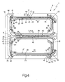
- device 40 comprises a rocker arm 41 fitted to a free end of pin 19, coaxially with axis 16, and having two arms 42, 43, each of which extends radially outwards from pin 19, and is fitted on a free end with a tappet roller 44, 45, which is mounted for rotation on relative arm 42, 43, and engages a relative fixed cam 46, 47 ( Figure 4) for controlling the angular position of rocker arm 41 and, therefore, of bar 14 about axis 16, and for oscillating bar 14 about axis 16 according to a given law.
- each cam 46, 47 comprises two separate portions 48, 49, which are located, with respect to portions 48, 49 of the other cam 46, 47, so that, along the straight portions of paths P1, P2, only one tappet roller 44, 45 engages relative cam 46, 47, i.e. the roller 44, 45 aligned with axis 16 in the travelling direction of sealing devices 12, 13 along relative paths P1, P2.
- electric motors 28 are powered by a power device 51 with sliding electric contacts, and which comprises a number of guides 52 of conducting material fitted to frame 26 and normally common to all of motors 28; and, for each motor 28, a number of brushes 53 also made of conducting material, and which are fitted to relative carriage 22, are equal in number to guides 52, and engage relative guides 52 in sliding manner as relative sealing device 12, 13 travels along relative path P1, P2.
- Sealing bars 14 and, therefore, relative surfaces 17a are powered by a power device 54 with sliding electric contacts, and which comprises a number of guides 55 of conducting material fitted to frame 26 and normally common to all of bars 14; and, for each bar 14, a number of brushes 56 also made of conducting material, and which are fitted to relative bar 14, are equal in number to guides 55, and engage relative guides 55 in sliding manner as relative sealing device 12, 13 travels along relative path P1, P2.
- devices 51 and 54 are also used to connect sealing devices 12, 13 to an electronic central control unit (not shown) for selectively controlling the position of carriages 22 along relative paths P1, P2, and the operating mode of bars 14.
- Sealing devices 12, 13 therefore have respective actuating devices 27 controlled independently by said electronic central control unit (not shown), and which provide for moving sealing devices 12, 13 along relative paths P1, P2 with independent laws of motion.
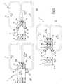
- each top sealing device 12 is fed at least along sealing path P in time with a corresponding bottom sealing device 13, and as of the instant in which, as shown in Figure 5a, the leading end of tubular wrapping 6 has been folded substantially onto a first product 2 (hereinafter indicated 2 1 ) to define one of relative overlap portions 4, and the same portion 4 has been stabilized by an end seal made by a first pair of devices 12, 13 (hereinafter indicated 12a, 13a) engaging the front of product 2 1 in direction 7.
- speed V2 of devices 12b and 13b is so controlled as to be lower than speed V1, so that, by combining speed V2 of product 2 1 with speed V1 of the next product 2 (hereinafter indicated 2 2 ) entering unit 9, and with the movement of devices 12b and 13b along relative paths P1, P2, the tubular portion 11 between products 2 1 and 2 2 can be folded gradually onto products 2 1 and 2 2 to define relative overlap portions 4, and product 2 2 can be moved into contact with devices 12b, 13b.
- the rear of product 2 2 in direction 7 is engaged by another pair of devices 12, 13 (hereinafter indicated 12c, 13c) so that, as products 2 1 and 2 2 travel along an intermediate portion of path P, the overlap portions 4 between products 2 1 and 2 2 are stabilized by devices 12b, 13b, and are also separated in known manner by a cutting member (not shown) housed in one of devices 12b, 13b, so as to cut sheet 3 of wrapping material of product 2 1 off wrapping 6.
- speed V2 is so controlled as to enable devices 12b, 13b to detach product 2 1 from product 2 2 .
- Tubular wrapping 6 and products 2 are therefore fed by wrapping unit 5 to input station 8 at a constant travelling speed V1, and products 2 are fed by sealing devices 12, 13 along sealing path P at a travelling speed V2 varying along path P.
Landscapes
- Engineering & Computer Science (AREA)
- Mechanical Engineering (AREA)
- Physics & Mathematics (AREA)
- Thermal Sciences (AREA)
- Package Closures (AREA)
- Containers And Plastic Fillers For Packaging (AREA)
Abstract
Description
- The present invention relates to a packaging machine for wrapping products in respective sheets of heat-seal wrapping material.
- More specifically, the present invention relates to a packaging machine for wrapping products, each defined by one or more articles. In the following description, the articles considered are groups of rolls of paper, to which the following description refers purely by way of example.
- Known machines for packaging rolls of paper, and of the type described, for example, in US Patent 5,433,063, normally comprise a wrapping unit for forming a tubular wrapping from a continuous web of heat-seal material; feeding groups of rolls of paper successively into the tubular wrapping, so that each group is located between two free tubular portions of the tubular wrapping; and transferring the tubular wrapping and the groups to a sealing station at a first constant travelling speed.
- The sealing station comprises at least two sealing units, each of which comprises at least two sealing bars moving in time with each other along a substantially horizontal sealing path to feed a group of rolls of paper along the sealing path and seal a said free tubular portion.
- The sealing bars of each sealing unit are mounted on two respective pairs of belt conveyors, which are located on opposite sides of the sealing path, in a substantially vertical direction crosswise to the sealing path, and which form part of a relative actuating device also comprising an electric motor common to all the belt conveyors of the actuating device.
- Each electric motor is operated independently of the electric motors of the other sealing units to feed the relative sealing bars, and hence the relative groups of rolls of paper, along the sealing path at a second travelling speed, which is variable so that, by combining the first and second travelling speed, each free tubular portion is folded substantially onto the relative groups of rolls of paper.
- Since the output rate is proportional to the number of sealing units employed, known packaging machines of the type described above are equipped with a relatively large number of sealing units, and consequently also with a relatively large number of belt conveyors, which make them relatively complex and expensive.
- It is an object of the present invention to provide a packaging machine for wrapping products in respective sheets of heat-seal wrapping material, designed to eliminate the aforementioned drawbacks.
- According to the present invention, there is provided a packaging machine for wrapping products in respective sheets of heat-seal wrapping material, the machine comprising wrapping means for forming a tubular wrapping from a continuous web of heat-seal material, and for feeding products successively into the tubular wrapping, each product being located between two free tubular portions of said tubular wrapping; and sealing and feed means comprising at least two pairs of sealing devices, the sealing devices in each pair of sealing devices being movable along a sealing path to feed a respective said product along the sealing path at a variable travelling speed, and perform a respective sealing operation on a respective said tubular portion; and being characterized by comprising actuating means for advancing said sealing devices with respective independent laws of motion.
- A non-limiting embodiment of the present invention will be described by way of example with reference to the accompanying drawings, in which:
- Figure 1 shows a schematic side view of a preferred embodiment of the packaging machine according to the present invention;
- Figure 2 shows a schematic view in perspective of a first detail in Figure 1;
- Figure 3 shows a schematic side view, with parts in section and parts removed for clarity, of a second detail in Figure 1;
- Figure 4 shows a schematic side view, with parts removed for clarity, of a third detail in Figure 1;
- Figure 5 shows a schematic side view of the operating principle of the Figure 1 packaging machine.
-
- With reference to Figures 1 and 2,
number 1 indicates as a whole a packaging machine for wrappingproducts 2 inrespective sheets 3 of transparent heat-seal material, each of which, in the finished configuration of the respective wrappedproduct 2, is folded about and substantially ontorespective product 2, and is stabilized by a longitudinal side seal along a longitudinal overlap portion (not shown) ofsheet 3, and by two end seals at respective transverse overlap portions 4 ofsheet 3. - As shown in Figure 2, each
product 2 is defined by six rolls ofpaper 2a arranged with theirlongitudinal axes 2b parallel. Obviously, in alternative embodiments not shown,rolls 2a defining eachproduct 2 are other than six in number and arranged otherwise than as shown in Figure 2. -
Machine 1 comprises a knownwrapping unit 5 for forming atubular wrapping 6 from a continuous web of transparent heat-seal material (not shown); stabilizingwrapping 6 by a longitudinal side seal along a longitudinal overlap portion (not shown) of wrapping 6;feeding products 2 successively inside wrapping 6; and feeding wrapping 6 andproducts 2 in a substantiallyhorizontal direction 7 and at a substantially constant travelling speed V1 to aninput station 8 of asealing unit 9. -
Products 2 are positioned inside wrapping 6 with theiraxes 2b parallel to a substantially vertical direction 10 crosswise todirection 7, and are equally spaced along wrapping 6 so that eachproduct 2 is located between two freetubular portions 11 of wrapping 6. Eachportion 11 is of a length, measured parallel todirection 7, equal to the height of aproduct 2, measured parallel to direction 10, plus twice the length of an overlap portion 4 measured parallel todirection 7. -
Unit 9 comprises a number of - in the example shown, six -top sealing devices 12 movable along an endless path P1 extending in a substantially vertical plane; and a number ofbottom sealing devices 13, which are equal in number todevices 12, cooperate withcorresponding devices 12, and are movable along an endless path P2 extending in the same plane as path P1, and having a horizontal portion in common with path P1 and defining a sealing path P. - With reference to Figure 3, each
device sealing bar 14, which extends in adirection 15 crosswise to relative path P1, P2, has alongitudinal axis 16 parallel todirection 15, and comprises a substantially parallelepiped-shaped, substantially rectangular-sectioncentral portion 17 having a heatedflat surface 17a of a width, measured parallel to path P, substantially equal to twice the length of an overlap portion 4 also measured parallel to path P (Figures 1 and 2). -
Bar 14 also comprises two substantiallycylindrical end pins portion 17 indirection 15, are coaxial withaxis 16, and respectively engage, in rotary and axially fixed manner, via the interposition of respective pairs ofrolling bearings 20, aninput gear 21a and anoutput gear 21c of agear train 21, which, in the example shown, comprises threegears carriage 22 for conveyingbar 14 along relative path P1, P2. - The
intermediate gear 21b is located betweengears longitudinal axis 23 substantially parallel toaxis 16, and is engaged in rotary and axially fixed manner, throughportion 17 and via the interposition of a pair ofrolling bearings 24, to rotate, with respect toportion 17, aboutaxis 23. -
Gears respective racks 25 fitted to afixed frame 26 ofmachine 1 and extending along relative path P1, P2, and are rotated aboutaxis 16 to movecarriage 22, and thereforebar 14, along relative path P1, P2 by means of an actuatingdevice 27 comprising anelectric motor 28 fixed to a substantially flat portion of a supportingmember 29.Member 29 forms part ofcarriage 22, and also comprises asleeve 30 coaxial withaxis 16 and engaged in rotary and axially fixed manner bypin 18 with the interposition of a pair ofrolling bearings 31. -
Motor 28 has anoutput shaft 32 mounted to rotate about a substantially longitudinal axis 33 parallel toaxis 16, and which is connected togear 21a by abelt drive 34 forming part ofdevice 27, and comprising apulley 35 fitted toshaft 32 and coaxial with axis 33, apulley 36 fitted togear 21a and coaxial withaxis 16, and abelt 37 looped aboutpulleys - To control the position of
carriage 22, and therefore ofbar 14, crosswise to relative path P1, P2, eachgear rolling bearings 38, each of which is fitted torelative gear axis 16, and engages arelative race 39 formed throughframe 26, extending parallel to relative path P1, P2, and of a height, measured crosswise to relative path P1, P2, greater than the outside diameter ofrelative bearing 38. On account of the difference in the size ofbearings 38 andrelative races 39, each bearing 38 contacts only one side ofrelative race 39, and so moves along relative path P1, P2 with a rotary-translational motion. - To control the angular position of
member 29 aboutaxis 16,member 29 has a supporting pin (not shown) extending indirection 15 and supporting a pair ofrolling bearings 29a (Figure 1), which engage theraces 39 ofgear 21a to preventmember 29 from rotating aboutaxis 16. - The angular position of
bar 14 and, therefore, ofsurface 17a aboutaxis 16 and with respect tocarriage 22 is controlled by anorienting device 40 for keepingsurface 17a substantially parallel to relative path P1, P2 at least along sealing path P. - With reference to Figures 1 and 3,
device 40 comprises arocker arm 41 fitted to a free end ofpin 19, coaxially withaxis 16, and having twoarms pin 19, and is fitted on a free end with atappet roller relative arm cam 46, 47 (Figure 4) for controlling the angular position ofrocker arm 41 and, therefore, ofbar 14 aboutaxis 16, and for oscillatingbar 14 aboutaxis 16 according to a given law. - As shown in Figure 4, each
cam separate portions portions other cam tappet roller relative cam roller axis 16 in the travelling direction ofsealing devices - In connection with the above, it should be pointed out that, at one of the curved portions of each path P1, P2,
relative cams intersection portion 50 where the angular position of eachrocker arm 41 aboutaxis 16 is controlled by a relative third tappet roller (not shown) engaging a third cam (not shown). - With reference to Figure 3,
electric motors 28 are powered by apower device 51 with sliding electric contacts, and which comprises a number ofguides 52 of conducting material fitted toframe 26 and normally common to all ofmotors 28; and, for eachmotor 28, a number ofbrushes 53 also made of conducting material, and which are fitted torelative carriage 22, are equal in number toguides 52, and engagerelative guides 52 in sliding manner asrelative sealing device -
Sealing bars 14 and, therefore,relative surfaces 17a are powered by apower device 54 with sliding electric contacts, and which comprises a number ofguides 55 of conducting material fitted toframe 26 and normally common to all ofbars 14; and, for eachbar 14, a number ofbrushes 56 also made of conducting material, and which are fitted torelative bar 14, are equal in number toguides 55, and engagerelative guides 55 in sliding manner asrelative sealing device - It should be pointed out that
devices sealing devices carriages 22 along relative paths P1, P2, and the operating mode ofbars 14. -
Sealing devices devices 27 controlled independently by said electronic central control unit (not shown), and which provide for movingsealing devices - Operation of
packaging machine 1 will now be described with reference to Figures 1 and 5, bearing in mind that eachtop sealing device 12 is fed at least along sealing path P in time with a correspondingbottom sealing device 13, and as of the instant in which, as shown in Figure 5a, the leading end oftubular wrapping 6 has been folded substantially onto a first product 2 (hereinafter indicated 21) to define one of relative overlap portions 4, and the same portion 4 has been stabilized by an end seal made by a first pair ofdevices 12, 13 (hereinafter indicated 12a, 13a) engaging the front ofproduct 21 indirection 7. - With reference to Figures 1 and 5b, the rear of
product 21 indirection 7 is engaged by another pair ofdevices 12, 13 (hereinafter indicated 12b, 13b) and fed along path P at a given travelling speed V2, while wrapping 6 and the followingproducts 2 are fed by wrappingunit 5 indirection 7 at speed V1. Along an initial portion of path P, speed V2 ofdevices product 21 with speed V1 of the next product 2 (hereinafter indicated 22) enteringunit 9, and with the movement ofdevices tubular portion 11 betweenproducts products product 22 can be moved into contact withdevices - As shown in Figure 5c, the rear of
product 22 indirection 7 is engaged by another pair ofdevices 12, 13 (hereinafter indicated 12c, 13c) so that, asproducts products devices devices sheet 3 of wrapping material ofproduct 21 off wrapping 6. - Finally, as shown in Figure 1, along a final portion of path P, speed V2 is so controlled as to enable
devices product 21 fromproduct 22. - The above operating sequence relative to
products new product 2 fed by wrappingunit 5 toinput station 8 ofsealing unit 9. -
Tubular wrapping 6 andproducts 2 are therefore fed by wrappingunit 5 toinput station 8 at a constant travelling speed V1, andproducts 2 are fed by sealingdevices
Claims (13)
- A packaging machine for wrapping products (2) in respective sheets (3) of heat-seal wrapping material, the machine comprising wrapping means (5) for forming a tubular wrapping (6) from a continuous web of heat-seal material, and for feeding products (2) successively into the tubular wrapping (6), each product (2) being located between two free tubular portions (11) of said tubular wrapping (6); and sealing and feed means (9) comprising at least two pairs of sealing devices (12, 13), the sealing devices (12, 13) in each pair of sealing devices (12, 13) being movable along a sealing path (P) to feed a respective said product (2) along the sealing path (P) at a variable travelling speed (V2), and perform a respective sealing operation on a respective said tubular portion (11); and being characterized by comprising actuating means (27) for advancing said sealing devices (12, 13) with respective independent laws of motion.
- A packaging machine as claimed in Claim 1, wherein said actuating means (27) comprise an actuating device (28) for each said sealing device (12, 13); logic control means being provided to selectively control said actuating devices (28) independently of each other.
- A packaging machine as claimed in Claim 1 or 2, wherein each sealing device (12, 13) has a heated surface (17a); orienting means (40) being provided to keep said heated surface (17a) substantially parallel to said sealing path (P) along the sealing path (P) itself.
- A packaging machine as claimed in Claim 3, wherein each sealing device (12, 13) comprises a carriage (22) movable along said sealing path (P); and a sealing bar (14) having said heated surface (17a) and connected to the carriage (22) to oscillate, with respect to the carriage (22), about a relative axis (16) and under the control of said orienting means (40).
- A packaging machine as claimed in Claim 4, wherein said orienting means (40) comprise cam means (46, 47); and at least one tappet (44, 45) carried by said sealing bar (14) and cooperating with said cam means (46, 47) to control the angular position of the sealing bar (14) about said axis (16).
- A packaging machine as claimed in Claim 4 or 5, and also comprising two racks (25) substantially parallel to each other and to said sealing path (P); the carriage (22) comprising a gear train (21), in turn comprising an input gear and an output gear (21a, 21c), each meshing with a relative said rack (25), and an intermediate gear (21b) interposed between the input gear and the output gear (21a, 21c).
- A packaging machine as claimed in Claim 6, wherein said actuating means (27) comprise, for each said carriage (22), an electric motor (28) for operating the relative said input gear (21a).
- A packaging machine as claimed in Claim 7, wherein said actuating means (27) also comprise power means (51) for supplying electric power to said electric motors (28); said power means (51) being power means (51) with sliding electric contacts.
- A packaging machine as claimed in Claim 8, wherein said power means (51) with sliding electric contacts comprise at least one fixed first guide (52) made of conducting material; and, for each said electric motor (28), at least one first sliding brush (53) also made of conducting material, and which is carried by the relative electric motor (28) and engages said first guide (52) in sliding manner.
- A packaging machine as claimed in any one of Claims 3 to 9, and also comprising further power means (54) for supplying electric power to said heated surfaces (17a); said further power means (54) being power means (54) with sliding electric contacts.
- A packaging machine as claimed in Claim 10, wherein said further power means (54) with sliding electric contacts comprise at least one fixed second guide (55) made of conducting material; and, for each said heated surface (17a), at least one second sliding brush (56) also made of conducting material, and which is carried by the relative sealing device (12, 13) and engages said second guide (55) in sliding manner.
- A packaging machine as claimed in any one of the foregoing Claims, and also comprising at least one third guide (39) extending along said sealing path (P); each sealing device (12, 13) having connecting means (38) for connection to said third guide (39) and for controlling the position of the sealing device (12, 13) in a direction crosswise to the sealing path (P).
- A packaging machine as claimed in Claim 12, wherein said connecting means (38) comprise two connecting members (38) mounted for rotation o the relative sealing device (12, 13); the connecting members (38) and the third guide (39) being so formed that the connecting members (38) move along the third guide (39) with a rotary-translational motion.
Priority Applications (5)
| Application Number | Priority Date | Filing Date | Title |
|---|---|---|---|
| ES03425052.2T ES2576427T3 (en) | 2003-01-31 | 2003-01-31 | Packaging machine to wrap products in respective sheets of heat-sealable wrapping material |
| EP03425052.2A EP1442984B1 (en) | 2003-01-31 | 2003-01-31 | Packaging machine for wrapping products in respective sheets of heat-seal wrapping material |
| CA2456354A CA2456354C (en) | 2003-01-31 | 2004-01-28 | Packaging machine for wrapping products in respective sheets of heat-seal wrapping material |
| US10/767,535 US6907716B2 (en) | 2003-01-31 | 2004-01-29 | Packaging machine for wrapping products in respective sheets of heat-seal wrapping material |
| BR0400623-2A BRPI0400623A (en) | 2003-01-31 | 2004-01-30 | Packaging Machine for Packing Products with Heat Shrink Packaging Sheets |
Applications Claiming Priority (1)
| Application Number | Priority Date | Filing Date | Title |
|---|---|---|---|
| EP03425052.2A EP1442984B1 (en) | 2003-01-31 | 2003-01-31 | Packaging machine for wrapping products in respective sheets of heat-seal wrapping material |
Publications (2)
| Publication Number | Publication Date |
|---|---|
| EP1442984A1 true EP1442984A1 (en) | 2004-08-04 |
| EP1442984B1 EP1442984B1 (en) | 2016-04-27 |
Family
ID=32605499
Family Applications (1)
| Application Number | Title | Priority Date | Filing Date |
|---|---|---|---|
| EP03425052.2A Expired - Lifetime EP1442984B1 (en) | 2003-01-31 | 2003-01-31 | Packaging machine for wrapping products in respective sheets of heat-seal wrapping material |
Country Status (5)
| Country | Link |
|---|---|
| US (1) | US6907716B2 (en) |
| EP (1) | EP1442984B1 (en) |
| BR (1) | BRPI0400623A (en) |
| CA (1) | CA2456354C (en) |
| ES (1) | ES2576427T3 (en) |
Cited By (10)
| Publication number | Priority date | Publication date | Assignee | Title |
|---|---|---|---|---|
| EP2983994A4 (en) * | 2013-04-08 | 2016-12-21 | Alain Cerf | Multiple sealing bars for film wrapping |
| EP3254975A1 (en) * | 2016-06-09 | 2017-12-13 | Altopack S.P.A. | Packaging machine for long food pasta or similar products with formation of single packages of pasta or other, equipped with transverse flap closing |
| WO2020005643A1 (en) * | 2018-06-29 | 2020-01-02 | Sealed Air Corporation (Us) | End seal carriage velocity differential |
| US11638504B2 (en) | 2020-03-16 | 2023-05-02 | Gpcp Ip Holdings Llc | Paper wraps, paper wrapped products, and methods of making the same |
| IT202200019440A1 (en) | 2022-09-22 | 2024-03-22 | Valmet Tissue Converting S P A | PACKAGING MACHINE WITH SEALING MATERIAL DISPENSING DEVICE |
| WO2024061845A1 (en) | 2022-09-22 | 2024-03-28 | Valmet Tissue Converting S.P.A. | Packaging machine with sealing device for paper wrapping materials |
| IT202300000063A1 (en) | 2023-01-04 | 2024-07-04 | Valmet Tissue Converting S P A | PACKAGING MACHINE WITH HEATED FOLDERS AND METHOD |
| IT202300022413A1 (en) | 2023-10-26 | 2025-04-26 | Valmet Tissue Converting S P A | SEALING DEVICE FOR FILM-WRAPPED PRODUCT PACKAGE SEALING MACHINES |
| IT202300022443A1 (en) | 2023-10-26 | 2025-04-26 | Valmet Tissue Converting S P A | SEALING MACHINE |
| IT202300022428A1 (en) | 2023-10-26 | 2025-04-26 | Valmet Tissue Converting S P A | SEALING BODY |
Families Citing this family (6)
| Publication number | Priority date | Publication date | Assignee | Title |
|---|---|---|---|---|
| DE60310952T2 (en) * | 2003-11-28 | 2007-11-15 | Kpl Packaging S.P.A. | Packaging machine for wrapping objects in packaging films of heat-sealable material |
| EP1535843B1 (en) * | 2003-11-28 | 2007-10-10 | KPL Packaging S.p.A. | Packaging machine for wrapping products in respective sheets of heat-seal wrapping material |
| ITBO20050480A1 (en) * | 2005-07-19 | 2007-01-20 | Gd Spa | METHOD AND DEVICE FOR THE ARRANGEMENT OF ARTICLES |
| CN109398788B (en) * | 2017-08-18 | 2023-08-25 | 北新集团建材股份有限公司 | Control method for automatic packaging of plates |
| US11834211B2 (en) | 2019-09-19 | 2023-12-05 | Korber Tissue S.p.A. | Packing machine for paper product converting line and method for packing of paper products |
| US10781941B1 (en) | 2019-12-18 | 2020-09-22 | Trinity Bay Equipment Holdings, LLC | Pipeline retainer stake systems and methods |
Citations (3)
| Publication number | Priority date | Publication date | Assignee | Title |
|---|---|---|---|---|
| US5433063A (en) * | 1993-04-29 | 1995-07-18 | Hayssen Manufacturing Company | Sealing system and process for packaging machine |
| DE10020324A1 (en) * | 1999-04-26 | 2000-11-30 | Internat Paper Company New Yor | Conditioning machine for filling, sealing and cutting parallelepiped containers with juice or milk comprises groups of carriages, driven independently from each other, and each having sealing jaws |
| EP1157930A2 (en) * | 2000-05-25 | 2001-11-28 | Paper Converting Machine Company | Sealing apparatus and method for packaging machine |
Family Cites Families (3)
| Publication number | Priority date | Publication date | Assignee | Title |
|---|---|---|---|---|
| JPS6011347A (en) * | 1983-06-30 | 1985-01-21 | 株式会社古川製作所 | Method and device for making bag |
| US4702060A (en) * | 1986-06-26 | 1987-10-27 | Uni-Pak Film Systems, Inc. | Adjustable packaging device |
| US4905446A (en) * | 1988-11-25 | 1990-03-06 | Apv Crepaco, Inc. | Apparatus for wrapping articles |
-
2003
- 2003-01-31 EP EP03425052.2A patent/EP1442984B1/en not_active Expired - Lifetime
- 2003-01-31 ES ES03425052.2T patent/ES2576427T3/en not_active Expired - Lifetime
-
2004
- 2004-01-28 CA CA2456354A patent/CA2456354C/en not_active Expired - Fee Related
- 2004-01-29 US US10/767,535 patent/US6907716B2/en not_active Expired - Lifetime
- 2004-01-30 BR BR0400623-2A patent/BRPI0400623A/en not_active Application Discontinuation
Patent Citations (3)
| Publication number | Priority date | Publication date | Assignee | Title |
|---|---|---|---|---|
| US5433063A (en) * | 1993-04-29 | 1995-07-18 | Hayssen Manufacturing Company | Sealing system and process for packaging machine |
| DE10020324A1 (en) * | 1999-04-26 | 2000-11-30 | Internat Paper Company New Yor | Conditioning machine for filling, sealing and cutting parallelepiped containers with juice or milk comprises groups of carriages, driven independently from each other, and each having sealing jaws |
| EP1157930A2 (en) * | 2000-05-25 | 2001-11-28 | Paper Converting Machine Company | Sealing apparatus and method for packaging machine |
Cited By (14)
| Publication number | Priority date | Publication date | Assignee | Title |
|---|---|---|---|---|
| EP2983994A4 (en) * | 2013-04-08 | 2016-12-21 | Alain Cerf | Multiple sealing bars for film wrapping |
| EP3254975A1 (en) * | 2016-06-09 | 2017-12-13 | Altopack S.P.A. | Packaging machine for long food pasta or similar products with formation of single packages of pasta or other, equipped with transverse flap closing |
| US12157597B2 (en) * | 2018-06-29 | 2024-12-03 | Sealed Air Corporation (Us) | End seal carriage velocity differential |
| US20210269182A1 (en) * | 2018-06-29 | 2021-09-02 | Sealed Air Corporation (Us) | End seal carriage velocity differential |
| WO2020005643A1 (en) * | 2018-06-29 | 2020-01-02 | Sealed Air Corporation (Us) | End seal carriage velocity differential |
| US11638504B2 (en) | 2020-03-16 | 2023-05-02 | Gpcp Ip Holdings Llc | Paper wraps, paper wrapped products, and methods of making the same |
| IT202200019440A1 (en) | 2022-09-22 | 2024-03-22 | Valmet Tissue Converting S P A | PACKAGING MACHINE WITH SEALING MATERIAL DISPENSING DEVICE |
| WO2024061845A1 (en) | 2022-09-22 | 2024-03-28 | Valmet Tissue Converting S.P.A. | Packaging machine with sealing device for paper wrapping materials |
| WO2024061846A2 (en) | 2022-09-22 | 2024-03-28 | Valmet Tissue Converting S.P.A. | Packaging machine with sealant dispensing device |
| IT202300000063A1 (en) | 2023-01-04 | 2024-07-04 | Valmet Tissue Converting S P A | PACKAGING MACHINE WITH HEATED FOLDERS AND METHOD |
| IT202300022413A1 (en) | 2023-10-26 | 2025-04-26 | Valmet Tissue Converting S P A | SEALING DEVICE FOR FILM-WRAPPED PRODUCT PACKAGE SEALING MACHINES |
| IT202300022443A1 (en) | 2023-10-26 | 2025-04-26 | Valmet Tissue Converting S P A | SEALING MACHINE |
| IT202300022428A1 (en) | 2023-10-26 | 2025-04-26 | Valmet Tissue Converting S P A | SEALING BODY |
| EP4545279A1 (en) | 2023-10-26 | 2025-04-30 | Valmet Tissue Converting S.p.A. | Sealing machine |
Also Published As
| Publication number | Publication date |
|---|---|
| CA2456354C (en) | 2010-12-21 |
| BRPI0400623A (en) | 2005-01-11 |
| US6907716B2 (en) | 2005-06-21 |
| CA2456354A1 (en) | 2004-07-31 |
| ES2576427T3 (en) | 2016-07-07 |
| EP1442984B1 (en) | 2016-04-27 |
| US20040226269A1 (en) | 2004-11-18 |
Similar Documents
| Publication | Publication Date | Title |
|---|---|---|
| CA2456354C (en) | Packaging machine for wrapping products in respective sheets of heat-seal wrapping material | |
| CN111655585B (en) | Continuous motion packaging machine with carton turning station | |
| EP1535843B1 (en) | Packaging machine for wrapping products in respective sheets of heat-seal wrapping material | |
| EP2001772B1 (en) | Device for forming a continuous flow of oriented products | |
| KR20170124645A (en) | Method and device for conveying and rotating flat objects | |
| JP2006321567A (en) | Continuously operating packaging device | |
| EP2254816B1 (en) | A unit for transferring products | |
| CN101186121B (en) | Machine for producing sheet products | |
| US5203144A (en) | Machines for packaging articles with heat-shrinking material | |
| EP2736825B1 (en) | Article orienting machine | |
| JP5057878B2 (en) | End seal device, packaging machine using the same, and pillow packaging machine | |
| CN108248930A (en) | The film of product wraps up in packet heat-sealing device and the film of product wraps up in packet heat-sealing method | |
| EP1602601A1 (en) | Container carrying conveyor apparatus | |
| EP0706941A2 (en) | Continuous cigarette manufacturing machine | |
| JP4247522B2 (en) | Assortment equipment | |
| CN109532105B (en) | Transmission structure of paper bag arranging and finishing device | |
| US7269931B2 (en) | Overwrapping machine for packets of cigarettes | |
| EP1470067A1 (en) | Device to modify the pitch between pushers according to the length of the product | |
| EP0611696A2 (en) | Compacting unit for groups of flat products arranged side by side on edge | |
| CN214988065U (en) | Box scraper blade moves machine of carrying | |
| JP3030858U (en) | Transport tool that works with the seal bar | |
| EP0706942B1 (en) | Continuous cigarette manufacturing machine | |
| EP1780127A1 (en) | Packing wheel | |
| JP2019172382A (en) | Article guide device | |
| JPH08108959A (en) | Divided carrier conveyor |
Legal Events
| Date | Code | Title | Description |
|---|---|---|---|
| PUAI | Public reference made under article 153(3) epc to a published international application that has entered the european phase |
Free format text: ORIGINAL CODE: 0009012 |
|
| AK | Designated contracting states |
Kind code of ref document: A1 Designated state(s): AT BE BG CH CY CZ DE DK EE ES FI FR GB GR HU IE IT LI LU MC NL PT SE SI SK TR |
|
| AX | Request for extension of the european patent |
Extension state: AL LT LV MK RO |
|
| 17P | Request for examination filed |
Effective date: 20050203 |
|
| AKX | Designation fees paid |
Designated state(s): DE ES FR GB IT |
|
| RAP1 | Party data changed (applicant data changed or rights of an application transferred) |
Owner name: KPL PACKAGING S.P.A. |
|
| 17Q | First examination report despatched |
Effective date: 20081029 |
|
| RAP1 | Party data changed (applicant data changed or rights of an application transferred) |
Owner name: FABIO PERINI PACKAGING S.P.A. |
|
| RAP1 | Party data changed (applicant data changed or rights of an application transferred) |
Owner name: FABIO PERINI S.P.A. |
|
| GRAP | Despatch of communication of intention to grant a patent |
Free format text: ORIGINAL CODE: EPIDOSNIGR1 |
|
| INTG | Intention to grant announced |
Effective date: 20151110 |
|
| RIN1 | Information on inventor provided before grant (corrected) |
Inventor name: GORRIERI, GIORDANO Inventor name: CINOTTI, ANDREA |
|
| GRAS | Grant fee paid |
Free format text: ORIGINAL CODE: EPIDOSNIGR3 |
|
| GRAA | (expected) grant |
Free format text: ORIGINAL CODE: 0009210 |
|
| AK | Designated contracting states |
Kind code of ref document: B1 Designated state(s): DE ES FR GB IT |
|
| REG | Reference to a national code |
Ref country code: GB Ref legal event code: FG4D |
|
| REG | Reference to a national code |
Ref country code: DE Ref legal event code: R096 Ref document number: 60348872 Country of ref document: DE |
|
| REG | Reference to a national code |
Ref country code: ES Ref legal event code: FG2A Ref document number: 2576427 Country of ref document: ES Kind code of ref document: T3 Effective date: 20160707 |
|
| REG | Reference to a national code |
Ref country code: FR Ref legal event code: PLFP Year of fee payment: 15 |
|
| REG | Reference to a national code |
Ref country code: DE Ref legal event code: R097 Ref document number: 60348872 Country of ref document: DE |
|
| PLBE | No opposition filed within time limit |
Free format text: ORIGINAL CODE: 0009261 |
|
| STAA | Information on the status of an ep patent application or granted ep patent |
Free format text: STATUS: NO OPPOSITION FILED WITHIN TIME LIMIT |
|
| 26N | No opposition filed |
Effective date: 20170130 |
|
| REG | Reference to a national code |
Ref country code: FR Ref legal event code: PLFP Year of fee payment: 16 |
|
| PG25 | Lapsed in a contracting state [announced via postgrant information from national office to epo] |
Ref country code: IT Free format text: LAPSE BECAUSE OF NON-PAYMENT OF DUE FEES Effective date: 20170131 |
|
| PGFP | Annual fee paid to national office [announced via postgrant information from national office to epo] |
Ref country code: GB Payment date: 20190130 Year of fee payment: 17 Ref country code: FR Payment date: 20190128 Year of fee payment: 17 Ref country code: ES Payment date: 20190225 Year of fee payment: 17 |
|
| PGFP | Annual fee paid to national office [announced via postgrant information from national office to epo] |
Ref country code: DE Payment date: 20190401 Year of fee payment: 17 |
|
| REG | Reference to a national code |
Ref country code: DE Ref legal event code: R119 Ref document number: 60348872 Country of ref document: DE |
|
| GBPC | Gb: european patent ceased through non-payment of renewal fee |
Effective date: 20200131 |
|
| PG25 | Lapsed in a contracting state [announced via postgrant information from national office to epo] |
Ref country code: DE Free format text: LAPSE BECAUSE OF NON-PAYMENT OF DUE FEES Effective date: 20200801 Ref country code: GB Free format text: LAPSE BECAUSE OF NON-PAYMENT OF DUE FEES Effective date: 20200131 Ref country code: FR Free format text: LAPSE BECAUSE OF NON-PAYMENT OF DUE FEES Effective date: 20200131 |
|
| REG | Reference to a national code |
Ref country code: ES Ref legal event code: FD2A Effective date: 20210604 |
|
| PG25 | Lapsed in a contracting state [announced via postgrant information from national office to epo] |
Ref country code: ES Free format text: LAPSE BECAUSE OF NON-PAYMENT OF DUE FEES Effective date: 20200201 |