EP1442890A1 - Liquid supplying member, method of manufacturing the same, and liquid ejection apparatus incorporating the same - Google Patents
Liquid supplying member, method of manufacturing the same, and liquid ejection apparatus incorporating the same Download PDFInfo
- Publication number
- EP1442890A1 EP1442890A1 EP03018761A EP03018761A EP1442890A1 EP 1442890 A1 EP1442890 A1 EP 1442890A1 EP 03018761 A EP03018761 A EP 03018761A EP 03018761 A EP03018761 A EP 03018761A EP 1442890 A1 EP1442890 A1 EP 1442890A1
- Authority
- EP
- European Patent Office
- Prior art keywords
- liquid
- liquid supplying
- set forth
- supplying member
- base member
- Prior art date
- Legal status (The legal status is an assumption and is not a legal conclusion. Google has not performed a legal analysis and makes no representation as to the accuracy of the status listed.)
- Granted
Links
- 239000007788 liquid Substances 0.000 title claims abstract description 193
- 238000004519 manufacturing process Methods 0.000 title claims description 13
- -1 polypropylene Polymers 0.000 claims description 18
- 229910052751 metal Inorganic materials 0.000 claims description 13
- 239000002184 metal Substances 0.000 claims description 13
- 229920002725 thermoplastic elastomer Polymers 0.000 claims description 10
- 239000004698 Polyethylene Substances 0.000 claims description 8
- 229920000573 polyethylene Polymers 0.000 claims description 8
- 239000004743 Polypropylene Substances 0.000 claims description 7
- 229920001155 polypropylene Polymers 0.000 claims description 7
- 239000004952 Polyamide Substances 0.000 claims description 3
- 238000005304 joining Methods 0.000 claims description 3
- 229920002647 polyamide Polymers 0.000 claims description 3
- 229920000139 polyethylene terephthalate Polymers 0.000 claims description 3
- 239000005020 polyethylene terephthalate Substances 0.000 claims description 3
- 238000000034 method Methods 0.000 claims description 2
- 239000010410 layer Substances 0.000 description 24
- 239000000463 material Substances 0.000 description 8
- 238000001746 injection moulding Methods 0.000 description 7
- 239000004033 plastic Substances 0.000 description 7
- 229920003023 plastic Polymers 0.000 description 7
- 239000003086 colorant Substances 0.000 description 5
- 238000001704 evaporation Methods 0.000 description 5
- 239000002904 solvent Substances 0.000 description 5
- 238000003466 welding Methods 0.000 description 5
- 230000002787 reinforcement Effects 0.000 description 4
- 230000008020 evaporation Effects 0.000 description 3
- 230000004048 modification Effects 0.000 description 3
- 238000012986 modification Methods 0.000 description 3
- 229920002742 polystyrene-block-poly(ethylene/propylene) -block-polystyrene Polymers 0.000 description 3
- 239000011241 protective layer Substances 0.000 description 3
- 238000000018 DNA microarray Methods 0.000 description 2
- 239000005662 Paraffin oil Substances 0.000 description 2
- 238000012856 packing Methods 0.000 description 2
- 230000000149 penetrating effect Effects 0.000 description 2
- 229920000642 polymer Polymers 0.000 description 2
- 238000009877 rendering Methods 0.000 description 2
- 239000000126 substance Substances 0.000 description 2
- XLYOFNOQVPJJNP-UHFFFAOYSA-N water Substances O XLYOFNOQVPJJNP-UHFFFAOYSA-N 0.000 description 2
- 239000004793 Polystyrene Substances 0.000 description 1
- 239000004902 Softening Agent Substances 0.000 description 1
- 229910052782 aluminium Inorganic materials 0.000 description 1
- XAGFODPZIPBFFR-UHFFFAOYSA-N aluminium Chemical compound [Al] XAGFODPZIPBFFR-UHFFFAOYSA-N 0.000 description 1
- 238000005452 bending Methods 0.000 description 1
- 230000015572 biosynthetic process Effects 0.000 description 1
- 238000004040 coloring Methods 0.000 description 1
- 239000013013 elastic material Substances 0.000 description 1
- 229920001971 elastomer Polymers 0.000 description 1
- 239000000806 elastomer Substances 0.000 description 1
- 239000007772 electrode material Substances 0.000 description 1
- 239000011888 foil Substances 0.000 description 1
- 230000001771 impaired effect Effects 0.000 description 1
- 239000004973 liquid crystal related substance Substances 0.000 description 1
- 239000012466 permeate Substances 0.000 description 1
- 229920002223 polystyrene Polymers 0.000 description 1
- 238000002360 preparation method Methods 0.000 description 1
- 230000003014 reinforcing effect Effects 0.000 description 1
Images





Classifications
-
- B—PERFORMING OPERATIONS; TRANSPORTING
- B41—PRINTING; LINING MACHINES; TYPEWRITERS; STAMPS
- B41J—TYPEWRITERS; SELECTIVE PRINTING MECHANISMS, i.e. MECHANISMS PRINTING OTHERWISE THAN FROM A FORME; CORRECTION OF TYPOGRAPHICAL ERRORS
- B41J2/00—Typewriters or selective printing mechanisms characterised by the printing or marking process for which they are designed
- B41J2/005—Typewriters or selective printing mechanisms characterised by the printing or marking process for which they are designed characterised by bringing liquid or particles selectively into contact with a printing material
- B41J2/01—Ink jet
- B41J2/17—Ink jet characterised by ink handling
- B41J2/175—Ink supply systems ; Circuit parts therefor
-
- B—PERFORMING OPERATIONS; TRANSPORTING
- B41—PRINTING; LINING MACHINES; TYPEWRITERS; STAMPS
- B41J—TYPEWRITERS; SELECTIVE PRINTING MECHANISMS, i.e. MECHANISMS PRINTING OTHERWISE THAN FROM A FORME; CORRECTION OF TYPOGRAPHICAL ERRORS
- B41J2/00—Typewriters or selective printing mechanisms characterised by the printing or marking process for which they are designed
- B41J2/005—Typewriters or selective printing mechanisms characterised by the printing or marking process for which they are designed characterised by bringing liquid or particles selectively into contact with a printing material
- B41J2/01—Ink jet
- B41J2/17—Ink jet characterised by ink handling
- B41J2/175—Ink supply systems ; Circuit parts therefor
- B41J2/17503—Ink cartridges
- B41J2/17506—Refilling of the cartridge
- B41J2/17509—Whilst mounted in the printer
-
- B—PERFORMING OPERATIONS; TRANSPORTING
- B41—PRINTING; LINING MACHINES; TYPEWRITERS; STAMPS
- B41J—TYPEWRITERS; SELECTIVE PRINTING MECHANISMS, i.e. MECHANISMS PRINTING OTHERWISE THAN FROM A FORME; CORRECTION OF TYPOGRAPHICAL ERRORS
- B41J29/00—Details of, or accessories for, typewriters or selective printing mechanisms not otherwise provided for
- B41J29/02—Framework
Definitions
- the invention relates to a liquid supplying member for supplying liquid contained in a liquid cartridge to a liquid ejection apparatus for effecting recording or printing operation.
- the invention also relates to a method of manufacturing such a liquid supplying member.
- the liquid ejection apparatus such as an ink jet recording apparatus, subjects an object to recording or printing by ejecting liquid to the object while a liquid ejection head is reciprocally actuated.
- Liquid to be ejected to the object e.g., ink
- a liquid container e.g., a liquid cartridge
- a liquid ejection head e.g., a recording head
- a liquid ejection apparatus of another type having only a liquid ejection head mounted on a carriage is also available as disclosed in Japanese Patent Publication No. 2001-212974A, for example.
- the liquid ejection apparatus When the carriage is equipped with only the liquid ejection head, the liquid ejection apparatus must be provided with a liquid supplying member for supplying liquid from the liquid container to the liquid ejection head.
- a liquid supplying member for supplying liquid from the liquid container to the liquid ejection head.
- a polyethylene tube has hitherto been used as such a liquid supplying member.
- a liquid supplying member for supplying liquid from a liquid container to a liquid ejection head provided in a liquid ejection apparatus, the liquid supplying member comprising:
- each of the first grooves is formed with a through hole extending to a second face of the base member which is opposite to the first face.
- the liquid supplying member can be routed in a compact manner within the liquid ejection apparatus. Accordingly, the liquid ejection apparatus can be made compact.
- the base member is comprised of a thermoplastic elastomer.
- injection molding can be adopted to form the base member. Consequently, the liquid supplying member can be manufactured inexpensively, and alternatives of shape of the liquid supplying member can be easily increased.
- the thermoplastic elastomer is comprised of polypropylene
- the first plate member comprises a first layer which is joined to the first face of the base member and comprised of at least one of polypropylene and polyethylene.
- the base member and the first plate member can be welded together.
- the first plate member comprises a second layer comprised of metal.
- the metal layer prevents evaporation of the liquid.
- the metal layer prevents intrusion of outside air into liquid.
- the first plate member comprises a third layer comprised of polyamide and a fourth layer comprised of polyethylene terephthalate, between which the second layer is sandwiched. In this case, not only the metal layer is protected, but also the strength of the first plate member is enhanced.
- the liquid supplying member may further comprise a second flexible plate member which is joined to a part of the second face and comprised of a metal layer. In this case, even when liquid has permeated through the base member, the metal layer prevents evaporation of liquid.
- the liquid supplying member comprises a first portion to be flexed and a second portion not to be flexed; and the first portion has a first thickness and the second portion has a second thickness thicker than the first thickness.
- the liquid supplying member can be readily flexed, while the quantity of liquid permeating through the base member in the thickness direction becomes smaller.
- a portion of the base member corresponding to at least the first portion has a cross section curved in a direction that the liquid supplying member is to be flexed.
- the liquid supplying member can be routed in the liquid ejection apparatus more compactly.
- the second face of the base member is formed with a plurality of second grooves arranged side by side in the first direction and sealed by a second flexible plate member.
- each one of the first grooves is communicated with associated one of the second grooves.
- each of the second grooves is formed with a through hole extending to the first face.
- the liquid supplying member may further comprise a connector having a higher rigidity than the base member and communicating the first grooves and the liquid ejection head. In this case, attachment of the liquid supplying member is performed easily.
- a cross-sectional area of each of the first grooves may be partly changed.
- the channel can be given a small cross-sectional area in only a portion of the liquid supplying member which is to be passed through a narrow area, thereby rendering the cross-sectional area of the liquid supplying member small.
- the base member is curved such that both longitudinal ends are opposed to each other in the vicinity of a longitudinal center portion thereof, in an original state.
- injection molding can be preferably adopted to form the base member.
- a liquid supplying member for supplying liquid from a liquid container to a liquid ejection head provided in a liquid ejection apparatus, the method comprising steps of:
- the liquid supplying member can be manufactured inexpensively.
- the mold is configured such that the base member is curved such that both longitudinal ends are opposed to each other in the vicinity of a longitudinal center portion thereof; and the thermoplastic elastomer is injected from portions of the mold corresponding to the both longitudinal ends and the longitudinal center portion.
- the base member can be formed through injection molding.
- a liquid ejection apparatus in which the above liquid supplying member is extended from the liquid container to the liquid ejection head.
- the liquid supplying member is flexed such that either one of the base member or the first plate member having a higher elasticity than the other faces inwards.
- the bending direction is preferably a direction in which any one having higher elasticity from among the base member and the elongated plate member becomes contracted. Such a configuration enables an improvement in durability of the liquid supplying member.
- an ink jet recording apparatus 10 is provided with: a carriage 42 which reciprocally travels so as to straddle a recorded object; a recording head 44 which is mounted on the carriage 42 and subjects the object to recording, writing, or printing by ejecting a plurality of colors of ink to the object; a plurality of cartridges 45 which contains different colors of ink therein; and a liquid supplying member 100.
- the carriage 42 is reciprocally moved along a guide shaft 48 by an unillustrated motor.
- the cartridges 45 are fixed not to the carriage 42 but to the main body of the ink jet recording apparatus 10.
- the liquid supplying member 100 is made of plastic material (e.g., thermoplastic elastomer) and formed with a required number of channels (a plurality of channels in the embodiment) to supply a plurality of colors of ink held in the respective cartridges 45 to the recording head 44 that travels back and forth.
- the recording head 44 ejects ink to the object 11 located below a travel path of the recording head 44, to thus perform recording, writing, or printing operation.
- the plurality of colors of ink held in the cartridges 45 are supplied to one end 100a (see Fig. 5) of the liquid supplying member 100 by way of unillustrated stationary channels.
- the liquid supplying member 100 becomes softer than the polyethylene tube.
- the liquid supplying member 100 can be folded largely, to thereby render the ink jet recording apparatus 10 particularly compact.
- the load exerted on a motor which drives the carriage 42 becomes smaller.
- the ink jet recording apparatus 10 is an example of the liquid ejection apparatus. Further, the recording head 44 of the ink jet recording apparatus is an example of a liquid ejection head of the liquid ejection apparatus, and the cartridges 45 are examples of a liquid container.
- Another example of the liquid ejection apparatus corresponds to a color filter manufacturing apparatus to be used for manufacturing a color filter of a liquid-crystal display.
- a coloring material ejection head of the apparatus is an example of the liquid ejection head.
- Another example of the liquid ejection apparatus is an electrode formation apparatus for forming electrodes, such as those of an organic EL display or those of a FED (Field Emission Display).
- an electrode material (a conductive paste) ejection head of the apparatus is an example of the liquid ejection head.
- Still another example of the liquid ejection apparatus is a biochip manufacturing apparatus for manufacturing a biochip.
- a bio-organic substance ejection head of the apparatus and a sample ejection head serving as a precision pipette correspond to examples of the liquid ejection head.
- the liquid ejection apparatus of the invention includes other industrial liquid ejection apparatuses of industrial application.
- the object 11 is a substance to be subjected to recording, writing, or printing as a result of ejection of liquid.
- the object includes recording paper, a circuit board on which a circuit pattern such as electrodes of a display are printed, a CD-ROM on which a label is printed, and a preparation on which a DNA circuit is to be printed.
- the liquid supplying member 100 comprises a base member 110 made of plastic material, and an elongated plate member 120 joined to one face 110a of the base member 110 by, e.g., adhesion or welding. While being joined to the base member 110, the elongated plate member 120 has flexibility.
- the base member 110 is formed with a plurality of elongated ridges 111 defining a plurality of individual grooves 112 each having rectangular cross section and arranged in a width direction of the base member 110. Open side of the grooves 112 are covered with the elongated plate member 112 to form a plurality of individual ink supplying channels.
- Such a structure enables manufacture of the liquid supplying member 100 by injecting plastic material (e.g., a thermoplastic elastomer) into a mold, to thereby mold the base member 110.
- plastic material e.g., a thermoplastic elastomer
- the base member 110 can be formed into a complicated geometry, and manufacturing costs can be reduced.
- the plastic material constituting the liquid supplying member 100 preferably includes paraffin oil serving as a softening agent. Further, the plastic material may contain polypropylene along with or separately from the paraffin oil.
- ridges 111 ones provided at both widthwise ends of the base member 110 are wider than the remaining ridges 111.
- ink solvent e.g., water
- the elongated plate member 120 has a multilayer structure in which a welding layer 121, a reinforcement layer 122, a metal layer 123, and a protective layer 124 are laminated, in the order given from the base member 110.
- the welding layer 121 is for joining the elongated plate member 120 to the base member 110 by welding.
- the welding layer 121 is formed from polyethylene or polypropylene.
- the reinforcement layer 122 is for reinforcing the elongated plate member 120.
- the reinforcement layer 122 also serves to improve the heat resistance of the elongated plate member 120.
- the reinforcement layer 122 is formed from polyamide.
- the metal layer 123 is formed of an aluminum foil, for example. Providing the metal layer 123, the elongated plate member 120 serves to prevent evaporation of a solvent (water, for example) contained in ink. The metal layer 123 also serves to prevent exterior air from penetrating through the elongated plate member 120 and dissolving in the ink.
- a solvent water, for example
- the protective layer 124 serves to protect the metal layer 123 physically and thermally, and is formed from, e.g., polyethylene terephthalate.
- the protective layer 124 also serves to reinforce the elongated plate member 120.
- the liquid supplying member 100 can be flexed in a direction orthogonal to the face 110a of the base member 110 as shown in Fig. 8. Since the base member 110 has elasticity higher than that of the elongated plate member 120, it is preferable to bent the liquid supplying member 100 such that the base member 110 faces inwards. In this case, the elongated plate member 120 becomes less prone to being exfoliated from the base member 110. Further, the elongated plate member 120 becomes less susceptible to slitting.
- both ends 100a and 100b opposed to each other in the vicinity of the longitudinal center portion of the liquid supplying member 100 In a non-flexed state, as shown in Fig. 5, both ends 100a and 100b opposed to each other in the vicinity of the longitudinal center portion of the liquid supplying member 100.
- the liquid supplying member 100 is curved at an angle of 180° and at positions about a quarter of an entire longitudinal length from the both ends 100a and 100b.
- the plastic material having flown through a single channel can be caused to simultaneously inject into areas in the mold corresponding to the both ends 100a, 100b, and the center section of the base member 110. Accordingly, even when the liquid supplying member 100 is long, the base member 110 can be formed through injection molding.
- each of the grooves 112 formed in the face 110a extends up to a position before one end 100a of the base member 110 and is connected to a through hole 114 penetrating through to the other side face 110b opposite the face 110a.
- the through holes 114 are arranged so as to become staggered with respect to the longitudinal direction of the base member 110 so that the diameters of the through holes 114 can be made larger than those achieved in a case where the through holes 114 are arranged in parallel.
- the ink supplying member 100 is fastened to a connector 200 by a retainer 300.
- the connector 200 is a member for readily connecting the liquid supplying member 100 to the carriage 42 or the recording head 44.
- the connector 200 and the retainer 300 are formed from plastic material which is higher in rigidity than the liquid supplying member 100 at the room temperature.
- the connector 200 is provided with: a plurality of cartridge-side connecting ports 210 respectively fitted with the through holes 114; a plurality of head-side connecting ports 220 respectively fitted with the carriage 42; and channels 230 respectively communicating the cartridge-side connecting ports 210 and the head-side connecting ports 220.
- the retainer 300 clamps the liquid supply member 100 in such a direction that the connecting ports 210 are forced to be inserted into the through holes 114.
- the connecting ports 210 are tubular members provided so as to stand upright on the main body of the connector 200 and are arranged along one longitudinal end of the connector 200 in a staggered manner.
- the arrangement of the connecting ports 210 corresponds to the layout of the through holes 114.
- the connecting ports 220 are tubular members standing upright on the main body of the connector 200.
- a predetermined number of the connecting ports 220 are provided at separated positions and are arranged in parallel with a short side of the connector 200, thereby constituting groups.
- each group comprises a pair of connecting ports 220.
- Packings 222 are provided so as to surround the respective groups so that the chance of leakage of ink from the connection between the connecting ports 220 and the recording head 44 can be prevented.
- the packings 222 may be omitted.
- the connecting ports 210 and 220 are provided on the same side of the main body of the connector 200. However, they may be provided on different sides of the main body.
- Fig. 11 shows a liquid supplying member according to a second embodiment of the invention.
- each of grooves 112 is configured so as to have a semicircular cross section, so that more smooth ink flows can be realized.
- Fig. 12 shows a liquid supplying member according to a third embodiment of the invention.
- ridges 111 and grooves 112 are provided in both of faces 110a and 110b of a base member 110.
- An elongated plate member 120 is joined to both the faces 110a and 110b. Accordingly, the number of grooves 112 per a unit area in the liquid supplying member 100 can be increased.
- Fig. 13 shows a liquid supplying member according to a fourth embodiment of the invention.
- each of grooves 112 has a triangular cross section. Ridges 111 and the grooves 112 are provided in both faces 110a and 110b of a base member 110. An elongated plate member 120 is caused to adhere to both the face 110a and 110b.
- the grooves 112 formed in the face 110a and the grooves 112 formed in the face 110b are arranged in a staggered manner with respect to the thickness direction of the base member 110. By such an arrangement, the number of the grooves 112 per a unit width in the liquid supplying member 100 can be increased, while the thickness of the liquid supplying member 100 can be reduced.
- Fig. 14 shows a liquid supplying member according to a fifth embodiment of the invention.
- a base member 110 to be flexed is curved such that a face in which grooves 112 are formed faces outward. It may be curved such that the face in which the grooves 112 are formed faces inward as shown in Fig. 15.
- the portions B can be flexed more compactly.
- Figs. 17 and 18 show a liquid supplying member according to a sixth embodiment of the invention.
- ridges 111 and grooves 112 are provided in a face 110a of the liquid supplying member 100 within a range from one end 100a to an arbitrary intermediate point, while the ridges 111 and the grooves 112 are provided in an opposite face 110b within a range from the intermediate point to the other end 100b.
- the ends of the grooves 112 provided in the face 110a and the ends of the grooves 112 provided in the face 110b are partly overlapped and communicated by connection channels 116.
- the through holes 114 provided at the end 100a can be oriented in a direction different from that in which the through holes 114 formed at the other end 100b are oriented.
- Fig. 19 shows a liquid supplying member according to a seventh embodiment of the invention.
- a cross-sectional area of each groove 112 changes at a certain intermediate point in the longitudinal direction of a base member 110.
- the width of the groove 112 is changed at the intermediate point.
- the depth of the groove 112 may be changed at the intermediate point.
- a portion of the groove 112, which must be caused to pass through a narrow area in an ink jet recording apparatus 10 is given a small cross-sectional area, thereby making the cross section of the liquid supplying member 100 small.
- the other area of the groove 112 is given a wider cross-sectional area. In this case, a pressure loss in ink due to flow of ink through the groove 112 can be reduced.
- Injection molding enables inexpensive manufacture of the base member 110 of such a structure.
- Fig. 20 shows a liquid supplying member according to an eighth embodiment of the invention.
- a plurality of projections 118 for fixing purpose are provided on side faces of a base member 110.
- the projections 118 are for fixing the liquid supplying member 100 within an ink jet recording apparatus 10. Adopting the injection molding to form the base member 110, the positions and shape of the fixing projections 118 can be set arbitrarily in consideration of the shape and position of an area where the base member 110 is to be fixed.
- Fig. 21 shows a liquid supplying member according to a ninth embodiment of the invention.
- a portion of a base member 110 which is not to be flexed is thicker than a portion of the base member 110 which is to be flexed.
- the solvent of ink becomes less prone to passing through the base member 110 and evaporating.
- the liquid supplying member 100 remains easily foldable.
- a face 110a in which grooves 112 are formed is made flush, and irregularities are formed in an opposite face 110b, thereby changing the thickness of the base member 110.
- Fig. 22 shows a liquid supplying member according to a tenth embodiment of the invention.
- each of a face 110a and a face 110b are provided with an elongated plate member 120 at a portion of a base member 110 which is not to be flexed, while only the face 110a is provided with the elongated plate member 120 at a portion of the base member 110 which is to be flexed.
Landscapes
- Ink Jet (AREA)
- Telephone Function (AREA)
- Encapsulation Of And Coatings For Semiconductor Or Solid State Devices (AREA)
Abstract
Description
- The invention relates to a liquid supplying member for supplying liquid contained in a liquid cartridge to a liquid ejection apparatus for effecting recording or printing operation. The invention also relates to a method of manufacturing such a liquid supplying member.
- For instance, the liquid ejection apparatus, such as an ink jet recording apparatus, subjects an object to recording or printing by ejecting liquid to the object while a liquid ejection head is reciprocally actuated. Liquid to be ejected to the object (e.g., ink) is supplied from a liquid container (e.g., a liquid cartridge) to a liquid ejection head (e.g., a recording head).
- In addition to the liquid ejection apparatus of the type having both a liquid ejection head and a liquid container mounted on a carriage that travels reciprocally, a liquid ejection apparatus of another type having only a liquid ejection head mounted on a carriage is also available as disclosed in Japanese Patent Publication No. 2001-212974A, for example.
- When the carriage is equipped with only the liquid ejection head, the liquid ejection apparatus must be provided with a liquid supplying member for supplying liquid from the liquid container to the liquid ejection head. A polyethylene tube has hitherto been used as such a liquid supplying member.
- However, when the polyethylene tube is used, a plurality of polyethylene tubes must be used for supplying a plurality of types of liquid to the liquid ejection head. For this reason, difficulty is encountered in making the liquid ejection apparatus compact. Further, efforts are required to attach the polyethylene tubes to the liquid ejection apparatus.
- It is therefore an object of the invention to provide a liquid supplying member in which the liquid ejection apparatus body can be made compact and the attaching operation of the liquid supplying member can be facilitated.
- It is also an object of the invention to provide a method of manufacturing such a liquid supplying member, and a liquid ejection apparatus incorporating such a liquid supplying member.
- In order to achieve the above objects, according to the invention, there is provided a liquid supplying member, for supplying liquid from a liquid container to a liquid ejection head provided in a liquid ejection apparatus, the liquid supplying member comprising:
- a flexible base member, having a first face in which a plurality of first grooves are arranged side by side in a first direction; and
- a first flexible plate member, joined to the first face of the base member so as to seal the first grooves to form liquid supplying channels.
-
- Preferably, each of the first grooves is formed with a through hole extending to a second face of the base member which is opposite to the first face.
- With such a configuration, since a single liquid supplying member enables supply of a plurality of types of liquids, the liquid supplying member can be routed in a compact manner within the liquid ejection apparatus. Accordingly, the liquid ejection apparatus can be made compact.
- Preferably, the base member is comprised of a thermoplastic elastomer. In this case, injection molding can be adopted to form the base member. Consequently, the liquid supplying member can be manufactured inexpensively, and alternatives of shape of the liquid supplying member can be easily increased.
- Here, it is preferable that: the thermoplastic elastomer is comprised of polypropylene; and the first plate member comprises a first layer which is joined to the first face of the base member and comprised of at least one of polypropylene and polyethylene. In this case, the base member and the first plate member can be welded together.
- It is further preferable that the first plate member comprises a second layer comprised of metal. In this case, even when another layer of the first plate member has enabled permeation of liquid, the metal layer prevents evaporation of the liquid. Further, even when another layer of the elongated plate member has enabled permeation of exterior air, the metal layer prevents intrusion of outside air into liquid.
- It is further preferable that the first plate member comprises a third layer comprised of polyamide and a fourth layer comprised of polyethylene terephthalate, between which the second layer is sandwiched. In this case, not only the metal layer is protected, but also the strength of the first plate member is enhanced.
- The liquid supplying member may further comprise a second flexible plate member which is joined to a part of the second face and comprised of a metal layer. In this case, even when liquid has permeated through the base member, the metal layer prevents evaporation of liquid.
- It is also preferable that: the liquid supplying member comprises a first portion to be flexed and a second portion not to be flexed; and the first portion has a first thickness and the second portion has a second thickness thicker than the first thickness. In this case, the liquid supplying member can be readily flexed, while the quantity of liquid permeating through the base member in the thickness direction becomes smaller.
- Preferably, a portion of the base member corresponding to at least the first portion has a cross section curved in a direction that the liquid supplying member is to be flexed. In this case, the liquid supplying member can be routed in the liquid ejection apparatus more compactly.
- Preferably, the second face of the base member is formed with a plurality of second grooves arranged side by side in the first direction and sealed by a second flexible plate member.
- Here, it is preferable that each one of the first grooves is communicated with associated one of the second grooves.
- It is also preferable that each of the second grooves is formed with a through hole extending to the first face.
- In the above configurations, alternatives in a direction in which the liquid supplying member is connected to the outside can be increased.
- The liquid supplying member may further comprise a connector having a higher rigidity than the base member and communicating the first grooves and the liquid ejection head. In this case, attachment of the liquid supplying member is performed easily.
- A cross-sectional area of each of the first grooves may be partly changed. For example, the channel can be given a small cross-sectional area in only a portion of the liquid supplying member which is to be passed through a narrow area, thereby rendering the cross-sectional area of the liquid supplying member small.
- Preferably, the base member is curved such that both longitudinal ends are opposed to each other in the vicinity of a longitudinal center portion thereof, in an original state. In this case, injection molding can be preferably adopted to form the base member.
- According to the invention, there is also provided a method of manufacturing a liquid supplying member for supplying liquid from a liquid container to a liquid ejection head provided in a liquid ejection apparatus, the method comprising steps of:
- providing a mold for forming a base member having a first face in which a plurality of first grooves are arranged side by side in a first direction;
- injecting molten thermoplastic elastomer into the mold to form the base member having a flexibility; and
- joining a flexible plate member to the first face of the base member so as to seal the first grooves to form liquid supplying channels.
-
- With such a configuration, the liquid supplying member can be manufactured inexpensively.
- It is preferable that: the mold is configured such that the base member is curved such that both longitudinal ends are opposed to each other in the vicinity of a longitudinal center portion thereof; and the thermoplastic elastomer is injected from portions of the mold corresponding to the both longitudinal ends and the longitudinal center portion.
- In this case, even when the liquid supplying member is long, the base member can be formed through injection molding.
- According to the invention, there is also provided a liquid ejection apparatus in which the above liquid supplying member is extended from the liquid container to the liquid ejection head.
- Preferably, the liquid supplying member is flexed such that either one of the base member or the first plate member having a higher elasticity than the other faces inwards.
- Here, the bending direction is preferably a direction in which any one having higher elasticity from among the base member and the elongated plate member becomes contracted. Such a configuration enables an improvement in durability of the liquid supplying member.
- The above objects and advantages of the present invention will become more apparent by describing in detail preferred exemplary embodiments thereof with reference to the accompanying drawings, wherein:
- Fig. 1 is a perspective view of an ink jet recording apparatus;
- Fig. 2 is a perspective view of the ink jet recording apparatus in a disassembled state;
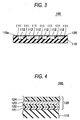
- Fig. 3 is a section view of a liquid supplying member according to a first embodiment of the invention;
- Fig. 4 is an enlarged section view of an elongated plate member of the liquid supplying member;
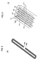
- Fig. 5 is a perspective view of the liquid supplying member;
- Fig. 6 is an enlarged perspective view showing one side of a base member of the liquid supplying member;
- Fig. 7 is an enlarged perspective view showing the other side of a base member of the liquid supplying member;
- Fig. 8 is a perspective view of one side of a connector showing a state that the liquid supplying member is connected;
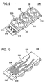
- Fig. 9 is a perspective view of the connector showing a state that the liquid supplying member is disconnected;
- Fig. 10 is a perspective view of the other side of the connector;
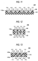
- Fig. 11 is a section view of a liquid supplying member according to a second embodiment of the invention;
- Fig. 12 is a section view of a liquid supplying member according to a third embodiment of the invention;
- Fig. 13 is a section view of a liquid supplying member according to a fourth embodiment of the invention;
- Figs. 14 and 15 are section views of a liquid supplying member according to a fifth embodiment of the invention;
- Fig. 16 is a side view showing the liquid supplying member of the fifth embodiment in a flexed state;
- Fig. 17 is a perspective view of a liquid supplying member according to a sixth embodiment of the invention;
- Fig. 18 is a section view taken along a line A-A of Fig. 17;
- Fig. 19 is a transverse section view of a liquid supplying member according to a seventh embodiment of the invention;
- Fig. 20 is a perspective view of a liquid supplying member according to an eighth embodiment of the invention;
- Fig. 21 is a side view of a liquid supplying member according to an ninth embodiment of the invention; and
- Fig. 22 is a side view of a liquid supplying member according to an tenth embodiment of the invention.
-
- Preferred embodiments of the invention will be described below in detail with reference to the accompanying drawings.
- As shown in Figs. 1 and 2, an ink
jet recording apparatus 10 is provided with: acarriage 42 which reciprocally travels so as to straddle a recorded object; arecording head 44 which is mounted on thecarriage 42 and subjects the object to recording, writing, or printing by ejecting a plurality of colors of ink to the object; a plurality ofcartridges 45 which contains different colors of ink therein; and aliquid supplying member 100. - The
carriage 42 is reciprocally moved along aguide shaft 48 by an unillustrated motor. Thecartridges 45 are fixed not to thecarriage 42 but to the main body of the inkjet recording apparatus 10. Theliquid supplying member 100 is made of plastic material (e.g., thermoplastic elastomer) and formed with a required number of channels (a plurality of channels in the embodiment) to supply a plurality of colors of ink held in therespective cartridges 45 to therecording head 44 that travels back and forth. Therecording head 44 ejects ink to theobject 11 located below a travel path of therecording head 44, to thus perform recording, writing, or printing operation. The plurality of colors of ink held in thecartridges 45 are supplied to one end 100a (see Fig. 5) of theliquid supplying member 100 by way of unillustrated stationary channels. - With such a configuration, it is possible to supply a plurality of colors of ink held in the plurality of
cartridges 45 to therecording head 44 by attaching only oneliquid supplying member 100 to the inkjet recording apparatus 10. Consequently, the inkjet recording apparatus 10 can be made compact. Further, the efforts required to mount theliquid supplying member 100 become smaller. - Here, in a case where an elastomer primarily made of SEPS (polystyrene-polyethylene-polypropylene-polystyrene) polymer is used as an elastic material to be used for forming the
liquid supplying member 100 is used, theliquid supplying member 100 becomes softer than the polyethylene tube. In this case, theliquid supplying member 100 can be folded largely, to thereby render the inkjet recording apparatus 10 particularly compact. Moreover, when thecarriage 42 is driven, the load exerted on a motor which drives thecarriage 42 becomes smaller. - The ink
jet recording apparatus 10 is an example of the liquid ejection apparatus. Further, therecording head 44 of the ink jet recording apparatus is an example of a liquid ejection head of the liquid ejection apparatus, and thecartridges 45 are examples of a liquid container. - However, the invention is not limited to these examples. Another example of the liquid ejection apparatus corresponds to a color filter manufacturing apparatus to be used for manufacturing a color filter of a liquid-crystal display. In this case, a coloring material ejection head of the apparatus is an example of the liquid ejection head. Another example of the liquid ejection apparatus is an electrode formation apparatus for forming electrodes, such as those of an organic EL display or those of a FED (Field Emission Display). In this case, an electrode material (a conductive paste) ejection head of the apparatus is an example of the liquid ejection head. Still another example of the liquid ejection apparatus is a biochip manufacturing apparatus for manufacturing a biochip. In this case, a bio-organic substance ejection head of the apparatus and a sample ejection head serving as a precision pipette correspond to examples of the liquid ejection head. The liquid ejection apparatus of the invention includes other industrial liquid ejection apparatuses of industrial application.
- The
object 11 is a substance to be subjected to recording, writing, or printing as a result of ejection of liquid. For instance, the object includes recording paper, a circuit board on which a circuit pattern such as electrodes of a display are printed, a CD-ROM on which a label is printed, and a preparation on which a DNA circuit is to be printed. - As shown in Fig. 3, the
liquid supplying member 100 according to a first invention comprises abase member 110 made of plastic material, and anelongated plate member 120 joined to oneface 110a of thebase member 110 by, e.g., adhesion or welding. While being joined to thebase member 110, theelongated plate member 120 has flexibility. - The
base member 110 is formed with a plurality ofelongated ridges 111 defining a plurality ofindividual grooves 112 each having rectangular cross section and arranged in a width direction of thebase member 110. Open side of thegrooves 112 are covered with theelongated plate member 112 to form a plurality of individual ink supplying channels. - Such a structure enables manufacture of the
liquid supplying member 100 by injecting plastic material (e.g., a thermoplastic elastomer) into a mold, to thereby mold thebase member 110. In this case, thebase member 110 can be formed into a complicated geometry, and manufacturing costs can be reduced. In addition to the SEPS polymer, the plastic material constituting theliquid supplying member 100 preferably includes paraffin oil serving as a softening agent. Further, the plastic material may contain polypropylene along with or separately from the paraffin oil. - Among the
ridges 111, ones provided at both widthwise ends of thebase member 110 are wider than the remainingridges 111. By such a configuration, the quantity of ink solvent (e.g., water) permeating through thebase member 110 and the quantity of outside air which permeates through thebase member 110 and dissolves in ink can be reduced. - As shown in Fig. 4, the
elongated plate member 120 has a multilayer structure in which awelding layer 121, areinforcement layer 122, ametal layer 123, and aprotective layer 124 are laminated, in the order given from thebase member 110. - The
welding layer 121 is for joining theelongated plate member 120 to thebase member 110 by welding. In a case where thebase member 110 includes the polypropylene as well as the SEPS, thewelding layer 121 is formed from polyethylene or polypropylene. - The
reinforcement layer 122 is for reinforcing theelongated plate member 120. Thereinforcement layer 122 also serves to improve the heat resistance of theelongated plate member 120. Specifically, thereinforcement layer 122 is formed from polyamide. - The
metal layer 123 is formed of an aluminum foil, for example. Providing themetal layer 123, theelongated plate member 120 serves to prevent evaporation of a solvent (water, for example) contained in ink. Themetal layer 123 also serves to prevent exterior air from penetrating through theelongated plate member 120 and dissolving in the ink. - The
protective layer 124 serves to protect themetal layer 123 physically and thermally, and is formed from, e.g., polyethylene terephthalate. Theprotective layer 124 also serves to reinforce theelongated plate member 120. - The
liquid supplying member 100 can be flexed in a direction orthogonal to theface 110a of thebase member 110 as shown in Fig. 8. Since thebase member 110 has elasticity higher than that of theelongated plate member 120, it is preferable to bent theliquid supplying member 100 such that thebase member 110 faces inwards. In this case, theelongated plate member 120 becomes less prone to being exfoliated from thebase member 110. Further, theelongated plate member 120 becomes less susceptible to slitting. - In a non-flexed state, as shown in Fig. 5, both ends 100a and 100b opposed to each other in the vicinity of the longitudinal center portion of the
liquid supplying member 100. Theliquid supplying member 100 is curved at an angle of 180° and at positions about a quarter of an entire longitudinal length from the both ends 100a and 100b. - With such a configuration, when the
base member 110 is subjected to the injection molding, the plastic material having flown through a single channel can be caused to simultaneously inject into areas in the mold corresponding to the both ends 100a, 100b, and the center section of thebase member 110. Accordingly, even when theliquid supplying member 100 is long, thebase member 110 can be formed through injection molding. - As shown in Fig. 6, each of the
grooves 112 formed in theface 110a extends up to a position before one end 100a of thebase member 110 and is connected to a throughhole 114 penetrating through to the other side face 110b opposite theface 110a. - As shown in Fig. 7, the through
holes 114 are arranged so as to become staggered with respect to the longitudinal direction of thebase member 110 so that the diameters of the throughholes 114 can be made larger than those achieved in a case where the throughholes 114 are arranged in parallel. - In the
other end 110b of theliquid supplying member 100 is configured so as to be identical with the end 100a. - As shown in Fig. 8, the
ink supplying member 100 is fastened to aconnector 200 by aretainer 300. Theconnector 200 is a member for readily connecting theliquid supplying member 100 to thecarriage 42 or therecording head 44. Theconnector 200 and theretainer 300 are formed from plastic material which is higher in rigidity than theliquid supplying member 100 at the room temperature. - As shown in Figs. 9 and 10, the
connector 200 is provided with: a plurality of cartridge-side connecting ports 210 respectively fitted with the throughholes 114; a plurality of head-side connecting ports 220 respectively fitted with thecarriage 42; andchannels 230 respectively communicating the cartridge-side connecting ports 210 and the head-side connecting ports 220. Theretainer 300 clamps theliquid supply member 100 in such a direction that the connectingports 210 are forced to be inserted into the throughholes 114. - The connecting
ports 210 are tubular members provided so as to stand upright on the main body of theconnector 200 and are arranged along one longitudinal end of theconnector 200 in a staggered manner. The arrangement of the connectingports 210 corresponds to the layout of the throughholes 114. - The connecting
ports 220 are tubular members standing upright on the main body of theconnector 200. A predetermined number of the connectingports 220 are provided at separated positions and are arranged in parallel with a short side of theconnector 200, thereby constituting groups. In the embodiment, each group comprises a pair of connectingports 220.Packings 222 are provided so as to surround the respective groups so that the chance of leakage of ink from the connection between the connectingports 220 and therecording head 44 can be prevented. Here, thepackings 222 may be omitted. - In the embodiment, the connecting
ports connector 200. However, they may be provided on different sides of the main body. - Another preferred embodiments of the invention will be described below. Members substantially identical with those described in the first embodiment are designated by the same reference numerals, and detailed explanation for those will be omitted.
- Fig. 11 shows a liquid supplying member according to a second embodiment of the invention. In this embodiment, each of
grooves 112 is configured so as to have a semicircular cross section, so that more smooth ink flows can be realized. - Fig. 12 shows a liquid supplying member according to a third embodiment of the invention. In this embodiment,
ridges 111 andgrooves 112 are provided in both offaces base member 110. Anelongated plate member 120 is joined to both thefaces grooves 112 per a unit area in theliquid supplying member 100 can be increased. - Fig. 13 shows a liquid supplying member according to a fourth embodiment of the invention. In this embodiment, each of
grooves 112 has a triangular cross section.Ridges 111 and thegrooves 112 are provided in bothfaces base member 110. Anelongated plate member 120 is caused to adhere to both theface grooves 112 formed in theface 110a and thegrooves 112 formed in theface 110b are arranged in a staggered manner with respect to the thickness direction of thebase member 110. By such an arrangement, the number of thegrooves 112 per a unit width in theliquid supplying member 100 can be increased, while the thickness of theliquid supplying member 100 can be reduced. - Fig. 14 shows a liquid supplying member according to a fifth embodiment of the invention. In this embodiment, at least a portion of a
base member 110 to be flexed is curved such that a face in whichgrooves 112 are formed faces outward. It may be curved such that the face in which thegrooves 112 are formed faces inward as shown in Fig. 15. With such a configuration, at portions B where theink supplying member 100 is flexed shown in Fig. 16, the portions B can be flexed more compactly. - Figs. 17 and 18 show a liquid supplying member according to a sixth embodiment of the invention. In this embodiment,
ridges 111 andgrooves 112 are provided in aface 110a of theliquid supplying member 100 within a range from one end 100a to an arbitrary intermediate point, while theridges 111 and thegrooves 112 are provided in anopposite face 110b within a range from the intermediate point to theother end 100b. Specifically, the ends of thegrooves 112 provided in theface 110a and the ends of thegrooves 112 provided in theface 110b are partly overlapped and communicated byconnection channels 116. - With such a structure, the through
holes 114 provided at the end 100a can be oriented in a direction different from that in which the throughholes 114 formed at theother end 100b are oriented. - Fig. 19 shows a liquid supplying member according to a seventh embodiment of the invention. In this embodiment, a cross-sectional area of each
groove 112 changes at a certain intermediate point in the longitudinal direction of abase member 110. In order to change the cross-sectional area of the groove, the width of thegroove 112 is changed at the intermediate point. However, the depth of thegroove 112 may be changed at the intermediate point. A portion of thegroove 112, which must be caused to pass through a narrow area in an inkjet recording apparatus 10, is given a small cross-sectional area, thereby making the cross section of theliquid supplying member 100 small. The other area of thegroove 112 is given a wider cross-sectional area. In this case, a pressure loss in ink due to flow of ink through thegroove 112 can be reduced. - Injection molding enables inexpensive manufacture of the
base member 110 of such a structure. - Fig. 20 shows a liquid supplying member according to an eighth embodiment of the invention. In this embodiment, a plurality of
projections 118 for fixing purpose are provided on side faces of abase member 110. Theprojections 118 are for fixing theliquid supplying member 100 within an inkjet recording apparatus 10. Adopting the injection molding to form thebase member 110, the positions and shape of the fixingprojections 118 can be set arbitrarily in consideration of the shape and position of an area where thebase member 110 is to be fixed. - Fig. 21 shows a liquid supplying member according to a ninth embodiment of the invention. In this embodiment, a portion of a
base member 110 which is not to be flexed is thicker than a portion of thebase member 110 which is to be flexed. With such a configuration, the solvent of ink becomes less prone to passing through thebase member 110 and evaporating. Further, theliquid supplying member 100 remains easily foldable. In the modification, aface 110a in whichgrooves 112 are formed is made flush, and irregularities are formed in anopposite face 110b, thereby changing the thickness of thebase member 110. - Fig. 22 shows a liquid supplying member according to a tenth embodiment of the invention. In this embodiment, each of a
face 110a and aface 110b are provided with anelongated plate member 120 at a portion of abase member 110 which is not to be flexed, while only theface 110a is provided with theelongated plate member 120 at a portion of thebase member 110 which is to be flexed. - With such a configuration, even if the solvent of ink has permeated through the
base member 110, the solvent will be blocked by theelongated plate member 120, thereby rendering the ink less prone to evaporating. Since theelongated plate member 120 is joined to only theface 110a in the portion where theliquid supplying member 100 to be flexed, the flexibility of theliquid supplying member 100 is not impaired. - Although the present invention has been shown and described with reference to specific preferred embodiments, various changes and modifications will be apparent to those skilled in the art from the teachings herein. Such changes and modifications as are obvious are deemed to come within the spirit, scope and contemplation of the invention as defined in the appended claims.
Claims (19)
- A liquid supplying member, for supplying liquid from a liquid container to a liquid ejection head provided in a liquid ejection apparatus, the liquid supplying member comprising:a flexible base member, having a first face in which a plurality of first grooves are arranged side by side in a first direction; anda first flexible plate member, joined to the first face of the base member so as to seal the first grooves to form liquid supplying channels.
- The liquid supplying member as set forth in claim 1, wherein each of the first grooves is formed with a through hole extending to a second face of the base member which is opposite to the first face.
- The liquid supplying member as set forth in claim 1 or 2, wherein the base member is comprised of a thermoplastic elastomer.
- The liquid supplying member as set forth in claim 3, wherein:the thermoplastic elastomer is comprised of polypropylene; andthe first plate member comprises a first layer which is joined to the first face of the base member and comprised of at least one of polypropylene and polyethylene.
- The liquid supplying member as set forth in any of claims 1 to 4, wherein the first plate member comprises a second layer comprised of metal.
- The liquid supplying member as set forth in claim 5, wherein the first plate member comprises a third layer comprised of polyamide and a fourth layer comprised of polyethylene terephthalate, between which the second layer is sandwiched.
- The liquid supplying member as set forth in any of claims 2 to 6, further comprising a second flexible plate member which is joined to a part of the second face and comprised of a metal layer.
- The liquid supplying member as set forth in any of claims 1 to 7, wherein:the liquid supplying member comprises a first portion to be flexed and a second portion not to be flexed; andthe first portion has a first thickness and the second portion has a second thickness thicker than the first thickness.
- The liquid supplying member as set forth in any of claims 1 to 8, wherein:the liquid supplying member comprises a first portion to be flexed and a second portion not to be flexed; anda portion of the base member corresponding to at least the first portion has a cross section curved in a direction that the liquid supplying member is to be flexed.
- The liquid supplying member as set forth in any of claims 2 to 9, wherein:the second face of the base member is formed with a plurality of second grooves arranged side by side in the first direction and sealed by a second flexible plate member.
- The liquid supplying member as set forth in claim 10, wherein each one of the first grooves is communicated with associated one of the second grooves.
- The liquid supplying member as set forth in claim 10 or 11, wherein each of the second grooves is formed with a through hole extending to the first face.
- The liquid supplying member as set forth in any of claims 1 to 12, further comprising a connector having a higher rigidity than the base member and communicating the first grooves and the liquid ejection head.
- The liquid supplying member as set forth in any of claims 1 to 13, wherein a cross-sectional area of each of the first grooves is partly changed.
- The liquid supplying member as set forth in any of claims 1 to 14, wherein the base member is curved such that both longitudinal ends are opposed to each other in the vicinity of a longitudinal center portion thereof, in an original state.
- A method of manufacturing a liquid supplying member for supplying liquid from a liquid container to a liquid ejection head provided in a liquid ejection apparatus, the method comprising steps of:providing a mold for forming a base member having a first face in which a plurality of first grooves are arranged side by side in a first direction;injecting molten thermoplastic elastomer into the mold to form the base member having a flexibility; andjoining a flexible plate member to the first face of the base member so as to seal the first grooves to form liquid supplying channels.
- The manufacturing method as set forth in claim 16, wherein:the mold is configured such that the base member is curved such that both longitudinal ends are opposed to each other in the vicinity of a longitudinal center portion thereof; andthe thermoplastic elastomer is injected from portions of the mold corresponding to the both longitudinal ends and the longitudinal center portion.
- A liquid ejection apparatus in which the liquid supplying member as set forth in any of claims 1 to 15 is extended from the liquid container to the liquid ejection head.
- The liquid ejection apparatus as set forth in claim 18, wherein the liquid supplying member is flexed such that either one of the base member or the first plate member having a higher elasticity than the other faces inwards.
Applications Claiming Priority (4)
| Application Number | Priority Date | Filing Date | Title |
|---|---|---|---|
| JP2003026154A JP3573151B2 (en) | 2002-02-28 | 2003-02-03 | Liquid supply tube for liquid ejecting apparatus and liquid ejecting apparatus |
| JP2003026154 | 2003-02-03 | ||
| JP2003120528 | 2003-04-24 | ||
| JP2003120528A JP3979336B2 (en) | 2003-04-24 | 2003-04-24 | Liquid conducting material, method for manufacturing the same, and liquid ejecting apparatus |
Publications (2)
| Publication Number | Publication Date |
|---|---|
| EP1442890A1 true EP1442890A1 (en) | 2004-08-04 |
| EP1442890B1 EP1442890B1 (en) | 2006-06-14 |
Family
ID=32658621
Family Applications (1)
| Application Number | Title | Priority Date | Filing Date |
|---|---|---|---|
| EP03018761A Expired - Lifetime EP1442890B1 (en) | 2003-02-03 | 2003-08-27 | Liquid supplying member, method of manufacturing the same, and liquid ejection apparatus incorporating the same |
Country Status (4)
| Country | Link |
|---|---|
| EP (1) | EP1442890B1 (en) |
| CN (1) | CN1292908C (en) |
| AT (1) | ATE329763T1 (en) |
| DE (1) | DE60306095T2 (en) |
Cited By (1)
| Publication number | Priority date | Publication date | Assignee | Title |
|---|---|---|---|---|
| JP2012148470A (en) * | 2011-01-19 | 2012-08-09 | Seiko Epson Corp | Flow path component and image forming apparatus including the same |
Families Citing this family (2)
| Publication number | Priority date | Publication date | Assignee | Title |
|---|---|---|---|---|
| JP4122522B2 (en) * | 2005-01-27 | 2008-07-23 | セイコーエプソン株式会社 | LIQUID CONTAINING CONTAINER, LIQUID DISCHARGE HEAD HAVING THE SAME, LIQUID DISCHARGE DEVICE, AND METHOD OF SUPPLYING LIQUID AND LIQUID DISCHARGE METHOD |
| JP2009023235A (en) * | 2007-07-20 | 2009-02-05 | Seiko Epson Corp | Fluid ejection device |
Citations (5)
| Publication number | Priority date | Publication date | Assignee | Title |
|---|---|---|---|---|
| JPS57210879A (en) * | 1981-06-23 | 1982-12-24 | Nippon Telegr & Teleph Corp <Ntt> | Ink feeding and collecting pipe and manufacture thereof |
| JPS6154941A (en) * | 1984-08-28 | 1986-03-19 | Canon Inc | Ink feed pipe and ink jet recorder having said ink feed pipe |
| US5025270A (en) * | 1988-06-27 | 1991-06-18 | Seiko Instruments, Inc. | Recording apparatus coupled ink supply tubes |
| US5043746A (en) * | 1984-05-04 | 1991-08-27 | Canon Kabushiki Kaisha | Liquid jet pipe holding element |
| EP1172218A1 (en) * | 2000-05-15 | 2002-01-16 | Hewlett Packard Company, a Delaware Corporation | One piece tubes guide |
Family Cites Families (3)
| Publication number | Priority date | Publication date | Assignee | Title |
|---|---|---|---|---|
| JPH0446U (en) * | 1990-04-13 | 1992-01-06 | ||
| JP3236389B2 (en) * | 1993-01-05 | 2001-12-10 | 株式会社リコー | Ink jet recording device |
| JP2001026119A (en) * | 1999-07-13 | 2001-01-30 | Canon Inc | Ink jet recording device |
-
2003
- 2003-08-26 CN CNB03156402XA patent/CN1292908C/en not_active Expired - Fee Related
- 2003-08-27 EP EP03018761A patent/EP1442890B1/en not_active Expired - Lifetime
- 2003-08-27 DE DE60306095T patent/DE60306095T2/en not_active Expired - Lifetime
- 2003-08-27 AT AT03018761T patent/ATE329763T1/en not_active IP Right Cessation
Patent Citations (5)
| Publication number | Priority date | Publication date | Assignee | Title |
|---|---|---|---|---|
| JPS57210879A (en) * | 1981-06-23 | 1982-12-24 | Nippon Telegr & Teleph Corp <Ntt> | Ink feeding and collecting pipe and manufacture thereof |
| US5043746A (en) * | 1984-05-04 | 1991-08-27 | Canon Kabushiki Kaisha | Liquid jet pipe holding element |
| JPS6154941A (en) * | 1984-08-28 | 1986-03-19 | Canon Inc | Ink feed pipe and ink jet recorder having said ink feed pipe |
| US5025270A (en) * | 1988-06-27 | 1991-06-18 | Seiko Instruments, Inc. | Recording apparatus coupled ink supply tubes |
| EP1172218A1 (en) * | 2000-05-15 | 2002-01-16 | Hewlett Packard Company, a Delaware Corporation | One piece tubes guide |
Non-Patent Citations (2)
| Title |
|---|
| PATENT ABSTRACTS OF JAPAN vol. 007, no. 068 (M - 201) 19 March 1983 (1983-03-19) * |
| PATENT ABSTRACTS OF JAPAN vol. 010, no. 216 (M - 502) 29 July 1986 (1986-07-29) * |
Cited By (1)
| Publication number | Priority date | Publication date | Assignee | Title |
|---|---|---|---|---|
| JP2012148470A (en) * | 2011-01-19 | 2012-08-09 | Seiko Epson Corp | Flow path component and image forming apparatus including the same |
Also Published As
| Publication number | Publication date |
|---|---|
| DE60306095D1 (en) | 2006-07-27 |
| DE60306095T2 (en) | 2006-12-28 |
| CN1292908C (en) | 2007-01-03 |
| EP1442890B1 (en) | 2006-06-14 |
| ATE329763T1 (en) | 2006-07-15 |
| CN1519125A (en) | 2004-08-11 |
Similar Documents
| Publication | Publication Date | Title |
|---|---|---|
| US12214600B2 (en) | Liquid discharging head, liquid discharging unit, and device for discharging liquid | |
| US7370949B2 (en) | Liquid supplying member, method of manufacturing the same, and liquid ejection apparatus incorporating the same | |
| JP3573151B2 (en) | Liquid supply tube for liquid ejecting apparatus and liquid ejecting apparatus | |
| US7331652B2 (en) | Joint structure and method of producing same | |
| US7413296B2 (en) | Liquid supplying member, method of manufacturing the same, and liquid ejection apparatus incorporating the same | |
| US7201475B2 (en) | Liquid supplying member, method of manufacturing the same, and liquid ejection apparatus incorporating the same | |
| EP1442890B1 (en) | Liquid supplying member, method of manufacturing the same, and liquid ejection apparatus incorporating the same | |
| CN110893727A (en) | liquid ejection head | |
| JP2011056872A (en) | Sealing member, liquid jetting head and liquid jetting device | |
| JP4810861B2 (en) | Liquid supply member and liquid ejecting apparatus | |
| JP3979336B2 (en) | Liquid conducting material, method for manufacturing the same, and liquid ejecting apparatus | |
| US7419251B2 (en) | Overmolded tube header | |
| US20070242116A1 (en) | Liquid seal and liquid ejection apparatus | |
| JP4470404B2 (en) | Liquid conducting material and liquid ejecting apparatus | |
| JP4052176B2 (en) | Liquid conducting material, method for manufacturing the same, and liquid ejecting apparatus | |
| JP4305076B2 (en) | Liquid conducting material and liquid ejecting apparatus | |
| JP4453725B2 (en) | Liquid sealing member and liquid conducting material | |
| US7399003B2 (en) | Duct connecting structure | |
| CN1695950B (en) | Liquid supply member and liquid ejecting apparatus | |
| CN2736167Y (en) | Liquid feeding component and liquid injection apparatus comprising the same | |
| JP4277600B2 (en) | Liquid supply device and liquid ejection device | |
| JP4360137B2 (en) | Liquid conducting material and liquid ejecting apparatus | |
| JP4341319B2 (en) | Liquid supply device and liquid ejection device | |
| JP2005081638A (en) | Liquid conducting material, liquid ejecting apparatus, and liquid conducting material inspection method | |
| JP2009262564A (en) | Liquid-conducting material, liquid-jetting device, and method for manufacturing liquid-conducting material |
Legal Events
| Date | Code | Title | Description |
|---|---|---|---|
| PUAI | Public reference made under article 153(3) epc to a published international application that has entered the european phase |
Free format text: ORIGINAL CODE: 0009012 |
|
| AK | Designated contracting states |
Kind code of ref document: A1 Designated state(s): AT BE BG CH CY CZ DE DK EE ES FI FR GB GR HU IE IT LI LU MC NL PT RO SE SI SK TR |
|
| AX | Request for extension of the european patent |
Extension state: AL LT LV MK |
|
| 17P | Request for examination filed |
Effective date: 20040722 |
|
| AKX | Designation fees paid |
Designated state(s): AT BE BG CH CY CZ DE DK EE ES FI FR GB GR HU IE IT LI LU MC NL PT RO SE SI SK TR |
|
| GRAP | Despatch of communication of intention to grant a patent |
Free format text: ORIGINAL CODE: EPIDOSNIGR1 |
|
| GRAS | Grant fee paid |
Free format text: ORIGINAL CODE: EPIDOSNIGR3 |
|
| GRAA | (expected) grant |
Free format text: ORIGINAL CODE: 0009210 |
|
| AK | Designated contracting states |
Kind code of ref document: B1 Designated state(s): AT BE BG CH CY CZ DE DK EE ES FI FR GB GR HU IE IT LI LU MC NL PT RO SE SI SK TR |
|
| PG25 | Lapsed in a contracting state [announced via postgrant information from national office to epo] |
Ref country code: SI Free format text: LAPSE BECAUSE OF FAILURE TO SUBMIT A TRANSLATION OF THE DESCRIPTION OR TO PAY THE FEE WITHIN THE PRESCRIBED TIME-LIMIT Effective date: 20060614 Ref country code: NL Free format text: LAPSE BECAUSE OF FAILURE TO SUBMIT A TRANSLATION OF THE DESCRIPTION OR TO PAY THE FEE WITHIN THE PRESCRIBED TIME-LIMIT Effective date: 20060614 Ref country code: CZ Free format text: LAPSE BECAUSE OF FAILURE TO SUBMIT A TRANSLATION OF THE DESCRIPTION OR TO PAY THE FEE WITHIN THE PRESCRIBED TIME-LIMIT Effective date: 20060614 Ref country code: IT Free format text: LAPSE BECAUSE OF FAILURE TO SUBMIT A TRANSLATION OF THE DESCRIPTION OR TO PAY THE FEE WITHIN THE PRESCRIBED TIME-LIMIT;WARNING: LAPSES OF ITALIAN PATENTS WITH EFFECTIVE DATE BEFORE 2007 MAY HAVE OCCURRED AT ANY TIME BEFORE 2007. THE CORRECT EFFECTIVE DATE MAY BE DIFFERENT FROM THE ONE RECORDED. Effective date: 20060614 Ref country code: AT Free format text: LAPSE BECAUSE OF FAILURE TO SUBMIT A TRANSLATION OF THE DESCRIPTION OR TO PAY THE FEE WITHIN THE PRESCRIBED TIME-LIMIT Effective date: 20060614 Ref country code: BE Free format text: LAPSE BECAUSE OF FAILURE TO SUBMIT A TRANSLATION OF THE DESCRIPTION OR TO PAY THE FEE WITHIN THE PRESCRIBED TIME-LIMIT Effective date: 20060614 Ref country code: CH Free format text: LAPSE BECAUSE OF FAILURE TO SUBMIT A TRANSLATION OF THE DESCRIPTION OR TO PAY THE FEE WITHIN THE PRESCRIBED TIME-LIMIT Effective date: 20060614 Ref country code: SK Free format text: LAPSE BECAUSE OF FAILURE TO SUBMIT A TRANSLATION OF THE DESCRIPTION OR TO PAY THE FEE WITHIN THE PRESCRIBED TIME-LIMIT Effective date: 20060614 Ref country code: FI Free format text: LAPSE BECAUSE OF FAILURE TO SUBMIT A TRANSLATION OF THE DESCRIPTION OR TO PAY THE FEE WITHIN THE PRESCRIBED TIME-LIMIT Effective date: 20060614 Ref country code: LI Free format text: LAPSE BECAUSE OF FAILURE TO SUBMIT A TRANSLATION OF THE DESCRIPTION OR TO PAY THE FEE WITHIN THE PRESCRIBED TIME-LIMIT Effective date: 20060614 Ref country code: RO Free format text: LAPSE BECAUSE OF FAILURE TO SUBMIT A TRANSLATION OF THE DESCRIPTION OR TO PAY THE FEE WITHIN THE PRESCRIBED TIME-LIMIT Effective date: 20060614 |
|
| REG | Reference to a national code |
Ref country code: GB Ref legal event code: FG4D |
|
| REG | Reference to a national code |
Ref country code: CH Ref legal event code: EP |
|
| REG | Reference to a national code |
Ref country code: IE Ref legal event code: FG4D |
|
| REF | Corresponds to: |
Ref document number: 60306095 Country of ref document: DE Date of ref document: 20060727 Kind code of ref document: P |
|
| PG25 | Lapsed in a contracting state [announced via postgrant information from national office to epo] |
Ref country code: IE Free format text: LAPSE BECAUSE OF NON-PAYMENT OF DUE FEES Effective date: 20060828 |
|
| PG25 | Lapsed in a contracting state [announced via postgrant information from national office to epo] |
Ref country code: MC Free format text: LAPSE BECAUSE OF NON-PAYMENT OF DUE FEES Effective date: 20060831 |
|
| PG25 | Lapsed in a contracting state [announced via postgrant information from national office to epo] |
Ref country code: SE Free format text: LAPSE BECAUSE OF FAILURE TO SUBMIT A TRANSLATION OF THE DESCRIPTION OR TO PAY THE FEE WITHIN THE PRESCRIBED TIME-LIMIT Effective date: 20060914 Ref country code: DK Free format text: LAPSE BECAUSE OF FAILURE TO SUBMIT A TRANSLATION OF THE DESCRIPTION OR TO PAY THE FEE WITHIN THE PRESCRIBED TIME-LIMIT Effective date: 20060914 |
|
| PG25 | Lapsed in a contracting state [announced via postgrant information from national office to epo] |
Ref country code: ES Free format text: LAPSE BECAUSE OF FAILURE TO SUBMIT A TRANSLATION OF THE DESCRIPTION OR TO PAY THE FEE WITHIN THE PRESCRIBED TIME-LIMIT Effective date: 20060925 |
|
| PG25 | Lapsed in a contracting state [announced via postgrant information from national office to epo] |
Ref country code: PT Free format text: LAPSE BECAUSE OF FAILURE TO SUBMIT A TRANSLATION OF THE DESCRIPTION OR TO PAY THE FEE WITHIN THE PRESCRIBED TIME-LIMIT Effective date: 20061114 |
|
| NLV1 | Nl: lapsed or annulled due to failure to fulfill the requirements of art. 29p and 29m of the patents act | ||
| REG | Reference to a national code |
Ref country code: CH Ref legal event code: PL |
|
| ET | Fr: translation filed | ||
| PLBE | No opposition filed within time limit |
Free format text: ORIGINAL CODE: 0009261 |
|
| STAA | Information on the status of an ep patent application or granted ep patent |
Free format text: STATUS: NO OPPOSITION FILED WITHIN TIME LIMIT |
|
| 26N | No opposition filed |
Effective date: 20070315 |
|
| PG25 | Lapsed in a contracting state [announced via postgrant information from national office to epo] |
Ref country code: GR Free format text: LAPSE BECAUSE OF FAILURE TO SUBMIT A TRANSLATION OF THE DESCRIPTION OR TO PAY THE FEE WITHIN THE PRESCRIBED TIME-LIMIT Effective date: 20060915 |
|
| PG25 | Lapsed in a contracting state [announced via postgrant information from national office to epo] |
Ref country code: EE Free format text: LAPSE BECAUSE OF FAILURE TO SUBMIT A TRANSLATION OF THE DESCRIPTION OR TO PAY THE FEE WITHIN THE PRESCRIBED TIME-LIMIT Effective date: 20060614 Ref country code: BG Free format text: LAPSE BECAUSE OF FAILURE TO SUBMIT A TRANSLATION OF THE DESCRIPTION OR TO PAY THE FEE WITHIN THE PRESCRIBED TIME-LIMIT Effective date: 20060914 |
|
| PG25 | Lapsed in a contracting state [announced via postgrant information from national office to epo] |
Ref country code: HU Free format text: LAPSE BECAUSE OF FAILURE TO SUBMIT A TRANSLATION OF THE DESCRIPTION OR TO PAY THE FEE WITHIN THE PRESCRIBED TIME-LIMIT Effective date: 20061215 Ref country code: TR Free format text: LAPSE BECAUSE OF FAILURE TO SUBMIT A TRANSLATION OF THE DESCRIPTION OR TO PAY THE FEE WITHIN THE PRESCRIBED TIME-LIMIT Effective date: 20060614 Ref country code: LU Free format text: LAPSE BECAUSE OF NON-PAYMENT OF DUE FEES Effective date: 20060827 |
|
| PG25 | Lapsed in a contracting state [announced via postgrant information from national office to epo] |
Ref country code: CY Free format text: LAPSE BECAUSE OF FAILURE TO SUBMIT A TRANSLATION OF THE DESCRIPTION OR TO PAY THE FEE WITHIN THE PRESCRIBED TIME-LIMIT Effective date: 20060614 |
|
| REG | Reference to a national code |
Ref country code: FR Ref legal event code: PLFP Year of fee payment: 14 |
|
| REG | Reference to a national code |
Ref country code: FR Ref legal event code: PLFP Year of fee payment: 15 |
|
| REG | Reference to a national code |
Ref country code: FR Ref legal event code: PLFP Year of fee payment: 16 |
|
| PGFP | Annual fee paid to national office [announced via postgrant information from national office to epo] |
Ref country code: DE Payment date: 20180814 Year of fee payment: 16 Ref country code: FR Payment date: 20180712 Year of fee payment: 16 |
|
| PGFP | Annual fee paid to national office [announced via postgrant information from national office to epo] |
Ref country code: GB Payment date: 20180822 Year of fee payment: 16 |
|
| REG | Reference to a national code |
Ref country code: DE Ref legal event code: R119 Ref document number: 60306095 Country of ref document: DE |
|
| GBPC | Gb: european patent ceased through non-payment of renewal fee |
Effective date: 20190827 |
|
| PG25 | Lapsed in a contracting state [announced via postgrant information from national office to epo] |
Ref country code: FR Free format text: LAPSE BECAUSE OF NON-PAYMENT OF DUE FEES Effective date: 20190831 Ref country code: DE Free format text: LAPSE BECAUSE OF NON-PAYMENT OF DUE FEES Effective date: 20200303 |
|
| PG25 | Lapsed in a contracting state [announced via postgrant information from national office to epo] |
Ref country code: GB Free format text: LAPSE BECAUSE OF NON-PAYMENT OF DUE FEES Effective date: 20190827 |