EP1442838A2 - Honing method and honing apparatus - Google Patents
Honing method and honing apparatus Download PDFInfo
- Publication number
- EP1442838A2 EP1442838A2 EP03018334A EP03018334A EP1442838A2 EP 1442838 A2 EP1442838 A2 EP 1442838A2 EP 03018334 A EP03018334 A EP 03018334A EP 03018334 A EP03018334 A EP 03018334A EP 1442838 A2 EP1442838 A2 EP 1442838A2
- Authority
- EP
- European Patent Office
- Prior art keywords
- honing
- coarse
- finishing
- section
- head
- Prior art date
- Legal status (The legal status is an assumption and is not a legal conclusion. Google has not performed a legal analysis and makes no representation as to the accuracy of the status listed.)
- Granted
Links
Images


Classifications
-
- B—PERFORMING OPERATIONS; TRANSPORTING
- B24—GRINDING; POLISHING
- B24B—MACHINES, DEVICES, OR PROCESSES FOR GRINDING OR POLISHING; DRESSING OR CONDITIONING OF ABRADING SURFACES; FEEDING OF GRINDING, POLISHING, OR LAPPING AGENTS
- B24B33/00—Honing machines or devices; Accessories therefor
- B24B33/02—Honing machines or devices; Accessories therefor designed for working internal surfaces of revolution, e.g. of cylindrical or conical shapes
Definitions
- the present invention relates to a honing method and a honing apparatus for grinding the inner surface of a workpiece carried on a machining line by rotating a honing head having hones relative to the workpiece while axially moving the honing head.
- a workpiece having a cylindrical inner surface, e.g., the cylinder bore of a cylinder block is an important region that determines engine performance. For this reason, the cylinder bore is required to have high shape accuracy and good surface profile. As the shape accuracy, it is required to make the roundness and cylindricity of the cylinder bore as high as possible in order to reduce piston sliding resistance. As for the surface profile, it is desirable to ensure enough roughness to hold oil and expose graphite, serving as a fixed lubricant, to the surface of the bore as much as possible in order to decrease the seizure (scuff) of the piston.
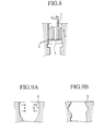
- a honing head 5 having hones 3 is inserted into the inner peripheral surface of the cylinder bore 1, rotated and axially moved to conduct grinding, thereby executing the honing of the cylinder bore 1 as shown in Fig. 8 (refer to Japanese Patent Application Laid-Open Publications No. 5-57597 and No. 5-57598).
- the honing head 5 has a plurality of hones 3 in a circumferential direction and the honing head 5 hones the inner peripheral surface of the cylinder bore 1 while pressing the hones 3 radially outward, i.e., toward the bore inner peripheral surface of the cylinder bore 1 with a predetermined expansion pressure.
- Fig. 9A shows the deformation state of the cylinder bore 1 during the coarse honing. According to Fig. 9A, the cylinder bore 1 is deformed so as to largely widen the upper opening side of the cylinder bore 1 radially outward and to decrease the inside diameter of the lower portion of the cylinder bore 1.
- an object of the present invention to allow the shape of a workpiece to be secured highly accurately in finishing honing without bringing about the extension of machining time.
- a first aspect of the present invention provides a honing method for grinding an inner surface of a cylinder of a workpiece that is carried on a machining line by rotating a honing head having hones while axially moving the honing head, characterized in that in a coarse honing step, coarse honing is conducted to the inner surface of the cylinder, in an idling step, the workpiece is left as it is for a predetermined time without inserting the honing head into the cylinder, and in a subsequent finishing honing step, the honing head is rotated in a reverse direction to a rotational direction in the coarse honing step, thereby conducting honing to inner surface of the cylinder of the workpiece.
- a second aspect of the present invention provides the honing method according to the first aspect, wherein a coolant is supplied to the workpiece in the idling step.
- a third aspect of the present invention provides the honing method according to the second aspect, wherein the coolant is set equal in temperature to coolants used in the coarse honing step and the finishing honing step.
- a fourth aspect of the present invention provides the honing method according to any of the first to the third aspect, wherein a time for which the workpiece is left as it is in the idling step is at least 30 seconds. If the workpiece leaving time is less than 30 seconds, a return deformation quantity by the springback function after the coarse honing step is insufficient as shown in Fig. 3, with the result that the subsequent finishing honing step is influenced by the springback.
- a fifth aspect of the present invention provides a honing apparatus for grinding an inner surface of a cylinder of a workpiece that is carried on a machining line by rotating a honing head having hones while axially moving the honing head, the honing apparatus comprising: a section of a coarse honing step and a section of a finishing honing step provided on the machining line; and a section of an idling step for leaving the workpiece, which has been subjected to the coarse honing step, as it is for a predetermined time without inserting the honing head into the cylinder, the idling step section provided between the coarse honing step section and the finishing honing step section, characterized in that a rotational direction of the honing head in the finishing honing step is reverse to a rotational direction of the honing head in the coarse honing step.
- the idling step for leaving the workpiece as it is for a predetermined time is provided between the coarse honing step and the finishing honing step on the same line. Therefore, the workpiece is deformed by springback during this idling step, it is possible to eliminate the influence of the springback in the following finishing honing step, and it is possible to highly accurately secure the shape of the workpiece.
- this idling step is set on the same line as that of the coarse honing step and the finishing honing step and provided therebetween, it is unnecessary to separately provide a dedicated space for leaving the workpiece as it is, excessive time is not generated and the extension of machining time is thereby avoided.
- the honing head is rotated in a reverse direction to the rotational direction in the coarse honing. Due to this, plastic flow on the honing target surface of the workpiece generated in the finishing honing is generated in a reverse direction to the direction of plastic flow generated in the coarse honing and the plastic flow in the finishing honing functions to cancel the plastic flow in the coarse honing. As a result, it is possible to decrease the plastic flow in the finishing honing, suppress the occurrence of microscopic burrs, and thereby obtain a highly accurately honed surface.
- the temperature change of the workpiece becomes uniform as a whole and a springback quantity becomes uniform on the honing target surface as a whole. Therefore, it is possible to prevent machining allowance from becoming unnecessarily large in the finishing honing and shorten finishing honing time.
- the coolant supplied in the idling step is set equal in temperature to the coolant used in the coarse honing step and the finishing honing step.
- the fourth aspect of the invention by setting the time for leaving the workpiece as it is in the idling step to at least 30 seconds, a return deformation quantity by the springback function after the coarse honing is sufficiently obtained and it is possible to eliminate the influence of the springback in the subsequent finishing honing.
- Fig. 1 shows a honing method in one embodiment according to the present invention.
- reference symbol 101 denotes a coarse honing step section for the honing method
- 103 denotes a finishing honing step section therefore.
- an idling step section 102 for leaving a workpiece as it is for a predetermined time (“left-alone time” or "leaving time"
- step sections are set on the same machining line (working line).
- An engine cylinder block 11 having a cylindrical inner surface is carried on this line as a workpiece in the order of the coarse honing step section 101, the idling step section 102 and the finishing honing step section 103.
- a honing head 15 is inserted into the cylinder bore 13 of the cylinder block 11.
- a plurality of rectangular parallelepiped coarse honing hones 17 long in a longitudinal direction in Fig. 1 are provided on the outer peripheral portion of the honing head equidistantly in a circumferential direction.
- These coarse honing hones 17 can be pressed against the inner peripheral surface of the cylinder bore 13 with a predetermined expansion pressure T 1 by an expansion pressure mechanism which is not shown.
- the honing head 15 provided with such coarse honing hones 17 conducts coarse honing to the inner peripheral surface of the cylinder bore 13 by rotating axially, i.e., longitudinally in Fig. 1, while moving.
- the cylinder bore 13 of the cylinder block 11 is finished using a honing head 21 provided with finishing honing hones 19.
- a plurality of rectangular parallelepiped finishing honing hones 19 long in the longitudinal direction in Fig. 1 are provided equidistantly in the circumferential direction, and the finishing honing hones 19 can be pressed against the inner peripheral surface of the cylinder bore 13 with a predetermined expansion pressure T 2 by an expansion pressure mechanism which is not shown.
- the honing head 21 provided with these finishing honing hones 19 rotates while axially moving similarly to the honing head 15 for the coarse honing. However, the rotational direction of the honing head 21 is reverse to that during the coarse honing.
- coolant nozzles 23, 25 and 27 for supplying a coolant as a cooling liquid into the cylinder bore 13 are disposed, respectively.
- the coolant is supplied to the respective coolant nozzles 23, 25 and 27 from a common coolant supply source 29 through a piping 31.
- the cylinder block 11 having the cylinder bore 13 subjected to the coarse honing in the step of coarse honing step section 101 is carried to the next idling step section 102, where the cylinder block 11 is left as it is for a 60 seconds of predetermined time. While the cylinder block 11 is left as it is, the other cylinder blocks are subjected to coarse honing and finishing honing in the coarse honing step section 101 and the finishing honing step section 103 provided before and after the idling step section 102, respectively.
- the time for which the cylinder block 11 is left in the idling step section 102 may be at least 30 seconds.
- the cylinder bore 13 is deformed similarly to Fig. 9A by the expansion pressure T 1 applied from the coarse honing hones 17 as indicated by a two-dot chain line in the idling step section 102 in Fig. 1.
- T 1 applied from the coarse honing hones 17 as indicated by a two-dot chain line in the idling step section 102 in Fig. 1.
- the cylinder bore 13 is contractedly deformed by the function of springback S as indicated by a solid line in the idling step section 102 in Fig. 1.
- a springback quantity (springback degree) becomes nearly a maximum.
- the cylinder bore 13 in the state of the maximum springback quantity has concave portions 13a, 13b and the like almost equal to one another in inside diameter in the axial direction and convex portions 13c, 13d, 13e and the like adjacent the respective concave portions and almost equal to one another in inside diameter.
- the cylinder block 11 left as it is for 60 seconds after the coarse honing is carried to the next finishing honing step section 103, where the cylinder block 11 is subjected to finishing honing by rotating the honing head 21 provided with the finishing honing hones 19 in a direction reverse to the direction in the coarse honing section 101.
- the expansion pressure T 1 is made several times as high as the expansion pressure T 2 during the finishing honing so as to hone much machining allowance (working allowance ) in short time. Due to this, the springback of the cylinder block 11 right after the coarse honing is quite large in quantity and it takes about 60 seconds until the return deformation caused by this springback becomes nearly a maximum.
- the setting of this idling step section 102 has the following two advantages.
- the cylinder bore 13 is forcedly widened by the coarse honing hones 17 as indicated by the two-dot chain line in the idling step section 102 in Fig. 1.
- the concave portions 13a, 13b and the like and the convex portions 13c, 13d, 13e and the like are generated as indicated by the solid line in the idling step section 102 in Fig. 1.
- each of the finishing honing hones 19 is pressed against the honing target surface with a fixed force F, so that the surface pressure of the regions of the finishing honing hone 19 that are locally abutted against the honing target surface increases.
- Honing is featured in that as the surface pressure increases, the quantity of the abrasive grains of the hone cut into the honing target surface increases and grinding efficiency increases. Therefore, honing time for honing the honing target surface having irregularities is shorter than honing time for honing the honing target surface having no irregularities (the full abutment of the hone against the honing target surface).
- the protrusion quantity h (see Fig. 3) of each of the convex portions 13c, 13d, 13e and the like relative to each of the concave portions 13a and 13b on the honing target surface is about 30 to 50 % of the machining allowance for the finishing honing.
- the machining time (working time) is advantageously about 10 % shorter than the conventional machining time during the finishing honing.
- a direction indicated by an arrow X is the moving direction of the finishing honing hone 19
- reference symbol 37 denotes plastic flow generated in the coarse honing step section 101 and 39 denotes resistance force (load) caused by this plastic flow 37.
- the shape accuracy (roundness, cylindricity) of the cylinder bore 13 using a honing method C in which the idling step section 102 is provided improves about 30 % from that using a conventional honing method A.
- the exposure degree of graphite to the inner peripheral surface of the cylinder bore 13 using the honing method C in which the idling step section 102 is provided improves about 40 % from that using the conventional honing method A.
- the exposure degree of graphite increases because of the reduction of plastic flow, as will be described later.
- the expansion pressure T 1 of the coarse honing hones 17 is high and the abrasive grains of the coarse honing hones 17 larger in grain size than the abrasive grains of the finishing honing hones 19 are used in order to improve grinding efficiency. Due to this, as shown in Fig. 7, as a result of the coarse honing, a honed surface 35 having plastic flow 37 having a relative large depth L and microscopic burrs 41 is generated. Further, much graphite 43 unexposed to the honed surface 35 is generated by the influence of the surface 35.
- To set the rotational direction of the honing head 21 in the finishing honing step section 103 reverse to that in the coarse honing step section 101 means that the abrasive grains 33 move in a direction reverse to the direction of the plastic flow 37 in the coarse honing step.
- Such movement of the abrasive grins 33 causes a well-known material peel-off effect.
- plastic flow 37a caused by the abrasive grains 33 of the finishing honing hones 19 is generated in the reverse direction to that of the plastic flow 37 in the coarse honing step. Therefore, the plastic flow 37a acts to cancel the plastic flow 37 generated in the coarse honing.
- the graphite 43a is less influenced by the little plastic flow 37a, the graphite 43a is easily exposed to the surface and the exposure degree of the graphite 43a using the honing method B including reverse rotation in the finishing honing improves about 20 % from that using the conventional honing method A as shown in Fig. 6. Further, as shown in Fig. 5, the shape accuracy using the honing method B including reverse rotation in the finishing honing improves about 30 % from that using the conventional honing method A.
- the cutting of the hones improves, thereby reducing grinding resistance and improving the shape accuracy of the honed surface. If the function of the reverse rotation is added to these advantages, the grinding resistance is further reduced and the shape accuracy of the honed surface further improves about 10 % as indicated by a honing method D (B + C) shown in Fig. 5 and eventually improves about 60 % from that using the conventional honing method A.
- the resistance of the plastic flow serves as additional load 39 on the abrasive grains 39.
- the abrasive grains which are not influenced by the autogeneous function only by providing the idling step section 102 become autogeneous, thus further increasing abrasive grains that cut well. Consequently, the grinding resistance is reduced as compared with the grinding resistance only by providing the idling step section 102, and the shape accuracy of the honed surface improves.
- the coolant equal in temperature condition among the coarse honing step section 101, the idling step section 102 and the finishing honing step section 103 is supplied from the common coolant supply source 29. If the workpiece is simply left as it is in the idling step section 102 after the step of the coarse honing step section 101, temperature suddenly changes after the coarse honing step in which the coolant is supplied, the springback quantity of the inner peripheral surface of the cylinder bore does not become uniform due to the influence of the temperature change, much machining allowance is required in the finishing honing step and long finishing honing time is required, accordingly.
- the coolant supplied in the step of the idling step section 102 is not always required to be supplied from the common coolant supply source 29 common to the coarse honing step section 101 and the finishing honing step section 103 but may be supplied from an independent coolant supply source.
- the common coolant supply source 29 common to the coarse honing step section 101 and the finishing honing step section 103 but may be supplied from an independent coolant supply source.
- the common coolant supply source 29 the respective steps become almost equal in coolant temperature and it is unnecessary to provide a dedicated coolant supply source to the idling step section 102, thereby making it possible to simplify the overall apparatus.
Landscapes
- Physics & Mathematics (AREA)
- Geometry (AREA)
- Engineering & Computer Science (AREA)
- Mechanical Engineering (AREA)
- Finish Polishing, Edge Sharpening, And Grinding By Specific Grinding Devices (AREA)
Abstract
Description
Claims (6)
- A honing method grinding an inner surface (13) of a cylinder (11) of a workpiece carried on a machining line by rotating a honing head (15,21) having hones while axially moving the honing head (15,21), comprising the steps of:wherein the honing head (15) on the coarse honing section (101) is rotated in a reverse direction to a rotational direction of the honing head (21) on the finishing honing section (103), thereby grinding the inner surface of the cylinder of the workpiece.grinding the inner surface (13) of the cylinder (11) of the workpiece on a coarse honing section (101),leaving the cylinder on an idling section (102) for a predetermined time without inserting the honing head (15,21) into the cylinder, andgrinding the inner surface (13) of the cylinder (11) of the workpiece on a finishing honing section (103),
- The honing method according to claim 1, wherein a coolant is supplied to the workpiece on the idling section (102).
- The honing method according to claims 1 or 2, wherein the coolant is set equal in temperature to coolants used on the coarse honing section (101) and the finishing honing section (103).
- The honing method according to any one of claims 1 to 3, wherein time for which the workpiece is left as it is on the idling section (102) is at least 30 seconds.
- A honing apparatus grinding an inner surface (13) of a cylinder (11) of a workpiece that is carried on a machining line by rotating a honing head (15,21) having hones while axially moving the honing head (15,21), the honing apparatus comprising:wherein the idling section (102) is provided between the coarse honing step section (101) and the finishing honing step section (103); anda section (101) of a coarse honing step and a section (103) of a finishing honing step provided on the machining line; anda section (102) of an idling step for leaving the workpiece, which has been subjected to the coarse honing step, as it is for a predetermined time without inserting the honing head (15,21) into the cylinder,
wherein a rotational direction of the honing head (21) in the finishing honing step is reverse to a rotational direction of the honing head (15) in the coarse honing step. - A honing apparatus for grinding an inner surface (13) of a cylinder (11) of a workpiece carried on a machining line by rotating a honing head (15,21) having hones while axially moving the honing head (15,21), the honing apparatus comprising:wherein the idling means (102) is provided between the coarse honing means (101) and the finishing means (103); anda coarse honing means (101) for grinding the inner surface (13) of the cylinder (11) of the workpiece on the machining line;a finishing honing means (103) for grinding the inner surface (13) of the cylinder (11) of the workpiece on the machining line; andan idling means (102) on the machining line for leaving the workpiece which has been subjected to the coarse honing step, as it is for a predetermined time without inserting the honing head (15,21) into the cylinder (11),
wherein a rotational direction of the honing head (21) in the finishing honing means (103 is reverse to a rotational direction of the honing head (15) in the coarse honing means (101).
Applications Claiming Priority (2)
| Application Number | Priority Date | Filing Date | Title |
|---|---|---|---|
| JP2002255887A JP4177052B2 (en) | 2002-08-30 | 2002-08-30 | Honing processing method and processing apparatus |
| JP2002255887 | 2002-08-30 |
Publications (3)
| Publication Number | Publication Date |
|---|---|
| EP1442838A2 true EP1442838A2 (en) | 2004-08-04 |
| EP1442838A3 EP1442838A3 (en) | 2004-12-08 |
| EP1442838B1 EP1442838B1 (en) | 2014-05-28 |
Family
ID=31986309
Family Applications (1)
| Application Number | Title | Priority Date | Filing Date |
|---|---|---|---|
| EP03018334.7A Expired - Lifetime EP1442838B1 (en) | 2002-08-30 | 2003-08-12 | Honing method and honing apparatus |
Country Status (4)
| Country | Link |
|---|---|
| US (1) | US6910945B2 (en) |
| EP (1) | EP1442838B1 (en) |
| JP (1) | JP4177052B2 (en) |
| CN (1) | CN1264649C (en) |
Families Citing this family (14)
| Publication number | Priority date | Publication date | Assignee | Title |
|---|---|---|---|---|
| US8348718B2 (en) * | 2004-06-22 | 2013-01-08 | Sunnen Products Company | Servo stroking method and system for producing special shapes |
| DE502006007980D1 (en) * | 2006-12-12 | 2010-11-11 | Nagel Masch Werkzeug | Process for fine machining of cylindrical inner surfaces of bores and finishing plant therefor |
| US7874893B2 (en) * | 2007-06-07 | 2011-01-25 | Nissan Motor Co., Ltd. | Honing method and honing control device |
| JP5018532B2 (en) * | 2007-06-07 | 2012-09-05 | 日産自動車株式会社 | Honing processing method and honing processing control device |
| US8701259B2 (en) * | 2010-11-30 | 2014-04-22 | GM Global Technology Operations LLC | Main shaft remanufacturing |
| DE102011079900A1 (en) * | 2011-07-27 | 2013-01-31 | Grob-Werke Gmbh & Co. Kg | Method and processing plant for fine machining a crankshaft bearing bore |
| EP3628426A1 (en) * | 2015-05-26 | 2020-04-01 | Gehring Technologies GmbH | Method for cone-forming a bore with a fine boring tool |
| CN105619271B (en) * | 2015-12-25 | 2017-09-01 | 郑州磨料磨具磨削研究所有限公司 | A kind of abrasive cut-off wheel method for machining bore |
| CA3011261C (en) * | 2016-01-15 | 2025-05-27 | Atomic Energy Of Canada Limited / Energie Atomique Du Canada Limitee | Surface treating apparatus |
| DE102017210187A1 (en) * | 2017-06-19 | 2018-12-20 | Elgan-Diamantwerkzeuge Gmbh & Co. Kg | Honing process and processing machine for contour honing |
| JP6938262B2 (en) * | 2017-07-24 | 2021-09-22 | 株式会社ディスコ | Wafer processing method |
| CN112122713A (en) * | 2020-10-16 | 2020-12-25 | 南通新冯精密机械有限公司 | A high-precision honing mechanism |
| CN114290533B (en) * | 2021-12-30 | 2024-02-09 | 鹰普航空科技有限公司 | Honing lathe tool for machining surface roughness of aviation graphite sleeve and use method |
| CN116100379A (en) * | 2023-01-08 | 2023-05-12 | 首钢京唐钢铁联合有限责任公司 | A method, system and equipment for controlling roll roughness |
Family Cites Families (14)
| Publication number | Priority date | Publication date | Assignee | Title |
|---|---|---|---|---|
| US2167758A (en) * | 1938-03-18 | 1939-08-01 | Barnes Drill Co | Method and machine for honing cylindrical surfaces |
| US2323780A (en) * | 1939-11-27 | 1943-07-06 | Micromatic Hone Corp | Honing machine |
| US2763106A (en) * | 1951-05-31 | 1956-09-18 | Gen Motors Corp | Method of honing piston rings |
| US2697952A (en) * | 1951-06-30 | 1954-12-28 | Davis & Thompson Company | Continuously operating machine tool |
| US2896308A (en) * | 1954-03-23 | 1959-07-28 | Robert W Swords | Apparatus for boring and facing work pieces |
| US2917874A (en) * | 1958-08-25 | 1959-12-22 | Thompson Ramo Wooldridge Inc | Machine tool |
| US3087281A (en) * | 1960-02-23 | 1963-04-30 | Micromatic Hone Corp | Stack honing |
| US3339312A (en) * | 1964-05-18 | 1967-09-05 | Fafnir Bearing Co | Honing apparatus |
| US3496678A (en) * | 1965-01-21 | 1970-02-24 | Micromatic Hone Corp | Rough and finish honing tool |
| DE3719796A1 (en) * | 1987-06-13 | 1988-12-22 | Gehring Gmbh Maschf | METHOD AND TOOL FOR MACHINING SURFACES, ESPECIALLY THE RUNNINGS OF COMBUSTION ENGINES |
| US5371978A (en) * | 1990-08-04 | 1994-12-13 | Toyo Co., Ltd. | Honing tool and super precision finishing method using the same |
| DE4124769C2 (en) * | 1991-07-26 | 1998-11-05 | Nagel Masch Werkzeug | Method for honing workpieces, and device for carrying out the method |
| JPH0557597A (en) | 1991-08-29 | 1993-03-09 | Nissan Motor Co Ltd | Surface treatment method for aluminum bore |
| JPH0557598A (en) | 1991-08-30 | 1993-03-09 | Fuji Hooningu Kogyo Kk | Honing method |
-
2002
- 2002-08-30 JP JP2002255887A patent/JP4177052B2/en not_active Expired - Fee Related
-
2003
- 2003-08-12 EP EP03018334.7A patent/EP1442838B1/en not_active Expired - Lifetime
- 2003-08-28 US US10/649,972 patent/US6910945B2/en not_active Expired - Lifetime
- 2003-08-29 CN CNB031555799A patent/CN1264649C/en not_active Expired - Lifetime
Also Published As
| Publication number | Publication date |
|---|---|
| JP2004090178A (en) | 2004-03-25 |
| EP1442838B1 (en) | 2014-05-28 |
| JP4177052B2 (en) | 2008-11-05 |
| US6910945B2 (en) | 2005-06-28 |
| CN1264649C (en) | 2006-07-19 |
| EP1442838A3 (en) | 2004-12-08 |
| CN1486818A (en) | 2004-04-07 |
| US20040048558A1 (en) | 2004-03-11 |
Similar Documents
| Publication | Publication Date | Title |
|---|---|---|
| US6910945B2 (en) | Honing method and honing apparatus | |
| US7862404B2 (en) | Micro-concave portion machining method | |
| US8381695B2 (en) | Workpiece having a tribologically useable surface and method for producing such a surface | |
| KR102165842B1 (en) | Drilling tool and method for producing drill holes | |
| CN102581751B (en) | Combined processing tool | |
| EP2672132B1 (en) | Method of manufacturing bearing ring of rolling bearing | |
| US9919389B2 (en) | Method and tool for producing an exact-fit cylindrical bore by removal of material from an existing bore with a finishing allowance | |
| EP1589212A1 (en) | Cylinder block and method for manufacturing the same | |
| US5701861A (en) | Cylinder with hybrid bore surface | |
| KR101146386B1 (en) | Cutting tool for machining hole | |
| US7118453B2 (en) | Workpiece grinding method | |
| US4253279A (en) | Precision honing device | |
| US6220214B1 (en) | Cylinder liner formed with cross-hatching grooves | |
| US20030207657A1 (en) | Tool and method for finishing an outside diameter surface of a cylindrical workpiece | |
| US20020173236A1 (en) | Honing method | |
| US10076793B2 (en) | Drilling tool and method for producing drill holes | |
| JP4666178B2 (en) | Honing processing method and processing apparatus | |
| US20060130324A1 (en) | Method for fine machining cylindrical inner surfaces | |
| JP7318202B2 (en) | Turning tool and piston manufacturing method | |
| dos Reis et al. | Analyses of two manufacturing systems in drilling of CGI: drilling and reaming× drilling | |
| JP2001304267A (en) | Sliding member and its manufacturing method | |
| JP2004181607A (en) | Processing method for the inner surface of the bore of the engine block | |
| JP5353311B2 (en) | Boring method and boring apparatus | |
| JP3985700B2 (en) | Roller burnishing method | |
| JP3858375B2 (en) | Cylinder liner |
Legal Events
| Date | Code | Title | Description |
|---|---|---|---|
| PUAI | Public reference made under article 153(3) epc to a published international application that has entered the european phase |
Free format text: ORIGINAL CODE: 0009012 |
|
| 17P | Request for examination filed |
Effective date: 20030812 |
|
| AK | Designated contracting states |
Kind code of ref document: A2 Designated state(s): AT BE BG CH CY CZ DE DK EE ES FI FR GB GR HU IE IT LI LU MC NL PT RO SE SI SK TR |
|
| AX | Request for extension of the european patent |
Extension state: AL LT LV MK |
|
| PUAL | Search report despatched |
Free format text: ORIGINAL CODE: 0009013 |
|
| AK | Designated contracting states |
Kind code of ref document: A3 Designated state(s): AT BE BG CH CY CZ DE DK EE ES FI FR GB GR HU IE IT LI LU MC NL PT RO SE SI SK TR |
|
| AX | Request for extension of the european patent |
Extension state: AL LT LV MK |
|
| AKX | Designation fees paid |
Designated state(s): DE FR GB |
|
| 17Q | First examination report despatched |
Effective date: 20100304 |
|
| GRAP | Despatch of communication of intention to grant a patent |
Free format text: ORIGINAL CODE: EPIDOSNIGR1 |
|
| INTG | Intention to grant announced |
Effective date: 20140131 |
|
| GRAS | Grant fee paid |
Free format text: ORIGINAL CODE: EPIDOSNIGR3 |
|
| GRAA | (expected) grant |
Free format text: ORIGINAL CODE: 0009210 |
|
| AK | Designated contracting states |
Kind code of ref document: B1 Designated state(s): DE FR GB |
|
| REG | Reference to a national code |
Ref country code: GB Ref legal event code: FG4D |
|
| REG | Reference to a national code |
Ref country code: DE Ref legal event code: R096 Ref document number: 60346254 Country of ref document: DE Effective date: 20140703 |
|
| REG | Reference to a national code |
Ref country code: DE Ref legal event code: R097 Ref document number: 60346254 Country of ref document: DE |
|
| PLBE | No opposition filed within time limit |
Free format text: ORIGINAL CODE: 0009261 |
|
| STAA | Information on the status of an ep patent application or granted ep patent |
Free format text: STATUS: NO OPPOSITION FILED WITHIN TIME LIMIT |
|
| 26N | No opposition filed |
Effective date: 20150303 |
|
| REG | Reference to a national code |
Ref country code: DE Ref legal event code: R097 Ref document number: 60346254 Country of ref document: DE Effective date: 20150303 |
|
| REG | Reference to a national code |
Ref country code: FR Ref legal event code: PLFP Year of fee payment: 14 |
|
| REG | Reference to a national code |
Ref country code: FR Ref legal event code: PLFP Year of fee payment: 15 |
|
| REG | Reference to a national code |
Ref country code: FR Ref legal event code: PLFP Year of fee payment: 16 |
|
| PGFP | Annual fee paid to national office [announced via postgrant information from national office to epo] |
Ref country code: GB Payment date: 20220623 Year of fee payment: 20 |
|
| PGFP | Annual fee paid to national office [announced via postgrant information from national office to epo] |
Ref country code: FR Payment date: 20220609 Year of fee payment: 20 |
|
| PGFP | Annual fee paid to national office [announced via postgrant information from national office to epo] |
Ref country code: DE Payment date: 20220608 Year of fee payment: 20 |
|
| REG | Reference to a national code |
Ref country code: DE Ref legal event code: R071 Ref document number: 60346254 Country of ref document: DE |
|
| REG | Reference to a national code |
Ref country code: GB Ref legal event code: PE20 Expiry date: 20230811 |
|
| PG25 | Lapsed in a contracting state [announced via postgrant information from national office to epo] |
Ref country code: GB Free format text: LAPSE BECAUSE OF EXPIRATION OF PROTECTION Effective date: 20230811 |