EP1442819A2 - Resistance welding machine for sheets - Google Patents
Resistance welding machine for sheets Download PDFInfo
- Publication number
- EP1442819A2 EP1442819A2 EP04001705A EP04001705A EP1442819A2 EP 1442819 A2 EP1442819 A2 EP 1442819A2 EP 04001705 A EP04001705 A EP 04001705A EP 04001705 A EP04001705 A EP 04001705A EP 1442819 A2 EP1442819 A2 EP 1442819A2
- Authority
- EP
- European Patent Office
- Prior art keywords
- electrode
- workpieces
- welding
- movable element
- guide
- Prior art date
- Legal status (The legal status is an assumption and is not a legal conclusion. Google has not performed a legal analysis and makes no representation as to the accuracy of the status listed.)
- Granted
Links
- 238000003466 welding Methods 0.000 title claims abstract description 57
- 239000000700 radioactive tracer Substances 0.000 claims abstract description 20
- 238000013475 authorization Methods 0.000 claims description 3
- 230000006835 compression Effects 0.000 claims description 2
- 238000007906 compression Methods 0.000 claims description 2
- 238000013016 damping Methods 0.000 claims description 2
- 238000007373 indentation Methods 0.000 description 2
- 125000006850 spacer group Chemical group 0.000 description 2
- 230000000903 blocking effect Effects 0.000 description 1
- 238000006243 chemical reaction Methods 0.000 description 1
- 230000008878 coupling Effects 0.000 description 1
- 238000010168 coupling process Methods 0.000 description 1
- 238000005859 coupling reaction Methods 0.000 description 1
- 238000005493 welding type Methods 0.000 description 1
Images


Classifications
-
- B—PERFORMING OPERATIONS; TRANSPORTING
- B23—MACHINE TOOLS; METAL-WORKING NOT OTHERWISE PROVIDED FOR
- B23K—SOLDERING OR UNSOLDERING; WELDING; CLADDING OR PLATING BY SOLDERING OR WELDING; CUTTING BY APPLYING HEAT LOCALLY, e.g. FLAME CUTTING; WORKING BY LASER BEAM
- B23K11/00—Resistance welding; Severing by resistance heating
- B23K11/002—Resistance welding; Severing by resistance heating specially adapted for particular articles or work
-
- B—PERFORMING OPERATIONS; TRANSPORTING
- B23—MACHINE TOOLS; METAL-WORKING NOT OTHERWISE PROVIDED FOR
- B23K—SOLDERING OR UNSOLDERING; WELDING; CLADDING OR PLATING BY SOLDERING OR WELDING; CUTTING BY APPLYING HEAT LOCALLY, e.g. FLAME CUTTING; WORKING BY LASER BEAM
- B23K11/00—Resistance welding; Severing by resistance heating
- B23K11/30—Features relating to electrodes
- B23K11/31—Electrode holders and actuating devices therefor
-
- B—PERFORMING OPERATIONS; TRANSPORTING
- B23—MACHINE TOOLS; METAL-WORKING NOT OTHERWISE PROVIDED FOR
- B23K—SOLDERING OR UNSOLDERING; WELDING; CLADDING OR PLATING BY SOLDERING OR WELDING; CUTTING BY APPLYING HEAT LOCALLY, e.g. FLAME CUTTING; WORKING BY LASER BEAM
- B23K11/00—Resistance welding; Severing by resistance heating
- B23K11/30—Features relating to electrodes
- B23K11/31—Electrode holders and actuating devices therefor
- B23K11/318—Supporting devices for electrode holders
Definitions
- the present invention relates to a resistance welding machine for sheets, according to the preamble of claim 1.
- the welding machine according to the invention has been developed in its application to projection welding in which one of the workpieces of sheet to be welded has one or more reliefs or indentations for concentrating the welding current, but it can be applied to resistance welding in general.
- Resistance welding machines for sheets are already known, in which between each welding operation and the following, the movable element carrying the welding electrode can be brought to a raised and withdrawn position, in which the electrode is not superimposed to the workpieces to be welded, so that the above space is left free in order to allow these workpieces to be put down on the platform from up to down and to allow to remove the welded workpieces from down to up.
- the movable element is mounted on a horizontal slide: a first actuator with vertical movement works in order to rise and to go down the slide while the electrode is superimposed to the platform; a second actuator with horizontal movement works to move the slide, when the element is in the raised position, for withdrawing it to a position in which it leaves the space above the platform free.
- the movable element is simply brought to oscillate about a fixed horizontal axis, under the command of an actuator, in order to move it along an arc of circle between the lowered working position and the raised and withdrawn position.
- This other known machine has the advantage to have a reduced horizontal dimension, thanks to the absence of the horizontal actuator, but it has the drawback that the electrode reaches the workpieces to be welded with a movement which is arched rather than perfectly rectilinear and perpendicular to the workpieces.
- the object of the invention is to make a welding machine of the type considered, which does not have the above mentioned drawbacks of the known machines and which has a simple and not expensive structure.
- the movements of the movable element carrying the welding electrode are controlled, through a simple kinematic cam structure, starting from a single linear actuator, to the advantage of the reduction of the dimensions of the machine. Moreover, the use of a single linear actuator represents an economic advantage.
- the welding machine represented comprises a frame designated in the whole by 10, which will be considered in the following.
- a transformer 12 for feeding the welding current is arranged close to the frame 10, whose elements have not been represented since they are known per se.
- the frame 10 comprises, among other things, a pair of uprights 14 which carry a horizontal metallic table 16.
- the table 16 supports in turn a pair of insulating blocks 18, 20 which constitute support platforms of the superimposed workpieces of sheet to be welded, indicated by broken lines by W in figure 1 and still indicated by W in figures 2 to 4.
- a welding electrode is indicated 22, which is carried by a movable element, designated in the whole by 24, which will be referred to in the following.
- a pressure electrode for closing the electrical welding circuit is indicated 26, which, through the workpieces W, cooperates with the platform 20.
- the pressure electrode 26 is carried by an oscillating arm 28, which can be raised, according arrow F1, to a raised and withdrawn position in order to leave the space above the platform 20 free and therefore to make easier to put down and remove the workpieces W.
- Both the welding and pressure electrodes 22 and 26 are electrically connected to the secondary of the transformer 12.
- the frame 10 supports a columnar structure, designated in the whole by 30.
- the columnar structure 30 preferably comprises, as represented, a pair of opposite body sides 32 between which the movable element 24 is arranged.
- Respective homologous slits 34 are formed in the body sides 32, which jointly constitute a guide acting as a fixed cam, for a tracer unit, designated in the whole by 36.
- the tracer unit 36 is fastened to the movable element 24 and slidably engages the edges of the slits 34 which constitute the guide.
- Each slit 34 comprises a lower linear portion 34 and an upper tilted or deflected portion 40.
- the tracer unit 36 preferably comprises, for each slit 34, a pair of superimposed tracer rollers, lower 42 and upper 44, having a horizontal axis.
- the movable element 24 is articulated about the axis of the lower rollers 42.
- the cylinder of a linear to-and-fro, hydraulic, pneumatic or electrical actuator 46 is fixed to the transformer 12 and/or to the body sides 32, which has a vertical rod 48 which is articulated about the horizontal axis of the lower rollers 42 of the tracer unit 36.
- the single actuator 46 constitutes both the control means of the movements of the movable element and the pressure means for pressing the electrode on the workpieces W to be welded.
- the travel of the actuator rod 48 has a length such that, when the lower roller 42 of each pair of rollers 42, 44 is located at the top of the lower linear portion 40 of the respective slit 34 and the upper roller 44 of each pair is located at the upper deflected portion 40 of the respective slit 34, the movable element 24 and its welding electrode 22 is located in a raised and tilted or deflected position, illustrated in figure 2, in which the electrode 22 is not superimposed to the workpieces W of sheet and does not interfere with the put down and the removal of them from up.
- the arrangement is such that when both the lower rollers 42 and the upper rollers 44 of the tracer unit 36 engage the lower linear portion 38 of the guide 34, such as in figures 4 and 5, the electrode 22 is superimposed to the platform 18 and is directed orthogonally towards the welding plane P.
- the movable element 24 comprises a ⁇ -shaped body 50 with an upright 52 arranged between the body sides 32, and which carries the tracer unit constituted by the rollers 42, 44, and with an upper bracket 54 supporting the electrode 22.
- yielding damping elastic means for applying the pressure of the electrode 22 to the worpieces of sheet W are interposed between the upper bracket 54 of the movable element 24 and the electrode 22, in the condition that will be described with reference to figure 4.
- the upper bracket 54 carries a hollow body 56 fastened to it, acting as a cylinder, which is closed at the top by a head 58.
- a cup-shaped 60 is mounted in the hollow body 56, which acts as a piston and has a bottom wall 62 to which the electrode 22 is fixed.
- the aforesaid dampeing elastic means are constituted by a compression coil spring 64 which is contained in the cup-shaped body 60 and which counteracts on the one side against the bottom wall 62 and on the other side against the head 58.
- An electrode-holder 66 is fixed at the bottom to the bottom wall 62, to which the electrode 22 is fixed.
- a load cell 68 is interposed between the spring 64 and head 58, which acts as a pressure transducer in order to generate an electrical authorisation signal for the welding when, in the condition of figure 4, the welding pressure reaches a preset value.
- the load cell 68 is provided with a threaded tang 70 which is engaged in a threaded spacer bush 72.
- a lock nut 74 serves for blocking the coupling between the tang 70 and the bush 72.
- the welding pressure is transmitted from the electrode 22 to the load cell 68 through the electrode-holder 66, the bottom wall 62 of the cup-shaped body 60, the coil spring 64, the spacer bush 72 and the tang 70.
- the welding cycle is preferably automatized, under the control of a programmer.
- the actuator 46 is powered in the direction of the down travel of its rod 48, which drives the tracer unit 36 downwards with it.
- an additional guide system which comprises a pair of opposite rollers 76, carried by the movable element 24 and only one of which can be seen in figures 1 to 4.
- rollers 76 In the downward movement of the element 24 between the positions of figures 2 and 3, the rollers 76 cooperate with respective blocks 78 inserted on the two body sides 32 and which constitute guide tracks for the rollers 76, in order to counteract the reaction which would tend to cause the element 24 to rotate in the direction opposite to that of arrow F2 of figure 3.
- the transformer 12 receives a signal from an electronic control unit and applies the welding current impulses to the workpieces W through the electrode 22, so that the welding takes place.
- the actuator 46 causes the movable element 24 to go up again towards the raised and withdrawn position of figure 2, the welded workpieces W are removed and the machine is ready for a new welding cycle.
Landscapes
- Engineering & Computer Science (AREA)
- Mechanical Engineering (AREA)
- Resistance Welding (AREA)
- Lining Or Joining Of Plastics Or The Like (AREA)
- Thermistors And Varistors (AREA)
- Apparatuses And Processes For Manufacturing Resistors (AREA)
Abstract
Description
- The present invention relates to a resistance welding machine for sheets, according to the preamble of claim 1.
- The welding machine according to the invention has been developed in its application to projection welding in which one of the workpieces of sheet to be welded has one or more reliefs or indentations for concentrating the welding current, but it can be applied to resistance welding in general.
- Resistance welding machines for sheets are already known, in which between each welding operation and the following, the movable element carrying the welding electrode can be brought to a raised and withdrawn position, in which the electrode is not superimposed to the workpieces to be welded, so that the above space is left free in order to allow these workpieces to be put down on the platform from up to down and to allow to remove the welded workpieces from down to up.
- In a kind of machine, the movable element is mounted on a horizontal slide: a first actuator with vertical movement works in order to rise and to go down the slide while the electrode is superimposed to the platform; a second actuator with horizontal movement works to move the slide, when the element is in the raised position, for withdrawing it to a position in which it leaves the space above the platform free.
- This known machine, owing to the presence of the slide and its actuator, has the drawback of having a relatively large horizontal dimension, which would be desirable to reduce.
- In an other kind of machine, the movable element is simply brought to oscillate about a fixed horizontal axis, under the command of an actuator, in order to move it along an arc of circle between the lowered working position and the raised and withdrawn position.
- This other known machine has the advantage to have a reduced horizontal dimension, thanks to the absence of the horizontal actuator, but it has the drawback that the electrode reaches the workpieces to be welded with a movement which is arched rather than perfectly rectilinear and perpendicular to the workpieces.
- This constitutes a drawback especially in the case of the projection welding. In this type of welding, in fact, between the superimposed workpieces of sheet to be welded a space initially exists, since they are kept at a distance from the reliefs or indentations, and the electrode, when it reaches the contact with the workpieces, performs a down over-travel during which, because of the welding pressure and current, it flattens these reliefs and nullifies the aforesaid space. Since this over-travel occurs on an arched path, it has a lateral component which often causes a sliding of the upper worpiece of sheet with respect to the lower one, to disadvantage of the precision of the mutual positioning of the welded workpieces.
- The object of the invention is to make a welding machine of the type considered, which does not have the above mentioned drawbacks of the known machines and which has a simple and not expensive structure.
- According to the invention, this object is reached by means of a resistance welding machine for sheets as claimed.
- In the welding machine according to the invention, the movements of the movable element carrying the welding electrode are controlled, through a simple kinematic cam structure, starting from a single linear actuator, to the advantage of the reduction of the dimensions of the machine. Moreover, the use of a single linear actuator represents an economic advantage.
- Since the electrode is directed down and goes down orthogonally on the workpieces which are welded, while the tracer unit is engaged with the vertical portion of the guide, undesired slidings of the upper workpiece of sheet with respect to the lower one cannot take place, which constituted the drawback of the welding machines provided with a movable element with arched movement.
- The invention will be better clarified from the reading of the following detailed description, given as a non-limitative example, of a resistance welding machine for sheets according to a preferred embodiment of the invention, which is illustrated in the appended drawings which are provided as a non-limitative example and in which:
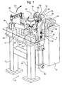
- figure 1 an overall perspective view of the machine,
- figure 2 is a partially broken side elevational view of the portion of the machine indicated in general A in figure 1, in which a movable element carrying a welding electrode is in a raised and withdrawn position,
- figure 3 is a view similar to that of figure 2, with the movable element in an intermediate position,
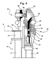
- figure 4 is a view similar to those of figures 2 and 3, with the movable element in a lowered working position, and
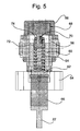
- figure 5 is a detail sectional view, taken in a greater scale in the plane indicated V-V in figure 3.
- Referring to figure 1, the welding machine represented comprises a frame designated in the whole by 10, which will be considered in the following.
- A
transformer 12 for feeding the welding current is arranged close to theframe 10, whose elements have not been represented since they are known per se. - The
frame 10 comprises, among other things, a pair ofuprights 14 which carry a horizontal metallic table 16. - The table 16 supports in turn a pair of
insulating blocks - In figures 2 to 4, the outline of a welding plane of the workpieces W is indicated P.
- A welding electrode is indicated 22, which is carried by a movable element, designated in the whole by 24, which will be referred to in the following.
- A pressure electrode for closing the electrical welding circuit is indicated 26, which, through the workpieces W, cooperates with the
platform 20. - In a known manner, the
pressure electrode 26 is carried by an oscillatingarm 28, which can be raised, according arrow F1, to a raised and withdrawn position in order to leave the space above theplatform 20 free and therefore to make easier to put down and remove the workpieces W. - Both the welding and
pressure electrodes transformer 12. - Referring now to figures 2 to 4, as well as to figure 1, the
frame 10 supports a columnar structure, designated in the whole by 30. - The
columnar structure 30 preferably comprises, as represented, a pair ofopposite body sides 32 between which themovable element 24 is arranged. - Respective
homologous slits 34 are formed in thebody sides 32, which jointly constitute a guide acting as a fixed cam, for a tracer unit, designated in the whole by 36. - The
tracer unit 36 is fastened to themovable element 24 and slidably engages the edges of theslits 34 which constitute the guide. - Each
slit 34 comprises a lowerlinear portion 34 and an upper tilted or deflectedportion 40. - The
tracer unit 36 preferably comprises, for eachslit 34, a pair of superimposed tracer rollers, lower 42 and upper 44, having a horizontal axis. - The
movable element 24 is articulated about the axis of thelower rollers 42. - The cylinder of a linear to-and-fro, hydraulic, pneumatic or
electrical actuator 46 is fixed to thetransformer 12 and/or to thebody sides 32, which has avertical rod 48 which is articulated about the horizontal axis of thelower rollers 42 of thetracer unit 36. - As it will be better understood in the following, the
single actuator 46 constitutes both the control means of the movements of the movable element and the pressure means for pressing the electrode on the workpieces W to be welded. - The travel of the
actuator rod 48 has a length such that, when thelower roller 42 of each pair ofrollers linear portion 40 of therespective slit 34 and theupper roller 44 of each pair is located at the upper deflectedportion 40 of therespective slit 34, themovable element 24 and itswelding electrode 22 is located in a raised and tilted or deflected position, illustrated in figure 2, in which theelectrode 22 is not superimposed to the workpieces W of sheet and does not interfere with the put down and the removal of them from up. - The arrangement is such that when both the
lower rollers 42 and theupper rollers 44 of thetracer unit 36 engage the lowerlinear portion 38 of theguide 34, such as in figures 4 and 5, theelectrode 22 is superimposed to theplatform 18 and is directed orthogonally towards the welding plane P. - In these conditions, a down return movement of the
rod 48 of theactuator 46 bring themovable element 24 down from the intermediate withdrawn and raised position of figure 3 to the lowered working position of figure 4 in which theelectrode 22 is applied perpendicularly on the upper workpiece of the workpieces W of sheet to be welded. - The working cycle for executing a welding will be better described in the following.
- Preferably, as represented, the
movable element 24 comprises a Γ-shaped body 50 with an upright 52 arranged between thebody sides 32, and which carries the tracer unit constituted by therollers upper bracket 54 supporting theelectrode 22. - Advantageously, yielding damping elastic means for applying the pressure of the
electrode 22 to the worpieces of sheet W are interposed between theupper bracket 54 of themovable element 24 and theelectrode 22, in the condition that will be described with reference to figure 4. - Preferably, as illustrated in figure 5, the
upper bracket 54 carries ahollow body 56 fastened to it, acting as a cylinder, which is closed at the top by ahead 58. - A cup-shaped 60 is mounted in the
hollow body 56, which acts as a piston and has abottom wall 62 to which theelectrode 22 is fixed. - The aforesaid dampeing elastic means are constituted by a
compression coil spring 64 which is contained in the cup-shaped body 60 and which counteracts on the one side against thebottom wall 62 and on the other side against thehead 58. An electrode-holder 66 is fixed at the bottom to thebottom wall 62, to which theelectrode 22 is fixed. - Preferably, a
load cell 68 is interposed between thespring 64 andhead 58, which acts as a pressure transducer in order to generate an electrical authorisation signal for the welding when, in the condition of figure 4, the welding pressure reaches a preset value. - The
load cell 68 is provided with a threadedtang 70 which is engaged in a threadedspacer bush 72. - A
lock nut 74 serves for blocking the coupling between thetang 70 and thebush 72. - In the condition of figure 4, the welding pressure is transmitted from the
electrode 22 to theload cell 68 through the electrode-holder 66, thebottom wall 62 of the cup-shaped body 60, thecoil spring 64, thespacer bush 72 and thetang 70. - A welding cycle will be now described by referring in succession to figures 2, 3 and 4.
- The welding cycle is preferably automatized, under the control of a programmer.
- While the
movable element 24 is in the raised and deflected position of figure 2, the workpieces of sheet W to be welded are positioned on theplatform 18, as well as on theplatform 20 of figure 1. - Once the workpieces W are positioned, the
actuator 46 is powered in the direction of the down travel of itsrod 48, which drives thetracer unit 36 downwards with it. - In this down movement, the
upper rollers 44 go down along thedeflected portion 40 of theguide 34, thelower rollers 42 begin to go down along the lowerlinear portion 38 of theguide 34 and themovable element 24 straightens according to arrow F2 of figure 3, by rotating about the axis of thelower rollers 42. - Once the
movable element 24 has reached the intemediate raised and straightened position of figure 3, the further downward return of therod 48 causes theelement 24 to go down until it reaches the working position of figure 4, in which theelectrode 22 presses the workpieces W perpendicularly to the welding plane P and to the workpieces themselves. - Preferably, an additional guide system is provided, which comprises a pair of
opposite rollers 76, carried by themovable element 24 and only one of which can be seen in figures 1 to 4. - In the downward movement of the
element 24 between the positions of figures 2 and 3, therollers 76 cooperate withrespective blocks 78 inserted on the twobody sides 32 and which constitute guide tracks for therollers 76, in order to counteract the reaction which would tend to cause theelement 24 to rotate in the direction opposite to that of arrow F2 of figure 3. - While the
electrode 22 is kept pressed on the workpieces W in the condition of figure 4, thanks to the force transmitted to it by theactuator 46, thetransformer 12 receives a signal from an electronic control unit and applies the welding current impulses to the workpieces W through theelectrode 22, so that the welding takes place. - Once the welding has been executed, the
actuator 46 causes themovable element 24 to go up again towards the raised and withdrawn position of figure 2, the welded workpieces W are removed and the machine is ready for a new welding cycle. - With reference to the drawings, a machine has been described as a non-limitative example, in which the welding plane P of the workpieces W is horizontal and the direction in which the
electrode 22 is applied on the workpieces W is vertical, but it will be understood that in a machine according to the invention these directions could be different from those illustrated.
Claims (6)
- Resistance welding machine for sheets, of the type comprising a frame (10) supporting on the one side a workpiece-holder platform (18) on which two or more superimposed workpieces of sheet (W) to be welded together can be supported and positioned, and on the other side a columnar structure (30) arranged close to the platform (18) and on which an element (24) carrying a welding electrode (22) is mounted, which element is movable between a withdrawn position, in which the electrode (22) is not superimposed to the workpieces (W) to be welded, and a working position, in which the electrode (22) is applied on the workpieces (W) perpendicularly to a welding plane (P), and in which control means are provided for causing the element (24) to move between the two aforesaid positions, pressure means for pressing the electrode (22) on the workpieces of sheet (W) and pressing together the workpieces themselves between the electrode (22) and the platform (18), and electric power means connected on the one side to the electrode (22) and on the other side to the platform (18) in order to allow a welding current to pass in the workpieces (W) when they are pressed together,
characterized in that the columnar structure (30) is provided with a guide (34) acting as a fixed cam and having a lower linear portion (38) perpendicular to the welding plane (P) and an upper deflected portion (40),
in that the movable element (24) carrying the welding electrode (22) is provided with a slidable tracer unit (36) which is in engagement with the guide (34) and is adapted to assume a deflected position, in which the electrode (22) is not superimposed to the workpieces (W) to be welded, when the tracer unit (36) is in engagement with the deflected portion (40) of the guide, and an intermediate straightened position, in which the electrode (22) is superimposed to the workpieces (W) to be welded and is directed perpendicularly towards the welding plane (P), when the tracer unit (36) is in engagement with the lower portion (38) of the guide,
in that the control means and the pressure means are jointly constituted by a linear to-and-fro actuator (46) having a rod (48) to which the tracer unit (36) is articulated in order to allow the element (24) to rotate between the two deflected and intermediate positions, and
in that the actuator (46) is adapted to produce both the aforesaid rotation of the movable element (24) and the linear movement of the movable element (24) between the intermediate position and the lowered working position. - Resistance welding machine according to claim 1,
characterized in that the columnar structure (30) comprises a pair of opposite body sides (32) between which the movable element is arranged (24),
in that the guide has the shape of a pair of homologous slits (34) formed in the body sides (32) and the tracer unit (36) comprises, for each slit (34), a pair of superimposed tracer rollers (42, 44) engaged in the slit itself,
in that the movable element (24) is articulated about the axis of the lower roller (42) of each pair of rollers, and
in that the travel of the rod (48) of the actuator (46) has a length such that, when the movable element (24) is at the deflected position, the lower roller (42) of each pair of rollers is at the top of the lower portion (38) of the respective slit (34) and the upper roller (44) of each pair of rollers is at the deflected portion (40) of the respective slit (34). - Resistance welding machine according to claim 1 or 2,
characterized in that the movable element (24) comprises a Γ-shaped body (50) with an upright (52) carrying the tracer unit (36) and an upper bracket (54) carrying the electrode (22) with the interposition of damping elastic means (64) which are yieldable in the direction of application of the pressure of the electrode (22) on the workpieces of sheet (W). - Resistance welding machine according to claim 3,
characterized in that a load cell (68) acting as a pressure transducer for generating an electrical signal of authorisation for the welding when the welding pressure reaches a preset value, is associated to the elastic means (64). - Resistance welding machine according to claim 3,
characterized in that the upper bracket (54) of the movable element (24) carries a hollow body (56) fastened to it, acting as a cylinder, which is closed at the top by a head (58),
in that a cup-shaped body (60) acting as a piston and having a bottom wall (62) to which the electrode is fixed, is slidably mounted in the hollow body (56), and
in that the elastic means are constituted by a compression coil spring (64) contained in the cup-shaped body (60) and counteracting on the one side against the aforesaid bottom wall (62) and on the other side against the aforesaid head (58). - Resistance welding machine according to claim 5,
characterized in that it comprises a load cell (68) interposed between the spring (64) and the head (58), which acts as a pressure transducer in order to generate an authorisation electrical signal for the welding when the welding pressure reaches a preset value.
Applications Claiming Priority (2)
| Application Number | Priority Date | Filing Date | Title |
|---|---|---|---|
| IT000047A ITTO20030047A1 (en) | 2003-01-28 | 2003-01-28 | RESISTANCE WELDING MACHINE FOR SHEETS |
| ITTO20030047 | 2003-01-28 |
Publications (3)
| Publication Number | Publication Date |
|---|---|
| EP1442819A2 true EP1442819A2 (en) | 2004-08-04 |
| EP1442819A3 EP1442819A3 (en) | 2005-08-10 |
| EP1442819B1 EP1442819B1 (en) | 2010-12-15 |
Family
ID=32652481
Family Applications (1)
| Application Number | Title | Priority Date | Filing Date |
|---|---|---|---|
| EP04001705A Expired - Lifetime EP1442819B1 (en) | 2003-01-28 | 2004-01-27 | Resistance welding machine for sheets |
Country Status (5)
| Country | Link |
|---|---|
| EP (1) | EP1442819B1 (en) |
| AT (1) | ATE491541T1 (en) |
| DE (1) | DE602004030498D1 (en) |
| ES (1) | ES2356074T3 (en) |
| IT (1) | ITTO20030047A1 (en) |
Cited By (11)
| Publication number | Priority date | Publication date | Assignee | Title |
|---|---|---|---|---|
| EP1785340A2 (en) | 2005-11-14 | 2007-05-16 | KGR S.r.l. | Apparatus for fixing the elements of a panel for a motor vehicle body and method for fixing such elements |
| JP2012035274A (en) * | 2010-08-04 | 2012-02-23 | Honda Motor Co Ltd | Welding gun |
| WO2012045763A1 (en) * | 2010-10-06 | 2012-04-12 | Siemens Aktiengesellschaft | Welding head with a force sensor, a spring and an adjusting element |
| WO2014079156A1 (en) * | 2012-11-23 | 2014-05-30 | 上汽通用五菱汽车股份有限公司 | Welding tongs |
| WO2015064582A1 (en) * | 2013-10-29 | 2015-05-07 | 本田技研工業株式会社 | Welding gun |
| CN106238891A (en) * | 2016-08-25 | 2016-12-21 | 浙江凯恩电池有限公司 | Semi-automatic spot welding machine |
| CN107627049A (en) * | 2017-10-30 | 2018-01-26 | 苏州工业职业技术学院 | A kind of special hot weld device for hot weld detection device |
| US9919417B2 (en) * | 2014-11-26 | 2018-03-20 | Concraft Holding Co., Ltd. | Direction-adjustable jig |
| CN110802321A (en) * | 2019-11-27 | 2020-02-18 | 衡阳市鑫晟新能源有限公司 | Lithium ion battery clamp |
| CN118991049A (en) * | 2024-09-30 | 2024-11-22 | 浙江汉博汽车传感器有限公司 | Sensor precision hot-melt welding machine |
| CN120095392A (en) * | 2024-11-11 | 2025-06-06 | 泰州正瑞机械科技有限公司 | Welding device for automobile parts processing |
Families Citing this family (1)
| Publication number | Priority date | Publication date | Assignee | Title |
|---|---|---|---|---|
| CN114173491B (en) * | 2021-11-29 | 2022-09-27 | 江西和兴光电有限公司 | A mounting structure for preventing deflection of electronic components |
Citations (1)
| Publication number | Priority date | Publication date | Assignee | Title |
|---|---|---|---|---|
| US4728767A (en) | 1985-10-18 | 1988-03-01 | Mazda Motor Corporation | Welding gun apparatus |
Family Cites Families (4)
| Publication number | Priority date | Publication date | Assignee | Title |
|---|---|---|---|---|
| US3509308A (en) * | 1966-03-15 | 1970-04-28 | Budd Co | Self-tilting equalizing welding gun |
| FR1476016A (en) * | 1966-03-21 | 1967-04-07 | Machine for performing electrical spot welds following orthogonal coordinates | |
| JPS58103977A (en) * | 1981-12-17 | 1983-06-21 | Nissan Motor Co Ltd | Spot welding gun |
| CA1321627C (en) * | 1988-06-22 | 1993-08-24 | Naoteru Katsura | Method and apparatus for supplying electric power to resistance welding gun |
-
2003
- 2003-01-28 IT IT000047A patent/ITTO20030047A1/en unknown
-
2004
- 2004-01-27 EP EP04001705A patent/EP1442819B1/en not_active Expired - Lifetime
- 2004-01-27 ES ES04001705T patent/ES2356074T3/en not_active Expired - Lifetime
- 2004-01-27 AT AT04001705T patent/ATE491541T1/en active
- 2004-01-27 DE DE602004030498T patent/DE602004030498D1/en not_active Expired - Lifetime
Patent Citations (1)
| Publication number | Priority date | Publication date | Assignee | Title |
|---|---|---|---|---|
| US4728767A (en) | 1985-10-18 | 1988-03-01 | Mazda Motor Corporation | Welding gun apparatus |
Cited By (21)
| Publication number | Priority date | Publication date | Assignee | Title |
|---|---|---|---|---|
| EP1785340A2 (en) | 2005-11-14 | 2007-05-16 | KGR S.r.l. | Apparatus for fixing the elements of a panel for a motor vehicle body and method for fixing such elements |
| EP1785340A3 (en) * | 2005-11-14 | 2008-07-23 | KGR S.p.A. | Apparatus for fixing the elements of a panel for a motor vehicle body and method for fixing such elements |
| JP2012035274A (en) * | 2010-08-04 | 2012-02-23 | Honda Motor Co Ltd | Welding gun |
| CN102371427A (en) * | 2010-08-04 | 2012-03-14 | 本田技研工业株式会社 | Welding gun |
| EP2415550A3 (en) * | 2010-08-04 | 2013-06-12 | Honda Motor Co., Ltd. | Welding gun |
| US8853595B2 (en) | 2010-08-04 | 2014-10-07 | Honda Motor Co., Ltd. | Welding gun |
| CN102371427B (en) * | 2010-08-04 | 2015-02-11 | 本田技研工业株式会社 | welding torch |
| WO2012045763A1 (en) * | 2010-10-06 | 2012-04-12 | Siemens Aktiengesellschaft | Welding head with a force sensor, a spring and an adjusting element |
| WO2014079156A1 (en) * | 2012-11-23 | 2014-05-30 | 上汽通用五菱汽车股份有限公司 | Welding tongs |
| CN105682846A (en) * | 2013-10-29 | 2016-06-15 | 本田技研工业株式会社 | Welding gun |
| WO2015064582A1 (en) * | 2013-10-29 | 2015-05-07 | 本田技研工業株式会社 | Welding gun |
| JP6086990B2 (en) * | 2013-10-29 | 2017-03-01 | 本田技研工業株式会社 | Welding gun |
| CN105682846B (en) * | 2013-10-29 | 2018-04-17 | 本田技研工业株式会社 | Welding gun |
| US10307858B2 (en) | 2013-10-29 | 2019-06-04 | Honda Motor Co., Ltd. | Welding gun |
| US9919417B2 (en) * | 2014-11-26 | 2018-03-20 | Concraft Holding Co., Ltd. | Direction-adjustable jig |
| CN106238891A (en) * | 2016-08-25 | 2016-12-21 | 浙江凯恩电池有限公司 | Semi-automatic spot welding machine |
| CN107627049A (en) * | 2017-10-30 | 2018-01-26 | 苏州工业职业技术学院 | A kind of special hot weld device for hot weld detection device |
| CN107627049B (en) * | 2017-10-30 | 2024-02-02 | 苏州工业职业技术学院 | A special heat welding device for heat welding testing equipment |
| CN110802321A (en) * | 2019-11-27 | 2020-02-18 | 衡阳市鑫晟新能源有限公司 | Lithium ion battery clamp |
| CN118991049A (en) * | 2024-09-30 | 2024-11-22 | 浙江汉博汽车传感器有限公司 | Sensor precision hot-melt welding machine |
| CN120095392A (en) * | 2024-11-11 | 2025-06-06 | 泰州正瑞机械科技有限公司 | Welding device for automobile parts processing |
Also Published As
| Publication number | Publication date |
|---|---|
| ES2356074T3 (en) | 2011-04-04 |
| ITTO20030047A1 (en) | 2004-07-29 |
| DE602004030498D1 (en) | 2011-01-27 |
| ATE491541T1 (en) | 2011-01-15 |
| EP1442819B1 (en) | 2010-12-15 |
| EP1442819A3 (en) | 2005-08-10 |
Similar Documents
| Publication | Publication Date | Title |
|---|---|---|
| EP1442819B1 (en) | Resistance welding machine for sheets | |
| CN215356673U (en) | Spot welding machine with automatic positioning function | |
| CN217513045U (en) | Electronic component terminal spot welding machine | |
| CN118046169B (en) | Battery box punches and welding positioning centre gripping combination frock | |
| CN216264332U (en) | Door handle welding machine | |
| KR20150052984A (en) | Spot welding device for brush card | |
| CN216729957U (en) | Workpiece fixing device of wire cutting machine tool | |
| US4451722A (en) | Fusing machine | |
| CN218193548U (en) | Positioning tool with limiting structure | |
| JP2011206808A (en) | Welding equipment | |
| CN213915627U (en) | Edge folding device | |
| CN212665174U (en) | Welding machine structure capable of controlling distance between two ends of stirrup | |
| CN108971723A (en) | A kind of oven Special resistance welding machine | |
| CN211588878U (en) | Independent type pressure spot welding device | |
| CN213998180U (en) | Adjustable energy-saving environment-friendly butt welding machine | |
| CN219131096U (en) | Controllable welding angle type roll welding equipment | |
| CN218225300U (en) | Workpiece positioning seat for argon arc welding machine | |
| SU740447A1 (en) | Apparatus for welding-on contacts | |
| CN221337064U (en) | Safety protection device of spot welder | |
| CN220050536U (en) | Movable rack of welding machine | |
| CN218253366U (en) | Energy storage type welding machine | |
| CN220698522U (en) | Welding fixing tool for automatic ultrasonic welding machine | |
| CN222735545U (en) | Reactor terminal crimping device | |
| EP4059648B1 (en) | A welding machine with a plurality of torches and a plurality of grounding contacts | |
| CN215467700U (en) | Press machine buffer mechanism |
Legal Events
| Date | Code | Title | Description |
|---|---|---|---|
| PUAI | Public reference made under article 153(3) epc to a published international application that has entered the european phase |
Free format text: ORIGINAL CODE: 0009012 |
|
| AK | Designated contracting states |
Kind code of ref document: A2 Designated state(s): AT BE BG CH CY CZ DE DK EE ES FI FR GB GR HU IE IT LI LU MC NL PT RO SE SI SK TR |
|
| AX | Request for extension of the european patent |
Extension state: AL LT LV MK |
|
| PUAL | Search report despatched |
Free format text: ORIGINAL CODE: 0009013 |
|
| AK | Designated contracting states |
Kind code of ref document: A3 Designated state(s): AT BE BG CH CY CZ DE DK EE ES FI FR GB GR HU IE IT LI LU MC NL PT RO SE SI SK TR |
|
| AX | Request for extension of the european patent |
Extension state: AL LT LV MK |
|
| 17P | Request for examination filed |
Effective date: 20060124 |
|
| AKX | Designation fees paid |
Designated state(s): AT BE BG CH CY CZ DE DK EE ES FI FR GB GR HU IE IT LI LU MC NL PT RO SE SI SK TR |
|
| 17Q | First examination report despatched |
Effective date: 20060929 |
|
| RAP1 | Party data changed (applicant data changed or rights of an application transferred) |
Owner name: KGR S.P.A. |
|
| GRAP | Despatch of communication of intention to grant a patent |
Free format text: ORIGINAL CODE: EPIDOSNIGR1 |
|
| GRAS | Grant fee paid |
Free format text: ORIGINAL CODE: EPIDOSNIGR3 |
|
| GRAA | (expected) grant |
Free format text: ORIGINAL CODE: 0009210 |
|
| AK | Designated contracting states |
Kind code of ref document: B1 Designated state(s): AT BE BG CH CY CZ DE DK EE ES FI FR GB GR HU IE IT LI LU MC NL PT RO SE SI SK TR |
|
| REG | Reference to a national code |
Ref country code: CH Ref legal event code: EP Ref country code: GB Ref legal event code: FG4D |
|
| REG | Reference to a national code |
Ref country code: IE Ref legal event code: FG4D |
|
| REF | Corresponds to: |
Ref document number: 602004030498 Country of ref document: DE Date of ref document: 20110127 Kind code of ref document: P |
|
| REG | Reference to a national code |
Ref country code: SE Ref legal event code: TRGR |
|
| REG | Reference to a national code |
Ref country code: ES Ref legal event code: FG2A Ref document number: 2356074 Country of ref document: ES Kind code of ref document: T3 Effective date: 20110404 |
|
| REG | Reference to a national code |
Ref country code: NL Ref legal event code: VDEP Effective date: 20101215 |
|
| PG25 | Lapsed in a contracting state [announced via postgrant information from national office to epo] |
Ref country code: BG Free format text: LAPSE BECAUSE OF FAILURE TO SUBMIT A TRANSLATION OF THE DESCRIPTION OR TO PAY THE FEE WITHIN THE PRESCRIBED TIME-LIMIT Effective date: 20110315 Ref country code: NL Free format text: LAPSE BECAUSE OF FAILURE TO SUBMIT A TRANSLATION OF THE DESCRIPTION OR TO PAY THE FEE WITHIN THE PRESCRIBED TIME-LIMIT Effective date: 20101215 Ref country code: CY Free format text: LAPSE BECAUSE OF FAILURE TO SUBMIT A TRANSLATION OF THE DESCRIPTION OR TO PAY THE FEE WITHIN THE PRESCRIBED TIME-LIMIT Effective date: 20101215 Ref country code: SI Free format text: LAPSE BECAUSE OF FAILURE TO SUBMIT A TRANSLATION OF THE DESCRIPTION OR TO PAY THE FEE WITHIN THE PRESCRIBED TIME-LIMIT Effective date: 20101215 Ref country code: FI Free format text: LAPSE BECAUSE OF FAILURE TO SUBMIT A TRANSLATION OF THE DESCRIPTION OR TO PAY THE FEE WITHIN THE PRESCRIBED TIME-LIMIT Effective date: 20101215 |
|
| PG25 | Lapsed in a contracting state [announced via postgrant information from national office to epo] |
Ref country code: EE Free format text: LAPSE BECAUSE OF FAILURE TO SUBMIT A TRANSLATION OF THE DESCRIPTION OR TO PAY THE FEE WITHIN THE PRESCRIBED TIME-LIMIT Effective date: 20101215 Ref country code: PT Free format text: LAPSE BECAUSE OF FAILURE TO SUBMIT A TRANSLATION OF THE DESCRIPTION OR TO PAY THE FEE WITHIN THE PRESCRIBED TIME-LIMIT Effective date: 20110415 Ref country code: GR Free format text: LAPSE BECAUSE OF FAILURE TO SUBMIT A TRANSLATION OF THE DESCRIPTION OR TO PAY THE FEE WITHIN THE PRESCRIBED TIME-LIMIT Effective date: 20110316 Ref country code: BE Free format text: LAPSE BECAUSE OF FAILURE TO SUBMIT A TRANSLATION OF THE DESCRIPTION OR TO PAY THE FEE WITHIN THE PRESCRIBED TIME-LIMIT Effective date: 20101215 |
|
| PG25 | Lapsed in a contracting state [announced via postgrant information from national office to epo] |
Ref country code: RO Free format text: LAPSE BECAUSE OF FAILURE TO SUBMIT A TRANSLATION OF THE DESCRIPTION OR TO PAY THE FEE WITHIN THE PRESCRIBED TIME-LIMIT Effective date: 20101215 Ref country code: MC Free format text: LAPSE BECAUSE OF NON-PAYMENT OF DUE FEES Effective date: 20110131 Ref country code: SK Free format text: LAPSE BECAUSE OF FAILURE TO SUBMIT A TRANSLATION OF THE DESCRIPTION OR TO PAY THE FEE WITHIN THE PRESCRIBED TIME-LIMIT Effective date: 20101215 |
|
| REG | Reference to a national code |
Ref country code: CH Ref legal event code: PL |
|
| PLBE | No opposition filed within time limit |
Free format text: ORIGINAL CODE: 0009261 |
|
| STAA | Information on the status of an ep patent application or granted ep patent |
Free format text: STATUS: NO OPPOSITION FILED WITHIN TIME LIMIT |
|
| REG | Reference to a national code |
Ref country code: IE Ref legal event code: MM4A |
|
| PG25 | Lapsed in a contracting state [announced via postgrant information from national office to epo] |
Ref country code: DK Free format text: LAPSE BECAUSE OF FAILURE TO SUBMIT A TRANSLATION OF THE DESCRIPTION OR TO PAY THE FEE WITHIN THE PRESCRIBED TIME-LIMIT Effective date: 20101215 Ref country code: LI Free format text: LAPSE BECAUSE OF NON-PAYMENT OF DUE FEES Effective date: 20110131 Ref country code: CH Free format text: LAPSE BECAUSE OF NON-PAYMENT OF DUE FEES Effective date: 20110131 |
|
| 26N | No opposition filed |
Effective date: 20110916 |
|
| REG | Reference to a national code |
Ref country code: DE Ref legal event code: R097 Ref document number: 602004030498 Country of ref document: DE Effective date: 20110916 |
|
| PG25 | Lapsed in a contracting state [announced via postgrant information from national office to epo] |
Ref country code: IE Free format text: LAPSE BECAUSE OF NON-PAYMENT OF DUE FEES Effective date: 20110127 |
|
| PG25 | Lapsed in a contracting state [announced via postgrant information from national office to epo] |
Ref country code: LU Free format text: LAPSE BECAUSE OF NON-PAYMENT OF DUE FEES Effective date: 20110127 |
|
| PG25 | Lapsed in a contracting state [announced via postgrant information from national office to epo] |
Ref country code: HU Free format text: LAPSE BECAUSE OF FAILURE TO SUBMIT A TRANSLATION OF THE DESCRIPTION OR TO PAY THE FEE WITHIN THE PRESCRIBED TIME-LIMIT Effective date: 20101215 |
|
| PGFP | Annual fee paid to national office [announced via postgrant information from national office to epo] |
Ref country code: SE Payment date: 20140121 Year of fee payment: 11 Ref country code: CZ Payment date: 20140116 Year of fee payment: 11 |
|
| PGFP | Annual fee paid to national office [announced via postgrant information from national office to epo] |
Ref country code: AT Payment date: 20140127 Year of fee payment: 11 |
|
| PGFP | Annual fee paid to national office [announced via postgrant information from national office to epo] |
Ref country code: GB Payment date: 20140116 Year of fee payment: 11 |
|
| REG | Reference to a national code |
Ref country code: SE Ref legal event code: EUG |
|
| REG | Reference to a national code |
Ref country code: AT Ref legal event code: MM01 Ref document number: 491541 Country of ref document: AT Kind code of ref document: T Effective date: 20150127 |
|
| GBPC | Gb: european patent ceased through non-payment of renewal fee |
Effective date: 20150127 |
|
| PG25 | Lapsed in a contracting state [announced via postgrant information from national office to epo] |
Ref country code: CZ Free format text: LAPSE BECAUSE OF NON-PAYMENT OF DUE FEES Effective date: 20150127 Ref country code: GB Free format text: LAPSE BECAUSE OF NON-PAYMENT OF DUE FEES Effective date: 20150127 |
|
| PG25 | Lapsed in a contracting state [announced via postgrant information from national office to epo] |
Ref country code: SE Free format text: LAPSE BECAUSE OF NON-PAYMENT OF DUE FEES Effective date: 20150128 Ref country code: AT Free format text: LAPSE BECAUSE OF NON-PAYMENT OF DUE FEES Effective date: 20150127 |
|
| REG | Reference to a national code |
Ref country code: FR Ref legal event code: PLFP Year of fee payment: 13 |
|
| REG | Reference to a national code |
Ref country code: FR Ref legal event code: PLFP Year of fee payment: 14 |
|
| REG | Reference to a national code |
Ref country code: FR Ref legal event code: PLFP Year of fee payment: 15 |
|
| PGFP | Annual fee paid to national office [announced via postgrant information from national office to epo] |
Ref country code: ES Payment date: 20180214 Year of fee payment: 15 Ref country code: DE Payment date: 20180328 Year of fee payment: 15 |
|
| PGFP | Annual fee paid to national office [announced via postgrant information from national office to epo] |
Ref country code: TR Payment date: 20180126 Year of fee payment: 15 Ref country code: IT Payment date: 20180129 Year of fee payment: 15 Ref country code: FR Payment date: 20180122 Year of fee payment: 15 |
|
| REG | Reference to a national code |
Ref country code: DE Ref legal event code: R119 Ref document number: 602004030498 Country of ref document: DE |
|
| PG25 | Lapsed in a contracting state [announced via postgrant information from national office to epo] |
Ref country code: FR Free format text: LAPSE BECAUSE OF NON-PAYMENT OF DUE FEES Effective date: 20190131 Ref country code: DE Free format text: LAPSE BECAUSE OF NON-PAYMENT OF DUE FEES Effective date: 20190801 |
|
| PG25 | Lapsed in a contracting state [announced via postgrant information from national office to epo] |
Ref country code: IT Free format text: LAPSE BECAUSE OF NON-PAYMENT OF DUE FEES Effective date: 20190127 |
|
| REG | Reference to a national code |
Ref country code: ES Ref legal event code: FD2A Effective date: 20200310 |
|
| PG25 | Lapsed in a contracting state [announced via postgrant information from national office to epo] |
Ref country code: ES Free format text: LAPSE BECAUSE OF NON-PAYMENT OF DUE FEES Effective date: 20190128 |
|
| PG25 | Lapsed in a contracting state [announced via postgrant information from national office to epo] |
Ref country code: TR Free format text: LAPSE BECAUSE OF NON-PAYMENT OF DUE FEES Effective date: 20190127 |