FIELD OF THE INVENTION
The present invention relates to massage machines
comprising a massage device.
BACKGROUND OF THE INVENTION
Massage machines include those comprising a massage
device mounted on the backrest of a chair and movable upward
and downward for massaging the person to be treated by tapping,
kneading or exerting finger pressure or acupressure on the body
portion extending from the neck to the shoulders or to the waist.
Massage machines are operated using an operating control
device electrically connected to the machine. The operating
control device is manipulated for adjusting the angle of
inclination of the backrest, selecting various massage
movements, performing various control procedures, and
recognizing the movement with reference to a display provided
on the control device (see, for example, the publication of
JP-A No. 2002-233560, page 3, para. 0012 and para. 0013, and
FIG. 4).
The operating control device is adapted to direct all
operations of the massage machine including operations or
movements which are not used frequently. The display provided
on the device for showing particular modes of massage movements
make the operating control device large-sized and heavier.
The operating control device therefore has the problem of being
difficult to use and causing fatigue to the hand manipulating
the device.
SUMMARY OF THE INVENTION
An object of the present invention is to provide a massage
machine which comprises an operating control device easily
usable and which gives a massage to the user in a relaxed state.
To fulfill the above object, the present invention
provides a massage machine having a massage device
incorporated in a chair for massaging the person to be treated,
said massage machine comprises a main operating unit and an
auxiliary operating unit, each to be manipulated by the person,
the main operating unit and the auxiliary operating unit being
adapted for directing at least one of movements of the massage
device and other elements, the auxiliary operating unit being
movable relative to the chair.
The auxiliary operating unit is adapted to direct, for
example, a specified movement which is performed frequently
among all the movements to be directed by the main operating
unit. Therefore the auxiliary operating unit can be compacted,
lightweight and held by hand easily since the auxiliary
operating unit is free to move relative to the chair.
Accordingly, the unit is unlikely to cause fatigue to the hand
even if held for a prolonged period of time, enabling the user
to be massaged in a relaxed state.
The auxiliary operating unit is adapted to direct, for
example, an auxiliary movement which is performed frequently
among all the movements to be directed by the main operating
unit. Therefore the auxiliary operating unit can be compacted,
lightweight and held by hand easily since the auxiliary
operating unit is free to move relative to the chair.
Accordingly, the unit is unlikely to cause fatigue to the hand
even if held for a prolonged period of time, enabling the user
to be massaged in a relaxed state.
With the massage machines described above, the specified
or auxiliary movement is a movement which is performed
frequently during massaging, so that most operations can be
directed by the auxiliary operating unit without using the main
operating unit. This makes the massage machine more
convenient to use.
The massage machine further comprises a reclining
mechanism for inclining or raising a backrest of the chair,
and the angle of inclination of the backrest is made
controllable as directed by the auxiliary operating unit. The
adjustment of the inclination of the backrest, that is made
frequently, can therefore be easily directed by the auxiliary
operating unit.
The backrest of the chair is provided with the massage
device upwardly or downwardly movably, and the massage device
is movable upward or downward as directed by the auxiliary
operating unit. While the massage device is moved upward or
downward frequently during massaging, the massage machine is
then so movable easily as directed by the auxiliary operating
unit.
The chair is pivotally movably provided with a footrest
at a forward end of a seat thereof, and the angle of pivotal
movement of the footrest is controllable as directed by the
auxiliary operating unit. While the angle of pivotal movement
of the footrest is adjusted frequently during massaging, this
adjustment is then easily made as directed by the auxiliary
operating unit.
The specified or auxiliary movement is a massage movement
of a particular intensity. The intensity of the massage
movement of the massage device, which is adjusted frequently
during massaging, can therefore be adjusted easily by the
auxiliary operating unit.
The auxiliary operating unit is in the form of a hollow
cylinder having a cut plane portion, so that the unit can be
held with good stability with the thumb placed on the cut plane
portion.
The cut plane portion has control means for directing
the specified or auxiliary movement. This enables the user
to hold the unit with good stability with the thumb placed on
the plane portion and also to manipulate the control means by
moving the thumb.
The cut plane portion has a rest for placing the thumb
thereon. The auxiliary operating unit can then be gripped
reliably at the specified portion.
The auxiliary operating unit is provided with means for
detecting physiological data produced by massaging the person
to be treated, whereby the physiological data can be detected
while the auxiliary operating unit is being held by hand, and
an optimum massage can be given to the user based on the data.
BRIEF DESCRIPTION OF THE DRAWINGS
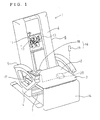
FIG. 1 is a perspective view showing a massage machine
according to an embodiment of the invention, with a cover
removed from a backrest;
FIG. 2 is a perspective view of a main operating unit
of the massage machine;
FIG. 3 is a perspective view showing the main operating
unit of the massage machine with a lid of the unit opened;
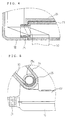
FIG. 4 is an enlarged fragmentary front view in section
of the main operating unit of the massage machine to show a
pivot and the surrounding thereof;
FIG. 5 is an enlarged fragmentary side elevation partly
broken away and showing the pivot of the main operating unit
of the massage machine and the surrounding thereof;
FIG. 6 is a front view of a flat cable for use in the
main operating unit of the massage machine;
FIG. 7 is a front view of a flat cable to be compared
with the flat cable for use in the main operating unit of the
massage machine;
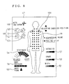
FIG. 8 is an enlarged fragmentary view of a liquid crystal
display of the main operating unit of the massage machine;
FIG. 9 is a plan view of an auxiliary operating unit of
the massage machine;
FIG. 10 is a side elevation of the auxiliary operating
unit of the massage machine;
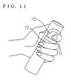
FIG. 11 is a perspective view of the massage machine
auxiliary operating unit as held by hand; and
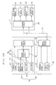
FIG. 12 is a control circuit diagram of the massage
machine.
DESCRIPTION OF THE PREFERRED EMBODIMENT
An embodiment of the present invention will be described
with reference to a massage machine shown in FIGS. 1 to 12.
The tiptoe side of the person to be treated and sitting in a
seat 3 will be referred to as the "front," and his or her back
side as the "rear."
With reference to FIG. 1, a massage machine 1 comprises
a massage device 11 which can be incorporated in a chair 8.
The chair 8 comprises the seat 3 covered with a cushion
2, legs 4 provided at opposite sides of the seat 3, armrests
5 positioned above the respective legs 4, a backrest 6 provided
on the rear side of the seat 3, and a frame assembly 7 serving
as a framework for these components.
The backrest 6 has its lower portion pivoted to the rear
end of the seat 3 and is inclined or raised to an angle desired
by the user by a reclining mechanism (not shown) having an
inclining motor 9 serving as a drive source.
The massage device 11 is incorporated in the backrest
6 and is movable upward and downward by a lift motor 10. The
massage device 11 comprises a pair of left and right therapeutic
members 13, 13 projecting forward from the backrest 6 and
movable by a therapeutic motor 12 serving as a drive source.
By combinations of some of the upward and downward movement
of the massage device 11 and the forward, rearward, leftward
and rightward movements of the therapeutic members 13, the
person to be treated and sitting in the machine 1 can be given
a kneading massage, tapping massage, acupressure massage,
tapping-kneading massage or the like over his or her body
portion from the neck to the waist. The backrest 6 is covered
with a cushion (not shown).
Pivoted to the front end of the seat 3 is the upper end
of a footrest 14 for placing the calves of the user thereon.
The angle of the footrest 14 is adjustable by a turning motor
15.
An operating control device 16 is used for directing
various operations or movements of the massage machine 1. The
operating control device 16 comprises a main operating unit
18 to be placed on a support portion 17 provided on one of the
armrests 5, and an auxiliary operating unit 19 to be held by
the user with one hand and freely movable relative to the chair
8. These operating units 18, 19 are electrically connected
to a control circuit 20 provided below the seat 3 by respective
wiring lines 21 and 22.
With reference to FIGS. 2 and 3, the main operating unit
18 comprises a base portion 23, a lid 24 attached to one end
of the base portion 23 and foldable to cover the base portion
23, a liquid crystal display 26 supported by a pivot 25 (see
FIGS. 4 and 5) provided at the other end of the base portion
23, control means 27 provided on the base portion 23 and the
lid 24, and a remote control circuit 28 provided on the base
portion 23. As shown in FIG. 12, the control means 27 feeds
an output to the remote control circuit 28. The remote control
circuit 28 is connected to the control circuit 20 of the chair
8 by the wiring line 21.
The control means 27 includes a stiffness relieving
switch 29, fatigue relieving switch 30, relaxation switch 31
and slimming switch 32 which are provided on the lid 14. The
stiffness relieving switch 29 is used for selecting a stiffness
relieving course wherein an acupressure movement is mainly
performed, the fatigue relieving switch 30 for selecting a
fatigue relieving course wherein a tapping movement is mainly
performed, the relaxation switch 31 for selecting a relaxation
course wherein a kneading movement is mainly conducted, and
the slimming switch 32 for selecting a slimming-down course
wherein acupressure is applied mainly to points in the body
which are said to be effective for slimming down.
The base portion 23 is provided with a power source switch
33 which is left exposed at all times regardless of the opening
or closing of the lid 24. When the power source is turned on
by pushing the power source switch 33, the four switches 29,
30, 31, 32 on the lid 24 can be manipulated in the case where
the lid 24 is closed. When the lid 24 is opened as shown in
FIG. 3, only an automatic switch 34 for directing an automatic
course and a manual switch 35 for directing a manual course
can be manipulated.
The part of the base portion 23 which is covered with
the lid 24 as closed is provided with a neck/shoulder switch
36 and a waist switch 37 which are arranged in a row along with
the automatic switch 34 and which can be manipulated when the
automatic switch 34 is pushed. Also arranged in the
above-mentioned part are an acupressure switch 38, tapping
switch 39, kneading switch 40, tapping-kneading switch 41,
intensity adjusting switch 42, speed adjusting switch 43,
width adjusting switch 44 and shoulder position adjusting
switch 45 which become ready for manipulation when the manual
switch 35 is pushed.
The neck/shoulder switch 36 is used for directing a
neck/shoulder course wherein massage movements, such as a
kneading movement, tapping movement and acupressure movement,
are performed in a predetermined sequence mainly over the area
of the neck through the shoulder. The waist switch 37 serves
to direct a waist course wherein massage movements, such as
a kneading movement, tapping movement and acupressure movement,
are performed in a predetermined sequence mainly over the waist
area.
The acupressure switch 38, tapping switch 39, kneading
switch 40 and tapping-kneading switch 41 serve to direct
massage movements by the therapeutic members 13, 13, namely,
an acupressure movement, tapping movement, kneading movement
and tapping-kneading movement including tapping and kneading
in combination, respectively. The intensity adjusting switch
42 and the speed adjusting switch 43 direct the intensity of
each massage movement (the amount of forward pushing-out of
the therapeutic members 13) and the speed of each massage
movement, respectively. The width adjusting switch 44 gives
direction about the distance between the therapeutic members
13, 13. When the shoulder position adjusting switch 45 is
pushed on its upper side, the switch directs an upward movement
of the massage device 11, and when pushed on its lower side,
the switch 45 directs a downward movement of the massage device
11. The shoulder position providing a reference position for
the automatic course is adjustable also by the switch 45.
With reference to FIG. 8, an image of human body is shown
on the liquid crystal display 26 centrally thereof. A
plurality of therapeutic sites are represented as spots as
indicated at 46. During massaging, the particular therapeutic
site 46 to be massaged is lighted up by the control circuit
20 by way of the remote control circuit 28 to visually indicate
the site of therapy. Furthermore, double-circles are
represented as at 46a as shown in FIG. 8 at locations where
the degree of stiffness is found to be greater than a
predetermined value with reference to the output of the
physiological data measuring means 81 to be described later.
The representation 46a makes the user to recognize the site
of great degree of stiffness, which can be relieved
concentrically by manipulating switches.
The liquid crystal display 26 has at its left upper
portion a grip indicator 47 which is lighted up during
measurement with the electrodermal resistance measuring means
74 to be described later. Disposed below this grip indicator
47 is an auto indicator 48 which is lighted up when an automatic
course, i.e., the neck/shoulder course, waist course,
stiffness relieving course, fatigue relieving course,
relaxation course or slimming course, is selected. Arranged
below the auto indicator 48 are indicators 49 for various
massage movements, i.e., an acupressure indicator 50 which is
lighted up for an acupressure movement, a kneading indicator
51 to be lighted up for a kneading movement, a tapping indictor
52 to be lighted up for a tapping movement, and a
tapping-kneading indicator 53 to be lighted up for a
tapping-kneading movement.
Arranged at the left lower portion of the liquid crystal
display 26 are a stiffness degree indicator 54 showing on the
right side the decree of stiffness stepwise in seven levels
relative to a reference position indicated by a black dot, and
showing the degree of relaxation stepwise in three levels on
the left side, a body form indicator 55 to be lighted up when
the body form is detected as will be described later, and a
pressure indicator 56 for indicating in four levels the
pressure to be applied to the body at this time.
Provided at the right lower portion of the liquid crystal
display 26 are an intensity indicator 57 and a speed indicator
58 for indicating the intensity and speed of each massage
movement, respectively, in three levels, and a width indicator
59 for indicating the distance between the therapeutic members
13, 13.
With reference to FIG. 6, the liquid crystal display 26
is connected to the remote control circuit 28 provided in the
base portion 23 by a flat cable 60 in the form of a straight
flat plate. Stated more specifically, the flat cable 60
extends from the base portion 23 into the display 26 as
helically wound within the pivot 25 as shown in FIGS. 4 and
5. The pivot 25 extends into the display 26 and has a length
not permitting the forward end thereof to interfere with the
flat cable 60, such that the pivot end will not wear away or
otherwise damage and break the cable 60. Further the portion
of the pivot 25 projecting into the display 26 is cut out greatly
to a U shape at its upper part 25a so as to make the angle of
the display 26 adjustable relative to the base portion 23 over
a predetermined range and to make the display pivotally movable
while permitting the flat cable to bend without being subjected
to an objectionable force.
Thus, the cable 60 is rendered free of the likelihood
of breaking, obviating the need to use an expensive flat cable
61 which is made in a bent form at the portion thereof to be
inserted into the pivot 25 as shown in FIG. 7 to result in a
cost reduction.
The liquid crystal display 26 is pivotally movable
relative to the base portion 23 and therefore has the following
advantage. If the backrest 6 is raised or inclined to an angle
desired by the user or the eyes are positioned at a different
level because a user of different height is seated in the chair
when the machine is used with the main operating unit 18 placed
on the support portion 17 as seen in FIG. 1, the liquid crystal
display 26 can be pivotally movable to an angle at which the
display is easy to view. Accordingly, the display 26 is
convenient to use because the user need not raise his or her
body to watch the display 26.
The auxiliary operating unit 19 is in the form of a hollow
cylinder having a cut plane portion 62. As shown in FIGS. 9
to 11, the cut plane portion 62 has at its upper end a rest
80 for placing the thumb thereon. The rest 80 is a projection
projecting from the plane portion 62 and having the same height
as the following switches of control means 63 provided on the
plane portion 62. The switches are provided in the vicinity
of the thumb rest 80 and are easy to manipulate by moving the
thumb.
Indicated at 65 is a repeat switch disposed on the plane
portion 62 at one side the support portion 80. When pushed
during each automatic course, the repeat switch 65 directs the
repetition of the massage movement preceding that of the
current automatic course.
Indicated at 66 is a turn switch disposed below the repeat
switch 65. When pushed at its upper side, the turn switch 66
directs the footrest 14 to pivotally move upward, and when
pushed at its lower side, the switch directs downward turn of
the footrest 14.
Indicated at 67 is an inclining switch disposed beside
the turn switch 66. When pushed at its upper side, the
inclining switch 67 directs raising of the backrest 6, while
when pushed at its lower side, the switch directs the backrest
6 to incline backward.
Indicated at 68 is a shoulder position adjusting switch
provided below the turn switch 66. Like the one provided on
the main operating unit 18, this switch 68 moves the massage
device 11 upward when pushed at its upper side and moves the
device 11 downward when pushed at its lower side. This switch
68 is also adapted to direct the adjustment of the shoulder
position serving as a reference position for the automatic
courses.
Indicated at 69 is an intensity adjusting switch disposed
beside the shoulder position adjusting switch 68. When pushed
at its upper side, the switch increases the intensity of each
massage movement by pushing out the therapeutic members 13
forward, or when pushed at its lower side, the switch reduces
the intensity of each massage movement by retracting the
therapeutic members 13 rearward.
The switches of the control means 63 on the auxiliary
operating unit 19 serve to direct movements which are
frequently directed during massaging. Among these switches,
the repeat switch 65, turn switch 66 and inclining switch 67
direct the movements which can not be directed by the main
operating unit 18, while the shoulder position adjusting
switch 68 and the intensity adjusting switch 69 direct the
movements which can be directed also by the main operating unit
18.
The cylindrical surface of the auxiliary operating unit
19 opposite to the plane portion 62 is recessed at the portion
thereof with which the first finger (the index finger)
spontaneously comes into contact when the unit 19 is gripped
with the thumb placed on the rest 80, whereby a first finger
rest 70 is provided. Provided below the first finger rest 70
is a separator 71 for preventing the first finger bearing on
the rest 70 from coming into contact with the second finger.
This permits the electrodermal resistance measuring means 74
to be described below to give an accurate value when measuring
the electrical resistance. Provided below the separator 71
is a second finger rest 72 at at least the portion with which
the second finger (the middle finger) comes into contact.
One of the first finger rest 70 and the second finger
rest 72 is provided with pulse measuring means 73 serving as
physiological data measuring means 81 shown in FIG. 12 for
measuring the pulse rate of the person to be treated. The two
rests 70 and 72 are provided with the electrodermal resistance
measuring means 74 for measuring the electrical resistance of
the skin to check the amount of perspiration. This measuring
means 74 comprises an electrode 75 provided in the first finger
rest 70 and an electrode 76 provided in the second finger rest
72 for measuring the electrical resistance therebetween. The
term "physiological data" as used herein refers to
physiological quantities which vary with the degree of
stiffness or the state of relaxation when the person to be
treated is massaged. These quantities include the temperature
of the skin, electroencepharograph, respiratory rate, blood
pressure, etc. in addition to the pulse rate. Means for
measuring these items of data may be used.
The control means 63 and one of the electrodes, 76, are
connected to a remote control circuit 77, and the pulse
measuring means 73 and the other electrode 75 are connected
via a sensor processing circuit 78 to the remote control circuit
77. The remote control circuit 77 is electrically connected
to the control circuit 20 of the chair 8 by the wiring line
22.
Next, the operation of the massage machine 1 of the above
construction will be described below first with respect to the
manual course.
In the case where the manual switch 35 on the main
operating unit 18 is pushed, the switches other than those
directing the automatic courses are made ready for
manipulation. When the shoulder position adjusting switch 45
or 68 of the main operating unit 18 or auxiliary operating unit
19 is manipulated, the site to be treated can be determined
by manually moving the massage device 11 to a location desired
by the person to be treated. The massage desired by the person
can be performed by manipulating the switch desired by the
person and included among the switches provided on the main
operating unit 18 and adapted to direct the respective massage
movements, i.e., among the acupressure switch 38, tapping
switch 39, kneading switch 40 and tapping-kneading switch 41.
At this time, the intensity and speed of massage and the
distance between the therapeutic members 13, 13 are adjustable
by manipulating the respective switches, i.e., the intensity
adjusting switch 42 or 69 provided on the main operating unit
18 or the auxiliary operating unit 19, and the speed adjusting
switch 43 and the width adjusting switch 44 provided only on
the main operating unit 18.
At this time, the liquid crystal display 16 indicates
the current massage movement, the site of massaging, the
intensity and speed of massage, the distance between the
therapeutic members 13, 13, etc., thus enabling the person to
be treated to recognize what massage is given to what site of
his or her body.
The automatic course will be described next.
When the person to be treated selects the desired switch
from among those on the main operating unit 18 for directing
the respective automatic courses, the massage device 11 is
started to move from upper end to lower end for detecting the
body form, with the therapeutic members 13 held out of operation,
and the body form indicator 55 on the liquid crystal display
26 is lighted up. During this movement, the pressure of the
body is detected from the load acting on the therapeutic members
13 and is indicated stepwise by the pressure indicator 56. The
shoulder position providing a reference is determined from the
result of body pressure detected, and the massage device 11
in upward or downward movement is brought to a halt at the
reference position, whereupon detection of the body form is
completed, and the form indicator 55 goes off.
The shoulder position is adjustable by the shoulder
position adjusting switch 45 or 68 on the main operating unit
18 or auxiliary operating unit 19 within a predetermined period
of time after the completion of body form detection. The
person can then be massaged at the position desired by the
person even if the shoulder position is detected as shifted.
Upon lapse of the predetermined period of time after the
completion of form detection, an operation is conducted for
the automatic course corresponding to the selected switch.
During the operation for the automatic course, the
auxiliary operating unit 19 is held by hand with the thumb
placed on the rest 80. The auxiliary operating unit 19 can
be held with good stability at this time because the unit is
gripped with the thumb placed on the flat rest 80. Further
because the thumb rest 80 projecting from the plane portion
62 has the same height as the switches of operating means 63
thereon, the thumb can be placed readily in position without
the likelihood of pushing other switches in error. The rest
80 has a plurality of ridges on the surface thereof to prevent
the thumb from slipping thereon.
When the auxiliary operating unit 19 is gripped by one
hand with the first finger bearing on the rest 70 and the second
finger in contact with the rest 72, the pulse rate is measured
by the pulse measuring means 73. Further with the first finger
in contact with the electrode 75 of the first finger rest 70
and the second finger in contact with the electrode 76 of the
second finger rest 72, the electrical resistance between the
two electrodes 75, 76 is measured. The measured pulse rate
and electrical resistance are fed to the control circuit 20
via the remote control circuit 77.
The control circuit 20 judges the degree of stiffness
and the state of relaxation with reference to the measured
physiological data (pulse rate and electrical resistance).
Based on the result, the degree of stiffness is indicated
stepwise by the indicator 54, and the site of a degree of
stiffness greater than is predetermined is indicated by the
representation of therapeutic site 46 (more particularly 46a).
This enables the user to recognize the degree of stiffness or
particular site of stiffness.
Based on the physiological data, the control circuit 20
controls the inclining motor 9, lift motor 10, therapeutic
motor 12 and turning motor 15. When the person to be treated
is massaged according to the degree of stiffness, for example,
by giving a massage of great intensity to the part of high degree
of stiffness and a massage of low intensity to the part of low
degree of stiffness, the stiff part can be concentrically
massaged effectively for the relief of stiffness to ensure
relaxation without the likelihood of the person feeling
unsatisfactory or pain.
During the operation, the auxiliary operating unit 19
is held by hand, and various switches 65, 66, 67, 68, 69 provided
on the unit 19 as held by hand can be manipulated.
In the case where the repeat switch 65 is pushed, a repeat
movement is directed, whereby the specified part can be
concentrically massaged to relieve the desired part of
stiffness.
When the turn switch 66 is manipulated, the footrest 14
can be adjusted to the position desired by the user, and the
inclining switch 67 adjusts the angle of the backrest 6 when
manipulated, consequently permitting the user to be seated as
adjusted to a relaxed state.
When the intensity adjusting switch 69 is manipulated,
the intensity of massage can be adjusted to a level desired
by the user.
With the massage machine 1 of the construction described
above, the auxiliary operating unit 19 is not held by the user
in the same posture but is freely movable relative to the chair
8, as gripped by one hand, and can therefore be held by the
user in a relaxed state. Furthermore, the auxiliary operating
unit 19 is not adapted to direct every movement of the massage
machine 1 but is adapted to direct specified movements. This
serves to make the unit compact and lightweight, permitting
the user to be massaged in a relaxed state without becoming
tired even when holding the unit for a prolonged period of time.
The specified movements are those which are frequently
performed during massaging, such that most of movements or
operations can be directed only by the auxiliary operating unit
19 without using the main operating unit 18. This renders the
machine more convenient to use.
Since the person to be treated can be massaged in a
relaxed state even if holding the auxiliary operating unit 19
by hand for a prolonged period of time, the physiological data
described above can be measured in real time while executing
a massage program. Accordingly, the massage program can be
modified by feeding back the result of measurement to ensure
a massage of high therapeutic effect.
According to the foregoing embodiment, the specified
movements which can be directed by the auxiliary operating unit
19 are auxiliary movements which can not be directed by the
main operating unit 18 and movements which can be directed also
by the main operating unit 18, while the specified movements
may be the auxiliary movements only, or only the movements which
can be directed also by the main operating unit.
According to the invention, the auxiliary operating unit
is made movable relative to the chair and thereby holdable by
the user in a relaxed state. Further because the auxiliary
operating unit is adapted to direct specified movements or
auxiliary movements included among a plurality of movements,
the unit can be compacted and lightweight, is unlikely to cause
fatigue to the person holding the unit for a long period of
time, enables the user to be massaged in a relaxed state,
permits the user to manipulate the unit immediately when so
required, and therefore ensures improved convenience for use.
Since the auxiliary operating unit is adapted to direct
the specified movements or auxiliary movements which are
movements frequently used, most of the movements can be
directed by the auxiliary operating unit without using the main
operating unit. This ensures improved convenience in using
the massage machine.
The auxiliary operating unit is in the form of a hollow
cylinder having a cut plane portion. The unit can therefore
be gripped with good stability, with the thumb placed not on
the cylindrical surface portion but on the plane portion.
The cut plane portion has control means for directing
the specified or auxiliary movement. This enables the user
to direct the specified or auxiliary movements by moving the
thumb.
The auxiliary operating unit is provided with means for
detecting the physiological data produced by massaging the
person to be treated. The physiological data can therefore
be detected at all times by the auxiliary operating unit held
by hand over a long period of time, and an optimum massage can
be given based on the result.