EP1442697A1 - Optometric apparatus - Google Patents
Optometric apparatus Download PDFInfo
- Publication number
- EP1442697A1 EP1442697A1 EP04001827A EP04001827A EP1442697A1 EP 1442697 A1 EP1442697 A1 EP 1442697A1 EP 04001827 A EP04001827 A EP 04001827A EP 04001827 A EP04001827 A EP 04001827A EP 1442697 A1 EP1442697 A1 EP 1442697A1
- Authority
- EP
- European Patent Office
- Prior art keywords
- prism
- rotation
- rotary
- degree
- pulse motor
- Prior art date
- Legal status (The legal status is an assumption and is not a legal conclusion. Google has not performed a legal analysis and makes no representation as to the accuracy of the status listed.)
- Granted
Links
- 230000008859 change Effects 0.000 claims abstract description 25
- 230000007246 mechanism Effects 0.000 claims abstract description 10
- 230000004382 visual function Effects 0.000 claims description 7
- 230000003287 optical effect Effects 0.000 description 13
- 230000006870 function Effects 0.000 description 11
- 238000012360 testing method Methods 0.000 description 9
- 210000003128 head Anatomy 0.000 description 7
- 230000007423 decrease Effects 0.000 description 4
- 230000003247 decreasing effect Effects 0.000 description 2
- 238000005259 measurement Methods 0.000 description 2
- 238000012545 processing Methods 0.000 description 2
- 238000011084 recovery Methods 0.000 description 2
- 230000004044 response Effects 0.000 description 2
- 206010020015 Heterophoria Diseases 0.000 description 1
- 230000005540 biological transmission Effects 0.000 description 1
- 230000001419 dependent effect Effects 0.000 description 1
- 238000011161 development Methods 0.000 description 1
- 230000018109 developmental process Effects 0.000 description 1
- 238000010586 diagram Methods 0.000 description 1
- 239000006185 dispersion Substances 0.000 description 1
- 239000004973 liquid crystal related substance Substances 0.000 description 1
- 238000012986 modification Methods 0.000 description 1
- 230000004048 modification Effects 0.000 description 1
- 230000001179 pupillary effect Effects 0.000 description 1
Images


Classifications
-
- A—HUMAN NECESSITIES
- A61—MEDICAL OR VETERINARY SCIENCE; HYGIENE
- A61B—DIAGNOSIS; SURGERY; IDENTIFICATION
- A61B3/00—Apparatus for testing the eyes; Instruments for examining the eyes
- A61B3/02—Subjective types, i.e. testing apparatus requiring the active assistance of the patient
- A61B3/028—Subjective types, i.e. testing apparatus requiring the active assistance of the patient for testing visual acuity; for determination of refraction, e.g. phoropters
-
- A—HUMAN NECESSITIES
- A62—LIFE-SAVING; FIRE-FIGHTING
- A62B—DEVICES, APPARATUS OR METHODS FOR LIFE-SAVING
- A62B11/00—Devices for reconditioning breathing air in sealed rooms
-
- A—HUMAN NECESSITIES
- A61—MEDICAL OR VETERINARY SCIENCE; HYGIENE
- A61B—DIAGNOSIS; SURGERY; IDENTIFICATION
- A61B3/00—Apparatus for testing the eyes; Instruments for examining the eyes
- A61B3/02—Subjective types, i.e. testing apparatus requiring the active assistance of the patient
- A61B3/08—Subjective types, i.e. testing apparatus requiring the active assistance of the patient for testing binocular or stereoscopic vision, e.g. strabismus
- A61B3/085—Subjective types, i.e. testing apparatus requiring the active assistance of the patient for testing binocular or stereoscopic vision, e.g. strabismus for testing strabismus
-
- A—HUMAN NECESSITIES
- A62—LIFE-SAVING; FIRE-FIGHTING
- A62B—DEVICES, APPARATUS OR METHODS FOR LIFE-SAVING
- A62B5/00—Other devices for rescuing from fire
Definitions
- the present invention relates to an optometric apparatus appropriate for examining visual functions of an eye of an examinee.
- an optometric apparatus for subjectively examining visual functions of an examinee's eye such as a refractive power by selectively placing optical elements having various optical characteristics to be disposed in a test window to present various kinds of optotypes through the test window to the examinee's eye.
- This type of optometric apparatus is constructed to change a prism degree (prism power) to be added to the eye, namely, to be disposed in the test window, thus enabling examinations of visual functions such as heterophoria, divergence, convergence, and so on.
- the apparatus is provided with a pair of rotary prisms placed to be mutually independently rotatable about an examination optical axis of the test window.
- the present invention provides an optometric apparatus for subjectively examining visual functions of an eye of an examinee, the apparatus including: a rotary prism disposed in front of the eye, for adding a prism degree to the eye; rotation means including a pulse motor and a rotation transmitting mechanism for transmitting rotation of the pulse motor to the rotary prism, the rotation means being adapted for rotating the rotary prism to change the prism degree; command means for generating a command signal to start and stop the rotation of the rotary prism; and control means for controlling the rotation means to drive the pulse motor to rotate at a speed of 5 pulses/sec. or more when the control means receives the rotation start command signal until when receives the rotation stop command signal, and, to change the prism degree at a speed of 0.1 to 1.0 prism/sec.
- the optometric system is further provided with an optotype presenting apparatus 4, a controller 5, and a relay unit 6.
- the presenting apparatus 4 is used to present examination optotypes by projection.
- the controller 5 is used to operate the optometric apparatus 2 and the presenting apparatus 4.
- the relay unit 6 is to relay transmission between the apparatuses.
- the setting switches 32 are used to change a display screen of the display 30 to a menu screen for setting parameters and so on.
- the optotype switches 33 are used to change (select) optotypes to be presented by the presenting apparatus 4.
- the mask switches 34 are used to change (select) masks to be applied to a part of the selected optotypes to be presented.
- the start switch 35 is used to execute eye examinations previously programmed.
- the designation switches 37 are used to designate a mode for examination data and others.
- the designation switches 38 are used to designate a data input mode or an examination mode.
- the data input switch 39 is used to input data from an objective type eye refractive power measuring apparatus 3, a lens meter 9, etc.
- the designation switches 41 are used to designate an eye to be examined.
- the switches 43a and 43b are used in a cross-cylinder examination, and a divergence examination and a convergence examination which use a rotary prism.
- the push of the switch 43a causes the rotary prism to rotate in a direction that increases the prism degree
- the push of the switch 43b causes the rotary prism to rotate in the opposite direction that decreases the prism degree.
- Those switches 43a and 43b are also used as means for inputting a switch signal for stopping changing (increase/decrease) of the prism degree.
- the dial switch 42 is used to change measured values and input numeric values. This switch 42 is also used to designate the prism degree in the divergence examination and the convergence examination.
- the function switches 45 are used to select an associated one with various switch displays appear on the screen of the display 30 at a predetermined lower position.
- Fig. 3 is a schematic sectional view of a part of the lens chamber unit 10b for a left eye, viewed from above.
- L is an examination optical axis.
- E is the left eye of an examinee.
- the lens chamber unit 10b includes a cover 100, in which six rotary disks 121-126 are placed (held) to be rotatable about a shaft 130. In each rotary disk 121-126, an opening and a plurality of optical elements are set (held).
- rotary disks are arranged in the following order from nearer to farther with respect to the eye E; a high-power spherical lens disk 121, a low-power spherical lens disk 122, a first auxiliary lens disk 123, a high-power cylindrical lens disk 124, a low-power cylindrical lens disk 125, and a second auxiliary lens disk 126.
- Each disk 121-126 has an outer periphery formed with gear teeth and is rotated by operation of an associated one of pulse motors 111-116, thus changing an optical element to be disposed on the optical axis L.
- the disk 123 holds auxiliary lenses 133 including a shielding plate (BL), a polarizing plate (P135, P45), a Maddox lens (MR), a pinhole (PH), a red/green filter (R/G), a dispersion prism (6/10 ⁇ ), a plain lens (PD) with a mark for adjustment of an interpupillary distance (the interval between the right and left lens chamber units 2) according to the examinee's pupillary distance, a spherical lens of -10D, and a spherical lens of +10D.
- BL shielding plate
- P135, P45 polarizing plate
- MR Maddox lens
- PH pinhole
- R/G red/green filter
- PD dispersion prism
- the disk 124 holds five cylindrical lenses 134 of different high powers (refractive powers); -1.5D, -3D, -4.5D, -6D, -7.5D.
- the disk 125 holds five cylindrical lenses 135 of different low powers (refractive powers); - 0.25D, -0.5D, -0.75D, -1D, -1.25D.
- the disk 126 holds auxiliary lenses such as rotary prisms 136a and 136b, a cross-cylinder lens 136c, and others.
- the rotary prisms 136a and 136b and the cross-cylinder lens 136c are placed to be individually rotatable about the optical axis L.
- the rotary prisms 136a and 136b are constructed of a pair of prisms having the same degree which are connected with each other through gears or the like. These prisms 136a and 136b are rotated at equal angles in opposite directions, thereby changing the prism degree.
- the rotary prism 136a is held in the disk 126 through a holder 146 having gear teeth so that the rotary prism 136a is rotatable about the optical axis L.
- the gear teeth of the holder 146 engage with a sun gear 176 which is rotatable about the shaft 130.
- the rotation of a pulse motor 181 is transmitted to the rotary prism 136a through a relay gear 178 and a gear 176a connected with the sun gear 176.
- the pulse motor 181 is attached with a gear head 182 which provides a speed reducing ratio of 1/30.
- a gear 183 fixed to an output shaft of the gear head 182 engages with the relay gear 178.
- the rotary prism 136b is held in the disk 126 through a holder 147 having gear teeth, at the opposite side of the rotary prism 136a (in other words, at the farther side from the eye E) so that the rotary prism 136b is rotatable about the optical axis L.
- the gear teeth of the holder 147 engage with a sun gear 177 which is rotatable about the shaft 130.
- a pulse motor 184 is transmitted to the rotary prism 136b through a relay gear 179 and a gear 177a connected with the sun gear 177.
- the pulse motor 184 is attached with a gear head 185 which provides a speed reducing ratio of 1/30.
- a gear 186 fixed to an output shaft of the gear head 185 engages with the relay gear 179.
- the above gear heads 182 and 185 and the above gears constitute a rotation transmitting mechanism for transmitting the speed of rotation of the pulse motors 181 and 184 while reducing the speed to the rotary prisms 136a and 136b.
- This rotation transmitting mechanism is constructed so that the prism degree is changed in steps of 0.05 prism or less, more preferably, 0.01 prism or less, by the rotation of the rotary prisms 136a and 136b (the pulse motors 181 and 184).
- the lens chamber unit 10a for a right eye examination is identical in structure to the lens chamber unit 10b for a left eye examination and hence the explanation thereof is omitted herein.
- Fig. 4 is a schematic block diagram of a control system of the optometric system in the present embodiment.
- a switch signal from a switch section 31 on the controller 5 is subjected to a predetermined processing and then inputted to a microcomputer circuit 50.
- the microcomputer circuit 50 is connected to a memory 51 which previously stores a control program such as an eye examination program and a memory 52 which stores data on measured values in an objective refractive power examination.
- the microcomputer circuit 50 converts the switch signal to various kinds of data signals based on the control program stored in the memory 51 and controls the screen of the display 30 through a display circuit 53.
- the microcomputer circuit 50 transmits the converted data signals to a microcomputer circuit 55 in the relay unit 6 and transmits data signals representing a refractive power and movements of the lens chamber unit 10 to the optometric apparatus 2.
- the microcomputer circuit 55 transmits a data signal representing optotypes to the presenting apparatus 4.
- a microcomputer circuit 60 in the optometric apparatus 2 controls the lens chamber units 10a and 10b respectively.
- the microcomputer circuit 60 drives a pulse motor 111 through a drive circuit 101 to rotate the disk 121, disposing a predetermined optical system in the test window 11.
- the microcomputer circuit 60 drives pulse motors 112 to 116 through drive circuits 102 to 106 respectively to rotate the disks 122 to 126, disposing a predetermined optical element in the test window 11.
- the microcomputer circuit 60 drives the pulse motors 181 and 184 through drive circuits 107 and 108 to rotate the rotary prisms 136a and 136b. It is to be noted that the lens chamber unit 10a is controlled in the same manner.
- the presenting apparatus 4 when received the data signal representing optotype(s), projects predetermined optotype(s) on a screen not shown placed forward of the eye E.
- the microcomputer circuit 55 is connected with the objective type eye refractive power measuring apparatus 3 and the lens meter 9, and stores measurement data transmitted therefrom in a memory 56.
- the microcomputer circuit 55 reads out the designated measurement data from the memory 56 and transmits it to the controller 5.
- the microcomputer circuit 50 transmits a command signal to the microcomputer circuit 60 to start the rotation of the rotary prism 136a and 136b in the direction that increases the B.I. prism degree.
- the microcomputer circuit 60 thus causes the pulse motors 181 and 184 to start to operate.
- the microcomputer circuit 50 transmits a command signal to the microcomputer circuit 60 to stop the rotation of the rotary prisms 136a and 136b.
- the microcomputer circuit 60 thus causes the pulse motors 181 and 184 to stop operating.
- the microcomputer circuit 60 For rotating the rotary prisms 136a and 136b, the microcomputer circuit 60 outputs a driving pulse signal to drive the pulse motors 181 and 184 to rotate at a speed of 5 pulses/sec. or more and to slowly change the prism degree at a speed of 0.1 to 1.0 prism/sec.
- the pulse motors 181 and 184 When the pulse motors 181 and 184 are driven to rotate at a speed of 5 pulses/sec. or more, the prism degree will change at 5 times/sec. or more. This makes it possible to make the optotypes appear to smoothly changes in succession. Further, the changing of the prism degree at the speed of 0.1 to 1.0 prism/sec. allows an examiner to easily check the examinee's response in the examination.
- the rotation of the rotary prisms 136a and 136b (the pulse motors 181 and 184) is controlled so that the prism degree is changed in steps of 0.05 prism or less; more preferably, 0.01 prism or less.
- the rotation transmitting mechanism is constructed such that the change step of the prism degree is 0.01 prism/pulse
- the pulse motors 181 and 184 are driven to rotate at a speed of 10 to 100 pulses/sec.
- the prism degree can be changed at a speed of 0.1 to 1.0 prism/sec., achieving smooth changes of the prism degree and easy checks of the examinee's response. It is to be noted that this speed is set in advance with the function switch 157. At the push of this switch 157, the changing speed of the prism degree can be set in a range of 0.1 to 1.0 prism/sec.
- the examiner pushes the switch 43a once, starting the rotation of the rotary prisms 136a and 136b to slowly continuously increase the B.I. prism degree, and asks the examinee about whether the optotype appears blurred.
- the examiner pushes the switch 43a, stopping the rotation of the rotary prisms 136a and 136b, and then pushes a " "(Blur) key 153 of the function key 45 to store a value of the prism degree at that time in the memory 52.
- the examiner pushes the switch 43a once, further slowly continuously increasing the B.I. prism degree, and asks the examinee about whether the optotype appears double.
- the examiner pushes the switch 43a and pushes a " "(Break) key 154 of the function key 45 to store a value of the prism degree at that time in the memory 52.
- the examiner pushes the switch 43b, continuously slowly decreasing the B.I. prism degree, and asks the examinee about whether the optotype appears (has returned to) single.
- the examiner pushes a " "(Recovery) key 155 of the function key 45 to store the prism degree value at that time in the memory 52.
- the rotary prisms 136a and 136b are disposed in the test windows 11 for both eyes so that the prism base direction becomes the B.I./B.O. direction.
- the optotypes of minimum-sized characters which the examinee can correctly read or of slightly larger characters than the minimum-sized ones are presented in a vertical row.
- the microcomputer circuit 50 transmits a command signal to the microcomputer circuit 60 to start the rotation of the rotary prisms 136a and 136b in the direction that increases the B.O. prism degree.
- the microcomputer circuit 50 transmits a command signal to the microcomputer circuit 60 to start the rotation of the rotary prisms 136a and 136b in the direction that decreases the B.O. prism degree.
- the switches 43b and 43a are pushed again respectively, the microcomputer circuit 50 transmits a command signal to the microcomputer circuit 60 to stop the rotation of the rotary prisms 136a and 137b.
- the examiner pushes the switch 43b once to start the rotation of the rotary prisms 136a and 136b, continuously slowly increasing the B.O. prism degree, and asks the examinee about whether the optotype appears blurred.
- the examiner pushes the switch 43b to stop the rotation of the rotary prisms 136a and 136b and then pushes the " "(Blur) key 153 of the function key 45 to store the prism degree at that time in the memory 52.
- the examiner pushes the switch 43b once, further continuously slowly increasing the B.O. prism degree, and asks the examinee about whether the optotype appears double.
- the examiner pushes the switch 43b again and additionally pushes the " "(Break) key 154 of the function key 45 to store the prism degree in the memory 52.
- the examiner pushes the switch 43a once, continuously slowly decreasing the B.O. prism degree, and asks the examinee about whether the optotype appears (has returned to) single.
- the examiner pushes the switch 43a and additionally pushes the " "(Recovery) key 155 of the function key 45 to store the prism degree at that time in the memory 52.
- the input of the command signal to start/stop the rotation of the rotary prisms 136a and 136b is not limited to the above manner and alternatively may be made as follows. It is constructed such that the command signal to start the rotation is input when the switch 43a or 43b is pushed and the command signal to stop the rotation is input when the switch 43a or 43b is released. While the switch 43a or 43b is being pushed, the microcomputer circuit 60 drives the pulse motors 181 and 184 to continuously rotate the rotary prisms 136a and 136b.
- the rotation transmitting mechanism such as the gear heads 182 and 185 and others are operated to reduce the speed of rotation of the pulse motors 181 and 184.
- the rotation step angle of the rotary prisms 136a and 136b becomes minute in accordance with the speed reducing ratio (1/30) of the gear heads 182 and 185.
- the change step of the prism degree is set to 0.05 prism or less, more preferably 0.01 prism or less, so that the prism degree can be changed smoothly even when the prism degree changes at a slow speed of 0.1 to 1.0 prism/sec.
- the microcomputer circuit 60 drives the pulse motors 181 and 184 when receiving the rotation start command signal until when receiving the rotation stop command signal. Accordingly, it does not take much time for signal processing to change the prism degree as compared with the conventional apparatus and also it is possible to continuously change the prism degree.
- the dial switch 42 is operated to previously designate the prism degree (for example 15 prisms) to be added to the eye E.
- the microcomputer circuit 50 transmits a signal designating the prism degree from the dial switch 42 to the microcomputer circuit 60
- the microcomputer circuit 60 drives the pulse motors 181 and 184 to rotate at a speed faster than 0.1 to 1.0 prism/sec.
- the change step of the prism degree per one pulse of the pulse motors 181 and 184 is set at 0.01 prism/pulse and the pulse motors 181 and 184 are driven to rotate at a speed of 1000 pulses/sec.
- the prism degree for one eye can be changed at a speed of 10 prism/sec.
- the switches 43a and 43b are used to slowly change the prism degree, thereby smoothly changing the prism degree in a similar manner to in a subjective type eye examination apparatus (a refractor) manually operated. Further, the examinations can be performed promptly and correctly.
- the prism degree can be smoothly changed and the visual function examinations can be accurately conducted.
Landscapes
- Health & Medical Sciences (AREA)
- Life Sciences & Earth Sciences (AREA)
- General Health & Medical Sciences (AREA)
- Medical Informatics (AREA)
- Biomedical Technology (AREA)
- Physics & Mathematics (AREA)
- Veterinary Medicine (AREA)
- Biophysics (AREA)
- Ophthalmology & Optometry (AREA)
- Engineering & Computer Science (AREA)
- Public Health (AREA)
- Heart & Thoracic Surgery (AREA)
- Animal Behavior & Ethology (AREA)
- Molecular Biology (AREA)
- Surgery (AREA)
- Emergency Management (AREA)
- Business, Economics & Management (AREA)
- Pulmonology (AREA)
- Eye Examination Apparatus (AREA)
Abstract
Description
- The present invention relates to an optometric apparatus appropriate for examining visual functions of an eye of an examinee.
- There is an optometric apparatus for subjectively examining visual functions of an examinee's eye such as a refractive power by selectively placing optical elements having various optical characteristics to be disposed in a test window to present various kinds of optotypes through the test window to the examinee's eye. This type of optometric apparatus is constructed to change a prism degree (prism power) to be added to the eye, namely, to be disposed in the test window, thus enabling examinations of visual functions such as heterophoria, divergence, convergence, and so on. To provide a prism degree for the eye, the apparatus is provided with a pair of rotary prisms placed to be mutually independently rotatable about an examination optical axis of the test window.
- In the above conventional apparatus, the rotary prisms are rotated by a pulse motor. However, a rotation step angle of a low-cost pulse motor is as large as 7.5°, so that a change step of the prism degree is as large as 0.1 prism. Further, a switch signal for changing the prism degree would be transmitted after a changed prism degree is displayed in an indicator or transmitted as a data signal representing for example the prism degree, thus taking much time to drive the pulse motor. In addition, the prism degree is changed intermittently in steps of 0.1 prism and therefore the prism degree could not be changed smoothly as compared with a manual optometric apparatus. Consequently, the above apparatus would be difficult to use in especially a divergence examination and a convergence examination which need smooth changing of the prism degree.
- The present invention has been made in view of the above circumstances and has an object to overcome the above problems and to provide an optometric apparatus which can achieve smooth changing of a prism degree and allow correct examinations of visual functions.
- Additional objects and advantages of the invention will be set forth in part in the description which follows and in part will be obvious from the description, or may be learned by practice of the invention. The objects and advantages of the invention may be realized and attained by means of the instrumentalities and combinations particularly pointed out in the appended claims.
- Such objects are achieved in accordance with an optometric apparatus comprising the features of
claim 1. More specifically, the present invention provides an optometric apparatus for subjectively examining visual functions of an eye of an examinee, the apparatus including: a rotary prism disposed in front of the eye, for adding a prism degree to the eye; rotation means including a pulse motor and a rotation transmitting mechanism for transmitting rotation of the pulse motor to the rotary prism, the rotation means being adapted for rotating the rotary prism to change the prism degree; command means for generating a command signal to start and stop the rotation of the rotary prism; and control means for controlling the rotation means to drive the pulse motor to rotate at a speed of 5 pulses/sec. or more when the control means receives the rotation start command signal until when receives the rotation stop command signal, and, to change the prism degree at a speed of 0.1 to 1.0 prism/sec. - Further developments of the present invention are given in the dependent claims.
- The accompanying drawings, which are incorporated in and constitute a part of this specification illustrate an embodiment of the invention and, together with the description, serve to explain the objects, advantages and principles of the invention.
- In the drawings,
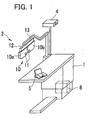
- Fig. 1 is a general view of a structure of an optometric system;
- Fig. 2 is a top view of a controller;
- Fig. 3 is a sectional view of a part of a lens chamber unit for a left eye, viewed from above;
- Fig. 4 is a schematic block view of a control system of the optometric system.
-
- A detailed description of a preferred embodiment of an optometric apparatus embodying the present invention will now be given referring to the accompanying drawings. Fig. 1 is a general view of a structure of an optometric system in the present embodiment.
- A subjective-type
optometric apparatus 2 is provided with a pair oflens chamber units 10 which are symmetrically constructed for a right and left eyes, in each of which includes atest window 11 in which various kinds of optical elements are electrically selectively disposed, and asupport unit 12 which supports (holds) thelens chamber units 10. Thesupport unit 12 is supported on a table 1 through anarm 13. It is to be noted that thelens chamber units 10 include alens chamber unit 10a for a right eye examination and alens chamber unit 10b for a left eye examination. - The optometric system is further provided with an
optotype presenting apparatus 4, acontroller 5, and arelay unit 6. The presentingapparatus 4 is used to present examination optotypes by projection. Thecontroller 5 is used to operate theoptometric apparatus 2 and the presentingapparatus 4. Therelay unit 6 is to relay transmission between the apparatuses. - Fig. 2 is a top view of the
controller 5. Thiscontroller 5 is provided with adisplay 30 and aswitch section 31. Thedisplay 30 is a liquid crystal display for displaying information or data on eye examinations and others. Theswitch section 31 includes a group ofsetting switches 32, a group ofoptotype switches 33, a group ofmask switches 34, astart switch 35, groups ofdesignation switches data input switch 39,switches dial switch 42, and a group offunction switches 45. - In the present embodiment, the
setting switches 32 are used to change a display screen of thedisplay 30 to a menu screen for setting parameters and so on. Theoptotype switches 33 are used to change (select) optotypes to be presented by the presentingapparatus 4. Themask switches 34 are used to change (select) masks to be applied to a part of the selected optotypes to be presented. Thestart switch 35 is used to execute eye examinations previously programmed. Thedesignation switches 37 are used to designate a mode for examination data and others. Thedesignation switches 38 are used to designate a data input mode or an examination mode. Thedata input switch 39 is used to input data from an objective type eye refractivepower measuring apparatus 3, alens meter 9, etc. Thedesignation switches 41 are used to designate an eye to be examined. - The
switches switch 43a causes the rotary prism to rotate in a direction that increases the prism degree, and, on the other hand, the push of theswitch 43b causes the rotary prism to rotate in the opposite direction that decreases the prism degree. Thoseswitches dial switch 42 is used to change measured values and input numeric values. Thisswitch 42 is also used to designate the prism degree in the divergence examination and the convergence examination. Thefunction switches 45 are used to select an associated one with various switch displays appear on the screen of thedisplay 30 at a predetermined lower position. - Fig. 3 is a schematic sectional view of a part of the
lens chamber unit 10b for a left eye, viewed from above. "L" is an examination optical axis. "E" is the left eye of an examinee. Thelens chamber unit 10b includes acover 100, in which six rotary disks 121-126 are placed (held) to be rotatable about ashaft 130. In each rotary disk 121-126, an opening and a plurality of optical elements are set (held). These rotary disks are arranged in the following order from nearer to farther with respect to the eye E; a high-powerspherical lens disk 121, a low-powerspherical lens disk 122, a firstauxiliary lens disk 123, a high-powercylindrical lens disk 124, a low-powercylindrical lens disk 125, and a secondauxiliary lens disk 126. Each disk 121-126 has an outer periphery formed with gear teeth and is rotated by operation of an associated one of pulse motors 111-116, thus changing an optical element to be disposed on the optical axis L. - Each disk 121-126 has at least one opening with no lens or with a lens of 0D (diopter). The
disk 121 holds elevenspherical lenses 131 of different high powers (refractive powers); -3D, -6D, -9D, -12D, -15D, -18D, +3D, +6D, +9D, +12D, and +15D. Thedisk 122 holds elevenspherical lenses 132 of different low powers (refractive powers); -0.25D, - 0.5D, -0.75D, -1D, +0.25D, +0.5D, +0.75D, +1D, +1.25D, +1.5D, and +1.75D. Thedisk 123 holdsauxiliary lenses 133 including a shielding plate (BL), a polarizing plate (P135, P45), a Maddox lens (MR), a pinhole (PH), a red/green filter (R/G), a dispersion prism (6/10Δ), a plain lens (PD) with a mark for adjustment of an interpupillary distance (the interval between the right and left lens chamber units 2) according to the examinee's pupillary distance, a spherical lens of -10D, and a spherical lens of +10D. - The
disk 124 holds fivecylindrical lenses 134 of different high powers (refractive powers); -1.5D, -3D, -4.5D, -6D, -7.5D. Thedisk 125 holds fivecylindrical lenses 135 of different low powers (refractive powers); - 0.25D, -0.5D, -0.75D, -1D, -1.25D. Thedisk 126 holds auxiliary lenses such asrotary prisms cross-cylinder lens 136c, and others. Therotary prisms cross-cylinder lens 136c are placed to be individually rotatable about the optical axis L. Therotary prisms prisms - Next, a rotation mechanism of the
rotary prisms rotary prism 136a is held in thedisk 126 through aholder 146 having gear teeth so that therotary prism 136a is rotatable about the optical axis L. The gear teeth of theholder 146 engage with asun gear 176 which is rotatable about theshaft 130. Thus, the rotation of apulse motor 181 is transmitted to therotary prism 136a through arelay gear 178 and agear 176a connected with thesun gear 176. Thepulse motor 181 is attached with agear head 182 which provides a speed reducing ratio of 1/30. Agear 183 fixed to an output shaft of thegear head 182 engages with therelay gear 178. - The
rotary prism 136b is held in thedisk 126 through aholder 147 having gear teeth, at the opposite side of therotary prism 136a (in other words, at the farther side from the eye E) so that therotary prism 136b is rotatable about the optical axis L. The gear teeth of theholder 147 engage with asun gear 177 which is rotatable about theshaft 130. Thus, the rotation of apulse motor 184 is transmitted to therotary prism 136b through arelay gear 179 and agear 177a connected with thesun gear 177. Thepulse motor 184 is attached with agear head 185 which provides a speed reducing ratio of 1/30. Agear 186 fixed to an output shaft of thegear head 185 engages with therelay gear 179. - The above gear heads 182 and 185 and the above gears constitute a rotation transmitting mechanism for transmitting the speed of rotation of the
pulse motors rotary prisms rotary prisms pulse motors 181 and 184). - It is to be noted that the
lens chamber unit 10a for a right eye examination is identical in structure to thelens chamber unit 10b for a left eye examination and hence the explanation thereof is omitted herein. - Fig. 4 is a schematic block diagram of a control system of the optometric system in the present embodiment. A switch signal from a
switch section 31 on thecontroller 5 is subjected to a predetermined processing and then inputted to amicrocomputer circuit 50. Themicrocomputer circuit 50 is connected to amemory 51 which previously stores a control program such as an eye examination program and amemory 52 which stores data on measured values in an objective refractive power examination. Themicrocomputer circuit 50 converts the switch signal to various kinds of data signals based on the control program stored in thememory 51 and controls the screen of thedisplay 30 through adisplay circuit 53. Furthermore, themicrocomputer circuit 50 transmits the converted data signals to amicrocomputer circuit 55 in therelay unit 6 and transmits data signals representing a refractive power and movements of thelens chamber unit 10 to theoptometric apparatus 2. Themicrocomputer circuit 55 transmits a data signal representing optotypes to the presentingapparatus 4. - Upon receipt of the data signal representing the refractive power, a
microcomputer circuit 60 in theoptometric apparatus 2 controls thelens chamber units lens chamber unit 10b, themicrocomputer circuit 60 drives apulse motor 111 through adrive circuit 101 to rotate thedisk 121, disposing a predetermined optical system in thetest window 11. Similarly, themicrocomputer circuit 60 drives pulsemotors 112 to 116 throughdrive circuits 102 to 106 respectively to rotate thedisks 122 to 126, disposing a predetermined optical element in thetest window 11. When receiving a data signal to change the prism degree, then, themicrocomputer circuit 60 drives thepulse motors drive circuits 107 and 108 to rotate therotary prisms lens chamber unit 10a is controlled in the same manner. - The presenting
apparatus 4, when received the data signal representing optotype(s), projects predetermined optotype(s) on a screen not shown placed forward of the eye E. - The
microcomputer circuit 55 is connected with the objective type eye refractivepower measuring apparatus 3 and thelens meter 9, and stores measurement data transmitted therefrom in amemory 56. When receiving a readout command signal from themicrocomputer circuit 50, themicrocomputer circuit 55 reads out the designated measurement data from thememory 56 and transmits it to thecontroller 5. - The operation of the optometric system constructed as above is explained below.
- The eye examination program is first executed at the push of the
start switch 35. This program, which is stored in advance in thememory 51 as mentioned above, includes previously set examination items and an examination flow. In the present embodiment, explanation is made on the operation in the divergence examination and the convergence examination after full correcting powers are prescribed for both eyes in the subjective examination using a program for the subjective eye examination. - When a ""(Divergence)

key 151 of thefunction keys 45 is pressed, therotary prisms test windows 11 for the right and left eyes respectively so that each prism base direction becomes a B.I.(Base In)/B.O.(Base Out) direction. The optotypes of minimum-sized characters which an examinee can correctly read or of slightly larger characters than the minimum-sized ones are presented in a vertical row. - In the divergence examination, when the
switch 43a is pushed, themicrocomputer circuit 50 transmits a command signal to themicrocomputer circuit 60 to start the rotation of therotary prism microcomputer circuit 60 thus causes thepulse motors switch 43a is pushed again, themicrocomputer circuit 50 transmits a command signal to themicrocomputer circuit 60 to stop the rotation of therotary prisms microcomputer circuit 60 thus causes thepulse motors switch 43b is pushed, on the other hand, themicrocomputer circuit 50 transmits a command signal to themicrocomputer circuit 60 to start the rotation of therotary prisms switch 43b is pushed again, themicrocomputer circuit 50 transmits a command signal to themicrocomputer circuit 60 to stop the rotation of therotary prisms - For rotating the
rotary prisms microcomputer circuit 60 outputs a driving pulse signal to drive thepulse motors pulse motors rotary prisms pulse motors 181 and 184) is controlled so that the prism degree is changed in steps of 0.05 prism or less; more preferably, 0.01 prism or less. For example, if the rotation transmitting mechanism is constructed such that the change step of the prism degree is 0.01 prism/pulse, thepulse motors function switch 157. At the push of thisswitch 157, the changing speed of the prism degree can be set in a range of 0.1 to 1.0 prism/sec. - The examiner pushes the
switch 43a once, starting the rotation of therotary prisms switch 43a, stopping the rotation of therotary prisms "(Blur)
key 153 of thefunction key 45 to store a value of the prism degree at that time in thememory 52. - Subsequently, the examiner pushes the
switch 43a once, further slowly continuously increasing the B.I. prism degree, and asks the examinee about whether the optotype appears double. At the time when the examinee responds that the optotype appears double, the examiner pushes theswitch 43a and pushes a ""(Break)
key 154 of thefunction key 45 to store a value of the prism degree at that time in thememory 52. - Next, the examiner pushes the
switch 43b, continuously slowly decreasing the B.I. prism degree, and asks the examinee about whether the optotype appears (has returned to) single. At the time when the examinee responds that the optotype appears single, the examiner pushes a " "(Recovery)
key 155 of thefunction key 45 to store the prism degree value at that time in thememory 52. - When a ""(Convergence)

key 152 of thefunction key 45 is pushed, therotary prisms test windows 11 for both eyes so that the prism base direction becomes the B.I./B.O. direction. In addition, the optotypes of minimum-sized characters which the examinee can correctly read or of slightly larger characters than the minimum-sized ones are presented in a vertical row. - In the convergence examination, when the
switch 43b is pushed, themicrocomputer circuit 50 transmits a command signal to themicrocomputer circuit 60 to start the rotation of therotary prisms switch 43a is pushed, on the other hand, themicrocomputer circuit 50 transmits a command signal to themicrocomputer circuit 60 to start the rotation of therotary prisms switches microcomputer circuit 50 transmits a command signal to themicrocomputer circuit 60 to stop the rotation of therotary prisms 136a and 137b. - The examiner pushes the
switch 43b once to start the rotation of therotary prisms switch 43b to stop the rotation of therotary prisms "(Blur)
key 153 of thefunction key 45 to store the prism degree at that time in thememory 52. - Subsequently, the examiner pushes the
switch 43b once, further continuously slowly increasing the B.O. prism degree, and asks the examinee about whether the optotype appears double. At the time when the examinee responds that the optotype appears double, the examiner pushes theswitch 43b again and additionally pushes the ""(Break)
key 154 of thefunction key 45 to store the prism degree in thememory 52. - Next, the examiner pushes the
switch 43a once, continuously slowly decreasing the B.O. prism degree, and asks the examinee about whether the optotype appears (has returned to) single. At the time when the examinee responds that the optotype appears single, the examiner pushes theswitch 43a and additionally pushes the ""(Recovery)
key 155 of thefunction key 45 to store the prism degree at that time in thememory 52. - The input of the command signal to start/stop the rotation of the
rotary prisms switch switch switch microcomputer circuit 60 drives thepulse motors rotary prisms - As described above, the rotation transmitting mechanism such as the gear heads 182 and 185 and others are operated to reduce the speed of rotation of the
pulse motors rotary prisms - Further, it is constructed that the
microcomputer circuit 60 drives thepulse motors - In the divergence examination and the convergence examination, it is preferable to largely change at first to some extent and then slowly change. This makes it possible to efficiently perform examinations. In particular, in the convergence examination, normally, many examinees each have about 20 prisms for both eyes. In this case, the
dial switch 42 is operated to previously designate the prism degree (for example 15 prisms) to be added to the eye E. For instance, when themicrocomputer circuit 50 transmits a signal designating the prism degree from thedial switch 42 to themicrocomputer circuit 60, themicrocomputer circuit 60 drives thepulse motors pulse motors pulse motors switches - As explained above, according to the present invention, the prism degree can be smoothly changed and the visual function examinations can be accurately conducted.
- While the presently preferred embodiment of the present invention has been shown and described, it is to be understood that this disclosure is for the purpose of illustration and that various changes and modifications may be made without departing from the scope of the invention as set forth in the appended claims.
Claims (7)
- An optometric apparatus for subjectively examining visual functions of an eye of an examinee, the apparatus including:a rotary prism (136a, 136b) disposed in front of the eye (E), for adding a prism degree to the eye (E);rotation means including a pulse motor (181, 184) and a rotation transmitting mechanism (146, 147, 176, 176a, 177, 177a, 178, 179, 182, 183, 185, 186) for transmitting rotation of the pulse motor to the rotary prism, the rotation means being adapted for rotating the rotary prism to change the prism degree;command means (43a, 43b) for generating a command signal to start and stop the rotation of the rotary prism; andcontrol means (60) for controlling the rotation means to drive the pulse motor to rotate at a speed of 5 pulses/sec. or more when the control means receives the rotation start command signal until when receives the rotation stop command signal, and, to change the prism degree at a speed of 0.1 to 1.0 prism/see.
- The optometric apparatus according to claim 1, wherein the rotation transmitting mechanism transmits the rotation of the pulse motor to the rotary prism so that a change step of the prism degree per one rotation step angle of the pulse motor is 0.05 prism or less, more preferably, 0.01 prism or less.
- The optometric apparatus according to claim 2, wherein the rotation transmitting mechanism includes a gear device (182, 185) for transmitting the rotation of the pulse motor to the rotary prism while reducing the speed of the rotation.
- The optometric apparatus according to claim 2 or 3, wherein the control means drives the pulse motor to rotate at a speed of 10 to 100 pulses/sec.
- The optometric apparatus according to one of claims 1 to 4 further including setting means (157) for setting the change speed of the prism degree in a range of 0.1 to 1.0 prism/sec.
- The optometric apparatus according to one of claims 1 to 5 further including designation means (42) for designating the prism degree to be added to the eye,
wherein the control means, when receives the designation signal from the designation means, controls the rotation means so that the prism degree changes at a speed faster than 0.1 to 1.0 prism/sec. up to the designated prism degree. - The optometric apparatus according to one of claims 1 to 6, wherein the rotary prism is a pair of prisms that have the same power and that are rotated at equal angles in opposite directions.
Applications Claiming Priority (2)
| Application Number | Priority Date | Filing Date | Title |
|---|---|---|---|
| JP2003019960 | 2003-01-29 | ||
| JP2003019960A JP2004229789A (en) | 2003-01-29 | 2003-01-29 | Optometry device |
Publications (2)
| Publication Number | Publication Date |
|---|---|
| EP1442697A1 true EP1442697A1 (en) | 2004-08-04 |
| EP1442697B1 EP1442697B1 (en) | 2006-04-05 |
Family
ID=32652863
Family Applications (1)
| Application Number | Title | Priority Date | Filing Date |
|---|---|---|---|
| EP04001827A Expired - Lifetime EP1442697B1 (en) | 2003-01-29 | 2004-01-28 | Optometric apparatus |
Country Status (5)
| Country | Link |
|---|---|
| US (1) | US7144112B2 (en) |
| EP (1) | EP1442697B1 (en) |
| JP (1) | JP2004229789A (en) |
| KR (1) | KR100960037B1 (en) |
| DE (1) | DE602004000571T2 (en) |
Cited By (3)
| Publication number | Priority date | Publication date | Assignee | Title |
|---|---|---|---|---|
| EP1762173A3 (en) * | 2005-09-02 | 2007-03-21 | Nidek Co., Ltd | Optometer |
| WO2007125955A1 (en) | 2006-04-28 | 2007-11-08 | Nidek Co., Ltd. | Vision testing system |
| EP1920710A4 (en) * | 2005-09-02 | 2009-07-01 | Nidek Kk | VIEW CONTROL APPARATUS |
Families Citing this family (7)
| Publication number | Priority date | Publication date | Assignee | Title |
|---|---|---|---|---|
| JP4794951B2 (en) * | 2005-09-02 | 2011-10-19 | 株式会社ニデック | Optometry equipment |
| US8684946B1 (en) * | 2005-12-19 | 2014-04-01 | The Uab Research Foundation | Method and apparatus for determining the sensitivity of cone photoreceptors and uses thereof |
| JP5421044B2 (en) * | 2009-09-29 | 2014-02-19 | 株式会社ニデック | Optometry equipment |
| TN2017000062A1 (en) * | 2017-02-23 | 2018-07-04 | Nadhir BOUHAOUALA | Mini Refractor. |
| CN116458834A (en) * | 2023-03-13 | 2023-07-21 | 广东机电职业技术学院 | Strabismus measurement method, prism motor subdivision setting and motion self-correction method and device |
| IT202300027741A1 (en) * | 2023-12-22 | 2025-06-22 | Centro Rham S R L | SUSTAINABLE AND MODULAR DEVICE FOR INCLUSIVE SCREENING OF POSSIBLE HEALTH PROBLEMS IN OPTICAL AND ORTHOPTICS, AND RELATED METHOD FOR 3D MODELING AND PRINTING BASED ON ARTIFICIAL INTELLIGENCE MODULES |
| FR3161546A1 (en) * | 2024-04-24 | 2025-10-31 | SiVIEW | Method, device and system for determining at least one value of fusion reserves of a subject, associated computer program |
Citations (5)
| Publication number | Priority date | Publication date | Assignee | Title |
|---|---|---|---|---|
| US3891311A (en) * | 1971-07-07 | 1975-06-24 | Nasa | Multiparameter vision testing apparatus |
| EP0070333A2 (en) * | 1981-07-22 | 1983-01-26 | BAUSCH & LOMB INCORPORATED | Motorized refractor |
| DE9005493U1 (en) * | 1990-05-15 | 1990-09-13 | J.D. Möller Optische Werke GmbH, 2000 Wedel | Device for testing visual acuity |
| EP0502413A2 (en) * | 1991-03-01 | 1992-09-09 | IMO INDUSTRIES Inc. | Scanning monochromator system |
| US6048064A (en) * | 1997-06-30 | 2000-04-11 | Nidek Co., Ltd. | Optometric apparatus |
Family Cites Families (4)
| Publication number | Priority date | Publication date | Assignee | Title |
|---|---|---|---|---|
| US4496226A (en) * | 1981-07-22 | 1985-01-29 | Bausch & Lomb Incorporated | ANDed motor control system for motorized ophthalmic instrument |
| JP2816148B2 (en) * | 1987-07-14 | 1998-10-27 | 株式会社ニコン | How to use the convergence device of the subjective eye refractive power measurement device when measuring the near point |
| JPS6420824U (en) | 1987-07-28 | 1989-02-01 | ||
| JPH08560A (en) * | 1994-06-23 | 1996-01-09 | Nikon Corp | Subjective optometer |
-
2003
- 2003-01-29 JP JP2003019960A patent/JP2004229789A/en active Pending
-
2004
- 2004-01-27 US US10/764,458 patent/US7144112B2/en not_active Expired - Lifetime
- 2004-01-27 KR KR1020040005084A patent/KR100960037B1/en not_active Expired - Fee Related
- 2004-01-28 DE DE602004000571T patent/DE602004000571T2/en not_active Expired - Lifetime
- 2004-01-28 EP EP04001827A patent/EP1442697B1/en not_active Expired - Lifetime
Patent Citations (5)
| Publication number | Priority date | Publication date | Assignee | Title |
|---|---|---|---|---|
| US3891311A (en) * | 1971-07-07 | 1975-06-24 | Nasa | Multiparameter vision testing apparatus |
| EP0070333A2 (en) * | 1981-07-22 | 1983-01-26 | BAUSCH & LOMB INCORPORATED | Motorized refractor |
| DE9005493U1 (en) * | 1990-05-15 | 1990-09-13 | J.D. Möller Optische Werke GmbH, 2000 Wedel | Device for testing visual acuity |
| EP0502413A2 (en) * | 1991-03-01 | 1992-09-09 | IMO INDUSTRIES Inc. | Scanning monochromator system |
| US6048064A (en) * | 1997-06-30 | 2000-04-11 | Nidek Co., Ltd. | Optometric apparatus |
Cited By (7)
| Publication number | Priority date | Publication date | Assignee | Title |
|---|---|---|---|---|
| EP1762173A3 (en) * | 2005-09-02 | 2007-03-21 | Nidek Co., Ltd | Optometer |
| EP1920710A4 (en) * | 2005-09-02 | 2009-07-01 | Nidek Kk | VIEW CONTROL APPARATUS |
| US7862175B2 (en) | 2005-09-02 | 2011-01-04 | Nidek Co., Ltd. | Optometer |
| US7874676B2 (en) | 2005-09-02 | 2011-01-25 | Nidek Co., Ltd. | Vision tester |
| WO2007125955A1 (en) | 2006-04-28 | 2007-11-08 | Nidek Co., Ltd. | Vision testing system |
| EP2005878A4 (en) * | 2006-04-28 | 2009-04-22 | Nidek Kk | VISUAL EXAMINATION SYSTEM |
| US7883211B2 (en) | 2006-04-28 | 2011-02-08 | Nidek Co., Ltd. | Vision testing system |
Also Published As
| Publication number | Publication date |
|---|---|
| DE602004000571T2 (en) | 2007-04-05 |
| US7144112B2 (en) | 2006-12-05 |
| KR20040070010A (en) | 2004-08-06 |
| EP1442697B1 (en) | 2006-04-05 |
| DE602004000571D1 (en) | 2006-05-18 |
| US20040184001A1 (en) | 2004-09-23 |
| KR100960037B1 (en) | 2010-06-01 |
| JP2004229789A (en) | 2004-08-19 |
Similar Documents
| Publication | Publication Date | Title |
|---|---|---|
| US3969020A (en) | Automatic refraction apparatus and method | |
| EP2005878B1 (en) | Vision testing system | |
| JP3330968B2 (en) | Subjective optometry device | |
| EP1442697B1 (en) | Optometric apparatus | |
| US7216984B2 (en) | Optometric apparatus | |
| JP3580870B2 (en) | Eye test | |
| JPH11267100A (en) | Subjective optometry device | |
| JP2585611B2 (en) | Subjective optometry device | |
| JP3672434B2 (en) | Optometry equipment | |
| JPH0910175A (en) | Optometric apparatus | |
| JP4481748B2 (en) | Optometry equipment | |
| JPS5937A (en) | Self-conscious type electromotive opthalmscope | |
| JP3602209B2 (en) | Optometry device | |
| JP2001346762A (en) | Subjective optometry device | |
| JP2903515B2 (en) | Optometry device | |
| EP0070333A2 (en) | Motorized refractor | |
| JP4413015B2 (en) | A subjective optometry device | |
| JP3468919B2 (en) | Optometry device | |
| JP2806428B2 (en) | Subjective optometry device | |
| JP3269682B2 (en) | Perimeter | |
| JP2006149843A (en) | Optometer | |
| JPH067293A (en) | Visual acuity test equipment | |
| JP2953687B2 (en) | Optometry device | |
| JPS6399835A (en) | Subjective eye refractive power measuring apparatus | |
| JPH049411B2 (en) |
Legal Events
| Date | Code | Title | Description |
|---|---|---|---|
| PUAI | Public reference made under article 153(3) epc to a published international application that has entered the european phase |
Free format text: ORIGINAL CODE: 0009012 |
|
| AK | Designated contracting states |
Kind code of ref document: A1 Designated state(s): AT BE BG CH CY CZ DE DK EE ES FI FR GB GR HU IE IT LI LU MC NL PT RO SE SI SK TR |
|
| AX | Request for extension of the european patent |
Extension state: AL LT LV MK |
|
| 17P | Request for examination filed |
Effective date: 20041227 |
|
| 17Q | First examination report despatched |
Effective date: 20050309 |
|
| AKX | Designation fees paid |
Designated state(s): DE FR GB |
|
| GRAP | Despatch of communication of intention to grant a patent |
Free format text: ORIGINAL CODE: EPIDOSNIGR1 |
|
| GRAS | Grant fee paid |
Free format text: ORIGINAL CODE: EPIDOSNIGR3 |
|
| GRAA | (expected) grant |
Free format text: ORIGINAL CODE: 0009210 |
|
| AK | Designated contracting states |
Kind code of ref document: B1 Designated state(s): DE FR GB |
|
| REG | Reference to a national code |
Ref country code: GB Ref legal event code: FG4D |
|
| REF | Corresponds to: |
Ref document number: 602004000571 Country of ref document: DE Date of ref document: 20060518 Kind code of ref document: P |
|
| ET | Fr: translation filed | ||
| PLBE | No opposition filed within time limit |
Free format text: ORIGINAL CODE: 0009261 |
|
| STAA | Information on the status of an ep patent application or granted ep patent |
Free format text: STATUS: NO OPPOSITION FILED WITHIN TIME LIMIT |
|
| 26N | No opposition filed |
Effective date: 20070108 |
|
| REG | Reference to a national code |
Ref country code: FR Ref legal event code: PLFP Year of fee payment: 12 |
|
| PGFP | Annual fee paid to national office [announced via postgrant information from national office to epo] |
Ref country code: FR Payment date: 20150108 Year of fee payment: 12 Ref country code: GB Payment date: 20150128 Year of fee payment: 12 |
|
| GBPC | Gb: european patent ceased through non-payment of renewal fee |
Effective date: 20160128 |
|
| REG | Reference to a national code |
Ref country code: FR Ref legal event code: ST Effective date: 20160930 |
|
| PG25 | Lapsed in a contracting state [announced via postgrant information from national office to epo] |
Ref country code: GB Free format text: LAPSE BECAUSE OF NON-PAYMENT OF DUE FEES Effective date: 20160128 |
|
| PG25 | Lapsed in a contracting state [announced via postgrant information from national office to epo] |
Ref country code: FR Free format text: LAPSE BECAUSE OF NON-PAYMENT OF DUE FEES Effective date: 20160201 |
|
| PGFP | Annual fee paid to national office [announced via postgrant information from national office to epo] |
Ref country code: DE Payment date: 20170125 Year of fee payment: 14 |
|
| REG | Reference to a national code |
Ref country code: DE Ref legal event code: R119 Ref document number: 602004000571 Country of ref document: DE |
|
| PG25 | Lapsed in a contracting state [announced via postgrant information from national office to epo] |
Ref country code: DE Free format text: LAPSE BECAUSE OF NON-PAYMENT OF DUE FEES Effective date: 20180801 |