EP1442281B1 - On-line optical analysis of a substance through a conduit section of a process line - Google Patents
On-line optical analysis of a substance through a conduit section of a process line Download PDFInfo
- Publication number
- EP1442281B1 EP1442281B1 EP02801264.9A EP02801264A EP1442281B1 EP 1442281 B1 EP1442281 B1 EP 1442281B1 EP 02801264 A EP02801264 A EP 02801264A EP 1442281 B1 EP1442281 B1 EP 1442281B1
- Authority
- EP
- European Patent Office
- Prior art keywords
- light
- conduit
- clip
- transmitting
- section
- Prior art date
- Legal status (The legal status is an assumption and is not a legal conclusion. Google has not performed a legal analysis and makes no representation as to the accuracy of the status listed.)
- Expired - Lifetime
Links
- 238000000034 method Methods 0.000 title claims description 48
- 230000003287 optical effect Effects 0.000 title claims description 14
- 239000000126 substance Substances 0.000 title description 18
- 238000004458 analytical method Methods 0.000 title description 6
- 239000000463 material Substances 0.000 claims description 15
- 239000000835 fiber Substances 0.000 claims description 11
- 238000010183 spectrum analysis Methods 0.000 claims description 9
- 230000002093 peripheral effect Effects 0.000 claims description 5
- 238000012545 processing Methods 0.000 description 6
- 239000000203 mixture Substances 0.000 description 4
- 239000013307 optical fiber Substances 0.000 description 4
- 238000001228 spectrum Methods 0.000 description 4
- 238000012544 monitoring process Methods 0.000 description 3
- -1 pharmaceutical Substances 0.000 description 3
- 230000000704 physical effect Effects 0.000 description 3
- 229920000642 polymer Polymers 0.000 description 3
- 229920001343 polytetrafluoroethylene Polymers 0.000 description 3
- 239000004810 polytetrafluoroethylene Substances 0.000 description 3
- 239000004215 Carbon black (E152) Substances 0.000 description 2
- 238000011109 contamination Methods 0.000 description 2
- 229930195733 hydrocarbon Natural products 0.000 description 2
- 150000002430 hydrocarbons Chemical class 0.000 description 2
- 239000004065 semiconductor Substances 0.000 description 2
- 238000004611 spectroscopical analysis Methods 0.000 description 2
- 239000004743 Polypropylene Substances 0.000 description 1
- 239000004793 Polystyrene Substances 0.000 description 1
- XAGFODPZIPBFFR-UHFFFAOYSA-N aluminium Chemical compound [Al] XAGFODPZIPBFFR-UHFFFAOYSA-N 0.000 description 1
- 229910052782 aluminium Inorganic materials 0.000 description 1
- 238000004140 cleaning Methods 0.000 description 1
- 238000005530 etching Methods 0.000 description 1
- 235000013305 food Nutrition 0.000 description 1
- 239000011521 glass Substances 0.000 description 1
- 238000009434 installation Methods 0.000 description 1
- 238000011835 investigation Methods 0.000 description 1
- 238000005259 measurement Methods 0.000 description 1
- 238000012986 modification Methods 0.000 description 1
- 230000004048 modification Effects 0.000 description 1
- 239000003208 petroleum Substances 0.000 description 1
- 229920001155 polypropylene Polymers 0.000 description 1
- 229920002223 polystyrene Polymers 0.000 description 1
- 238000002360 preparation method Methods 0.000 description 1
- 230000005855 radiation Effects 0.000 description 1
- 230000000717 retained effect Effects 0.000 description 1
- 238000012360 testing method Methods 0.000 description 1
Images

Classifications
-
- G—PHYSICS
- G01—MEASURING; TESTING
- G01N—INVESTIGATING OR ANALYSING MATERIALS BY DETERMINING THEIR CHEMICAL OR PHYSICAL PROPERTIES
- G01N21/00—Investigating or analysing materials by the use of optical means, i.e. using sub-millimetre waves, infrared, visible or ultraviolet light
- G01N21/01—Arrangements or apparatus for facilitating the optical investigation
- G01N21/03—Cuvette constructions
- G01N21/05—Flow-through cuvettes
-
- G—PHYSICS
- G01—MEASURING; TESTING
- G01N—INVESTIGATING OR ANALYSING MATERIALS BY DETERMINING THEIR CHEMICAL OR PHYSICAL PROPERTIES
- G01N21/00—Investigating or analysing materials by the use of optical means, i.e. using sub-millimetre waves, infrared, visible or ultraviolet light
- G01N21/17—Systems in which incident light is modified in accordance with the properties of the material investigated
- G01N21/25—Colour; Spectral properties, i.e. comparison of effect of material on the light at two or more different wavelengths or wavelength bands
- G01N21/251—Colorimeters; Construction thereof
- G01N21/253—Colorimeters; Construction thereof for batch operation, i.e. multisample apparatus
-
- G—PHYSICS
- G01—MEASURING; TESTING
- G01N—INVESTIGATING OR ANALYSING MATERIALS BY DETERMINING THEIR CHEMICAL OR PHYSICAL PROPERTIES
- G01N21/00—Investigating or analysing materials by the use of optical means, i.e. using sub-millimetre waves, infrared, visible or ultraviolet light
- G01N21/84—Systems specially adapted for particular applications
- G01N21/85—Investigating moving fluids or granular solids
-
- G—PHYSICS
- G02—OPTICS
- G02B—OPTICAL ELEMENTS, SYSTEMS OR APPARATUS
- G02B6/00—Light guides; Structural details of arrangements comprising light guides and other optical elements, e.g. couplings
- G02B6/10—Light guides; Structural details of arrangements comprising light guides and other optical elements, e.g. couplings of the optical waveguide type
- G02B6/102—Light guides; Structural details of arrangements comprising light guides and other optical elements, e.g. couplings of the optical waveguide type for infrared and ultraviolet radiation
-
- Y—GENERAL TAGGING OF NEW TECHNOLOGICAL DEVELOPMENTS; GENERAL TAGGING OF CROSS-SECTIONAL TECHNOLOGIES SPANNING OVER SEVERAL SECTIONS OF THE IPC; TECHNICAL SUBJECTS COVERED BY FORMER USPC CROSS-REFERENCE ART COLLECTIONS [XRACs] AND DIGESTS
- Y10—TECHNICAL SUBJECTS COVERED BY FORMER USPC
- Y10S—TECHNICAL SUBJECTS COVERED BY FORMER USPC CROSS-REFERENCE ART COLLECTIONS [XRACs] AND DIGESTS
- Y10S128/00—Surgery
- Y10S128/14—Polytetrafluoroethylene, i.e. PTFE
Definitions
- the present invention generally relates to spectroscopy and, more particularly, to a non-intrusive device for allowing spectrum analysis of a substance through a conduit section of a process line of a given processing plant.
- spectroscopy for monitoring the chemical composition and physical properties of various solutions used in processing plants, such as chemical, pharmaceutical, petroleum, semiconductors and food product processing industries.
- a spectrum analysis is performed by extracting a sample of the substance to be analyzed from the process line of the processing plant and carrying out a spectrometric analysis of the collected sample by passing near to far infrared radiation therethrough.
- Document US-A-3527542 discloses a non intrusive device suitable for allowing spectrum analysis of a confined process stream throught a light-transmitting conduit section of a process line, comprising a clip adapted to be externally mounted to the process line, said clip being at least partially made of a light-transmitting material.
- the clip includes a hollow body, and means are provided for directing a beam of light from a source of light transversally through the light-transmitting conduit section.
- this device lacks any fiber optic cable between the light source and the aforesaid conduit section.
- the light is directly received by a light-sensitive transducer, so that this known device also lacks any receiving optical fiber for receiving the light emanating from the conduit section.
- the device of document US-A-3517542 clearly does not need any optical element for focussing or directing the light into a receiving or output optical fiber.
- Document US-A-5693944 also dicloses a conduit-mounted light-transmitting device in combination with a light-transmitting conduit section of a process line for allowing optical analysis of a substance in the process line.
- the conduit-mounted light-transmitting device comprise a clip detachably securable about the conduit section, said clip having a hollow body having a conduit engaging section by which said body is releasably mounted on the light-transmitting conduit section.
- An optical element is housed whithin said body for collecting the light transmitted though the conduit section.
- the device according to document US-A-5693944 also lacks any optical element to precisely image the light exiting an optical fiber into a receiving optical fiber.
- Document WO 00/28322 discloses another conduit-mounted light-transmitting device, using fiber optic cables and an "optical element" in the form of a diffuse reflecting material serving to calibrate the device for its light reference and in absence of any conduit.
- WO 01/31318 discloses a non-intrusive device for allowing spectrum analysis of a confined process stream through a light-transmitting conduit section of a process line, comprising a clip adapted to be externally mounted to the process line, said clip being at least partly made of a light-transmitting material, said clip including a hollow body having a conduit engaging section, the conduit engaging section including an open-ended elongated peripheral slot defined in one face of the hollow body, the slot having sidewalls made of light transmitting material.
- the expression spectrum analysis is herein intended to mean the investigation of substances or bodies by means of their electromagnetic spectra, specifically chemical composition and physical properties analysis thereof.
- the expression light is herein intended to mean all wavelengths included in the electromagnetic spectrum, including the ultraviolet, visible and infrared portions of the electromagnetic spectrum.
- the present invention is generally directed to a light-transmitting device 10 adapted to be removably secured about a process line of a given processing plant to permit optical analysis of the composition and/or physical properties of a substance circulated through the process line. More specifically, the light-transmitting device 10 is adapted to be externally mounted on a conduit section of an existing process line to direct a light beam (visible, near infrared or infrared) from a remote light source (not shown), through the conduit section and then carry the light emerging from the illuminated substance through the conduit section to a light receiving sensor (not shown), such as a spectrophotometer.
- a light beam visible, near infrared or infrared
- conduit section of the process line has to be made of optically transparent or translucent material such as polytetrafluoroethylene (PTFE), other fluorinated hydrocarbon polymers, and any other light/infrared transmitting material for allowing the light to pass transversally therethrough.
- PTFE polytetrafluoroethylene
- the conduit section could be made of TeflonTM, glass, polypropylene, polystyrene or other polymers.
- the present invention advantageously allows on-line control and monitoring of a process stream without having to extract a product sample from the process line. There is thus no risk of contamination of the process stream.
- the present invention is even more advantageous in industrial applications comprising a process line including light-transmitting conduit sections in that control and monitoring of the process stream can be performed by simply installing the light-transmitting device 10 on the process line externally of a light-transmitting conduit section thereof, that is without having to replace a segment of the process line by a light-transmitting conduit section, thereby obviating any process interruption. That is to say that in those applications, the process line does not have to be modified in any way.
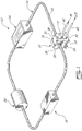
- Fig. 1 exemplifies one possible application of the present invention. More specifically, Fig. 1 depicts a wet station 12, such as those found in semiconductor industries.
- the wet station 12 essentially comprises a recirculation line 14 composed of a bath 16, a filter 18, and a pump 20 connected together in a closed circuit via TeflonTM tubing 22.
- the bath 16 can contained various solutions, such as cleaning, stripping or etching solutions.
- the light-transmitting device 10 is directly installed on a selected conduit section of the existing process line 14 externally of the TeflonTM tubing 22.
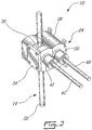
- the light-transmitting device 10 generally comprises a clip 24 adapted to be detachably secured on a variety of conduits or tubes having different external diameters.
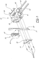
- the clip 24 has a hollow body 26 defining a peripheral open-ended elongated slot 28 adapted to receive one of a plurality of interchangeable conduit adapters, one of which is illustrated at 30 in Fig. 3 .
- a different conduit adapter is used for each diameter of conduit, thereby allowing the body 26 to be mounted on a wide variety of conduits.
- the conduit adapter 30, includes a pair of spaced-apart conduit gripping arms 32 extending perpendicularly from a base wall 33 for tightly grasping a conduit or tube having an external diameter slightly greater than the spacing between the gripping arms 32.
- At least the base wall 33 of the adapter 30 is made of a light-transmitting material, such as but not limited to PTFE or other fluorinated hydrocarbon polymers.
- the body 26 is brought over the adapter 30 to locate the same within the slot 28 in the body 26.
- the adapter 30 is retained captive in the slot 28 by a cover plate 34.
- the cover plate 34 is removably secured to the body 26 by means of screws 36.
- the cover plate 34 is provided on an undersurface thereof with an elongated locking rib 38 for engagement between a pair of axially spaced-apart locking fingers 40 extending laterally outwardly from one of the gripping arms 32 of the conduit adapter 30 to lock the latter against axial sliding movement in the slot 28.
- the body 26 is provided on one side of the slot 28 thereof with a first connector 41 for receiving the distal end portion of a first fiber optic cable 42.
- the first fiber optic cable 42 is connected at an opposed proximal end thereof to a light source (not shown) for directing a light beam, such as but not limited to an infrared beam (IR beam) or a near infrared beam (NIR beam), transversally through the conduit section of the TeflonTM tubing 22 of the process line 14.
- IR beam infrared beam
- NIR beam near infrared beam
- the sidewalls of the slot 28 can be made of a light-transmitting material for allowing the light beam to pass therethrough or, alternatively a pair of opposed aligned light-transmitting windows 44 could be formed therein.
- the windows 44 could be provided in the form of holes.
- the light beam is directed so as to perpendicularly intersect the central axis of the conduit section on which the clip 24 is mounted.
- the light that emerges from the illuminated process solution through the conduit section of the TeflonTM tubing 22, the base wall 33 of the conduit adapter 30 and one of the sidewalls of the slot 28 is diverted 180 degrees by a pair of flat mirrors 46 (see Fig. 4 ) before being transmitted to a light receiving sensor via a second fiber optic cable 48 connected at a distal end portion thereof to the body 26 of the clip 24 by a second connector 50.
- the flat mirrors 46 are mounted within the hollow body 26 of the clip 24 by means of an aluminum frame (not shown).
- An optical element, preferably a lens, is provided to focus the transmitted light into the second fiber optic cable 48.
- the second connector 50 is disposed on a side of the slot 28 opposite the first connector and in alignment therewith.
- a variety of optical elements could be integrated within the hollow body 26 of the clip 24 to cause the light to follow various optical paths between the light source and the light-receiving sensor.
- the hollow body 26 of the clip 24 is made of TeflonTM to protect the optical elements housed therein from a corrosive surrounding environment.
- TeflonTM TeflonTM to protect the optical elements housed therein from a corrosive surrounding environment.
- the clip 24 could be made out of a wide variety of materials.
- a section of such tubing could be replaced once by an appropriate conduit section, and then the light-transmitting device 10 could be used, when required, thereon, i.e. without further changes to the tubing of the process line.
- the present invention allows for on-line spectrum measurement for determining the chemical composition and/or properties of a substance through an existing conduit section in which the substance is circulated.
Landscapes
- Physics & Mathematics (AREA)
- Health & Medical Sciences (AREA)
- General Physics & Mathematics (AREA)
- General Health & Medical Sciences (AREA)
- Analytical Chemistry (AREA)
- Biochemistry (AREA)
- Chemical & Material Sciences (AREA)
- Life Sciences & Earth Sciences (AREA)
- Immunology (AREA)
- Pathology (AREA)
- Spectroscopy & Molecular Physics (AREA)
- Toxicology (AREA)
- Optics & Photonics (AREA)
- Investigating Or Analysing Materials By Optical Means (AREA)
- Optical Measuring Cells (AREA)
Description
- The present invention generally relates to spectroscopy and, more particularly, to a non-intrusive device for allowing spectrum analysis of a substance through a conduit section of a process line of a given processing plant.
- It is known to carry out spectroscopy for monitoring the chemical composition and physical properties of various solutions used in processing plants, such as chemical, pharmaceutical, petroleum, semiconductors and food product processing industries. Typically, such a spectrum analysis is performed by extracting a sample of the substance to be analyzed from the process line of the processing plant and carrying out a spectrometric analysis of the collected sample by passing near to far infrared radiation therethrough.
- Instead of the above-mentioned method, it would be preferable to perform the test on-line directly through a conduit section of the process line, and if the process line includes a conduit section made of a light-transmitting material directly through this existing conduit section, to avoid process line modifications.
- Document
US-A-3527542 discloses a non intrusive device suitable for allowing spectrum analysis of a confined process stream throught a light-transmitting conduit section of a process line, comprising a clip adapted to be externally mounted to the process line, said clip being at least partially made of a light-transmitting material. The clip includes a hollow body, and means are provided for directing a beam of light from a source of light transversally through the light-transmitting conduit section. However, this device lacks any fiber optic cable between the light source and the aforesaid conduit section. Furthermore, the light is directly received by a light-sensitive transducer, so that this known device also lacks any receiving optical fiber for receiving the light emanating from the conduit section. As such, the device of documentUS-A-3517542 clearly does not need any optical element for focussing or directing the light into a receiving or output optical fiber. - Document
US-A-5693944 also dicloses a conduit-mounted light-transmitting device in combination with a light-transmitting conduit section of a process line for allowing optical analysis of a substance in the process line. The conduit-mounted light-transmitting device comprise a clip detachably securable about the conduit section, said clip having a hollow body having a conduit engaging section by which said body is releasably mounted on the light-transmitting conduit section. An optical element is housed whithin said body for collecting the light transmitted though the conduit section. However, the device according to documentUS-A-5693944 also lacks any optical element to precisely image the light exiting an optical fiber into a receiving optical fiber. DocumentWO 00/28322 -
WO 01/31318 - It is therefore an aim of the present invention to .provide a light-transmitting device adapted to be mounted on a processing line externally of a conduit section thereof for allowing spectrum analysis of a substance circulated through the conduit section.
- It is also an aim of the present invention to provide for on-line analysis of a substance without having to extract a sample of the substance from the process line through which the substance is circulated.
- It is a further aim of the present invention to provide a light-transmitting device for allowing spectrum analysis of a substance circulated through a process line without having to modify the process line when the latter includes a conduit section made of a light-transmitting material.
- Therefore, in accordance with the present invention, there is provided a non-intrusive device according to claim 1.
- The expression spectrum analysis is herein intended to mean the investigation of substances or bodies by means of their electromagnetic spectra, specifically chemical composition and physical properties analysis thereof.
- The expression light is herein intended to mean all wavelengths included in the electromagnetic spectrum, including the ultraviolet, visible and infrared portions of the electromagnetic spectrum.
- Having thus generally described the nature of the invention reference will now be made to the accompanying drawings, showing by way of illustration a preferred embodiment thereof, and in which:
-
Fig. 1 is a schematic perspective view of a process line upon which a light-transmitting device in accordance with the present invention is externally mounted for allowing spectrum analysis of a process stream through the process line tubing; -
Fig. 2 is an enlarged view of the light-transmitting device mounted on a section of the process line; -
Fig. 3 is an enlarged partly exploded view of the light-transmitting device illustrating how the device is removably secured about a section of the process line; and -
Fig. 4 is a cross-sectional view of the light-transmitting device mounted on the process line. - The present invention, as will be explained hereinafter, is generally directed to a light-transmitting
device 10 adapted to be removably secured about a process line of a given processing plant to permit optical analysis of the composition and/or physical properties of a substance circulated through the process line. More specifically, the light-transmittingdevice 10 is adapted to be externally mounted on a conduit section of an existing process line to direct a light beam (visible, near infrared or infrared) from a remote light source (not shown), through the conduit section and then carry the light emerging from the illuminated substance through the conduit section to a light receiving sensor (not shown), such as a spectrophotometer. It is understood that the conduit section of the process line has to be made of optically transparent or translucent material such as polytetrafluoroethylene (PTFE), other fluorinated hydrocarbon polymers, and any other light/infrared transmitting material for allowing the light to pass transversally therethrough. For instance, the conduit section could be made of Teflon™, glass, polypropylene, polystyrene or other polymers. - As will be seen hereinafter the present invention advantageously allows on-line control and monitoring of a process stream without having to extract a product sample from the process line. There is thus no risk of contamination of the process stream. The present invention is even more advantageous in industrial applications comprising a process line including light-transmitting conduit sections in that control and monitoring of the process stream can be performed by simply installing the light-transmitting
device 10 on the process line externally of a light-transmitting conduit section thereof, that is without having to replace a segment of the process line by a light-transmitting conduit section, thereby obviating any process interruption. That is to say that in those applications, the process line does not have to be modified in any way. One has only to mount the light-transmittingdevice 10 externally on a light-transmitting conduit section of the process line. -
Fig. 1 exemplifies one possible application of the present invention. More specifically,Fig. 1 depicts awet station 12, such as those found in semiconductor industries. Thewet station 12 essentially comprises arecirculation line 14 composed of abath 16, afilter 18, and apump 20 connected together in a closed circuit via Teflon™tubing 22. Thebath 16 can contained various solutions, such as cleaning, stripping or etching solutions. - As seen in
Fig. 1 , the light-transmittingdevice 10 is directly installed on a selected conduit section of the existingprocess line 14 externally of the Teflon™ tubing 22. The light-transmittingdevice 10 generally comprises aclip 24 adapted to be detachably secured on a variety of conduits or tubes having different external diameters. - The
clip 24 has ahollow body 26 defining a peripheral open-endedelongated slot 28 adapted to receive one of a plurality of interchangeable conduit adapters, one of which is illustrated at 30 inFig. 3 . A different conduit adapter is used for each diameter of conduit, thereby allowing thebody 26 to be mounted on a wide variety of conduits. Theconduit adapter 30,includes a pair of spaced-apartconduit gripping arms 32 extending perpendicularly from abase wall 33 for tightly grasping a conduit or tube having an external diameter slightly greater than the spacing between the grippingarms 32. At least thebase wall 33 of theadapter 30 is made of a light-transmitting material, such as but not limited to PTFE or other fluorinated hydrocarbon polymers. Once the right adapter has been chosen and fitted over the selected conduit section of theprocess line 14, thebody 26 is brought over theadapter 30 to locate the same within theslot 28 in thebody 26. Theadapter 30 is retained captive in theslot 28 by acover plate 34. Thecover plate 34 is removably secured to thebody 26 by means ofscrews 36. Thecover plate 34 is provided on an undersurface thereof with anelongated locking rib 38 for engagement between a pair of axially spaced-apartlocking fingers 40 extending laterally outwardly from one of the grippingarms 32 of theconduit adapter 30 to lock the latter against axial sliding movement in theslot 28. - As shown in
Fig. 4 , thebody 26 is provided on one side of theslot 28 thereof with afirst connector 41 for receiving the distal end portion of a first fiberoptic cable 42. The first fiberoptic cable 42 is connected at an opposed proximal end thereof to a light source (not shown) for directing a light beam, such as but not limited to an infrared beam (IR beam) or a near infrared beam (NIR beam), transversally through the conduit section of the Teflon™ tubing 22 of theprocess line 14. The sidewalls of theslot 28 can be made of a light-transmitting material for allowing the light beam to pass therethrough or, alternatively a pair of opposed aligned light-transmittingwindows 44 could be formed therein. Thewindows 44 could be provided in the form of holes. The light beam is directed so as to perpendicularly intersect the central axis of the conduit section on which theclip 24 is mounted. - According to the illustrated embodiment of the present invention, the light that emerges from the illuminated process solution through the conduit section of the Teflon
™ tubing 22, thebase wall 33 of theconduit adapter 30 and one of the sidewalls of theslot 28 is diverted 180 degrees by a pair of flat mirrors 46 (seeFig. 4 ) before being transmitted to a light receiving sensor via a second fiberoptic cable 48 connected at a distal end portion thereof to thebody 26 of theclip 24 by asecond connector 50. According to one embodiment of the present invention, theflat mirrors 46 are mounted within thehollow body 26 of theclip 24 by means of an aluminum frame (not shown). An optical element, preferably a lens, is provided to focus the transmitted light into the second fiberoptic cable 48. Furthermore, it is noted that thesecond connector 50 is disposed on a side of theslot 28 opposite the first connector and in alignment therewith. In fact, a variety of optical elements could be integrated within thehollow body 26 of theclip 24 to cause the light to follow various optical paths between the light source and the light-receiving sensor. - According to an embodiment of the present invention, the
hollow body 26 of theclip 24 is made of Teflon™ to protect the optical elements housed therein from a corrosive surrounding environment. However, it is understood that theclip 24 could be made out of a wide variety of materials. - In the case of a
tubing 22 made of non optically transparent or translucent material, a section of such tubing could be replaced once by an appropriate conduit section, and then the light-transmittingdevice 10 could be used, when required, thereon, i.e. without further changes to the tubing of the process line. - As can be appreciated from the foregoing, the present invention allows for on-line spectrum measurement for determining the chemical composition and/or properties of a substance through an existing conduit section in which the substance is circulated.
- It is easily seen that the present invention as described above has many advantages that can be summarized as follows: no sample preparation, rapid installation with no process interruption, totally non-contact, non-intrusive for no possibility of contamination, etc.
Claims (8)
- A non-intrusive device (10) for allowing spectrum analysis of a confined process stream through a light-transmitting conduit section of a process line (14), comprising a clip (24) adapted to be externally mounted to the process line (14), said clip (24) being at least partly made of a light-transmitting material, said clip including a hollow body (26) having a conduit engaging section (28), the conduit engaging section (28) including an open-ended elongated peripheral slot (28) defined in one face of the hollow body (26), the slot (28) having sidewalls made of light transmitting material, the clip (24) being provided with a first connector (41) for receiving an input fiber optic cable (42) for directing a beam of light from a source of light transversally through the conduit section, and a second connector (50) for connecting an output fiber optic cable (48), the hollow body (26)housing at least one optical element, characterized in that the optical element focuses the light emanating from the input fiber optic cable (42) and transmitted across the conduct section into the output fiber optic cable (48) transversally through the process stream and the wall of the conduit section.
- A non-intrusive device (10) as defined in claim 1, wherein said clip (24) is adapted to be releasably secured about the light-transmitting conduit section.
- A non-intrusive device (10) as defined in claim 1, wherein said clip (24) is adjustable so as to be securable on light-transmitting conduits having different cross-sectional dimensions.
- A non-intrusive device (10) as defined in claim 1, wherein said peripheral slot (28) is adapted to receive interchangeable conduit adapters (30) adapted to grip conduits of different external diameters.
- A non-intrusive device (10) as defined in claim 4, wherein said clip (24) further includes a removable cover (34) for maintaining a selected one of said interchangeable conduit adapters (30) captive in said peripheral slot (28).
- A non-intrusive device (10) as defined in claim 1, wherein said at least one optical element comprises a lens.
- A non-intrusive device (10) as defined in claim 1, wherein said second connector (50) is connectable to a light-receiving sensor via the output fiber optic cable (48).
- A non-intrusive device (10) as defined in claim 4, wherein a conduit adapter (30) is removably installed in said open ended slot (28), said conduit adapter (30) having a base wall (33) from which extends a pair of spaced-apart conduit gripping arms (32) adapted to receive therebetween the light-transmitting conduit section, wherein said conduit adapter (30) is at least partly made of a light-transmitting material.
Applications Claiming Priority (3)
| Application Number | Priority Date | Filing Date | Title |
|---|---|---|---|
| CA2359178 | 2001-10-16 | ||
| CA 2359178 CA2359178A1 (en) | 2001-10-16 | 2001-10-16 | On-line optical analysis of a substance through a conduit section of a process line |
| PCT/CA2002/001562 WO2003034045A1 (en) | 2001-10-16 | 2002-10-16 | On-line optical analysis of a substance through a conduit section of a process line |
Publications (2)
| Publication Number | Publication Date |
|---|---|
| EP1442281A1 EP1442281A1 (en) | 2004-08-04 |
| EP1442281B1 true EP1442281B1 (en) | 2018-12-05 |
Family
ID=4170272
Family Applications (1)
| Application Number | Title | Priority Date | Filing Date |
|---|---|---|---|
| EP02801264.9A Expired - Lifetime EP1442281B1 (en) | 2001-10-16 | 2002-10-16 | On-line optical analysis of a substance through a conduit section of a process line |
Country Status (8)
| Country | Link |
|---|---|
| US (1) | US7460232B2 (en) |
| EP (1) | EP1442281B1 (en) |
| JP (1) | JP4414223B2 (en) |
| KR (1) | KR20050037416A (en) |
| CN (1) | CN100380113C (en) |
| CA (1) | CA2359178A1 (en) |
| IL (1) | IL161467A0 (en) |
| WO (1) | WO2003034045A1 (en) |
Families Citing this family (11)
| Publication number | Priority date | Publication date | Assignee | Title |
|---|---|---|---|---|
| CN100507514C (en) * | 2005-09-19 | 2009-07-01 | 中国海洋石油总公司 | High-temperature, high pressure fluid ingredient analytical sensor |
| GB2460265A (en) * | 2008-05-23 | 2009-11-25 | Univ Dublin City | Detection assembly |
| US20110201908A1 (en) * | 2010-02-17 | 2011-08-18 | Farkas Joshua D | Intermittent extracorporeal spectrophotometry |
| US9146189B2 (en) | 2014-02-28 | 2015-09-29 | Asl Analytical, Inc. | Optical cell with disposable fluid cartridge |
| GB201806797D0 (en) * | 2018-04-26 | 2018-06-13 | Res Center Pharmaceutical Engineering Gmbh | Monitoring a property of a fluid during a flow process with a flow unit and a tube being movable relative to one another |
| US10983044B2 (en) * | 2018-06-26 | 2021-04-20 | Arometrix, Inc. | Device, system and method for in-situ optical monitoring and control of extraction and purification of plant materials |
| JP7229084B2 (en) * | 2019-04-19 | 2023-02-27 | 株式会社 堀場アドバンスドテクノ | optical analyzer |
| CN112548923B (en) * | 2020-10-10 | 2022-08-23 | 中车青岛四方机车车辆股份有限公司 | Protective device |
| JP2022185655A (en) * | 2021-06-03 | 2022-12-15 | アズビル株式会社 | Optical analyzing device |
| JP2022185657A (en) * | 2021-06-03 | 2022-12-15 | アズビル株式会社 | optical analyzer |
| US12644828B2 (en) | 2024-02-15 | 2026-06-02 | Abb Schweiz Ag | Spectrometer systems and methods of remote data acquisition for detecting chemical compositions |
Citations (3)
| Publication number | Priority date | Publication date | Assignee | Title |
|---|---|---|---|---|
| US5693944A (en) * | 1994-09-02 | 1997-12-02 | Ntc Technology, Inc. | Gas analyzer cuvettes |
| WO2000028322A1 (en) * | 1998-11-06 | 2000-05-18 | Medtronic Avecor Cardiovascular, Inc. | Apparatus and method to determine blood parameters |
| WO2001031318A1 (en) * | 1999-10-22 | 2001-05-03 | Marquette University | An optical sensor for opaque and non-opaque materials |
Family Cites Families (12)
| Publication number | Priority date | Publication date | Assignee | Title |
|---|---|---|---|---|
| US3527542A (en) * | 1966-06-15 | 1970-09-08 | Beckman Instruments Inc | Cardiac output apparatus |
| FR2208527A6 (en) * | 1972-11-24 | 1974-06-21 | Perieres Jacques | |
| US3864044A (en) * | 1972-11-27 | 1975-02-04 | Combustion Equip Ass | Method and apparatus for the analysis of a dispersed phase capable of transmitting and focusing light |
| US4227814A (en) * | 1979-02-01 | 1980-10-14 | Baxter Travenol Laboratories, Inc. | Optical density detector |
| US4312341A (en) * | 1979-12-13 | 1982-01-26 | Baxter Travenol Laboratories, Inc. | Bubble detector |
| US4647210A (en) * | 1985-06-17 | 1987-03-03 | The Dow Chemical Company | Chlorine analysis using fiber optics |
| US5503805A (en) * | 1993-11-02 | 1996-04-02 | Affymax Technologies N.V. | Apparatus and method for parallel coupling reactions |
| EP0758098A1 (en) * | 1995-08-09 | 1997-02-12 | Molex Incorporated | Adapter assembly for fiber optic connectors |
| US5717209A (en) * | 1996-04-29 | 1998-02-10 | Petrometrix Ltd. | System for remote transmission of spectral information through communication optical fibers for real-time on-line hydrocarbons process analysis by near infra red spectroscopy |
| US6290912B1 (en) * | 1998-07-14 | 2001-09-18 | Bayer Corporation | Read head for luminometer |
| SE9804142D0 (en) * | 1998-11-30 | 1998-11-30 | Gambro Ab | Method and device for providing a signal |
| DE10118449C1 (en) * | 2001-04-12 | 2002-10-17 | Mwg Biotech Ag | Device for monitoring a chemical stream used in the synthesis of DNA comprises a base body having a tubular recess, light measuring paths represented by light sources and a light |
-
2001
- 2001-10-16 CA CA 2359178 patent/CA2359178A1/en not_active Abandoned
-
2002
- 2002-10-16 IL IL16146702A patent/IL161467A0/en unknown
- 2002-10-16 KR KR1020047005695A patent/KR20050037416A/en not_active Ceased
- 2002-10-16 WO PCT/CA2002/001562 patent/WO2003034045A1/en not_active Ceased
- 2002-10-16 JP JP2003536731A patent/JP4414223B2/en not_active Expired - Lifetime
- 2002-10-16 CN CNB028214803A patent/CN100380113C/en not_active Expired - Lifetime
- 2002-10-16 EP EP02801264.9A patent/EP1442281B1/en not_active Expired - Lifetime
-
2004
- 2004-04-16 US US10/825,139 patent/US7460232B2/en not_active Expired - Lifetime
Patent Citations (3)
| Publication number | Priority date | Publication date | Assignee | Title |
|---|---|---|---|---|
| US5693944A (en) * | 1994-09-02 | 1997-12-02 | Ntc Technology, Inc. | Gas analyzer cuvettes |
| WO2000028322A1 (en) * | 1998-11-06 | 2000-05-18 | Medtronic Avecor Cardiovascular, Inc. | Apparatus and method to determine blood parameters |
| WO2001031318A1 (en) * | 1999-10-22 | 2001-05-03 | Marquette University | An optical sensor for opaque and non-opaque materials |
Also Published As
| Publication number | Publication date |
|---|---|
| CA2359178A1 (en) | 2003-04-16 |
| IL161467A0 (en) | 2004-09-27 |
| US20040233453A1 (en) | 2004-11-25 |
| EP1442281A1 (en) | 2004-08-04 |
| HK1069876A1 (en) | 2005-06-03 |
| CN100380113C (en) | 2008-04-09 |
| JP2005505777A (en) | 2005-02-24 |
| KR20050037416A (en) | 2005-04-21 |
| US7460232B2 (en) | 2008-12-02 |
| CN1578904A (en) | 2005-02-09 |
| JP4414223B2 (en) | 2010-02-10 |
| WO2003034045A1 (en) | 2003-04-24 |
Similar Documents
| Publication | Publication Date | Title |
|---|---|---|
| US5407638A (en) | Detector-cell adapted for continuous-flow absorption detection | |
| US7460232B2 (en) | On-line optical analysis of a substance through a conduit section of a process line | |
| US9719917B2 (en) | Flow cell optical detection system | |
| US20040160601A1 (en) | Probe assemblies for Raman spectroscopy | |
| US5408313A (en) | Optical interface coupler and system for photometric analysis | |
| US6289149B1 (en) | Fiber optic coupled transmission cell for in-process spectrographic analysis | |
| US6028667A (en) | Compact and robust spectrograph | |
| US20080266549A1 (en) | Chemical Constituent Analyzer | |
| US9222883B2 (en) | Optical measuring system having a cell holder to accommodate flow through cells of different dimensions in the direction of optical path | |
| US20050117152A1 (en) | Optical device for simultaneous multiple measurement using polarimetry and spectrometry and method for regulating/monitoring physical-chemical and biotechnical processes using said device | |
| JP2008209160A (en) | Hollow fiber bundle | |
| CA2463851C (en) | On-line optical analysis of a substance through a conduit section of a process line | |
| JP2005505777A5 (en) | ||
| HK1069876B (en) | Non-instrusive device and conduit-mounted light-transmitting device for optical analysis | |
| KR20250006273A (en) | Compact, high-resolution, monochromatic light source for fluid sample concentration measurements | |
| JP3936935B2 (en) | Process measurement points | |
| Driver et al. | Fiber-Optic Chemical Sensing With Infrared-Transmitting Optical Fiber | |
| JP2022185655A (en) | Optical analyzing device | |
| EP4137800A1 (en) | Spatially offset raman probe with coaxial excitation and collection apertures | |
| Burger et al. | Remote spectroscopy using mid-IR fiber-coupled laboratory apparatus | |
| WO2009101418A1 (en) | Reference cell | |
| Driver et al. | Fiber-remote reflectance spectroscopy with an optimized diffuse reflectance sensor system | |
| Nikolov | Optical probe systems for miniature spectrometers | |
| LIU et al. | 8.23 Fiber-Optic Probes |
Legal Events
| Date | Code | Title | Description |
|---|---|---|---|
| PUAI | Public reference made under article 153(3) epc to a published international application that has entered the european phase |
Free format text: ORIGINAL CODE: 0009012 |
|
| 17P | Request for examination filed |
Effective date: 20040429 |
|
| AK | Designated contracting states |
Kind code of ref document: A1 Designated state(s): AT BE BG CH CY CZ DE DK EE ES FI FR GB GR IE IT LI LU MC NL PT SE SK TR |
|
| AX | Request for extension of the european patent |
Extension state: AL LT LV MK RO SI |
|
| 17Q | First examination report despatched |
Effective date: 20050524 |
|
| 17Q | First examination report despatched |
Effective date: 20050524 |
|
| GRAP | Despatch of communication of intention to grant a patent |
Free format text: ORIGINAL CODE: EPIDOSNIGR1 |
|
| STAA | Information on the status of an ep patent application or granted ep patent |
Free format text: STATUS: GRANT OF PATENT IS INTENDED |
|
| INTG | Intention to grant announced |
Effective date: 20180601 |
|
| GRAS | Grant fee paid |
Free format text: ORIGINAL CODE: EPIDOSNIGR3 |
|
| GRAA | (expected) grant |
Free format text: ORIGINAL CODE: 0009210 |
|
| GRAA | (expected) grant |
Free format text: ORIGINAL CODE: 0009210 |
|
| STAA | Information on the status of an ep patent application or granted ep patent |
Free format text: STATUS: THE PATENT HAS BEEN GRANTED |
|
| AK | Designated contracting states |
Kind code of ref document: B1 Designated state(s): AT BE BG CH CY CZ DE DK EE ES FI FR GB GR IE IT LI LU MC NL PT SE SK TR |
|
| REG | Reference to a national code |
Ref country code: GB Ref legal event code: FG4D |
|
| REG | Reference to a national code |
Ref country code: CH Ref legal event code: EP |
|
| REG | Reference to a national code |
Ref country code: AT Ref legal event code: REF Ref document number: 1073677 Country of ref document: AT Kind code of ref document: T Effective date: 20181215 |
|
| REG | Reference to a national code |
Ref country code: DE Ref legal event code: R096 Ref document number: 60249719 Country of ref document: DE |
|
| REG | Reference to a national code |
Ref country code: IE Ref legal event code: FG4D |
|
| REG | Reference to a national code |
Ref country code: NL Ref legal event code: MP Effective date: 20181205 |
|
| REG | Reference to a national code |
Ref country code: AT Ref legal event code: MK05 Ref document number: 1073677 Country of ref document: AT Kind code of ref document: T Effective date: 20181205 |
|
| PG25 | Lapsed in a contracting state [announced via postgrant information from national office to epo] |
Ref country code: ES Free format text: LAPSE BECAUSE OF FAILURE TO SUBMIT A TRANSLATION OF THE DESCRIPTION OR TO PAY THE FEE WITHIN THE PRESCRIBED TIME-LIMIT Effective date: 20181205 Ref country code: BG Free format text: LAPSE BECAUSE OF FAILURE TO SUBMIT A TRANSLATION OF THE DESCRIPTION OR TO PAY THE FEE WITHIN THE PRESCRIBED TIME-LIMIT Effective date: 20190305 Ref country code: AT Free format text: LAPSE BECAUSE OF FAILURE TO SUBMIT A TRANSLATION OF THE DESCRIPTION OR TO PAY THE FEE WITHIN THE PRESCRIBED TIME-LIMIT Effective date: 20181205 Ref country code: FI Free format text: LAPSE BECAUSE OF FAILURE TO SUBMIT A TRANSLATION OF THE DESCRIPTION OR TO PAY THE FEE WITHIN THE PRESCRIBED TIME-LIMIT Effective date: 20181205 |
|
| PG25 | Lapsed in a contracting state [announced via postgrant information from national office to epo] |
Ref country code: SE Free format text: LAPSE BECAUSE OF FAILURE TO SUBMIT A TRANSLATION OF THE DESCRIPTION OR TO PAY THE FEE WITHIN THE PRESCRIBED TIME-LIMIT Effective date: 20181205 Ref country code: GR Free format text: LAPSE BECAUSE OF FAILURE TO SUBMIT A TRANSLATION OF THE DESCRIPTION OR TO PAY THE FEE WITHIN THE PRESCRIBED TIME-LIMIT Effective date: 20190306 |
|
| PG25 | Lapsed in a contracting state [announced via postgrant information from national office to epo] |
Ref country code: NL Free format text: LAPSE BECAUSE OF FAILURE TO SUBMIT A TRANSLATION OF THE DESCRIPTION OR TO PAY THE FEE WITHIN THE PRESCRIBED TIME-LIMIT Effective date: 20181205 |
|
| PG25 | Lapsed in a contracting state [announced via postgrant information from national office to epo] |
Ref country code: CZ Free format text: LAPSE BECAUSE OF FAILURE TO SUBMIT A TRANSLATION OF THE DESCRIPTION OR TO PAY THE FEE WITHIN THE PRESCRIBED TIME-LIMIT Effective date: 20181205 Ref country code: PT Free format text: LAPSE BECAUSE OF FAILURE TO SUBMIT A TRANSLATION OF THE DESCRIPTION OR TO PAY THE FEE WITHIN THE PRESCRIBED TIME-LIMIT Effective date: 20190405 |
|
| PG25 | Lapsed in a contracting state [announced via postgrant information from national office to epo] |
Ref country code: EE Free format text: LAPSE BECAUSE OF FAILURE TO SUBMIT A TRANSLATION OF THE DESCRIPTION OR TO PAY THE FEE WITHIN THE PRESCRIBED TIME-LIMIT Effective date: 20181205 Ref country code: SK Free format text: LAPSE BECAUSE OF FAILURE TO SUBMIT A TRANSLATION OF THE DESCRIPTION OR TO PAY THE FEE WITHIN THE PRESCRIBED TIME-LIMIT Effective date: 20181205 |
|
| REG | Reference to a national code |
Ref country code: DE Ref legal event code: R097 Ref document number: 60249719 Country of ref document: DE |
|
| PLBE | No opposition filed within time limit |
Free format text: ORIGINAL CODE: 0009261 |
|
| STAA | Information on the status of an ep patent application or granted ep patent |
Free format text: STATUS: NO OPPOSITION FILED WITHIN TIME LIMIT |
|
| PG25 | Lapsed in a contracting state [announced via postgrant information from national office to epo] |
Ref country code: DK Free format text: LAPSE BECAUSE OF FAILURE TO SUBMIT A TRANSLATION OF THE DESCRIPTION OR TO PAY THE FEE WITHIN THE PRESCRIBED TIME-LIMIT Effective date: 20181205 |
|
| 26N | No opposition filed |
Effective date: 20190906 |
|
| PG25 | Lapsed in a contracting state [announced via postgrant information from national office to epo] |
Ref country code: TR Free format text: LAPSE BECAUSE OF FAILURE TO SUBMIT A TRANSLATION OF THE DESCRIPTION OR TO PAY THE FEE WITHIN THE PRESCRIBED TIME-LIMIT Effective date: 20181205 |
|
| PG25 | Lapsed in a contracting state [announced via postgrant information from national office to epo] |
Ref country code: MC Free format text: LAPSE BECAUSE OF FAILURE TO SUBMIT A TRANSLATION OF THE DESCRIPTION OR TO PAY THE FEE WITHIN THE PRESCRIBED TIME-LIMIT Effective date: 20181205 |
|
| REG | Reference to a national code |
Ref country code: CH Ref legal event code: PL |
|
| PG25 | Lapsed in a contracting state [announced via postgrant information from national office to epo] |
Ref country code: LI Free format text: LAPSE BECAUSE OF NON-PAYMENT OF DUE FEES Effective date: 20191031 Ref country code: LU Free format text: LAPSE BECAUSE OF NON-PAYMENT OF DUE FEES Effective date: 20191016 Ref country code: CH Free format text: LAPSE BECAUSE OF NON-PAYMENT OF DUE FEES Effective date: 20191031 |
|
| GBPC | Gb: european patent ceased through non-payment of renewal fee |
Effective date: 20191016 |
|
| PG25 | Lapsed in a contracting state [announced via postgrant information from national office to epo] |
Ref country code: GB Free format text: LAPSE BECAUSE OF NON-PAYMENT OF DUE FEES Effective date: 20191016 Ref country code: IE Free format text: LAPSE BECAUSE OF NON-PAYMENT OF DUE FEES Effective date: 20191016 |
|
| PG25 | Lapsed in a contracting state [announced via postgrant information from national office to epo] |
Ref country code: CY Free format text: LAPSE BECAUSE OF FAILURE TO SUBMIT A TRANSLATION OF THE DESCRIPTION OR TO PAY THE FEE WITHIN THE PRESCRIBED TIME-LIMIT Effective date: 20181205 |
|
| PGFP | Annual fee paid to national office [announced via postgrant information from national office to epo] |
Ref country code: DE Payment date: 20211020 Year of fee payment: 20 |
|
| PGFP | Annual fee paid to national office [announced via postgrant information from national office to epo] |
Ref country code: IT Payment date: 20211028 Year of fee payment: 20 Ref country code: FR Payment date: 20211021 Year of fee payment: 20 Ref country code: BE Payment date: 20211020 Year of fee payment: 20 |
|
| REG | Reference to a national code |
Ref country code: DE Ref legal event code: R071 Ref document number: 60249719 Country of ref document: DE |
|
| REG | Reference to a national code |
Ref country code: BE Ref legal event code: MK Effective date: 20221016 |