EP1442238B1 - Installation de lubrification pour boite de transmission de puissance basculante - Google Patents
Installation de lubrification pour boite de transmission de puissance basculante Download PDFInfo
- Publication number
- EP1442238B1 EP1442238B1 EP02793204A EP02793204A EP1442238B1 EP 1442238 B1 EP1442238 B1 EP 1442238B1 EP 02793204 A EP02793204 A EP 02793204A EP 02793204 A EP02793204 A EP 02793204A EP 1442238 B1 EP1442238 B1 EP 1442238B1
- Authority
- EP
- European Patent Office
- Prior art keywords
- tilting
- casing
- liquid lubricant
- axis
- radial
- Prior art date
- Legal status (The legal status is an assumption and is not a legal conclusion. Google has not performed a legal analysis and makes no representation as to the accuracy of the status listed.)
- Expired - Lifetime
Links
- 230000005540 biological transmission Effects 0.000 title claims description 50
- 238000009434 installation Methods 0.000 title claims description 38
- 230000001050 lubricating effect Effects 0.000 title claims description 21
- 238000012546 transfer Methods 0.000 claims description 63
- 239000010687 lubricating oil Substances 0.000 claims description 61
- 238000005461 lubrication Methods 0.000 claims description 53
- 239000000314 lubricant Substances 0.000 claims description 25
- 238000007789 sealing Methods 0.000 claims description 10
- 238000011144 upstream manufacturing Methods 0.000 claims description 10
- 230000005484 gravity Effects 0.000 claims description 5
- 238000004891 communication Methods 0.000 claims description 4
- 239000012528 membrane Substances 0.000 claims 1
- 230000001815 facial effect Effects 0.000 description 31
- 239000007788 liquid Substances 0.000 description 7
- 210000000056 organ Anatomy 0.000 description 4
- 230000000717 retained effect Effects 0.000 description 4
- 239000003638 chemical reducing agent Substances 0.000 description 2
- 230000000694 effects Effects 0.000 description 2
- 238000012423 maintenance Methods 0.000 description 2
- 230000014759 maintenance of location Effects 0.000 description 2
- 238000012806 monitoring device Methods 0.000 description 2
- 238000012544 monitoring process Methods 0.000 description 2
- 230000015556 catabolic process Effects 0.000 description 1
- 230000005465 channeling Effects 0.000 description 1
- 238000001816 cooling Methods 0.000 description 1
- 230000002950 deficient Effects 0.000 description 1
- 238000001514 detection method Methods 0.000 description 1
- 230000001627 detrimental effect Effects 0.000 description 1
- 235000021189 garnishes Nutrition 0.000 description 1
- 230000010354 integration Effects 0.000 description 1
- 238000004064 recycling Methods 0.000 description 1
- 238000012549 training Methods 0.000 description 1
Images



Classifications
-
- F—MECHANICAL ENGINEERING; LIGHTING; HEATING; WEAPONS; BLASTING
- F16—ENGINEERING ELEMENTS AND UNITS; GENERAL MEASURES FOR PRODUCING AND MAINTAINING EFFECTIVE FUNCTIONING OF MACHINES OR INSTALLATIONS; THERMAL INSULATION IN GENERAL
- F16H—GEARING
- F16H57/00—General details of gearing
- F16H57/04—Features relating to lubrication or cooling or heating
- F16H57/0412—Cooling or heating; Control of temperature
- F16H57/0413—Controlled cooling or heating of lubricant; Temperature control therefor
-
- B—PERFORMING OPERATIONS; TRANSPORTING
- B64—AIRCRAFT; AVIATION; COSMONAUTICS
- B64C—AEROPLANES; HELICOPTERS
- B64C27/00—Rotorcraft; Rotors peculiar thereto
- B64C27/04—Helicopters
- B64C27/12—Rotor drives
-
- F—MECHANICAL ENGINEERING; LIGHTING; HEATING; WEAPONS; BLASTING
- F16—ENGINEERING ELEMENTS AND UNITS; GENERAL MEASURES FOR PRODUCING AND MAINTAINING EFFECTIVE FUNCTIONING OF MACHINES OR INSTALLATIONS; THERMAL INSULATION IN GENERAL
- F16H—GEARING
- F16H57/00—General details of gearing
- F16H57/04—Features relating to lubrication or cooling or heating
- F16H57/0434—Features relating to lubrication or cooling or heating relating to lubrication supply, e.g. pumps; Pressure control
-
- F—MECHANICAL ENGINEERING; LIGHTING; HEATING; WEAPONS; BLASTING
- F16—ENGINEERING ELEMENTS AND UNITS; GENERAL MEASURES FOR PRODUCING AND MAINTAINING EFFECTIVE FUNCTIONING OF MACHINES OR INSTALLATIONS; THERMAL INSULATION IN GENERAL
- F16H—GEARING
- F16H57/00—General details of gearing
- F16H57/04—Features relating to lubrication or cooling or heating
- F16H57/0467—Elements of gearings to be lubricated, cooled or heated
- F16H57/0469—Bearings or seals
-
- F—MECHANICAL ENGINEERING; LIGHTING; HEATING; WEAPONS; BLASTING
- F16—ENGINEERING ELEMENTS AND UNITS; GENERAL MEASURES FOR PRODUCING AND MAINTAINING EFFECTIVE FUNCTIONING OF MACHINES OR INSTALLATIONS; THERMAL INSULATION IN GENERAL
- F16J—PISTONS; CYLINDERS; SEALINGS
- F16J15/00—Sealings
- F16J15/46—Sealings with packing ring expanded or pressed into place by fluid pressure, e.g. inflatable packings
- F16J15/48—Sealings with packing ring expanded or pressed into place by fluid pressure, e.g. inflatable packings influenced by the pressure within the member to be sealed
-
- F—MECHANICAL ENGINEERING; LIGHTING; HEATING; WEAPONS; BLASTING
- F01—MACHINES OR ENGINES IN GENERAL; ENGINE PLANTS IN GENERAL; STEAM ENGINES
- F01M—LUBRICATING OF MACHINES OR ENGINES IN GENERAL; LUBRICATING INTERNAL COMBUSTION ENGINES; CRANKCASE VENTILATING
- F01M11/00—Component parts, details or accessories, not provided for in, or of interest apart from, groups F01M1/00 - F01M9/00
- F01M11/0004—Oilsumps
- F01M2011/007—Oil pickup tube to oil pump, e.g. strainer
- F01M2011/0075—Oil pickup tube to oil pump, e.g. strainer with a plurality of tubes
Definitions
- the invention relates to a lubrication system for a box of tilting power transmission, of the type generally intended for driving in rotation at least one member driven around an axis of rotation in front of itself to be able to turn, during the rotation of the driven organ, around a tilting axis, substantially perpendicular to the axis of rotation of the driven member, the transmission box comprising a tilt-mounted casing around the tilting axis on a rigid non-tilting support.
- the tilting transmission box can be used in a non limiting, as power transmission box equipping aircraft whose propulsion system is steerable, such as dirigible balloons or aircraft of the so-called convertible type, in which case the training in rotation of the organ driven by the transmission is provided from at least one source of power in rotation, or as transmission box of power equipping wind turbines, in which case the driven member is a rotor driven in rotation by the wind, and is actually leading to the transmission that drives a receiver, for example an alternator.
- the power transmission box tilting device lubricated by the installation according to the invention can be used in all rotational propulsion systems or rotational energy generation systems which require, for their proper functioning, effective lubrication transmission members which are housed in the tilting case, such as gears, bearings, bearings and / or splines drive.
- such a transmission box can be used to the rotational drive, from at least one powertrain, by example of the turbine engine type, at least one rocking rotor of an aircraft of the convertible type, which can operate in airplane mode or in helicopter mode, and whose rotor drive shaft pivots around a tilting axis, so that it can move from one position, in which the rotor functions as an airplane propeller, for the flight in airplane mode of the aircraft, to a position in which the rotor functions as a helicopter lift rotor, for the mode in helicopter flight of the aircraft.
- a lubrication system for a box of tilting power transmission according to the preamble of claim 1 is described in the document US 2,702,168.
- a tilting power transmission box for such an aircraft convertible to tilting rotors according to the preamble of claim 16 is described in particular in FR 2 791 319 and FR 2 791 634, to which reference will be made for further details to this subject.
- each rotor, the corresponding power transmission and the corresponding motor are housed in one respectively of two articulated nacelles, each comprising a tilting front part, around the tilting axis, on a fixed rear part with respect to the aircraft, and attached to one respectively of the two wings of the aircraft, and in which are housed the corresponding engine and at least partly the whole rear gearbox of the corresponding transmission, all of which front gearbox, designed as a main gearbox helicopter, as well as the corresponding rotor shaft are housed in the tilting front of gondola, and are tilting mounted with this front part relative to the fixed rear part of the nacelle and the corresponding fixed wing.
- the object of the invention is to propose a lubrication installation according to the preamble of claim 1 for such a tilting power transmission box, and an aircraft convertible according to the preamble of claim 16, satisfying the aforementioned requirements and at the same time making it possible to volume restricts a sufficient amount of a liquid lubricant circulating non-tilting rigid support towards the tilting casing, and, in return, from last to the rigid support, through channels that integrate advantageously with the pivoting mounting means of the tilting casing on the rigid support tilting, while allowing monitoring of any leakage of lubricant at level of the interface between the rigid support and the tilting housing, and a relatively easy maintenance of the installation.
- the lubrication system for a box tilting power transmission of the type shown above, characterized in that it comprises at least one lubrication circuit under pressure of at least one member to be lubricated, such as pinion, bearing, bearing and / or splines, housed in the tilting casing, said lubrication circuit having a radial transfer bearing of liquid lubricant under pressure, between two cylindrical spans vis-à-vis, substantially coaxial around the tilting axis, and one of which is a fixed bearing, arranged on a fixed part secured to said non-tilting support, and the other is a scope pivoting piece, provided on a pivoting part integral with the pivoting housing, said radial transfer bearing comprising two annular seals of recessed U-shaped cross section with concavity of each facing towards the other and spaced from each other along the tilting axis, so as to delimit between the two seals and the two carried an annular chamber of lubricant pressurized liquid,
- This embodiment has the advantages of comprising, for each circuit of lubrication, a self-sealing radial transfer bearing, since the pressure of the liquid lubricant in the annular chamber between the two seals corresponding U ensures radial sealing by the application of the lips side of the seals against the two cylindrical spans vis-à-vis, and allow the integration of such a radial transfer bearing between a fixed part and a pivoting part that can be those at which is arranged one of the two bearings through which the tilting casing is pivotally mounted on the fixed support, or between fixed and pivoting parts of which at least one is directly attached to one respectively of a fixed part and a part pivoting at which is arranged this pivot bearing.
- At least one of the inlet and outlet ports opens into an arcuate light, centered on the tilting axis, arranged between the two seals in the fixed or pivoting range corresponding, and subtended by a corresponding center angle substantially at the pivot angle of said tilting housing.
- each of the two seals of the radial transfer bearing is retained axially between the two spans and against the pressure in said annular chamber by a radial shoulder formed on one of the two bearings or by a ring shouldered attached to one of the two spans, preferably to the fixed range.
- the installation also includes a circuit for drain, ensuring the return of the liquid lubricant from the tilting casing to the fixed part by a transfer bearing face of the liquid lubricant between two faces radial, with respect to the tilting axis, facing each other and one of which is a pivoting face formed on the pivoting part and the other is a fixed face, arranged on said fixed part, at least one emptying channel, arranged in said pivoting portion, opening into an arcuate facial light centered on the tilting axis and arranged in said radial face pivoting, facing a drain opening opening into said face radially fixed, and at the upstream end of a return duct integrated in said fixed part, to drive the liquid lubricant into a reservoir, which can to be secured to the non-tilting support, and in which liquid lubricant can taken to be returned to at least one lubrication circuit of installation, to the tilting casing.
- the corresponding facial light extends advantageously in said radial pivoting face between two other joints sealing rings, substantially coaxial about said axis of tilting and located radially one outside and the other inside said facial light, each of the other two seals having a cross-section in concavity-coated U-shape facing said fixed part, and being mounted between two substantially coaxial cylindrical bearings around the tilting axis and one of which is a pivoting seat provided on said pivoting part, and the other a fixed bearing provided on said fixed part, of so that each other seal delimits with said fixed part a annular radial sealing chamber in communication, between the two radial faces, with facial light and drain hole, and filled with liquid lubricant applying each of the two lateral lips of said other seal Sealing radially outward or inward against one respectively said pivoting or fixed cylindrical bearing surfaces.
- the installation can then advantageously comprise at least one leak detector, sensitive to a presence of liquid lubricant in a defined volume between a seal associated with the face transfer bearing of the drain circuit and a seal of the radial transfer bearing of a lubrication circuit, the two seals being mounted between the same cylindrical bearings, the detector of the possible leaks of these two seals being in particular a pressure sensor implanted with preferably in a portion of the fixed span, between these two seals.
- the emptying circuit may comprise a first drain channel, opening downstream in said facial lumen, and in upstream, in a bottom of said tilting casing in which the liquid lubricant is gravity collected in at least a first position of said rocking case around the tilting axis, and a second emptying channel, opening in said facial lumen by its downstream end and channeling lubricant liquid pressurized by at least one lubricant pressurizing member collected in at least a portion of said tilting casing, in at least one second position of the casing tilting about the tilting axis.
- the pressurizing member of the liquid lubricant collected in the tilting casing can be a pump of draining, rotated in a portion of said casing tilting in which liquid lubricant is collected in at least said second position of said casing tilting about said tilting axis, said pump draining said second drain channel.
- the pressurizing member liquid lubricant can be an Archimedean screw, the Archimedean screw being rotated in a chute extending inside and along a wall of said tilting casing, said chute being pierced with orifices for collecting liquid lubricant at different levels in said tilting casing, in at least said second position of the latter around the tilting axis, this screw Archimedes feeding the second drainage channel drain circuit of the facility clean to the invention.
- two drain pumps can be driven into the tilting casing, in which these two pumps are arranged so that each pump liquid lubricant collected in one respectively two portions of the tilting casing, when the latter occupies one or the other respectively the two extreme positions of tipping around the tilting axis.
- the installation according to the invention advantageously comprises two lubrication circuits, of which one circuit main and an emergency circuit, such as their radial transfer bearings, substantially the same radius around the tilting axis, are offset relative to each other along the axis of tilting, and in the direction circumferential around the tilting axis with respect to their inlet and outlet openings and, where appropriate, their arc-shaped and the emptying of the liquid lubricant is ensured by a draining circuit common to both lubrication circuits.
- one circuit main and an emergency circuit such as their radial transfer bearings, substantially the same radius around the tilting axis, are offset relative to each other along the axis of tilting, and in the direction circumferential around the tilting axis with respect to their inlet and outlet openings and, where appropriate, their arc-shaped and the emptying of the liquid lubricant is ensured by a draining circuit common to both lubrication circuits.
- the installation may further include less a leak detector, sensitive to a presence of liquid lubricant in the volume delimited between the radial transfer bearings of the two lubrication, when these radial transfer bearings are axially offset between the same fixed and pivoting cylindrical scopes, which is advantageously the case, since it makes it possible to use the same fixed and pivoting for both lubrication circuits, and therefore also the only drain.
- An independent lubrication system is thus produced by so that the supply duct or ducts, integrated (s) in the fixed part of or for each of the lubrication circuits, is or are fed from a liquid lubricant reservoir in which at least one pump is immersed of lubrication for each lubrication circuit.
- each lubrication pump is driven by a pinion of a first reducer assembly housed at least partly in a non-tilting casing secured to said support, said first gear unit being engaged by a pinion mounted in rotation about said tilting axis, with a second gear unit housed in said tilting and pivoting casing with this latest.
- each lubrication circuit comprises, in the latter, at least one annular channel of distribution, substantially centered on said axis of rotation of the driven member, and connected to said annular chamber of the corresponding radial transfer bearing by said distribution line.
- This annular distribution channel is advantageously arranged in a diaphragm substantially transverse to said tilting and supporting casing at least one guide bearing of at least one shaft of at least one pinion of the second reduction unit and / or of said rotated member, each annular distribution channel supplying liquid lubricant lubrication ending in lubricant jets directed towards lubricating in said tilting housing.
- the invention also relates to a convertible aircraft, comprising at minus a tilting rotor intended to be rotated about an axis of rotation, in front of itself to pivot about a tilting axis, by at minus one tilting power transmission box, comprising a casing mounted tilting about said tilting axis, which is substantially perpendicular to said axis of rotation, on at least one non-rocking rigid support integral with the structure of said aircraft, said housing housing at least a member to be lubricated, such as pinions, bearings, bearings and / or splines, the aircraft being characterized in that it comprises at least one installation of lubricating said at least one power transmission box tilting device, and in that said lubrication system is an installation according to the invention, as defined above.
- the lateral module 5 Downstream of the high speed reduction stage of the input module 1, the lateral module 5 comprises a first intermediate reduction stage constituted a pinion 6, driven by the output shaft of the freewheel 4, and engaged with a pinion 7 itself engaged in a second intermediate reduction stage, with a pinion 8 said "tilting" because rotated with his shaft 9 about the tilting axis B-B of a gear unit tipping of the transmission described below.
- the tilting pinion 8 is also engaged with a pinion intermediate 10 itself engaged with a pinion 11 of interconnection with the interconnection shaft, partially shown at 12, for driving in rotation of another rotor from the engine M, when the engine drive of the other rotor is out of order, or for the drive of the rotor R from the drive motor of the other rotor, when the motor M is in breakdown.
- the cylindrical gear train 6, 7, 8, 10 and 11 of the lateral module 5 constitutes a lateral gear train with respect to the output shaft of the engine M, and this lateral module 5 constitutes with the input module 1 a set non-tilting gearbox of the transmission, arranged in a transmission box intermediate, connected by the shaft 9 of the tilting pinion 8 to a set gearbox of the transmission, now described.
- This tilting reducer assembly arranged like a box of main helicopter transmission, includes a main module 13 consisting of an input reduction stage, of the conical torque type or spiroconic, of which a conical input gear 14 is coaxial with the pinion cylindrical tilt 8 and rotationally fixed to this pinion of tilting, in at least one direction of rotation, about the axis of tilting B-B.
- the main module 13 is a failover module with conical or spiroconic torque, also having a conical wheel toothed output 15, in engagement with the bevel gear 14, and whose shaft 16 is guided in rotation about the axis A-A of rotation of the rotor R, and integral in rotation of a planet gear 18, a reducing output stage of the type epicyclic or epicyclic module 17, the planetary gear 18 is in taken with planet gears 19, also in engagement with a crown toothed external device 20, retained in rotation in the bottom of a housing tilting, as explained below, the planet gears 19 being mounted in rotation each around its axis, on the shafts of a planet carrier 21 integral in coaxial rotation of the mast 22 of the rotor R about the axis of rotation A-A.
- the front tilting gearbox consisting of the main modules 13 and epicyclic 17, is housed in a tilting casing 23, consisting of a bottom housing 24 assembled to a casing top 25 of convergent profiled shape to the rotor R.
- the base of the rotor mast 22 is mounted and guided in rotation at the top 25 by a roller bearing 26 and a bearing 27 double row of tapered rollers, and is rotated by splines axial engagement with axial splines in a central bore of the planet carrier 21 which, as shown in FIGS. 6 and 7, is housed and mounted in rotation with the rest of the power transmission box 13-17, in the housing bottom 24, in which the shaft 16 common to the planetary gear 18 and the conical wheel 15 is mounted and guided in rotation by a ball bearing 28 and two roller bearings 29 ( Figure 1).
- the tilting casing 23 is pivotally mounted by its housing base 24, around the tilting axis B-B (axis of the bevel gear 14, pinion of tilting 8 and its shaft 9) on a non-tilting rigid support 30 ( Figures 4 and 5), attached to the structure of the rear part of a driving pod corresponding to the structure of a fixed wing of the convertible aircraft, as described in the aforementioned patents.
- This pivoting mounting of the housing 23 on the support 30 is provided by the journalling assembly of the housing base 24 between two fixed pieces of pivot 31, secured to the support 30, by two plain bearings, one of which is described below with reference to Figures 8 and 9.
- the gears of the lateral module 5 of the non-tilting gear unit are housed in a lateral non-tilting casing 32, also integral with the fixed part 31 and the rigid support 30, and represented in FIGS. 6 and 7, also showing the arrangement of certain elements of the epicyclic module 17 in the housing bottom 24, in which is particularly retained the crown external tooth 20.
- non-tilting casing 32 of the lateral module 5 is not shown in Figure 1, in which only the tilting pinion 8 and its tree 9, belonging to this module, are presented schematically, as well that the fixed part 31 traversed by this shaft 9, at the level of the bearing of corresponding pivoting.
- non-tilting lateral casing 32 also supports accessories driven by module sprockets lateral 5, in particular a hydraulic pump 33 driven by the pinion intermediate 10, and two lubrication pumps 34a and 34b belonging to the lubrication system described below, and driven from the pinion interconnection 11 while the intermediate gear 7 drives the shaft of a cooling fan of a heat exchanger of the installation of lubrication, and that an alternator 35 is driven by the shaft of the conical wheel 3 of the input module 1.
- This pressure lubrication system is necessary to lubricate the 13-17 tilting power transmission box housed in the crankcase tilting 23, and in particular the gears and gears of the basic module 13 and the epicyclic module 17 and their bearings and bearings 26 to 29, and the splines for driving the rotor mast 22 by the planet carrier 21.
- This lubrication system schematically represented on the FIG. 1 comprises a lateral reservoir 36 of liquid lubricant, integral with the support 30 and the non-tilting lateral casing 32, and in which are housed the two lubrication pumps 34a and 34b, one of which 34a (FIG. of a main lubrication circuit 37a, while the other pump of 34b lubrication is that of a relief lubrication circuit 37b.
- Each lubrication pump 34a, 34b is for example of the pumped gear type liquid lubricant in the bottom of the reservoir 36, through a filter 38a or 38b, being bi-passed through a pressure relief valve 39a or 39b, for supplying a conduit 40a or 40b.
- the conduit 40a supply circuit main 37a opens into a filter 41 at the inlet of a heat exchanger 42 swept by a stream of air moved by a fan 43, driven by rotation by the intermediate gear 7 of the lateral module 5, to cool the liquid lubricant of the main circuit 37a.
- the inlet of exchanger 42 is connected to its output by a bypass line equipped with a calibrated valve 44, for the cold start of the installation, and the main conduit 40a splits, after the output of the heat exchanger 42, in two branches, one of which is a 45a of alternator lubrication conduit 35, and the other a conduit 46a which is at least partially integrated in the fixed part 31 secured to the support 30, and feeds a bearing 47a liquid transfer lubricant under pressure of the fixed part 31 inside the tilting casing 23.
- the supply duct 40b of the emergency circuit 37b does not pass by the filter 41 and the heat exchanger 42, and is also subdivided into two branches, including a conduit 45b lubricating backup of the alternator 35, and a conduit 46b partially integrated in the fixed part 31 and feeding a second bearing 47b liquid transfer lubricant under pressure of the part fixed from the installation to the inside of the tilting case 23.
- the lubrication circuit main 37a or emergency 37b is extended by a distribution line 48a or 48b opening, inside the tilting casing 23, in a channel annular distribution 49a or 49b, surrounding the shaft 16 and substantially centered on the axis of rotation A-A of the rotor mast 22, each annular channel of distribution 49a and 49b supplying liquid lubricant main 50a or 50b relief lubrication ending with jets of main lubricant 51a or emergency 51b which are directed to the organs to lubricate such as the gears and pinions of the basic module 13 and the epicyclic module 17, as well as to the bearings 26 to 29.
- the distribution channel 49b of the backup circuit 37b feeds a number of lubrication lines 50b, and thus jets of relief lubrication 51b, lower than the number of lubrication 50a and lubricating jets 51a of the main circuit 37a, because the circuit 37b, the liquid lubricant of which is not cooled in the exchanger 42, provides emergency lubrication only at critical points in the tilting casing 23, in the event of failure of the main circuit 37a.
- the two main circuits 37a and 37b backup normally operate in permanently, their lubrication pumps 34a and 34b being normally permanently trained.
- the liquid lubricant flows by gravity, in particular along the inner walls of the casing 23, and collection in the lower part of the housing 23, which is the housing bottom 24 when the casing 23, and therefore the tilting power transmission box, is in helicopter mode, or which is the lowest part of the sump 24 and the upper case 25 when the entire housing 23 is switched to airplane mode ( Figure 5), in which case the liquid lubricant is collected and pressurized by a pump or screw Archimedes, as described below, to be driven under pressure in a portion of the housing bottom 24, at a channel of drain 53 of a single drain circuit 52, ensuring the return of the lubricant liquid from the rocking housing 23 to the tank 36, through the fixed part 31, thanks to a transfer bearing 54, between the casing 23 and the fixed part 31, which is in communication with a return line 55 integrated in the part fixed 31 and opening into the reservoir 36.
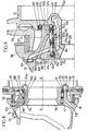
- the transfer bearings 47a and 47b of the main lubrication circuits 37a and 37b have the same structure and are arranged between portions opposite two cylindrical bearing surfaces 56 and 57, coaxial around the tilting axis B-B and vis-à-vis, one of which 56 is a fixed range arranged on the fixed part 31 and turned radially outwards, being positioned radially inside the other cylindrical bearing surface 57, defined by a bore in a pivoting portion 58 which is integral in rotation with the Tilting casing 23.
- the fixed part 31 and the swivel part 58 are respectively integral with a sleeve 59 and a pin 60 (see FIGS.
- Each transfer bearing 47a or 47b of pressurized lubricant comprises two seals 62a and 63a, or 62b and 63b (see FIGS. 9a, 9b, 9c) which are annular and each with a recessed U-shaped cross-section, and arranged between the staves 56 and 57 so that each of the two joints of the same bearing 47a or 47b is open towards the other seal, that is to say that the concavity of each of the seals 62a, 63a or 62b, 63b of each level of transfer 47a or 47b is turned towards the other seal of the same bearing.
- Both seals 62a, 63a or 62b, 63b are spaced from each other in the direction of the tilting axis B-B, and delimit between them and between the litters 56 and 57 an annular chamber 64a or 64b of liquid lubricant under pressure, the pressure has the effect of applying each of the two lateral lips of each seal 62a, 63a, or 62b, 63b, radially inward or outwardly outside, that is to say towards range 56 or range 57, and against the corresponding scope or, possibly, any body fitting that range 56 or 57.
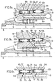
- Such a member may be a shoulder ring such as 65 (see FIG. 9a and 9b), which is fixed to one of the two bearing surfaces 56 and 57, for example to the fixed bearing 56, in order to axially retain a seal, such as 62a, against the pressure in the corresponding annular chamber, such as 64a, which tends to separate the two seals such as 62a and 63a from each other, the other seal such as 63a of the same transfer stage as 47a being also retained axially, either by another shouldered ring, or by at least one radial shoulder such as 66 or 67, arranged on one of the spans 56 and 57, as shown in Figures 9a and 9b for example.
- Another organ that can garnish one of the litters 56 and 57, and against which one of the side lips of a seal can be applied from sealing manner by the pressure in the annular chamber 64a, 64b corresponding, is a ring such as 68a or 68b, in FIG. the portion of the fixed bearing surface 56 which extends between the two seals 62a and 63a or 62b and 63b, and in which a light 69a or 69b has been machined into arc-centered, centered on the B-B tilting axis and subtended by an arc in the center of about 110 ° corresponding substantially to the maximum angle of pivoting of the tilting casing 23 on the non-tilting support 30.
- each of these lights 69a and 69b which are offset with respect to the other not only according to the tilting axis B-B but also in the direction circumferential circumference about the tilting axis B-B, as shown in FIG. 12, opens an inlet port 70a or 70b, pierced in the fixed range 56 between the two seals 52a, 53a or 52b, 53b, and whereby the light 69a or 69b and the corresponding annular chamber 64a or 64b are fed with liquid lubricant through the downstream end of the supply duct 46a or 46b integrated in the fixed part 31.
- Each annular chamber 64a or 64b thus fed with lubricant pressurized liquid, in turn supplies the tilting case 23 with lubricant liquid under pressure through an outlet 71a or 71b, which opens into the pivoting surface 57, between the two seals 62a, 63a or 62b, 63b of the same transfer bearing 47a or 47b, and at the upstream end of the corresponding distribution 48a or 48b, which extends in the pivoting part 58.
- this distribution line 48a or 48b opens into the corresponding annular distribution channel 49a or 49b, these two channels being for example formed in the base of a diaphragm 72, substantially transverse inside the rocking case 23, and supporting, in its annular central part, at least one bearing, such as one of the bearings 29 for guiding the shaft 16 of the bevel gear 15 and the pinion sun gear 18 of the second gear unit 13-17, or another bearing guiding for example the rotor mast 22.
- cylindrical rings having arc-shaped lights such as rings 68a, 68b with light 69a, 69b, may be provided, instead of or in addition to the latter, against the pivoting surface 57 and such that the outlet orifice 71a or 71b opens into their light, which is always opposite, whatever the position of tilting casing 23, an inlet port 70a or 70b lead directly into fixed range 56.
- rings such 68a, 68b with an arcuate light such as 69a or 69b ensures a transfer rate of lubricant under pressure which is sufficient whatever the position of the tilting housing 23.
- the fixed part 31 which is an annular piece (see FIGS. 12 and 13) presents a central bore traversed by the input bevel gear 14 of the basic module 13, which pinion 14 is mounted and guided in rotation in the fixed part 31 by ball bearings 73 and rollers 74.
- FIG. 9c shows that a leak detector 75, such as a sensor of pressure, can be implanted in the portion of the fixed span 56 which extends between the seal 47a of the transfer bearing 47a and the seal 62b of the other transfer bearing 47b, which joints 63a and 62b delimit with the corresponding portions of the fixed and pivoting spans 57 57 a volume 76 in which are collected the possible leakage rates of these two seals 63a and 62b, and to which the pressure sensor 75 is sensitive.
- a leak detector 75 such as a sensor of pressure
- This detector 75 can be integrated into a monitoring circuit, and can detect Leakage of pressurized liquid lubricant between the two radial transfer seals 47a and 47b, but without being able to identify which of the two seals corresponding 63a or 62b which leaks, when one of the two is defective.
- the single drain circuit 52 (at the bottom of FIG. 8), its transfer bearing 54 of lubricant from tilting casing 23 to conduit 55 of back to the reservoir 36, is a transfer bearing facial between two faces radial members 77 and 78 (relative to the tilting axis B-B) which are substantially coaxial annular around the tilting axis B-B and in vis-à-vis, one being a pivoting radial face 77 formed on the part pivoting 58, and the other being a fixed radial face 78 formed on the fixed part 31 (see Figures 10, 11 and 11a).
- FIG. 11a The schematic representation of Figure 11a shows that a light facial 79, arc-centered centered on the tilting axis B-B and extending on an angular sector of about 110 ° corresponding to the maximum angle of tilting casing 23, is formed in the radial face pivoting 77 and supplied with liquid lubricant collected in the housing bottom 24 as described below.
- This facial light 79 is always, whatever the position of the tilting casing 23, in front of a drain port 80 formed in the fixed radial face 78 at the upstream end of the return duct 55 integrated in the fixed part 31 and leading to the reservoir 36.
- This emptying orifice 80 is of a section of passage greater than that of the inlet orifices 70a, 70b or outlet 71a, 71 b of the radial transfer bearings 47a, 47b to facilitate flow at a sufficient speed of the recycled liquid lubricant to the reservoir 36, and to not create significant loss of load.
- the facial transfer bearing 54 has a radial seal provided by two other annular seals 81 and 82, coaxial around the tilting axis B-B and of the same nature as the joints sealing radial transfer bearings 47a and 47b, that is to say of section transverse U-shaped.
- One 81 of these two joints extends radially to the inside of the facial lumen 79, and the other seal 82 extends radially to outside of this facial lumen 79.
- Each of the joints 81 and 82 is disposed so that its concavity is turned towards the fixed part 31, and the joint 81 is mounted between two portions radially facing each other of the two fixed and swivel coaxial cylindrical bearing surfaces 57, between which are mounted the seals 62a, 63a, and 62b, 63b of each of the two radial transfer bearings 47a and 47b.
- the other gasket 82 in radial position external, is mounted between two cylindrical bearing surfaces 83 and 84, substantially coaxial about the tilting axis B-B, and one of which is a range pivoting on the pivoting part 58 and limiting the radial face swiveling 77 radially outward, while the other cylindrical scope 83 is a fixed surface formed on the fixed part 31.
- each seal 81 and 82 delimits with the fixed part 31 an annular chamber 85 or 86 radial sealing, which is in communication with the facial light 79 and the emptying orifice 80 by the axial clearance between the two radial faces 77 and 78, so that every chamber 85 or 86 is filled with liquid lubricant under enough pressure to apply each of the two lateral lips of each of the seals 81 and 82 radially outwardly or inwardly against one respectively fixed cylindrical bearing surfaces 56 or 83 or pivoting 57 or 84.
- a leak detector 90 of the sensor type of pressure as the leak detector 75 of Figure 9c, can be implanted in the portion of the fixed span 56 which extends between these two seals 81 and 63b, this detector 90 being sensitive to the presence of liquid lubricant under pressure in the volume 91 delimited between these two joints.
- the detector of leakage can be implanted in 90 'in the portion of the pivoted port 57 defining this volume 91 on the pivoting part 58.
- the facial lumen 79 of the facial transfer bearing 54 is in fact fed by one and / or the other two drain channels 53a and 53b, each of which is effective in one respectively of the two extreme positions of crankcase tilting tilting 23 relative to the fixed support 30.
- the lubricant having been projected onto lubricated members in the tilting housing 23 is collected by gravity, as represented in FIG. 10, in a collecting tank 92 carried by the party swivel 58 in the housing bottom 24, and the lubricant flows by gravity and through the drain channel 53a drilled in the pivoting portion 58 to lead into the facial lumen 79, and therefore between the two radial faces 77 and 78 of this facial transfer bearing 54.
- the liquid lubricant collected in the less a lower zone of the casing 23 is pressurized, by a setting member pressure can be a drain pump, driven in rotation in the housing bottom 24 from one of the pinions or toothed wheels of the transmission which is housed in this housing 23, for example a pinion auxiliary gear engaged with the gear wheel 15 and whose shaft drives directly or indirectly this drain pump.
- the liquid lubricant collected and pressurized in the case bottom 24 is then driven into the facial light 79 by a second emptying channel 53b formed in the pivoting piece 58, as schematically shown in FIG.
- two drain pumps can be driven into the housing bottom 24, and arranged so that one takes lubricant when the tilting casing 23 is in airplane mode, and the other when the casing 23 is in helicopter mode.
- This or these pump (s) drain can or can transfer the lubricant collected in the case bottom 24 at the face transfer stage 54 by an appropriate number of drain channels such as 53a and 53b.
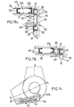
- the device for pressurizing the lubricant collected in the bottom of casing 24 in airplane mode is preferably, as proposed in the patent aforementioned French, an Archimedean screw, as schematically represented in Figure 14, substantially corresponding to Figure 1 of this patent French.
- This screw Archimedes 93 is rotated, by a take of movement on one of the pinions or toothed wheel in the tilting casing 23, in a trough 94 which extends inside and along the wall of the housing 23, and in particular which appears protruding outwardly from the housing base 24, in a direction contained in a plane passing through the axis of rotation A-A, and in the lowest part of the crankcase 24 when the crankcase 23 is switched to airplane mode.
- This trough 94 partially projecting towards the outside of the case bottom 24 is shown in FIGS. 4, 6 and 7 also.
- this chute 94 communicates, through different orifices 95, arranged at different levels along the length of the trough 94, with inside the housing 23, in order to collect the liquid lubricant flowing in the casing 23 tilted.
- This collected lubricant is displaced by the Archimedes screw 93, under sufficient pressure, until the entrance to the second drain channel 53b, in a transfer zone for supplying the facial light 79 and the facial transfer seal 54 in liquid lubricant recovered in the casing 23 in airplane mode.
Landscapes
- Engineering & Computer Science (AREA)
- General Engineering & Computer Science (AREA)
- Mechanical Engineering (AREA)
- Physics & Mathematics (AREA)
- Architecture (AREA)
- Fluid Mechanics (AREA)
- Aviation & Aerospace Engineering (AREA)
- General Details Of Gearings (AREA)
Description
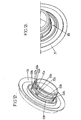
- la figure 1 illustre schématiquement une transmission de puissance avec carter basculant et installation de lubrification associée, pour un rotor basculant d'aéronef convertible,
- les figures 2 et 3 sont des vues schématiques en perspective de la transmission représentée sans carter,
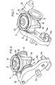
- les figures 4 et 5 sont des vues en perspective de la transmission représentée avec le carter basculant respectivement en mode hélicoptère et en mode avion,
- les figures 6 et 7 sont des vues en perspective de la transmission des figures 4 et 5 sans la partie supérieure du carter en mode hélicoptère, et le mât rotor ainsi que certains éléments de transmission qui y sont logés,
- la figure 8 est une vue schématique, en coupe par l'axe de basculement, dans la zone d'un palier de pivotement du carter et des circuits de lubrification et de vidange de l'installation de la figure 1,
- la figure 9 est une vue à plus grande échelle d'un détail de la figure 8 au niveau d'un palier de pivotement du carter et des paliers de transfert radial des circuits de lubrification,
- les figures 9a et 9b sont des représentations schématiques de variantes de la figure 9 limitées au circuit de lubrification principal respectivement de secours,
- la figure 9c illustre schématiquement un dispositif de surveillance à détection de fuite entre les paliers de transfert radial des deux circuits de lubrification,
- les figures 10 et 11 sont des vues analogues à la figure 9 de détails de la figure 8 au niveau du même palier de pivotement du carter et du palier de transfert facial du circuit de vidange, dans les positions de basculement du carter correspondant aux modes respectivement hélicoptère et avion du rotor entraíné par la transmission,
- la figure 11a est une représentation schématique d'une variante du palier de transfert facial des figures 10 et 11,
- la figure 11b illustre schématiquement un détecteur de fuite du dispositif de surveillance, entre le palier de transfert facial du circuit de vidange et le palier de transfert radial d'un circuit de lubrification,
- les figures 12 et 13 sont des vues en perspective de la partie fixe dans laquelle sont partiellement aménagés les paliers de transfert radial et facial de l'installation de lubrification, et
- la figure 14 est une vue schématique du carter basculé en mode avion avec une vis d'Archimède du circuit de vidange de l'installation de lubrification.
Claims (16)
- Installation de lubrification pour une boíte de transmission de puissance basculante (13-17), destinée à entraíner en rotation au moins un organe mené (22) autour d'un axe de rotation (A-A) devant lui-même pivoter autour d'un axe de basculement (B-B), sensiblement perpendiculaire audit axe de rotation (A-A) dudit organe mené (22), tel qu'un rotor basculant d'aéronef convertible ou de ballon dirigeable, ladite boíte de transmission comprenant un carter (23) monté basculant autour dudit axe de basculement (B-B) sur un support rigide non basculant (30),
caractérisée en ce qu'elle comprend au moins un circuit de lubrification (37a, 37b) sous pression pour la lubrification d'au moins un organe à lubrifier, tel que pignon, palier, roulement et/ou cannelures, logé dans le carter basculant (23), ledit circuit de lubrification comportant un palier de transfert radial (47a, 47b) de lubrifiant liquide sous pression, entre deux portées cylindriques (56, 57) en vis-à-vis, sensiblement coaxiales autour de l'axe de basculement (B-B), et dont l'une est une portée fixe (56), ménagée sur une partie fixe (31), ladite partie fixe pouvant être rendue solidaire dudit support non basculant (30), et l'autre est une portée pivotante (57), ménagée sur une partie pivotante (58), ladite partie pivotante pouvant être rendue solidaire du carter pivotant (23), ledit palier de transfert radial (47a, 47b) comportant deux joints d'étanchéité annulaires (62a, 63a ; 62b, 63b) de section transversale en U couché, à concavité de chacun tournée vers l'autre et espacés l'un de l'autre selon l'axe de basculement (B-B), de sorte à délimiter entre les deux joints (62a, 63a ; 62b, 63b) et les deux portées (56, 57) une chambre annulaire (64a, 64b) de lubrifiant liquide sous pression, dont la pression applique chacune des deux lèvres latérales de chaque joint d'étanchéité radialement vers l'intérieur ou l'extérieur vers et/ou contre l'une respectivement des deux portées (56, 57), ladite chambre annulaire (64a, 64b), d'une part, étant alimentée en lubrifiant liquide sous pression par un orifice d'entrée (70a, 70b), débouchant dans la portée fixe (56) entre les deux joints d'étanchéité (62a, 63a ; 62b, 63b), et à l'extrémité aval d'au moins un conduit d'alimentation (46a, 46b) intégré dans ladite partie fixe (31) et dont l'extrémité amont est reliée à au moins une source (34a, 34b) de lubrifiant pressurisé, et, d'autre part, étant capable d'alimenter le carter basculant (23) en lubrifiant liquide sous pression par un orifice de sortie (71 a, 71 b), débouchant dans la portée pivotante (57) entre les deux joints d'étanchéité (62a, 63a ; 62b, 63b), et à l'extrémité amont d'au moins une conduite de distribution (48a, 48b) s'étendant dans la partie pivotante (58) et apte à déboucher dans le carter basculant (23). - Installation selon la revendication 1, caractérisée en ce que l'un au moins des orifices d'entrée (70a, 70b) et de sortie (71 a, 71 b) débouche dans une lumière (69a, 69b) en arc-de-cercle, centrée sur l'axe de basculement (B-B), ménagée entre les deux joints d'étanchéité (62a, 63a ; 62b, 63b) dans la portée fixe (56) ou pivotante (57) correspondante, et sous-tendue par un angle au centre correspondant sensiblement à l'angle de pivotement dudit carter basculant (23).
- Installation selon l'une quelconque des revendications 1 et 2, caractérisée en ce que chacun des deux joints d'étanchéité (62a, 63a ; 62b, 63b) du palier de transfert radial (47a, 47b) est retenu axialement entre les deux portées (56, 57) et contre la pression dans ladite chambre annulaire (64a, 64b) par un épaulement radial (66, 67) ménagé sur l'une des deux portées (56, 57) ou par une bague épaulée (65) fixée à l'une des deux portées (56, 57), de préférence à la portée fixe (56).
- Installation selon l'une quelconque des revendications 1 à 3, caractérisée en ce qu'elle comprend également un circuit de vidange (52), assurant le retour du lubrifiant liquide du carter basculant (23) dans la pièce fixe (31) par un palier de transfert facial (54) du lubrifiant liquide entre deux faces radiales (77, 78), par rapport à l'axe de basculement (B-B), en vis-à-vis et dont l'une est une face pivotante (77) ménagée sur la partie pivotante (58) et l'autre est une face fixe (78), ménagée sur ladite partie fixe (31 ), au moins un canal de vidange (53a, 53b), ménagé dans ladite partie pivotante (58), débouchant dans une lumière faciale (79) en arc-de-cercle centrée sur l'axe de basculement (B-B) et ménagée dans ladite face radiale pivotante (77), en regard d'un orifice de vidange (80) débouchant dans ladite face radiale fixe (78), et à l'extrémité amont d'un conduit de retour (55) intégré dans ladite partie fixe (31 ), pour conduire le lubrifiant liquide dans un réservoir (36).
- Installation selon la revendication 4, caractérisée en ce que ladite lumière faciale (79) s'étend dans ladite face radiale pivotante (77) entre deux autres joints d'étanchéité annulaires (81, 82), sensiblement coaxiaux autour dudit axe de basculement (B-B) et situés radialement l'un (82) à l'extérieur et l'autre (81) à l'intérieur de ladite lumière faciale (79), chacun des deux autres joints d'étanchéité (81, 82) ayant une section transversale en U couché à concavité tournée vers ladite pièce fixe (31 ), et étant monté entre deux portées cylindriques (56, 57 ; 83, 84) sensiblement coaxiales autour de l'axe de basculement (B-B) et dont l'une est une portée pivotante (57, 84) ménagée sur ladite pièce pivotante (58), et l'autre une portée fixe (56, 83) ménagée sur ladite pièce fixe (31), de sorte que chaque autre joint d'étanchéité (81, 82) délimite avec ladite pièce fixe (31) une chambre annulaire (85, 86) d'étanchéité radiale en communication, entre les deux faces radiales (77, 78), avec la lumière faciale (79) et l'orifice de vidange (80), et remplie de lubrifiant liquide appliquant chacune des deux lèvres latérales dudit autre joint d'étanchéité (81, 82) radialement vers l'extérieur ou l'intérieur contre l'une respectivement desdites portées cylindriques fixe (56, 83) ou pivotante (57, 84).
- Installation selon la revendication 5, caractérisée en ce qu'elle comporte au moins un détecteur de fuite (90, 90'), sensible à une présence de lubrifiant liquide dans un volume (91) délimité entre un joint d'étanchéité (81) associé au palier de transfert facial (54) et un joint d'étanchéité (63b) du palier de transfert radial (47b) d'un circuit de lubrification (27b), les deux joints d'étanchéité (81, 63b) étant montés entre les mêmes portées cylindriques (56, 57).
- Installation selon l'une quelconque des revendications 4 à 6, caractérisée en ce que le circuit de vidange (52) comprend un premier canal de vidange (53a), débouchant en aval dans ladite lumière faciale (79), et, en amont, dans un fond (24) dudit carter basculant (23) dans lequel le lubrifiant liquide est collecté par gravité dans au moins une première position dudit carter basculant (23) autour de l'axe de basculement (B-B), et un deuxième canal de vidange (53b), débouchant dans ladite lumière faciale (79) par son extrémité aval et canalisant du lubrifiant liquide pressurisé par au moins un organe (93) de mise en pression du lubrifiant collecté dans au moins une partie dudit carter basculant (23), dans au moins une deuxième position du carter basculant (23) autour de l'axe de basculement (B-B).
- Installation selon la revendication 7, caractérisée en ce que ledit organe (93) de mise en pression dudit lubrifiant liquide collecté dans ledit carter basculant (23) est une pompe de vidange, entraínée en rotation dans une partie dudit carter basculant (23) dans laquelle du lubrifiant liquide est collecté dans au moins ladite deuxième position dudit carter basculant (23) autour dudit axe de basculement (B-B), ladite pompe de vidange alimentant ledit second canal de vidange (53b).
- Installation selon la revendication 7, caractérisée en ce que ledit organe de mise en pression du lubrifiant liquide est une vis d'Archimède (93), entraínée en rotation dans une goulotte (94) s'étendant à l'intérieur et le long d'une paroi dudit carter basculant (23), ladite goulotte (94) étant percée d'orifices (95) de collecte du lubrifiant liquide à différents niveaux dans ledit carter basculant (23), dans au moins ladite deuxième position de ce dernier autour de l'axe de basculement (B-B), ladite vis d'Archimède (93) alimentant ledit second canal de vidange (53b).
- Installation selon l'une quelconque des revendications 1 à 9 précédentes, caractérisée en ce qu'elle comprend deux circuits de lubrification, dont un circuit principal (37a) et un circuit de secours (37b), tels que leurs paliers de transfert radial (47a, 47b), sensiblement de même rayon autour de l'axe de basculement (B-B), sont décalés l'un par rapport à l'autre selon l'axe de basculement (B-B) et en direction circonférentielle autour de l'axe de basculement (B-B) pour ce qui concerne leurs orifices d'entrée (70a, 70b) et de sortie (71 a, 71 b) et, le cas échéant, leur lumière en arc-de-cercle (69a, 69b), et en ce que la vidange (52) du lubrifiant liquide est assurée par un circuit de vidange commun aux deux circuits de lubrification (37a, 37b).
- Installation selon la revendication 10, caractérisée en ce qu'elle comporte au moins un détecteur de fuite (75), sensible à une présence de lubrifiant liquide (47a, 47b) dans le volume délimité entre les paliers de transfert radial des deux circuits de lubrification (37a, 37b), lesdits paliers de transfert radial (47a, 47b) étant axialement décalés entre les mêmes portées cylindriques fixe (56) et pivotante (57).
- Installation selon l'une quelconque des revendications 10 et 11, caractérisée en ce que ledit au moins un conduit d'alimentation (46a, 46b), intégré dans ladite partie fixe (31 ) de chacun des circuits de lubrification (37a, 37b), est alimenté à partir d'un réservoir (36) de lubrifiant liquide dans lequel est immergée au moins une pompe de lubrification (34a, 34b) pour chaque circuit de lubrification (37a, 37b).
- Installation selon la revendication 12, caractérisée en ce que chaque pompe de lubrification (34a, 34b) est entraínée par un pignon (11) d'un premier ensemble réducteur (1-5) logé au moins en partie dans un carter non basculant (32) solidaire dudit support (30), ledit premier ensemble réducteur (1-5) étant en prise, par un pignon (8) monté en rotation autour dudit axe de basculement (B-B), avec un second ensemble réducteur (13-17) logé dans ledit carter basculant (23) et pivotant avec ce dernier.
- Installation selon l'une quelconque des revendications 1 à 13, caractérisée en ce que, dans ledit carter basculant (23), chaque circuit de lubrification (37a, 37b) comporte au moins un canal annulaire de distribution (49a, 49b), sensiblement centré sur ledit axe de rotation (A-A) de l'organe mené (22), et relié à ladite chambre annulaire (64a, 64b) du palier de transfert radial (47a, 47b) correspondant par ladite conduite de distribution (48a, 48b).
- Installation selon la revendication 14, caractérisée en ce que ledit canal annulaire de distribution (49a, 49b) est ménagé dans un diaphragme (72) sensiblement transversal audit carter basculant (23) et supportant au moins un roulement de guidage (29) d'au moins un arbre (16) d'au moins un pignon (15, 18) du second ensemble réducteur (13-17) et/ou dudit organe mené (22) en rotation, chaque canal annulaire de distribution (49a, 49b) alimentant en lubrifiant liquide des conduites de lubrification (50a, 50b) se terminant par des jets de lubrifiant (51 a, 51 b) orientés vers des organes à lubrifier (14, 15, 16, 18, 19, 20, 21, 25-29) dans ledit carter basculant (23).
- Aéronef convertible, comprenant au moins un rotor basculant (R) destiné à être entraíné en rotation autour d'un axe de rotation (A-A), devant lui-même pivoter autour d'un axe de basculement (B-B), par au moins une boíte de transmission de puissance basculante (13-17), comprenant un carter (23) monté basculant autour dudit axe de basculement (B-B), qui est sensiblement perpendiculaire audit axe de rotation (A-A), sur au moins un support rigide non-basculant (30) solidaire de la structure dudit aéronef, ledit carter (23) logeant au moins un organe à lubrifier, tel que pignons, paliers, roulements et/ou cannelures, caractérisé en ce qu'il comporte au moins une installation de lubrification de ladite au moins une boíte de transmission de puissance basculante, et en ce que ladite installation de lubrification est une installation selon l'une quelconque des revendications 1 à 15.
Applications Claiming Priority (3)
| Application Number | Priority Date | Filing Date | Title |
|---|---|---|---|
| FR0114392A FR2831938B1 (fr) | 2001-11-07 | 2001-11-07 | Installation de lubrification pour boite de transmission de puissance basculante |
| FR0114392 | 2001-11-07 | ||
| PCT/FR2002/003757 WO2003040593A1 (fr) | 2001-11-07 | 2002-10-31 | Installation de lubrification pour boite de transmission de puissance basculante |
Publications (2)
| Publication Number | Publication Date |
|---|---|
| EP1442238A1 EP1442238A1 (fr) | 2004-08-04 |
| EP1442238B1 true EP1442238B1 (fr) | 2005-05-04 |
Family
ID=8869141
Family Applications (1)
| Application Number | Title | Priority Date | Filing Date |
|---|---|---|---|
| EP02793204A Expired - Lifetime EP1442238B1 (fr) | 2001-11-07 | 2002-10-31 | Installation de lubrification pour boite de transmission de puissance basculante |
Country Status (5)
| Country | Link |
|---|---|
| US (1) | US7137590B2 (fr) |
| EP (1) | EP1442238B1 (fr) |
| DE (1) | DE60204041T2 (fr) |
| FR (1) | FR2831938B1 (fr) |
| WO (1) | WO2003040593A1 (fr) |
Families Citing this family (36)
| Publication number | Priority date | Publication date | Assignee | Title |
|---|---|---|---|---|
| FR2831938B1 (fr) * | 2001-11-07 | 2004-02-20 | Eurocopter France | Installation de lubrification pour boite de transmission de puissance basculante |
| FR2842271B1 (fr) | 2002-07-15 | 2004-09-10 | Eurocopter France | Boite de transmissiion de puissance basculante a transfert de charge par le carter |
| EP1685025B1 (fr) * | 2003-11-21 | 2007-07-04 | Airbus | Systeme de refroidissement d'un aeronef et aeronef equipe d'un tel systeme |
| DE102007004965B4 (de) * | 2007-01-26 | 2012-05-16 | Sew-Eurodrive Gmbh & Co. Kg | Getriebe mit Ölkreislauf-Verrohrung und Getriebe-Baureihe |
| US8794107B2 (en) | 2010-05-05 | 2014-08-05 | Hamilton Sundstrand Corporation | Submerged gear and bearing guard |
| DE102010033228A1 (de) * | 2010-08-03 | 2012-02-09 | Siemens Aktiengesellschaft | Vorrichtung zur Sprühschmierung eines Windturbinengetriebes |
| US8915465B1 (en) * | 2010-09-09 | 2014-12-23 | Groen Brothers Aviation, Inc. | Mast main bearing lubrication and thermal management |
| US8973863B1 (en) | 2010-09-09 | 2015-03-10 | Groen Brothers Aviation, Inc. | Blade root attachment apparatus and method |
| US9260186B1 (en) * | 2010-09-09 | 2016-02-16 | Groen Brothers Aviation, Inc. | Oil lubricated swashplate |
| FR2969577B1 (fr) | 2010-12-22 | 2012-12-21 | Eurocopter France | Aeronef muni d'un rotor arriere basculant, et procede associe |
| EP2712805B1 (fr) * | 2012-09-28 | 2016-03-02 | AGUSTAWESTLAND S.p.A. | Système et procédé de refroidissement d'une transmission d'aéronef capable d'effectuer du vol stationnaire |
| EP2724934B1 (fr) * | 2012-10-26 | 2016-09-21 | AGUSTAWESTLAND S.p.A. | Aéronef capable d'effectuer du vol stationnaire |
| US9156545B1 (en) | 2013-05-22 | 2015-10-13 | Bell Helicopter Textron Inc. | Folding of rotorcraft rotor blades |
| FR3008679B1 (fr) | 2013-07-16 | 2015-08-14 | Eurocopter France | Installation motrice modulaire et aeronef muni d'un rotor de sustentation |
| EP3194791B1 (fr) * | 2014-07-31 | 2020-01-08 | Sikorsky Aircraft Corporation | Ensemble de refroidissement d'huile de boîte de vitesses |
| FR3027992B1 (fr) * | 2014-10-31 | 2016-12-09 | Airbus Helicopters | Dispositif de lubrification a fiabilite augmentee a triple circuit d'une boite de transmission principale de puissance d'un aeronef |
| JP5894252B1 (ja) * | 2014-12-22 | 2016-03-23 | エアバス ヘリコプターズ | モジュール式動力装置、及び揚力ロータを備えた航空機 |
| CN105882956B (zh) * | 2014-12-24 | 2018-03-02 | 空客直升机 | 模块化动力设备以及设有升力旋翼的飞行器 |
| US20170138461A1 (en) | 2015-08-12 | 2017-05-18 | Sikorsky Aircraft Corporation | Lubrication systems |
| US10655728B2 (en) | 2015-12-01 | 2020-05-19 | The Boeing Company | Reconfigurable lubrication system for tiltrotor transmission |
| US10302523B2 (en) | 2016-05-27 | 2019-05-28 | Pratt & Whitney Canada Corp. | Method for testing a seal of a sealed bearing cavity |
| EP3484765A4 (fr) | 2016-07-12 | 2020-03-18 | Sikorsky Aircraft Corporation | Système et procédé de détection d'un état de sortie de lubrifiant dans une boîte de transmission d'aéronef |
| US10344846B2 (en) * | 2016-09-23 | 2019-07-09 | Bell Helicopter Textron Inc. | Fan mounted on gearshaft |
| US10428928B2 (en) * | 2017-03-24 | 2019-10-01 | Hamilton Sundstrand Corporation | Lubrication system for high speed gearbox operating in zero gravity |
| JP6846301B2 (ja) * | 2017-06-27 | 2021-03-24 | 川崎重工業株式会社 | ヘリコプタ用の動力伝達装置 |
| FR3074558B1 (fr) * | 2017-12-05 | 2020-01-10 | Airbus Helicopters | Systeme fluidique pour lubrifier et/ou refroidir un ensemble mecanique |
| US10844948B2 (en) * | 2017-12-08 | 2020-11-24 | Airbus Helicopters | Lubrication device having a plurality of lubrication liquid recovery tanks, and optimized and reliable delivery means to a main tank |
| US11313455B2 (en) * | 2018-10-05 | 2022-04-26 | Textron Innovations Inc. | Aircraft gearbox lubrication system with multiple lubrication subsystems |
| CN109573062B (zh) * | 2018-11-28 | 2021-07-27 | 中国航发湖南动力机械研究所 | 分布式螺旋桨推动系统、控制方法及飞行器 |
| JP7052746B2 (ja) * | 2019-01-25 | 2022-04-12 | トヨタ自動車株式会社 | 車両用動力伝達装置 |
| DE102019208860B3 (de) * | 2019-06-18 | 2020-06-25 | Magna powertrain gmbh & co kg | Schmiermittelverbrauchersystem für ein Kraftfahrzeug |
| EP3895984B1 (fr) * | 2019-12-27 | 2023-02-15 | Leonardo S.p.a. | Aéronef apte à effectuer un vol stationnaire |
| FR3112835B1 (fr) * | 2020-07-21 | 2022-06-24 | Airbus Helicopters | Procédé de surveillance d’un système fluidique lubrifiant un système mécanique |
| US11549443B2 (en) | 2020-08-28 | 2023-01-10 | Pratt & Whitney Canada Corp. | Sealing arrangement with vent for an engine component with a service port |
| CN112196981A (zh) * | 2020-09-25 | 2021-01-08 | 中国直升机设计研究所 | 一种防外泄滑油系统 |
| FR3159215B1 (fr) * | 2024-02-13 | 2026-03-06 | Airbus Helicopters | Système mécanique muni d’éléments mécaniques mobiles, d’un bouchon magnétique ainsi que d’un système de lubrification muni de filtres mécanique et magnétique. |
Citations (1)
| Publication number | Priority date | Publication date | Assignee | Title |
|---|---|---|---|---|
| US2702168A (en) * | 1950-07-07 | 1955-02-15 | Haviland H Platt | Convertible aircraft |
Family Cites Families (32)
| Publication number | Priority date | Publication date | Assignee | Title |
|---|---|---|---|---|
| US1443572A (en) * | 1921-04-25 | 1923-01-30 | George W Gosline | Propelling mechanism for airplanes |
| US1868975A (en) * | 1930-11-14 | 1932-07-26 | Charles S Hall | Propeller drive mechanism |
| US2273129A (en) * | 1939-06-07 | 1942-02-17 | Messinger William | Bearing seal |
| US2731282A (en) * | 1953-02-04 | 1956-01-17 | Walworth Co | Shaft seal |
| US3075690A (en) * | 1960-04-18 | 1963-01-29 | Emerson Electric Mfg Co | Enclosed transmission mechanism |
| FR1544378A (fr) * | 1966-11-30 | 1968-10-31 | Chicago Pneumatic Tool Co | Compresseur centrifuge de fluides gazeux |
| US3424372A (en) | 1966-11-30 | 1969-01-28 | Chicago Pneumatic Tool Co | Centrifugal gaseous medium compressor |
| US3528630A (en) * | 1968-03-20 | 1970-09-15 | United Aircraft Corp | Pitch and fold mechanism for a tiltable rotor usable in an aircraft capable of helicopter and propeller modes of operation |
| DE2411693A1 (de) * | 1974-03-12 | 1975-09-18 | Kloeckner Humboldt Deutz Ag | Einrichtung zur vermeidung von schmiermittelverlusten bei schnellaufenden zahnradgetrieben |
| US3995793A (en) * | 1974-07-25 | 1976-12-07 | Wing Russell T | Roto-wing jet airplane |
| US3942387A (en) * | 1974-10-15 | 1976-03-09 | United Technologies Corporation | Replaceable freewheel unit for helicopters |
| JPS6032331Y2 (ja) * | 1981-06-05 | 1985-09-27 | 株式会社クボタ | バ−チカルエンジンの羽根車式潤滑装置 |
| US4571157A (en) * | 1981-10-02 | 1986-02-18 | Karl Eickmann | Propeller with an interior arrangement to variate the pitch |
| US4766859A (en) * | 1987-07-24 | 1988-08-30 | Yamaha Hatsudoki Kabushiki Kaisha | Lubricating system for vertical shaft engine |
| US4858426A (en) * | 1988-07-21 | 1989-08-22 | General Motors Corporation | Secondary oil system for gas turbine engine |
| US4856273A (en) * | 1988-07-21 | 1989-08-15 | General Motors Corporation | Secondary oil system for gas turbine engine |
| SE464830B (sv) * | 1989-10-19 | 1991-06-17 | Volvo Ab | Anordning foer smoerjning av kugghjul |
| FR2658577A1 (fr) * | 1990-02-20 | 1991-08-23 | Aerospatiale | Dispositif de lubrification de secours pour reducteur notamment pour boite de transmission principale de giravion. |
| US5239880A (en) * | 1992-09-21 | 1993-08-31 | General Motors Corporation | Load sharing right angle bevel gear drive |
| DE4422987C2 (de) * | 1994-06-30 | 1996-07-18 | Wilmowsky Freiherr Von Kaspar | Kipprotorhubschrauber |
| US5788372A (en) * | 1996-05-10 | 1998-08-04 | Lord Corporation | Method and apparatus for reducing transient motion between an aircraft power member and structure during takeoff, landing and maneuvers |
| DE19700182A1 (de) * | 1997-01-04 | 1998-07-09 | Industrieanlagen Betriebsges | Luftfahrzeug mit einem im wesentlichen als aerostatischem Auftriebskörper ausgebildeten Rumpf |
| CN1268997A (zh) * | 1997-07-08 | 2000-10-04 | 赖哈特研究及发展有限公司 | 内燃机的改进和有关内燃机的改进 |
| FR2791634B1 (fr) * | 1999-03-30 | 2001-06-15 | Eurocopter France | Perfectionnements aux aeronefs convertibles a rotors basculants |
| US6227481B1 (en) * | 1999-08-06 | 2001-05-08 | Bell Helicopter Textron, Inc. | Method and apparatus for controlling force fights in a rotating shaft |
| US6247667B1 (en) * | 1999-08-06 | 2001-06-19 | Bell Helicopter Textron Inc. | Tiltrotor aircraft pylon conversion system |
| FR2814522B1 (fr) * | 2000-09-25 | 2002-12-13 | Eurocopter France | Dispositif de lubrification d'une boite de transmission de puissance presentant une orientation variable, en particulier pour un aeronef convertible a rotors basculants |
| ITTO20010101A1 (it) * | 2001-02-02 | 2002-08-02 | Agusta Spa | Rotore con gruppo di trasmissione omocinetico per un aeromobile. |
| FR2830307B1 (fr) * | 2001-10-02 | 2003-12-05 | Eurocopter France | Boite de transmission de puissance basculante a roues a denture frontale peripherique de type "far gear" |
| FR2831934B1 (fr) * | 2001-11-06 | 2004-01-16 | Eurocopter France | Boite de transmission basculante avec dispositif de rattrapage de jeu selon l'axe de basculement |
| FR2831938B1 (fr) * | 2001-11-07 | 2004-02-20 | Eurocopter France | Installation de lubrification pour boite de transmission de puissance basculante |
| FR2842271B1 (fr) * | 2002-07-15 | 2004-09-10 | Eurocopter France | Boite de transmissiion de puissance basculante a transfert de charge par le carter |
-
2001
- 2001-11-07 FR FR0114392A patent/FR2831938B1/fr not_active Expired - Fee Related
-
2002
- 2002-10-31 EP EP02793204A patent/EP1442238B1/fr not_active Expired - Lifetime
- 2002-10-31 WO PCT/FR2002/003757 patent/WO2003040593A1/fr not_active Ceased
- 2002-10-31 US US10/494,767 patent/US7137590B2/en not_active Expired - Lifetime
- 2002-10-31 DE DE60204041T patent/DE60204041T2/de not_active Expired - Lifetime
Patent Citations (1)
| Publication number | Priority date | Publication date | Assignee | Title |
|---|---|---|---|---|
| US2702168A (en) * | 1950-07-07 | 1955-02-15 | Haviland H Platt | Convertible aircraft |
Also Published As
| Publication number | Publication date |
|---|---|
| DE60204041T2 (de) | 2006-03-16 |
| US7137590B2 (en) | 2006-11-21 |
| FR2831938B1 (fr) | 2004-02-20 |
| WO2003040593A1 (fr) | 2003-05-15 |
| FR2831938A1 (fr) | 2003-05-09 |
| US20050115770A1 (en) | 2005-06-02 |
| DE60204041D1 (de) | 2005-06-09 |
| EP1442238A1 (fr) | 2004-08-04 |
Similar Documents
| Publication | Publication Date | Title |
|---|---|---|
| EP1442238A1 (fr) | Installation de lubrification pour boite de transmission de puissance basculante | |
| CA2949818C (fr) | Boite d'engrenages de turbomachine d'aeronef | |
| CA2751521C (fr) | Lubrification et refroidissement d'un reducteur a train d'engrenages epicycloidal | |
| CA2938385C (fr) | Turbomachine equipee d'un groupe de lubrification | |
| CA2874707C (fr) | Palier a moyen de lubrification et systeme pour changer le pas des pales d'une helice de turbopropulseur d'aeronef, equipe dudit palier | |
| EP3956555B1 (fr) | Reducteur de vitesse d'une turbomachine | |
| EP0540406A1 (fr) | Système de sauvegarde d'un ensemble mécanique multiplicateur/réducteur, en particulier du type "boîte de transmission" d'hélicoptère, en cas de perte d'huile de lubrification | |
| FR3087233A1 (fr) | Module de soufflante a pales a calage variable | |
| EP3857029B1 (fr) | Reservoir auxiliaire d'huile pour une turbomachine d'aeronef | |
| FR3014478A1 (fr) | Assemblage pour turbomachine d'aeronef comprenant un dispositif de circulation de fluide a conception amelioree vis-a-vis des risques de fuite | |
| EP4187128A1 (fr) | Collecteur de liquide de lubrification pour maneton d'un train epicycloïdal d'engrenages, boite de transmission de puissance et aeronef | |
| EP4073371A1 (fr) | Système propulsif aéronautique à faible débit de fuite et rendement propulsif amélioré | |
| FR2831934A1 (fr) | Boite de transmission basculante avec dispositif de rattrapage de jeu selon l'axe de basculement | |
| EP3610177B1 (fr) | Train d'engrenages epicycloïdal | |
| CA3084918A1 (fr) | Boite de transmission de puissance, giravion equipe d'une telle boite de transmission et methode de variation associee | |
| EP3610175B1 (fr) | Lubrification pour train d'engrenages épicycloïdal | |
| EP4073354B1 (fr) | Pressurisation d'enceintes de lubrification dans une turbomachine a turbine contrarotative | |
| EP3896311B1 (fr) | Dispositif de transfert d'huile | |
| EP3964734A1 (fr) | Dispositif de separation et de collecte de deux flux d'un liquide de lubrification, train epicycloïdal d'engrenages, boite de transmission de puissance et aeronef | |
| FR3147585A1 (fr) | Lubrification de paliers dans une turbomachine d’aéronef | |
| FR3156828A1 (fr) | Ensemble pour une turbomachine d’aeronef comprenant un reducteur et un systeme de lubrification du reducteur | |
| FR3104205A1 (fr) | Pressurisation d’enceintes de lubrification dans une turbomachine a turbine contrarotative |
Legal Events
| Date | Code | Title | Description |
|---|---|---|---|
| PUAI | Public reference made under article 153(3) epc to a published international application that has entered the european phase |
Free format text: ORIGINAL CODE: 0009012 |
|
| 17P | Request for examination filed |
Effective date: 20040421 |
|
| AK | Designated contracting states |
Kind code of ref document: A1 Designated state(s): AT BE BG CH CY CZ DE DK EE ES FI FR GB GR IE IT LI LU MC NL PT SE SK TR |
|
| AX | Request for extension of the european patent |
Extension state: AL LT LV MK RO SI |
|
| GRAP | Despatch of communication of intention to grant a patent |
Free format text: ORIGINAL CODE: EPIDOSNIGR1 |
|
| GRAS | Grant fee paid |
Free format text: ORIGINAL CODE: EPIDOSNIGR3 |
|
| GRAA | (expected) grant |
Free format text: ORIGINAL CODE: 0009210 |
|
| AK | Designated contracting states |
Kind code of ref document: B1 Designated state(s): DE FR GB IT |
|
| REG | Reference to a national code |
Ref country code: GB Ref legal event code: FG4D Free format text: NOT ENGLISH |
|
| REG | Reference to a national code |
Ref country code: IE Ref legal event code: FG4D Free format text: LANGUAGE OF EP DOCUMENT: FRENCH |
|
| REF | Corresponds to: |
Ref document number: 60204041 Country of ref document: DE Date of ref document: 20050609 Kind code of ref document: P |
|
| GBT | Gb: translation of ep patent filed (gb section 77(6)(a)/1977) |
Effective date: 20050907 |
|
| PLBE | No opposition filed within time limit |
Free format text: ORIGINAL CODE: 0009261 |
|
| STAA | Information on the status of an ep patent application or granted ep patent |
Free format text: STATUS: NO OPPOSITION FILED WITHIN TIME LIMIT |
|
| RAP2 | Party data changed (patent owner data changed or rights of a patent transferred) |
Owner name: AVIO S.P.A. Owner name: EUROCOPTER |
|
| 26N | No opposition filed |
Effective date: 20060207 |
|
| REG | Reference to a national code |
Ref country code: GB Ref legal event code: 732E |
|
| REG | Reference to a national code |
Ref country code: GB Ref legal event code: 732E |
|
| REG | Reference to a national code |
Ref country code: FR Ref legal event code: CD Ref country code: FR Ref legal event code: TQ |
|
| REG | Reference to a national code |
Ref country code: DE Ref legal event code: R082 Ref document number: 60204041 Country of ref document: DE Representative=s name: BEETZ & PARTNER PATENT- UND RECHTSANWAELTE, DE |
|
| REG | Reference to a national code |
Ref country code: DE Ref legal event code: R082 Ref document number: 60204041 Country of ref document: DE Representative=s name: BEETZ & PARTNER PATENT- UND RECHTSANWAELTE, DE Effective date: 20131209 Ref country code: DE Ref legal event code: R081 Ref document number: 60204041 Country of ref document: DE Owner name: EUROCOPTER, FR Free format text: FORMER OWNER: EUROCOPTER, AVIO S.P.A., , IT Effective date: 20131209 Ref country code: DE Ref legal event code: R081 Ref document number: 60204041 Country of ref document: DE Owner name: GE AVIO S.R.L., IT Free format text: FORMER OWNER: EUROCOPTER, AVIO S.P.A., , IT Effective date: 20131209 Ref country code: DE Ref legal event code: R082 Ref document number: 60204041 Country of ref document: DE Representative=s name: GPI & ASSOCIES, FR Effective date: 20131209 Ref country code: DE Ref legal event code: R081 Ref document number: 60204041 Country of ref document: DE Owner name: AIRBUS HELICOPTERS, FR Free format text: FORMER OWNER: EUROCOPTER, AVIO S.P.A., , IT Effective date: 20131209 Ref country code: DE Ref legal event code: R081 Ref document number: 60204041 Country of ref document: DE Owner name: GE AVIO S.R.L., IT Free format text: FORMER OWNERS: EUROCOPTER, MARIGNANE, FR; AVIO S.P.A., TORINO, IT Effective date: 20131209 Ref country code: DE Ref legal event code: R081 Ref document number: 60204041 Country of ref document: DE Owner name: AIRBUS HELICOPTERS, FR Free format text: FORMER OWNERS: EUROCOPTER, MARIGNANE, FR; AVIO S.P.A., TORINO, IT Effective date: 20131209 |
|
| REG | Reference to a national code |
Ref country code: FR Ref legal event code: CD Owner name: AVIO S.P.A, IT Effective date: 20140401 Ref country code: FR Ref legal event code: CD Owner name: AIRBUS HELICOPTERS, FR Effective date: 20140401 |
|
| REG | Reference to a national code |
Ref country code: GB Ref legal event code: 732E Free format text: REGISTERED BETWEEN 20140828 AND 20140903 |
|
| REG | Reference to a national code |
Ref country code: DE Ref legal event code: R082 Ref document number: 60204041 Country of ref document: DE Representative=s name: GPI & ASSOCIES, FR |
|
| REG | Reference to a national code |
Ref country code: FR Ref legal event code: TQ Owner name: GE AVIO S.R.L., IT Effective date: 20150113 Ref country code: FR Ref legal event code: TQ Owner name: AIRBUS HELICOPTERS, FR Effective date: 20150113 |
|
| PGFP | Annual fee paid to national office [announced via postgrant information from national office to epo] |
Ref country code: IT Payment date: 20140929 Year of fee payment: 13 |
|
| REG | Reference to a national code |
Ref country code: DE Ref legal event code: R082 Ref document number: 60204041 Country of ref document: DE Representative=s name: GPI & ASSOCIES, FR Ref country code: DE Ref legal event code: R081 Ref document number: 60204041 Country of ref document: DE Owner name: AIRBUS HELICOPTERS, FR Free format text: FORMER OWNER: EUROCOPTER, GE AVIO S.R.L., , IT Ref country code: DE Ref legal event code: R081 Ref document number: 60204041 Country of ref document: DE Owner name: GE AVIO S.R.L., IT Free format text: FORMER OWNER: EUROCOPTER, GE AVIO S.R.L., , IT Ref country code: DE Ref legal event code: R081 Ref document number: 60204041 Country of ref document: DE Owner name: AIRBUS HELICOPTERS, FR Free format text: FORMER OWNERS: EUROCOPTER, MARIGNANE, FR; GE AVIO S.R.L., RIVALTA DI TORINO, IT Ref country code: DE Ref legal event code: R081 Ref document number: 60204041 Country of ref document: DE Owner name: GE AVIO S.R.L., IT Free format text: FORMER OWNERS: EUROCOPTER, MARIGNANE, FR; GE AVIO S.R.L., RIVALTA DI TORINO, IT |
|
| REG | Reference to a national code |
Ref country code: FR Ref legal event code: PLFP Year of fee payment: 14 |
|
| PG25 | Lapsed in a contracting state [announced via postgrant information from national office to epo] |
Ref country code: IT Free format text: LAPSE BECAUSE OF NON-PAYMENT OF DUE FEES Effective date: 20151031 |
|
| REG | Reference to a national code |
Ref country code: FR Ref legal event code: PLFP Year of fee payment: 15 |
|
| REG | Reference to a national code |
Ref country code: FR Ref legal event code: PLFP Year of fee payment: 16 |
|
| REG | Reference to a national code |
Ref country code: FR Ref legal event code: PLFP Year of fee payment: 17 |
|
| REG | Reference to a national code |
Ref country code: DE Ref legal event code: R082 Ref document number: 60204041 Country of ref document: DE Representative=s name: RUEGER ABEL PATENT- UND RECHTSANWAELTE, DE Ref country code: DE Ref legal event code: R082 Ref document number: 60204041 Country of ref document: DE Representative=s name: RUEGER ABEL PATENTANWAELTE PARTGMBB, DE |
|
| PGFP | Annual fee paid to national office [announced via postgrant information from national office to epo] |
Ref country code: DE Payment date: 20191021 Year of fee payment: 18 |
|
| PGFP | Annual fee paid to national office [announced via postgrant information from national office to epo] |
Ref country code: FR Payment date: 20191028 Year of fee payment: 18 |
|
| PGFP | Annual fee paid to national office [announced via postgrant information from national office to epo] |
Ref country code: GB Payment date: 20191021 Year of fee payment: 18 |
|
| REG | Reference to a national code |
Ref country code: DE Ref legal event code: R119 Ref document number: 60204041 Country of ref document: DE |
|
| GBPC | Gb: european patent ceased through non-payment of renewal fee |
Effective date: 20201031 |
|
| PG25 | Lapsed in a contracting state [announced via postgrant information from national office to epo] |
Ref country code: FR Free format text: LAPSE BECAUSE OF NON-PAYMENT OF DUE FEES Effective date: 20201031 Ref country code: DE Free format text: LAPSE BECAUSE OF NON-PAYMENT OF DUE FEES Effective date: 20210501 |
|
| PG25 | Lapsed in a contracting state [announced via postgrant information from national office to epo] |
Ref country code: GB Free format text: LAPSE BECAUSE OF NON-PAYMENT OF DUE FEES Effective date: 20201031 |