EP1441506A2 - State-space based modeling of pixel elements of a dynamically varying color marking device - Google Patents
State-space based modeling of pixel elements of a dynamically varying color marking device Download PDFInfo
- Publication number
- EP1441506A2 EP1441506A2 EP04001263A EP04001263A EP1441506A2 EP 1441506 A2 EP1441506 A2 EP 1441506A2 EP 04001263 A EP04001263 A EP 04001263A EP 04001263 A EP04001263 A EP 04001263A EP 1441506 A2 EP1441506 A2 EP 1441506A2
- Authority
- EP
- European Patent Office
- Prior art keywords
- color
- output
- state
- values
- image
- Prior art date
- Legal status (The legal status is an assumption and is not a legal conclusion. Google has not performed a legal analysis and makes no representation as to the accuracy of the status listed.)
- Ceased
Links
Images


Classifications
-
- H—ELECTRICITY
- H04—ELECTRIC COMMUNICATION TECHNIQUE
- H04N—PICTORIAL COMMUNICATION, e.g. TELEVISION
- H04N1/00—Scanning, transmission or reproduction of documents or the like, e.g. facsimile transmission; Details thereof
- H04N1/46—Colour picture communication systems
- H04N1/56—Processing of colour picture signals
- H04N1/60—Colour correction or control
-
- H—ELECTRICITY
- H04—ELECTRIC COMMUNICATION TECHNIQUE
- H04N—PICTORIAL COMMUNICATION, e.g. TELEVISION
- H04N1/00—Scanning, transmission or reproduction of documents or the like, e.g. facsimile transmission; Details thereof
- H04N1/46—Colour picture communication systems
- H04N1/56—Processing of colour picture signals
- H04N1/60—Colour correction or control
- H04N1/603—Colour correction or control controlled by characteristics of the picture signal generator or the picture reproducer
- H04N1/6033—Colour correction or control controlled by characteristics of the picture signal generator or the picture reproducer using test pattern analysis
Definitions
- the subject invention pertains to the art of color management and image/text printing or display systems, and is especially applicable to a method and apparatus wherein a state-space based model of the pixel elements dynamically represents a device operation.
- a sensor monitors a color print output for construction of a selected set of sensitivity functions representative of color output relating to inputs.
- the gradients of the sensitivity functions for the pixel elements are extracted and used to develop the discrete model.
- Such a model enables developing a control system that provides reduced error between requested and printed colors of the ensemble of image pixels printed in color marking systems over conventional tone reproduction curve modeling.
- Color correction and/or control should not be confused with color registration systems and sensors for insuring that colors are positioned properly, printed accurately, superposed correctly and/or adjacent to one another.
- L*, a*, b* are the CIE (Commission Internationale de L'éclairage) color standards utilized in the modeling.
- L* defines lightness
- a* corresponds to the red/green value
- b* denotes the amount of yellow/blue, which corresponds to the way people perceive color.
- the output of conventional marking devices drift (or deviate from predetermined optimum standards) due to various factors. These factors include environmental conditions (temperature, relative humidity, etc.), the type of media (e.g., different paper types and paper batches, transparencies, etc.) used, variations in media, variations from original models used in initialization, general wear, etc.
- environmental conditions temperature, relative humidity, etc.
- type of media e.g., different paper types and paper batches, transparencies, etc.
- variations in media variations from original models used in initialization, general wear, etc.
- CMYK cyan, magenta, yellow and black
- calibration and characterization of a conventional four-color CMYK (cyan, magenta, yellow and black) printer or copier involves at least the following processes: (1) generating a 3D look-up table (LUT) for mapping device independent parameter space to CMY (cyan-magenta-yellow) space; (2) executing a GCR (gray component replacement)/UCR (under color removal) strategy to convert the CMY space parameters to CMYK space parameters which represent the colors of a typical four-color marking device; (3) constructing marking device TRCs (tone reproduction curves) to account for marking device variabilities (normally done at the time of manufacturing or whenever the printer calibration and characterization process is involved); and (4) applying a suitable half-toning strategy to convert the CMYK continuous tone description obtained after using the 3D LUTs in steps 1 and 2 above and 1D LUTs in step 3 above, to the image.
- the first two steps are generally grouped under printer characterization.
- TRC construction In processing the image, the critical step that accounts for variations in marking device output is TRC construction.
- TRCs are stored plots of an input parameter value versus an output parameter value for a particular color.
- a TRC is a monotonically increasing marking device function in input-output contone space or input-output density space or input-output byte space, or combinations thereof.
- a TRC indicates the value of the output parameter for a specific device that must be used to reproduce the input parameter (if the input and output parameters are exactly equal, then the inputs and outputs are expressed in the same coordinate space).
- Inaccuracies in the TRC construction step can lead to inaccuracies in color balancing and the 3D LUT. In modem printing systems such functional modeling can contain complex control and calibration loops.
- the gray balanced loops use the spectrophotometric measurements of the patches near neutral and produce one-dimensional TRCs as correction LUTs for the image.
- the profiling loops also use the spectrophotometric measurements, but are designed to produce a complex four-to-four or three-to-four multidimensional LUTs. Designing these colorimetric/photometric correction loops require accurate models.
- a full-fledged printer characterization/profiling is costly and time consuming because colors have to be measured through out the color space and therefore can involve a large number of color test patches and iterations.
- the subject invention is particularly useful to provide solutions to the foregoing color problems for a wide range of color workflow practices. Improved modeling can be used for controlling customer selectable colors, spot colors and constructing gray balanced LUTs and building profiles using inline/offline spectrophotometric measurements. Printing and product enhancements are provided that would enable customers to manipulate color documents on a screen before even printing/displaying an output on different output devices in ways that improve the productivity of a current workflow by taking advantages of more consistent and accurate output colors produced by the printing devices.
- the subject invention exploits a key enabling factor for these operational advantages by utilizing state-space based methods that are increasingly useful due to the corresponding complexity in nature of the printing systems.
- First principle/phenomenological models will not give accurate color due to the need to fit too many parameters.
- the subject invention exploits the use of a state-space based mathematical model for modeling and controlling a color marking device behavior.
- the model is constructed from the inverse of a matrix characterizing a change in measured color output with change in ink specification, and integrated errors between desired and measured color.
- the subject invention provides advantageous applications and improved efficiencies in maintaining gray balance and measuring control parameters on line.
- a method for modeling a dynamically varying color reproduction device from an output image generated in response to a target test.
- the method includes steps of producing an image with the device in response to an input signal from the test target wherein the test target comprises a preselected color.
- a sensor measures an output signal representative of the output image corresponding to the target preselected color.
- a state-space based model of color producing behavior is constructed and includes a matrix characterization of a gradient of change for a plurality of the measured output signals relative to a corresponding plurality of the input signals. Subsequent control of device color reproduction is made in accordance with the so determined state-space based model.
- the state-space based model is constructed using a color sensitivity function to extract the gradient.
- the gradient is preferably formed as a Jacobian matrix of a plurality of the sensitivity functions. More particularly, device control is implemented by applying an inverse of the Jacobian matrix to a selected input signal in a forward path control loop to generate the corresponding output signal.
- the basic structure of the state-space model is linear and dynamic and has a relationship between the input CMY values to printed color values (L*, a*, b*) for a given pixel.
- the model has a common structure for all pixels but is unique in its values for each individual pixel.
- the determination of the model is shown for a single pixel.
- the model represents each pixel's three states.
- the states correspond to the trichrometric values of the pixels, e.g., L*, a*, b* values.
- the input/output relationship is captured in the state-space model with the sensitivity function.
- the closed loop system controller using the state-space model comprises an inverse of the Jacobian matrix which is the matrix of sensitivity elements between input and output parameters of the marking system.
- the closed loop system controller may comprise a look-up table including the inverse of the Jacobian matrix.
- the closed loop system controller comprises an inverse of a Jacobian matrix including the gradient of the sensitivity function. In a further embodiment the closed loop system controller comprises a look-up table including the inverse of the Jacobian matrix in a forward path for the loop.
- Another advantage of the subject invention is its ability to model every pixel in a dynamically varying color marking device.
- Another advantage of the subject invention is that the constructive model can be used to diagnose device deviations from normal operating limits, by use of a robust and accurate dynamic, state-space description of the model.
- Another advantage of the subject invention is a mathematical model using weighted integrated errors between desired and measured color that provides a stable operating region for the control system.
- the Figures show a method and apparatus for generating a dynamic device model automatically using an insitu color sensor.
- the model can be exploited as either a forward or inverse model.
- the invention has practical applications where a customer can use the dynamic device model by making a simple call to the device in a soft-proofing package to make aesthetic or rendering decisions on the input he/she supplies (e.g., graphics) to the printer. Without having the dynamic model of the device, customer intentions or preferences cannot be met accurately, although they can be conceived visually on a monitor. This type of model is especially beneficial when trying to accurately reproduce color in a predictable manner.
- Figure 1 depicts a block diagram representation of a conventional system model for a pixel element illustrating how to build a stable control loop for that pixel with a minimal number of iterations to construct good gray balanced TRC's using the methods discussed in the Background above.
- the plant 10 specified in this system diagram consists of an ink marking device 12 and a color-sensing device 14 , although the invention is not restricted to ink marking devices alone and any image reproducing/displaying system such as printers, monitors or other imaging devices are intentionally included.
- the color-sensing device 14 is a spectrophotometer.
- the spectrophotometer provides the plant output "x" 16 after capturing spectral information on the colors detected.
- the spectral information is a signal representative of the printed colors of the image and preferably comprises L*a*b* values, XYZ, Luv, etc., values depending on the desired color descriptions. For this description, only L*a*b* coordinate space values are used for describing color.
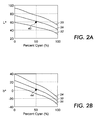
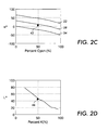
- the printer input-output characteristic or "sensitivity functions" can be represented as in Figures 2a-2d.
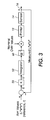
- Measured L*, a*, b* values are shown by the vector x in Figure 3.
- the Figures 2a-2d show a representative of L*, a*, b* values when C is varying at constant M and Y.
- curves 26, 28, 30 represent the curves for varying C with nominal MY values at 50%
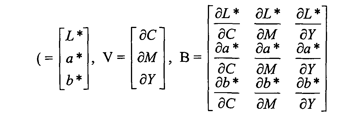
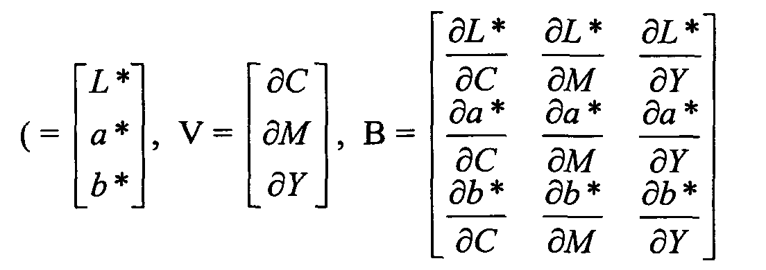
- V then represents a vector containing small deviations in C, M, Y values from the nominal C, M, Y values.
- B is a vector representing the gradient of change from the output signals x relative to the input signals about the selected nominal values from the determined sensitivity functions of Figures 2a-2d.
- Signal ( represents the state variable vector of the pixel element for the open loop system 10 .
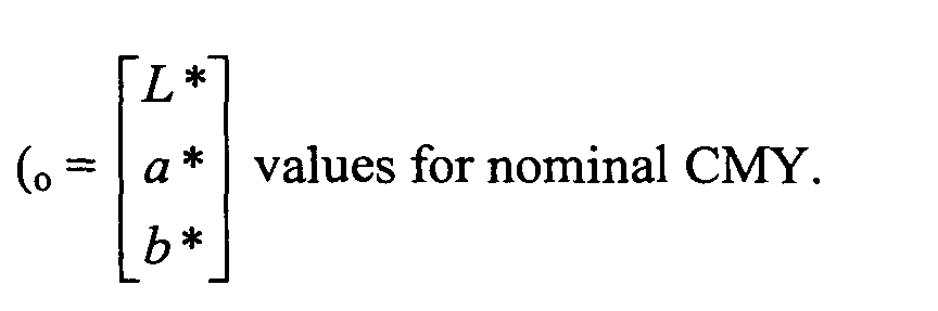
- ( o is the initial value of the state variable vector.
- Vector V is the actuator of the open loop system used for varying the state vector (.
Landscapes
- Engineering & Computer Science (AREA)
- Multimedia (AREA)
- Signal Processing (AREA)
- Facsimile Image Signal Circuits (AREA)
- Color Image Communication Systems (AREA)
- Record Information Processing For Printing (AREA)
- Color, Gradation (AREA)
- Image Processing (AREA)
Abstract
Description
In a further embodiment the constructing is for a single pixel or a macro pixel comprising a plurality of single pixels of the same color.
In a further embodiment the closed loop system controller comprises a look-up table including the inverse of the Jacobian matrix in a forward path for the loop.
In a further embodiment the open loop system comprises a representation of the state-space model of color marking device operation between device input and output as:


Claims (10)
- A method for modeling the pixel elements of a dynamically varying color reproduction device from an output image pixels generated in response to a target test including steps of :producing an image with the device in response to an input signal from the test target wherein the test target comprises a plurality of pixels;measuring with a sensor an output signal representative of the output image corresponding to a target preselected color; andconstructing a state-space model of color producing behavior for a single pixel including a matrix characterization of a gradient of change with respect to the input signal for the measured output signal
- The method as defined in claim 1 wherein the constructing includes using color sensitivity function to extract the gradient.
- The method as defined in claim 2 wherein the constructing includes forming a Jacobian matrix of a plurality of the sensitivity functions.
- The method of claim 1 further including controlling device color reproduction in accordance with the state-space model.
- The method as defined in claim 4 wherein the controlling comprises applying an inverse of the Jacobian matrix to a selected input signal for generating a corresponding output signal.
- The method as defined in claim 5 wherein the generating the corresponding output signal comprises processing the selected input signal with a look-up table including the inverse of the Jacobian matrix in a forward path of a system controller.
- The method as defined in claim 2 wherein the using the color sensitivity function comprises generating a sector of device input-output characteristics about a nominal set of measured L*, a*, b* values.
- The method as defined in claim 7 wherein the constructing the state-space model comprises assuming linearity of the sensitivity function about the nominal set of measured L*, a*, b* values.
- The method as defined in claim 7 wherein the constructing comprises representing device operation in terms of a derivative function between device input and output as:
- A color marking device including a control system for calibration of the device based upon dynamic color balance control of an output image, the system comprising:a front end converter for converting an input signal representative of a target image comprising a preselected color into a device-dependent control signal in accordance with a state-space model;a color marking device for outputting an output image in response to the control signal;a sensor for measuring a parameter from the output image representative of a color of the output image;an open loop system for comparing the parameter with a corresponding parameter from the target image and constructing a sensitivity function of output color about a selected set of nominal device color values; and,a closed loop system controller for constructing the state-space model from a gradient of the sensitivity function at the selected set of nominal device color values,whereby subsequently generated output images are output with the closed loop system controller and more accurately represent target input images.
Applications Claiming Priority (2)
| Application Number | Priority Date | Filing Date | Title |
|---|---|---|---|
| US10/348,263 US7375851B2 (en) | 2003-01-21 | 2003-01-21 | State-space based modeling of pixel elements of a dynamically varying color marking device |
| US348263 | 2003-01-21 |
Publications (2)
| Publication Number | Publication Date |
|---|---|
| EP1441506A2 true EP1441506A2 (en) | 2004-07-28 |
| EP1441506A3 EP1441506A3 (en) | 2006-02-01 |
Family
ID=32594907
Family Applications (1)
| Application Number | Title | Priority Date | Filing Date |
|---|---|---|---|
| EP04001263A Ceased EP1441506A3 (en) | 2003-01-21 | 2004-01-21 | State-space based modeling of pixel elements of a dynamically varying color marking device |
Country Status (3)
| Country | Link |
|---|---|
| US (2) | US7375851B2 (en) |
| EP (1) | EP1441506A3 (en) |
| JP (1) | JP2004229294A (en) |
Cited By (1)
| Publication number | Priority date | Publication date | Assignee | Title |
|---|---|---|---|---|
| EP2424217A3 (en) * | 2010-08-26 | 2013-07-17 | Ricoh Company, Ltd. | Apparatus and method of controlling an image forming apparatus |
Families Citing this family (17)
| Publication number | Priority date | Publication date | Assignee | Title |
|---|---|---|---|---|
| JP3689620B2 (en) * | 2000-08-31 | 2005-08-31 | キヤノン株式会社 | Image processing apparatus and method |
| DE60221248T2 (en) * | 2002-09-06 | 2008-04-03 | Agfa Graphics N.V. | Calibration of a multistage inkjet printing process |
| US8014024B2 (en) | 2005-03-02 | 2011-09-06 | Xerox Corporation | Gray balance for a printing system of multiple marking engines |
| US8699103B2 (en) * | 2005-06-15 | 2014-04-15 | Xerox Corporation | System and method for dynamically generated uniform color objects |
| US7505173B2 (en) * | 2005-06-15 | 2009-03-17 | Xerox Corporation | System and method for spatial gray balance calibration using hybrid sensing systems |
| US7800779B2 (en) * | 2005-12-21 | 2010-09-21 | Xerox Corporation | System and method for image based control using inline sensors |
| US8134740B2 (en) * | 2006-08-21 | 2012-03-13 | Xerox Corporation | Spot color controls and method |
| US7768672B2 (en) * | 2006-08-21 | 2010-08-03 | Xerox Corporation | Spot color control system and method |
| US7738140B2 (en) * | 2006-08-21 | 2010-06-15 | Xerox Corporation | System and method for automated spot color editor |
| US7990592B2 (en) * | 2008-05-27 | 2011-08-02 | Xerox Corporation | Methods and systems to produce consistent spot colors for multi-color print engines |
| US8072646B2 (en) * | 2008-06-20 | 2011-12-06 | Xerox Corporation | Apparatus and method for color control of clear coated images on media |
| US8394561B2 (en) * | 2009-07-20 | 2013-03-12 | Xerox Corporation | Colored toners |
| US8137880B2 (en) * | 2010-01-20 | 2012-03-20 | Xerox Corporation | Colored toners |
| JP5505793B2 (en) * | 2010-05-13 | 2014-05-28 | 株式会社リコー | Image forming apparatus |
| JP5618211B2 (en) * | 2011-02-09 | 2014-11-05 | 株式会社リコー | Control apparatus, image forming apparatus, and control method |
| US9213287B1 (en) * | 2014-07-31 | 2015-12-15 | Eastman Kodak Company | Document registration using registration error model |
| DE102018222260A1 (en) * | 2018-12-19 | 2020-06-25 | Robert Bosch Gmbh | Method and device for processing an image signal of an image sensor for a vehicle |
Family Cites Families (12)
| Publication number | Priority date | Publication date | Assignee | Title |
|---|---|---|---|---|
| US5357448A (en) * | 1993-02-02 | 1994-10-18 | Quad/Tech, Inc. | Method and apparatus for controlling the printing of an image having a plurality of printed colors |
| US5508826A (en) | 1993-04-27 | 1996-04-16 | Lloyd; William J. | Method and apparatus for calibrated digital printing using a four by four transformation matrix |
| JP3714701B2 (en) | 1995-06-22 | 2005-11-09 | 富士写真フイルム株式会社 | Color conversion method |
| EP0769869B1 (en) * | 1995-10-20 | 2007-09-26 | FUJIFILM Corporation | System for generating proof |
| US5708916A (en) * | 1996-11-26 | 1998-01-13 | Xerox Corporation | Developed mass per unit area controller without using electrostatic measurements |
| US6278533B1 (en) * | 1996-11-29 | 2001-08-21 | Fuji Photo Film Co., Ltd. | Method of processing image signal |
| US6236474B1 (en) * | 1998-05-22 | 2001-05-22 | Xerox Corporation | Device independent color controller and method |
| US6157469A (en) * | 1998-05-22 | 2000-12-05 | Xerox Corporation | Dynamic device independent image correction method and apparatus |
| US6744531B1 (en) * | 1998-12-29 | 2004-06-01 | Xerox Corporation | Color adjustment apparatus and method |
| US6809837B1 (en) * | 1999-11-29 | 2004-10-26 | Xerox Corporation | On-line model prediction and calibration system for a dynamically varying color reproduction device |
| US6934053B1 (en) * | 2000-01-19 | 2005-08-23 | Xerox Corporation | methods for producing device and illumination independent color reproduction |
| US7513952B2 (en) * | 2001-10-31 | 2009-04-07 | Xerox Corporation | Model based detection and compensation of glitches in color measurement systems |
-
2003
- 2003-01-21 US US10/348,263 patent/US7375851B2/en not_active Ceased
-
2004
- 2004-01-20 JP JP2004011614A patent/JP2004229294A/en active Pending
- 2004-01-21 EP EP04001263A patent/EP1441506A3/en not_active Ceased
-
2010
- 2010-05-19 US US12/782,812 patent/USRE42673E1/en not_active Expired - Fee Related
Cited By (1)
| Publication number | Priority date | Publication date | Assignee | Title |
|---|---|---|---|---|
| EP2424217A3 (en) * | 2010-08-26 | 2013-07-17 | Ricoh Company, Ltd. | Apparatus and method of controlling an image forming apparatus |
Also Published As
| Publication number | Publication date |
|---|---|
| JP2004229294A (en) | 2004-08-12 |
| EP1441506A3 (en) | 2006-02-01 |
| USRE42673E1 (en) | 2011-09-06 |
| US7375851B2 (en) | 2008-05-20 |
| US20040141193A1 (en) | 2004-07-22 |
Similar Documents
| Publication | Publication Date | Title |
|---|---|---|
| USRE42673E1 (en) | State-space based modeling of pixel elements of a dynamically varying color marking device | |
| US6157469A (en) | Dynamic device independent image correction method and apparatus | |
| CA2345908C (en) | On-line calibration system for a dynamically varying color marking device | |
| Vrhel et al. | Color device calibration: A mathematical formulation | |
| EP0891078B1 (en) | Colour correction apparatus and method for an image system | |
| EP0648042B1 (en) | Colour reproduction system | |
| JP2001209788A (en) | Online model predicting method of dynamically fluctuating color reproducing device and color printer | |
| JPH06141175A (en) | Calibration architecture of color printer | |
| JP2001197325A (en) | Color managing system incorporating parameter control channel | |
| US6330078B1 (en) | Feedback method and apparatus for printing calibration | |
| US7782490B2 (en) | Sensitivity matrix determination for adaptive color control | |
| EP1156666B1 (en) | Color-balanced TRC correction to compensate for illuminant changes in printer characterization | |
| US8314978B2 (en) | Halftone independent device characterization accounting for colorant interactions | |
| JP4449503B2 (en) | Image processing device | |
| US7229146B2 (en) | System and method for characterizing a printing device | |
| US8928901B2 (en) | Generating an image profile LUT for a N-color marking device via multi-objective cost minimization | |
| US7595910B2 (en) | Method for making a dot for dot proof | |
| JP3209053B2 (en) | Color reproduction device | |
| JP2004147257A (en) | Color prediction model creation method, color prediction model creation device, program, and storage medium | |
| JPH06326861A (en) | Color conversion parameter setting method | |
| EP1596576A2 (en) | Method for closed loop characterization | |
| JP4532797B2 (en) | Image processing method and image processing apparatus | |
| JP4545995B2 (en) | Image processing method and image processing apparatus | |
| EP1495631B1 (en) | System and method for characterizing a printing device | |
| JPH10191087A (en) | Color correction device |
Legal Events
| Date | Code | Title | Description |
|---|---|---|---|
| PUAI | Public reference made under article 153(3) epc to a published international application that has entered the european phase |
Free format text: ORIGINAL CODE: 0009012 |
|
| AK | Designated contracting states |
Kind code of ref document: A2 Designated state(s): AT BE BG CH CY CZ DE DK EE ES FI FR GB GR HU IE IT LI LU MC NL PT RO SE SI SK TR |
|
| AX | Request for extension of the european patent |
Extension state: AL LT LV MK |
|
| PUAL | Search report despatched |
Free format text: ORIGINAL CODE: 0009013 |
|
| AK | Designated contracting states |
Kind code of ref document: A3 Designated state(s): AT BE BG CH CY CZ DE DK EE ES FI FR GB GR HU IE IT LI LU MC NL PT RO SE SI SK TR |
|
| AX | Request for extension of the european patent |
Extension state: AL LT LV MK |
|
| 17P | Request for examination filed |
Effective date: 20060801 |
|
| AKX | Designation fees paid |
Designated state(s): DE FR GB |
|
| 17Q | First examination report despatched |
Effective date: 20060913 |
|
| STAA | Information on the status of an ep patent application or granted ep patent |
Free format text: STATUS: THE APPLICATION HAS BEEN REFUSED |
|
| 18R | Application refused |
Effective date: 20151116 |