EP1441427A1 - Method of making metallic shell for spark plug, method of making spark plug having metallic shell and spark plug produced by the same - Google Patents
Method of making metallic shell for spark plug, method of making spark plug having metallic shell and spark plug produced by the same Download PDFInfo
- Publication number
- EP1441427A1 EP1441427A1 EP04250241A EP04250241A EP1441427A1 EP 1441427 A1 EP1441427 A1 EP 1441427A1 EP 04250241 A EP04250241 A EP 04250241A EP 04250241 A EP04250241 A EP 04250241A EP 1441427 A1 EP1441427 A1 EP 1441427A1
- Authority
- EP
- European Patent Office
- Prior art keywords
- end side
- tubular portion
- metallic shell
- blank
- hole section
- Prior art date
- Legal status (The legal status is an assumption and is not a legal conclusion. Google has not performed a legal analysis and makes no representation as to the accuracy of the status listed.)
- Granted
Links
- 238000004519 manufacturing process Methods 0.000 title claims abstract description 16
- 238000000034 method Methods 0.000 claims abstract description 47
- 239000002184 metal Substances 0.000 claims abstract description 16
- 239000007858 starting material Substances 0.000 claims abstract description 11
- 238000005520 cutting process Methods 0.000 claims abstract description 8
- 239000012212 insulator Substances 0.000 claims description 21
- 238000001125 extrusion Methods 0.000 claims description 14
- 230000004323 axial length Effects 0.000 claims description 4
- 238000005304 joining Methods 0.000 claims description 2
- 238000010273 cold forging Methods 0.000 description 9
- 230000002093 peripheral effect Effects 0.000 description 4
- 238000003754 machining Methods 0.000 description 3
- 238000002485 combustion reaction Methods 0.000 description 2
- 238000007599 discharging Methods 0.000 description 2
- 239000011521 glass Substances 0.000 description 2
- 238000012986 modification Methods 0.000 description 2
- 230000004048 modification Effects 0.000 description 2
- 239000007787 solid Substances 0.000 description 2
- PNEYBMLMFCGWSK-UHFFFAOYSA-N Alumina Chemical compound [O-2].[O-2].[O-2].[Al+3].[Al+3] PNEYBMLMFCGWSK-UHFFFAOYSA-N 0.000 description 1
- 229910001209 Low-carbon steel Inorganic materials 0.000 description 1
- 239000000919 ceramic Substances 0.000 description 1
- 238000007796 conventional method Methods 0.000 description 1
- 239000000945 filler Substances 0.000 description 1
- 238000005242 forging Methods 0.000 description 1
- 239000000446 fuel Substances 0.000 description 1
- 238000009434 installation Methods 0.000 description 1
- 239000000203 mixture Substances 0.000 description 1
- 239000000843 powder Substances 0.000 description 1
- 238000002203 pretreatment Methods 0.000 description 1
- 230000005855 radiation Effects 0.000 description 1
- 102220053993 rs28929485 Human genes 0.000 description 1
- 102200082907 rs33918131 Human genes 0.000 description 1
- 102200082816 rs34868397 Human genes 0.000 description 1
- 102220342298 rs777367316 Human genes 0.000 description 1
Images


Classifications
-
- B—PERFORMING OPERATIONS; TRANSPORTING
- B21—MECHANICAL METAL-WORKING WITHOUT ESSENTIALLY REMOVING MATERIAL; PUNCHING METAL
- B21K—MAKING FORGED OR PRESSED METAL PRODUCTS, e.g. HORSE-SHOES, RIVETS, BOLTS OR WHEELS
- B21K21/00—Making hollow articles not covered by a single preceding sub-group
- B21K21/08—Shaping hollow articles with different cross-section in longitudinal direction, e.g. nozzles, spark-plugs
-
- H—ELECTRICITY
- H01—ELECTRIC ELEMENTS
- H01T—SPARK GAPS; OVERVOLTAGE ARRESTERS USING SPARK GAPS; SPARKING PLUGS; CORONA DEVICES; GENERATING IONS TO BE INTRODUCED INTO NON-ENCLOSED GASES
- H01T21/00—Apparatus or processes specially adapted for the manufacture or maintenance of spark gaps or sparking plugs
- H01T21/02—Apparatus or processes specially adapted for the manufacture or maintenance of spark gaps or sparking plugs of sparking plugs
Definitions
- the present invention relates to a method of making a metallic shell for a spark plug. Further, the present invention relates to a method of making a spark plug having a metallic shell and a spark plug produced by the same.
- a spark plug serves as a spark discharging means in an ignition system and includes a tubular metallic shell.
- the metallic shell is so shaped as to have a stepped, concentric through hole including, in the order from a basic end side to a tip end side thereof, a large diameter hole Section, an intermediate diameter hole section smaller in diameter than the large diameter hole section and a small diameter hole section smaller in diameter than the intermediate hole section.
- tip end side is herein used to indicate the side where a spark discharging section of a spark plug is located.
- the above-described metallic shell is formed from a solid round metal bar that is cut to a predetermined length, by a suitable combination of extrusion or cold forging processes, piercing processes, etc. as disclosed in Unexamined Japanese Patent Publication No. 7-16693.
- the multi-stepped hole (having the large diameter hole section, intermediate diameter hole section and small diameter hole section) of the metallic shell is required to be smaller in diameter and longer in length.
- the method of the above-described Japanese Patent Publication has a possibility of being encountered by a problem that tools such as piercing punches necessary for forming the multi-stepped hole are subjected to large loads and therefore quite short in life and a problem that there is a difficulty in attaining a desired straightness of the multi-stepped hole.
- a method of making a metallic shell for a spark plug including a concentric through hole, an intermediate tubular portion, a tip end side tubular portion disposed on a tip end side of the intermediate tubular portion and a base end side tubular portion disposed on a base end side of the intermediate tubular portion, the through hole including, in the order from a base end side to a tip end side, a large diameter hole section, an intermediate diameter hole section smaller in diameter than the large diameter hole section and a small diameter hole section smaller in diameter than the intermediate hole section, the method comprising the steps of cutting a metal pipe that is used as a starting material to a predetermined length and thereby preparing a pipe-shaped blank, and subjecting the blank to a deformation process and thereby forming the blank into the metallic shell.
- a method of making a metallic shell for a spark plug comprising the steps of cutting a metal pipe that is uses as a starting material to a predetermined length and thereby preparing a pipe-shaped blank, subjecting the blank to a deformation process and thereby forming the blank into the metallic shell, installing an insulator assembly having an insulator in which a center electrode and a terminal member are installed in the metallic shell by inserting the insulator assembly into the metallic shell from the base end side thereof,
- Spark plugs having metallic shells manufactured by the methods described above can thus be produced.
- a spark plug comprising an insulator having a multi-stepped through hole, a center electrode disposed in the through hole so as to be positioned at a tip end side thereof, a metallic shell made up of a tubular member having a through hole within which the insulator is disposed, and a ground electrode having an end connected to the metallic shell and the other end portion disposed opposite to the center electrode, wherein the metallic shell is formed from a metal pipe having a predetermined inner diameter, a smallest diameter hole section of the multi-stepped through hole of the metallic shell having a diameter equal to the inner diameter of the pipe.
- a spark plug is generally indicated by 1 and includes a tubular metallic shell 2 having a concentric, multi-stepped through hole 8, a tubular insulator 3 disposed in the through hole 8 having a concentric through hole 3H, a center electrode 4 disposed in a tip end side portion of the through hole 3H and a ground electrode 5 having one end fixedly attached to a tip end face of the metallic shell 2 and the other end side disposed opposite to the tip end face of the center electrode 4.
- the metallic shell 2 is tubular and has an intermediate tubular portion 21 having an outer circumferential periphery protruded radially outward, a tip end side tubular portion 22 smaller in outer diameter than the intermediate tubular portion 21 and disposed on the tip end side of the intermediate tubular portion 21 and a base end side tubular portion 23 disposed on the base end side of the intermediate tubular portion 21.
- the tip end side tubular portion 22 has on the outer circumferential surface thereof a male thread 6 by means of which the spark plug 1 is screwed onto a cylinder head (not shown), etc. and at the tip end side outer peripheral edge a chamfered or beveled portion 6X.
- the base end side tubular portion 23 has a tool engagement section 231 which is engaged by a tool such as a wrench at the time of installation of the spark plug 1 to the cylinder head or the like.
- the base end side tubular portion 23 further has at a base end side of the tool engagement section 231 a caulking section 232 used for fixing the insulator 3 to the metallic shell 2 by caulking.
- the multi-stepped through hole 8 has, in order from the base end side to the tip end side, a large diameter hole section 8L, an intermediate diameter hole section 8M smaller in diameter than the large diameter hole section 8L and a small diameter hole section 8S smaller in diameter than the intermediate diameter hole section 8M that are arranged successively. In the meantime, in FIG.
- the metallic shell 2 is shaped so that the length L from the end face of the intermediate tubular portion 21 to the tip end face of the tip end side tubular portion 22 is 25 mm and the outer diameter D of the tip end side tubular portion 22 is 10.1 mm.
- the insulator 3 is made of alumina ceramic and has the through hole 3H extending axially thereof. Also, within the through hole 3H and at the tip end side thereof is disposed the center electrode 4. Within the through hole 3H and at the base end side thereof is fixed a terminal member 7 for applying a high voltage to the center electrode 4. Further, within the through hole 3H and between the center electrode 4 and the terminal member 7 is disposed a resistor 9. The resistor 9 is electrically connected at the opposite ends thereof to center electrode 4 and the terminal member 7 by way of electrically conductive glass seal layers 10. Also by the electrically conductive glass seal layers 10, the center electrode 4, resistor 9 and the terminal member 7 are hermetically sealed with respect to the through hole 3H.
- the insulator 3 includes a protruded portion 31 that protrudes radially outward so as to fittingly engage the large diameter hole section 8L when the insulator 3 is fitted in the metallic shell 2, a base end portion 32 located on the base end side of the protruded portion 31 and smaller in outer diameter than the large diameter hole section 8L of the metallic shell 2, an intermediate portion 33 disposed on the tip end side of the protruded portion 31 and engaging the intermediate diameter hole section 8M when the insulator 3 is fitted in the metallic shell 2, and a tip end portion or leg portion 34 that forms a space within the small diameter hole section 8S when the insulator 3 is fitted in the metallic shell 2.
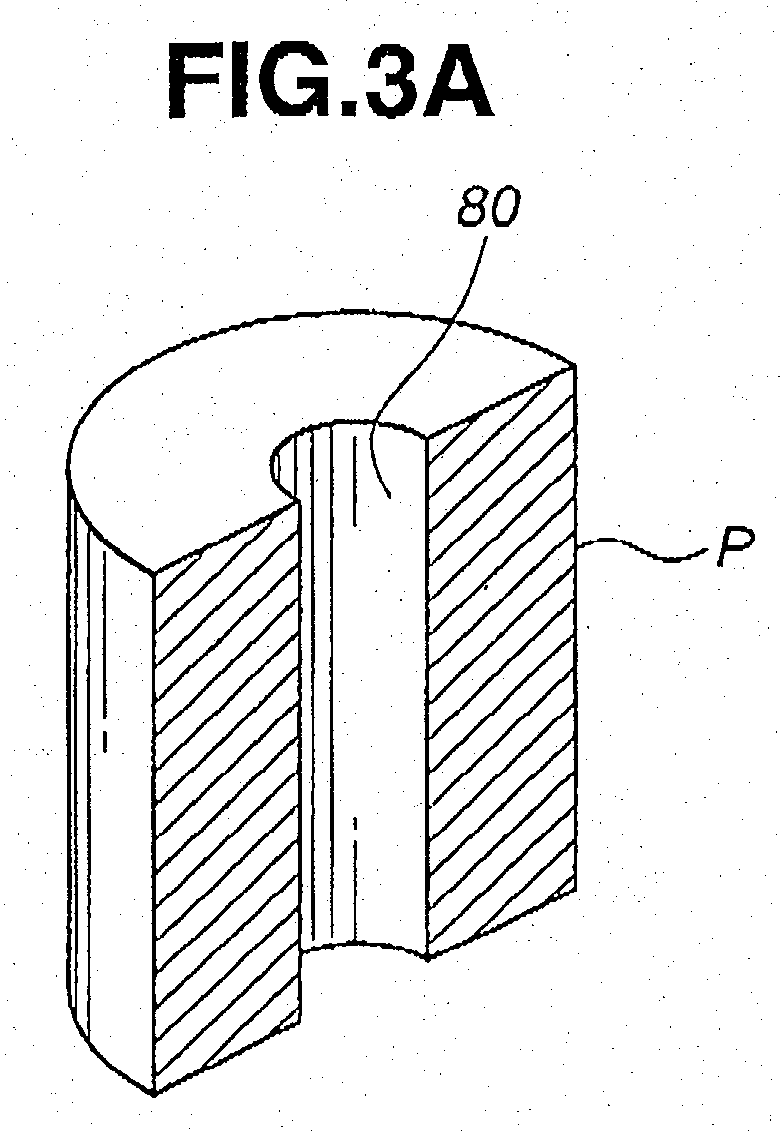
- a pipe that is used as a starting material for a method of making a metallic shell is cut to a predetermined length thereby preparing a pipe-shaped blank P shown in FIG. 3A.
- the blank P is made of a low carbon steel such as S10C, S17C, S25C, S45C, SVS430 that are prescribed in Japanese Industrial standards and has a concentric through hole 80 that is equal in diameter to the small diameter hole section 8S of the multi-stepped through hole 8.
- the outer diameter of the blank P is equal to that of the intermediate tubular portion 21 of the metallic shell 2.
- the inner and outer diameters of the blank P may be adjusted to size by pretreatments that are carried out prior to subjecting the blank P to a deformation process.
- the blank P is loaded in a forging die of a cold forging machine and the tip end side tubular portion 22 is formed by extrusion or cold forging.
- a pin 11 of such a thickness as to fit in the through hole 80 is first inserted into the hole 80.
- the blank P is inserted into a die 12 together with the pin 11 and pushed down by a punch (no numeral) such that the tip end side tubular portion 22 is formed by extrusion.
- the leading end portion of the pin 11 is adapted to move into a kick-out sleeve 13 (which may be integral with the die 12) to be supported thereby.
- an upper portion of the blank P above the tip end side tubular portion 22 maintains an initial outer diameter, i.e., an outer diameter equal to that of the intermediate tubular portion 21.
- a punch 14 with a pin equal in diameter to the pin 11 is inserted into the through hole 80 of the blank P and pushed down such that the upper part of the through hole 80 is expanded to form the large diameter hole section 8L of the stepped hole 8 by extrusion or cold forging.
- the leading end portion of the punch 14 is adapted to move into a kick-out sleeve 15 (the kick-out sleeve 15 may be formed integral with a die 16) to be supported thereby.
- the portion of the blank P above the tip end side tubular portion 22 maintains an outer diameter equal to that of the intermediate tubular portion 21.
- a mandrel 17 is inserted into an upper part of the through hole 80, while surrounding the upper part of the blank P above the tip end side tubular portion 22 by an upper die (no numeral) having a stepped hole including a larger diameter hole section equal in diameter to the outer circumferential periphery of the intermediate tubular portion 21 and a smaller diameter hole section equal in diameter to the outer circumferential periphery of the base end side tubular portion such that the base end side tubular portion 23 is formed by backward extrusion or cold forging.
- the base end side tubular portion 23 in this embodiment has a hexagonal outer peripheral shape as shown in FIG. 3B.
- the outer peripheral shape of the base end side tubular portion 23 is not limited to the hexagonal shape but can be any other shape such as a so-called Bi-HEX shape.
- the blank P having been processed as above is loaded in a die 20 and a stepped punch 18 is pushed into the axial through hole 80 so that the intermediate diameter hole section 8M of the stepped hole 8 is formed by extrusion or cold forging.
- the punch 18 is multi-stepped to have a small diameter portion, intermediate diameter portion and larger diameter portion that are equal in diameter to the small diameter hole section 8S; intermediate diameter hole section 8M and large diameter hole section L, respectively.
- the small diameter portion of the punch 18 is adapted to move into a kick-out sleeve 19 (which may be integral with a die 20) to be supported thereby.
- the die 20 has a through hole (no numeral) with a smaller diameter hole section of the diameter equal to the outer diameter of the tip end side tubular portion 22 and a larger diameter hole section of a diameter equal to the outer diameter of the intermediate tubular portion 21.
- FIGS. 1A to 1D the order of the steps can be changed, i.e., the step of FIG. 1C and the step of FIG. 1D can be replaced with each other.
- the steps of such a method are shown in FIGS. 2A to 2D and the description thereto is omitted for brevity since it will be the same as that of the steps of FIGS. 1A to 1D except for replacement of the description of FIG. 1C with that of FIG. 1D.
- a metallic shell intermediate article 200 shown in FIG. 3B is obtained.
- the metallic shell intermediate article 200 is formed at the tip end side tubular portion 22 with the male thread 6 (refer to FIG. 4) and the chamfered or beveled portion 6X.
- the base end of the base end side tubular portion 23 is cut or machined so as to be formed with a caulking section 232. Further, the tool engagement section 231 is finished by suitable cutting or machining, whereby the metallic shell 2 is completed.
- the insulator 3 receiving therewithin the center electrode 4 as shown in FIG. 4, and the caulking section 232 is bent inward, i.e., caulked.
- This causes the protruded portion 31 of the insulator 3 to be lockingly engaged with the caulking section 232 of the metallic shell 2 by way of rings 100 and ceramic filler powder 101, while causing a shoulder section between the intermediate diameter hole section 8M and the small diameter hole section as and a shoulder section between the intermediate portion 33 and the leg portion 34 to be abuttingly engaged with each other.
- the insulator 3, etc. are installed in the metallic shell 2, whereby the assemblage of the spark plug 3 is completed.
- a metal pipe is used as a starting material in the method of making a metallic shell, that is, a pipe is used for preparing a pipe-shaped blank P.
- This can dispense with piercing or perforating of the through hole 80 of the blank P and therefore the tools such as a punch and die for such piercing or perforating.
- the method described above makes it possible to form the multi-stepped hole straightly, in a way as to allow the multi-stepped hole to have a good straightness, thus making it possible to produce a spark plug of a small sized and long reach type with a high accuracy and at low cost.
- the inner diameter of a pipe that is used as a starting material is larger than the small diameter hole section 8S and smaller than the large diameter hole section 8L of the multi-stepped hole 8.
- an amount of metal to be processed i.e., an amount of metal that is caused to flow for forming the multi-stepped hole 8
- the inner diameter of the pipe is preferably made equal to one of the large diameter hole section 8L, intermediate diameter hole section 8M and small diameter hole section 8S of the multi-stepped hole 8.
- the inner diameter of the pipe is equal to the diameter of the small diameter hole section 8S. This can dispense with processing of the small diameter hole section 8S, thus making it possible to elongate the life of the tools used in carrying out the method and produce the metallic shell at low cost.
- the outer diameter of the pipe that is used as a starting material is larger than that of the tip end side tubular portion 22 of the metallic shell 2 and smaller than the intermediate tubular portion 21 of the metallic shell 2.
- the amount of metal to be processed i.e., an amount of metal caused to flow for forming the tip end side tubular portion 22, intermediate tubular portion 21 and base end side tubular portion 23
- the amount of metal to be processed can be smaller, thus making it possible to elongate the life of the tools or dies used for carrying out the method and produce the metallic shell 2 with a high accuracy and at low cost.
- the outer diameter of the pipe that is used as a starting material be equal to that of one of the tip end side tubular portion 22, intermediate tubular portion 21 and base end side tubular portion 23. This can dispense with processing of the tubular portion of an outer diameter to which the outer diameter of the pipe is made equal, thus making it possible to further elongate the life of the tools used in the method and produce the metallic shell 2 with a higher accuracy and at lower cost.
- the method of the present invention makes it possible to produce a metallic shell with a straight multi-stepped hole assuredly even if the final shape of the metallic shell is of such dimensions that a length L from an end face of the intermediate tubular portion to a tip end face of the tip end side tubular portion exceeds 19 mm (i.e., of so-called long reach type). This makes it possible to elongate the life of the tools used in the method.
- the method of the present invention makes it possible to produce a metallic shell with a straight multi-stepped hole assuredly even if the final shape of the metallic shell is of such dimensions that the front end diameter D of the tip end side tubular portion is less than 10.5 mm. This makes it possible to elongate the life of the tools used in the method.
- the front end diameter D is intended to indicate the diameter of the front end of the metallic shell excluding the chamfered corner portion. Accordingly, the present invention is applicable to a spark plug of the type that does not have any thread on the outer peripheral surface thereof, i.e., of a so-called unthreaded type.
- the method of the present invention makes it possible to produce a metallic shell with ease even if the final shape of the metallic shell is of such dimensions that an axial length T of the small diameter hole section exceeds 2 mm, the metallic shell of such dimensions having a difficulty of being produced.
- the metallic shell 2 of the spark plug 1 is formed from the pipe-shaped blank P that is prepared by using the metal pipe having a predetermined inner diameter that is made equal to that of the small diameter hole section 8S (i.e., the smallest diameter hole section). That is, the small diameter hole section 8S of the metallic shell 2 can be obtained by utilizing the inner diameter of the pipe as it is, thus making it possible to dispense with processing of the small diameter hole section 8S and therefore making it possible to obtain the spark plug 1 that is highly accurate and produced at low cost. Further, the hole sections of the metallic shell 2 other than the small diameter hole section 8S is formed by enlarging the inner diameter of the pipe. This enables the multi-stepped hole 8 of the metallic shell 2 to be formed by utilizing the axis of the pipe, thus making it possible to obtain the spark plug 1 with the metallic shell 2 having the multi-stepped hole 8 of a good straightness.
- the lower half of the small diameter hole section 8S' of the multi-stepped hole 8 of the intermediate article 200' may be expanded so as to be nearly equal in diameter to the intermediate diameter hole section 8M.
- a cold forging step for forming such an expanded hole section by a punch that is inserted into the hole 80 from the lower side thereof is added to the middle or the end of the steps of FIGS. 1A to 1D or FIGS. 2A to 2D.
- the metallic shell 2 that can be made by the method of the present invention can be varied in size variously but the method of the present invention can exert most usefulness in case the final shape of the metallic shell 2, as in the embodiment described above, is of such dimensions that the length L (refer to FIG. 4) from the end face of the intermediate tubular portion 21 to the tip end face of the tip end side tubular portion 22 exceeds 19 mm or the tip end diameter D (refer to FIG.
Landscapes
- Engineering & Computer Science (AREA)
- Mechanical Engineering (AREA)
- Manufacturing & Machinery (AREA)
- Spark Plugs (AREA)
- Forging (AREA)
Abstract
Description
Claims (12)
- A method of making a metallic shell (2) for a spark plug (1), the metallic shell (2) including a multi-stepped through hole (8), an intermediate tubular portion (21), a tip end side tubular portion (22) disposed on a tip end side of the intermediate tubular portion (21) and a base end side tubular portion (23) disposed on a base end side of the intermediate tubular portion (21), the through hole (8) including, in the order from a base end side to a tip end side of the spark plug (1), a large diameter hole section (8L), an intermediate diameter hole section (8M) smaller in diameter than the large diameter hole section (8L) and a small diameter hole section (8S) smaller in diameter than the intermediate diameter hole section (8M), the method comprising the steps of;
cutting a metal pipe that is used as a starting material to a predetermined length and thereby preparing a pipe-shaped blank (P); and
subjecting the blank (P) to a deformation process and thereby forming the blank (P) into the metallic shell (2). - A method according to claim 1 , wherein an inner diameter of the pipe is larger than a diameter of the small diameter hole section (8S) and smaller than a diameter of the large diameter hole section (8L)·
- A method according to claim 1 or 2 wherein an inner diameter of the pipe is equal to a diameter of the small diameter hole section (8S).
- A method according to any one of claims 1 to 3, wherein an outer diameter of the pipe is larger than that of the tip end side tubular portion (22) of the metallic shell (2) and smaller than that of the intermediate tubular portion (21).
- A method according to any one of claims 1 to 4, further comprising:after the step of cutting, a second step of forming by extrusion a tip end side portion of the blank (P) into the tip end side tubular portion (22) smaller in outer diameter than the blank (P);a third step of processing a base end side of the blank (P) by extrusion to partially expand a through hole (80) of the blank (P) and thereby forming the large diameter hole section (8L);a fourth step of processing the base end side of the blank (P) by extrusion and thereby forming the base end side tubular portion (23) that is smaller in outer diameter than the blank (P) while at the same time forming the intermediate tubular portion (21); anda fifth step of processing the base end side of the blank (P) by extrusion to partially expand the through hole (80) of the blank (P) and thereby forming the intermediate diameter hole section (8M) while at the same time forming the small diameter hole section (8S):
- A method according to any one of claims 1 to 4, further comprising:after the step of cutting, a second step of forming by extrusion a tip end side portion of the blank (P) into the tip end side tubular portion (22) smaller in outer diameter than the blank (P):a third step of processing a base end side of the blank (P) by extrusion to partially expand a through hole (8) of the blank (P) and thereby forming the large diameter hole section (8L);a fourth step of processing the base end side of the blank (P) by extrusion to partially expand the through hole (80) of the blank (P) and thereby forming the intermediate diameter hole section (8M) while at the same time forming the small diameter hole section (8S); anda fifth step of processing the base end side of the blank (P) by extrusion and thereby forming the base end side of the blank (P) into the base end side tubular portion (23) smaller in outer diameter than the blank (P) while at the same time forming the intermediate tubular portion (21).
- A method according to any one of claims 1 to 6, wherein a final shape of the metallic shell (2) is of such dimensions that a length (L) from an end face of the intermediate tubular portion (21) to a tip end face of the tip end side tubular portion (22) exceeds 19 mm.
- A method according to any one of claims 1 to 6, wherein the final shape of the metallic shell (2) is of such dimensions that a tip end diameter (D) of the tip end side tubular portion (22) is less than 10.5 mm.
- A method according to any one of claims 1 to 8, wherein a final shape of the metallic shell (2) is sized so that an axial length (T) of the small diameter hole section (8S) exceeds 2 mm.
- A method of making a metallic shell (2) for a spark plug (1), the metallic shell (2) including a concentric through hole (8), an intermediate tubular portion (21), a tip end side tubular portion (22) disposed on a tip end side of the intermediate tubular portion (21) and a base end side tubular portion (23) disposed on a base end side of the intermediate tubular portion (21), the through hole(8) including, in the order from a base end side to a tip end side of the spark plug (1), a large diameter hole section (8L), an intermediate diameter hole section (8M) smaller in diameter than the large diameter hole section (8L) and a small diameter hole section (8S) smaller in diameter than the intermediate diameter hole section (8M), the method comprising the steps of;cutting a metal pipe that is used as a starting material to a predetermined length and thereby preparing a pipe-shaped blank (P);subjecting the blank (P) to a deformation process and thereby forming the blank into the metallic shell (2);installing an insulator assembly having an insulator (3) in which a center electrode (4) and a terminal member (7) are installed in the metallic shell (2) by inserting the insulator assembly into the metallic shell (2) from the base end side thereof; andjoining an end of a ground electrode (5) to a tip end of the metallic shell (2) and making another end side of the ground electrode (5) be disposed opposite to the center electrode (4).
- A spark plug (1) comprising:wherein the metallic shell (2) is formed from a metal pipe having a predetermined inner diameter, a smallest diameter hole section (8S) of the multi-stepped through hole (8) of the metallic shell (2) having a diameter equal to the inner diameter of the pipe.an insulator (3) having an axial through hole (3H);a center electrode (4) disposed in the through hole (3H) of the insulator (3) so as to be positioned at a tip end side thereof;a metallic shell (2) having a multi-stepped through (8) hole within which the insulator (3) is disposed; anda ground electrode (5) having an end connected to the metallic shell (2) and the other end portion disposed opposite to the center electrode (4);
- A spark plug according to claim 11, wherein the smallest diameter hole section (8S) is of an axial length (T) that exceeds 2 mm.
Applications Claiming Priority (2)
| Application Number | Priority Date | Filing Date | Title |
|---|---|---|---|
| JP2003012763 | 2003-01-21 | ||
| JP2003012763 | 2003-01-21 |
Publications (2)
| Publication Number | Publication Date |
|---|---|
| EP1441427A1 true EP1441427A1 (en) | 2004-07-28 |
| EP1441427B1 EP1441427B1 (en) | 2008-02-27 |
Family
ID=32588629
Family Applications (1)
| Application Number | Title | Priority Date | Filing Date |
|---|---|---|---|
| EP04250241A Expired - Lifetime EP1441427B1 (en) | 2003-01-21 | 2004-01-19 | Method of making metallic shell for spark plug, method of making spark plug having metallic shell and spark plug produced by the same |
Country Status (3)
| Country | Link |
|---|---|
| US (1) | US7172483B2 (en) |
| EP (1) | EP1441427B1 (en) |
| DE (1) | DE602004012002T2 (en) |
Cited By (1)
| Publication number | Priority date | Publication date | Assignee | Title |
|---|---|---|---|---|
| WO2011031987A3 (en) * | 2009-09-11 | 2011-06-30 | Woodward, Inc. | Method for forming an electrode for a spark plug |
Families Citing this family (5)
| Publication number | Priority date | Publication date | Assignee | Title |
|---|---|---|---|---|
| US7517235B2 (en) | 2006-12-28 | 2009-04-14 | General Electric Company | Press fit connection for mounting electrical plug-in outlet insulator to a busway aluminum housing |
| WO2009097320A2 (en) * | 2008-01-28 | 2009-08-06 | Honeywell International Inc. | Dielectric enhanced partial thread spark plug |
| JP4741687B2 (en) * | 2009-03-03 | 2011-08-03 | 日本特殊陶業株式会社 | Manufacturing method of metal shell for spark plug |
| JP4834764B2 (en) * | 2009-11-12 | 2011-12-14 | 日本特殊陶業株式会社 | Manufacturing method of spark plug |
| JP6212349B2 (en) * | 2013-10-14 | 2017-10-11 | 日本特殊陶業株式会社 | Spark plug metal shell manufacturing method, spark plug metal shell manufacturing method, and spark plug manufacturing method |
Citations (3)
| Publication number | Priority date | Publication date | Assignee | Title |
|---|---|---|---|---|
| US1701401A (en) * | 1926-07-12 | 1929-02-05 | Gen Motors Corp | Method of making spark plugs |
| CH317554A (en) * | 1952-09-30 | 1956-11-30 | Bosch Gmbh Robert | Process for extrusion of hollow bodies |
| DE10128397A1 (en) * | 2001-06-12 | 2002-12-19 | Volkswagen Ag | Spark ignition plug for internal combustion engine has insulating body containing electrode and made of material with relative dielectric constant of less than four or between two and three |
Family Cites Families (10)
| Publication number | Priority date | Publication date | Assignee | Title |
|---|---|---|---|---|
| CA645083A (en) * | 1962-07-17 | Fischer Hans | Production of hollow bodies by pressing | |
| US1726264A (en) * | 1928-08-17 | 1929-08-27 | Francis F Hamilton | Method of making spark plugs |
| US3186209A (en) * | 1960-04-14 | 1965-06-01 | Nat Machinery Co | Method of cold forming an elongated hollow article |
| JPS59102039A (en) * | 1982-12-02 | 1984-06-12 | 三宅 晃 | Sleeve for anchor bolt |
| JPS6166018A (en) | 1984-09-08 | 1986-04-04 | Tsukiboshi Seisakusho:Kk | Manufacture of housing of glow plug for diesel engine |
| DE69016848T2 (en) * | 1989-06-21 | 1995-06-08 | Ngk Spark Plug Co | Process for producing a hollow body. |
| JP2965360B2 (en) | 1991-01-11 | 1999-10-18 | 日本特殊陶業株式会社 | Manufacturing method of metal shell for glow plug |
| JP3431950B2 (en) | 1993-07-02 | 2003-07-28 | 日本特殊陶業株式会社 | Manufacturing method of metal shell for spark plug |
| JP2853015B2 (en) * | 1995-04-14 | 1999-02-03 | 株式会社月星製作所 | Method of manufacturing glow plug housing |
| JP3936230B2 (en) * | 2002-04-19 | 2007-06-27 | 日本特殊陶業株式会社 | Manufacturing method of flanged tubular metal fittings |
-
2004
- 2004-01-19 DE DE602004012002T patent/DE602004012002T2/en not_active Expired - Lifetime
- 2004-01-19 EP EP04250241A patent/EP1441427B1/en not_active Expired - Lifetime
- 2004-01-20 US US10/759,281 patent/US7172483B2/en not_active Expired - Lifetime
Patent Citations (3)
| Publication number | Priority date | Publication date | Assignee | Title |
|---|---|---|---|---|
| US1701401A (en) * | 1926-07-12 | 1929-02-05 | Gen Motors Corp | Method of making spark plugs |
| CH317554A (en) * | 1952-09-30 | 1956-11-30 | Bosch Gmbh Robert | Process for extrusion of hollow bodies |
| DE10128397A1 (en) * | 2001-06-12 | 2002-12-19 | Volkswagen Ag | Spark ignition plug for internal combustion engine has insulating body containing electrode and made of material with relative dielectric constant of less than four or between two and three |
Cited By (3)
| Publication number | Priority date | Publication date | Assignee | Title |
|---|---|---|---|---|
| WO2011031987A3 (en) * | 2009-09-11 | 2011-06-30 | Woodward, Inc. | Method for forming an electrode for a spark plug |
| US8461750B2 (en) | 2009-09-11 | 2013-06-11 | Woodward, Inc. | Pre-chamber spark plug and electrodes therefor |
| US8657641B2 (en) | 2009-09-11 | 2014-02-25 | Woodward Inc. | Method for forming an electrode for a spark plug |
Also Published As
| Publication number | Publication date |
|---|---|
| DE602004012002D1 (en) | 2008-04-10 |
| DE602004012002T2 (en) | 2009-02-19 |
| US7172483B2 (en) | 2007-02-06 |
| EP1441427B1 (en) | 2008-02-27 |
| US20040145290A1 (en) | 2004-07-29 |
Similar Documents
| Publication | Publication Date | Title |
|---|---|---|
| US7914353B2 (en) | Spark plug and method for manufacturing the same | |
| US9643238B2 (en) | Manufacturing method of metal shell formed body for spark plug, manufacturing method of metal shell for spark plug, and spark plug manufacturing method | |
| US6357274B1 (en) | Sparkplug manufacturing method | |
| EP1022828B1 (en) | Spark plug | |
| EP2346125B1 (en) | Spark plug and manufacturing method therefor | |
| US10468856B2 (en) | Spark plug device and method of manufacturing spark plug device | |
| US10828686B2 (en) | Method for manufacturing cylindrical body having different diameters by cold forging | |
| US8322184B2 (en) | Method of producing metallic shell for spark plug | |
| JP3431950B2 (en) | Manufacturing method of metal shell for spark plug | |
| WO2018168000A1 (en) | Ignition plug | |
| EP1441427B1 (en) | Method of making metallic shell for spark plug, method of making spark plug having metallic shell and spark plug produced by the same | |
| US11909178B2 (en) | Prechamber spark plug with thermally enhanced prechamber cap | |
| US20050104496A1 (en) | Glow plug and method of producing the same | |
| US7073256B2 (en) | Method of manufacturing center electrode for spark plug | |
| JPH0620577B2 (en) | Method for manufacturing spark plug terminal nut by plastic working | |
| EP2833067A1 (en) | Glow plug and fabrication method for same | |
| JP4880563B2 (en) | Manufacturing method of metal shell for spark plug | |
| JP7176450B2 (en) | spark plug | |
| JP4342289B2 (en) | Method for manufacturing spark plug metal shell and method for manufacturing spark plug | |
| US9889496B2 (en) | Method for manufacturing metal fitting, method for manufacturing spark plug, and method for manufacturing sensor | |
| JP3471410B2 (en) | Manufacturing method of metal shell for spark plug | |
| GB2169527A (en) | Method for producing an electrode for spark plug | |
| EP2713458B1 (en) | Spark plug | |
| JP2005238243A (en) | Manufacturing method of metal shell for spark plug | |
| JPH04236010A (en) | Method of manufacture main metal fitting for glow plug |
Legal Events
| Date | Code | Title | Description |
|---|---|---|---|
| PUAI | Public reference made under article 153(3) epc to a published international application that has entered the european phase |
Free format text: ORIGINAL CODE: 0009012 |
|
| AK | Designated contracting states |
Kind code of ref document: A1 Designated state(s): AT BE BG CH CY CZ DE DK EE ES FI FR GB GR HU IE IT LI LU MC NL PT RO SE SI SK TR |
|
| AX | Request for extension of the european patent |
Extension state: AL LT LV MK |
|
| 17P | Request for examination filed |
Effective date: 20041008 |
|
| AKX | Designation fees paid |
Designated state(s): DE FR IT |
|
| 17Q | First examination report despatched |
Effective date: 20050406 |
|
| 17Q | First examination report despatched |
Effective date: 20050406 |
|
| 17Q | First examination report despatched |
Effective date: 20050406 |
|
| GRAP | Despatch of communication of intention to grant a patent |
Free format text: ORIGINAL CODE: EPIDOSNIGR1 |
|
| GRAS | Grant fee paid |
Free format text: ORIGINAL CODE: EPIDOSNIGR3 |
|
| GRAA | (expected) grant |
Free format text: ORIGINAL CODE: 0009210 |
|
| AK | Designated contracting states |
Kind code of ref document: B1 Designated state(s): DE FR IT |
|
| REF | Corresponds to: |
Ref document number: 602004012002 Country of ref document: DE Date of ref document: 20080410 Kind code of ref document: P |
|
| ET | Fr: translation filed | ||
| PLBE | No opposition filed within time limit |
Free format text: ORIGINAL CODE: 0009261 |
|
| STAA | Information on the status of an ep patent application or granted ep patent |
Free format text: STATUS: NO OPPOSITION FILED WITHIN TIME LIMIT |
|
| 26N | No opposition filed |
Effective date: 20081128 |
|
| PGFP | Annual fee paid to national office [announced via postgrant information from national office to epo] |
Ref country code: IT Payment date: 20110119 Year of fee payment: 8 |
|
| PG25 | Lapsed in a contracting state [announced via postgrant information from national office to epo] |
Ref country code: IT Free format text: LAPSE BECAUSE OF NON-PAYMENT OF DUE FEES Effective date: 20120119 |
|
| REG | Reference to a national code |
Ref country code: FR Ref legal event code: PLFP Year of fee payment: 13 |
|
| REG | Reference to a national code |
Ref country code: FR Ref legal event code: PLFP Year of fee payment: 14 |
|
| REG | Reference to a national code |
Ref country code: FR Ref legal event code: PLFP Year of fee payment: 15 |
|
| PGFP | Annual fee paid to national office [announced via postgrant information from national office to epo] |
Ref country code: FR Payment date: 20181213 Year of fee payment: 16 |
|
| PG25 | Lapsed in a contracting state [announced via postgrant information from national office to epo] |
Ref country code: FR Free format text: LAPSE BECAUSE OF NON-PAYMENT OF DUE FEES Effective date: 20200131 |
|
| PGFP | Annual fee paid to national office [announced via postgrant information from national office to epo] |
Ref country code: DE Payment date: 20210105 Year of fee payment: 18 |
|
| REG | Reference to a national code |
Ref country code: DE Ref legal event code: R119 Ref document number: 602004012002 Country of ref document: DE |
|
| PG25 | Lapsed in a contracting state [announced via postgrant information from national office to epo] |
Ref country code: DE Free format text: LAPSE BECAUSE OF NON-PAYMENT OF DUE FEES Effective date: 20220802 |