EP1441409B1 - New configuration and lithium polymer battery design - Google Patents
New configuration and lithium polymer battery design Download PDFInfo
- Publication number
- EP1441409B1 EP1441409B1 EP04075112A EP04075112A EP1441409B1 EP 1441409 B1 EP1441409 B1 EP 1441409B1 EP 04075112 A EP04075112 A EP 04075112A EP 04075112 A EP04075112 A EP 04075112A EP 1441409 B1 EP1441409 B1 EP 1441409B1
- Authority
- EP
- European Patent Office
- Prior art keywords
- anode
- cathode
- current collector
- layers
- electrode
- Prior art date
- Legal status (The legal status is an assumption and is not a legal conclusion. Google has not performed a legal analysis and makes no representation as to the accuracy of the status listed.)
- Expired - Lifetime
Links
Images








Classifications
-
- H—ELECTRICITY
- H01—ELECTRIC ELEMENTS
- H01M—PROCESSES OR MEANS, e.g. BATTERIES, FOR THE DIRECT CONVERSION OF CHEMICAL ENERGY INTO ELECTRICAL ENERGY
- H01M4/00—Electrodes
- H01M4/02—Electrodes composed of, or comprising, active material
- H01M4/64—Carriers or collectors
-
- H—ELECTRICITY
- H01—ELECTRIC ELEMENTS
- H01M—PROCESSES OR MEANS, e.g. BATTERIES, FOR THE DIRECT CONVERSION OF CHEMICAL ENERGY INTO ELECTRICAL ENERGY
- H01M10/00—Secondary cells; Manufacture thereof
- H01M10/04—Construction or manufacture in general
- H01M10/0413—Large-sized flat cells or batteries for motive or stationary systems with plate-like electrodes
-
- H—ELECTRICITY
- H01—ELECTRIC ELEMENTS
- H01M—PROCESSES OR MEANS, e.g. BATTERIES, FOR THE DIRECT CONVERSION OF CHEMICAL ENERGY INTO ELECTRICAL ENERGY
- H01M10/00—Secondary cells; Manufacture thereof
- H01M10/04—Construction or manufacture in general
- H01M10/045—Cells or batteries with folded plate-like electrodes
-
- H—ELECTRICITY
- H01—ELECTRIC ELEMENTS
- H01M—PROCESSES OR MEANS, e.g. BATTERIES, FOR THE DIRECT CONVERSION OF CHEMICAL ENERGY INTO ELECTRICAL ENERGY
- H01M10/00—Secondary cells; Manufacture thereof
- H01M10/05—Accumulators with non-aqueous electrolyte
- H01M10/052—Li-accumulators
- H01M10/0525—Rocking-chair batteries, i.e. batteries with lithium insertion or intercalation in both electrodes; Lithium-ion batteries
-
- H—ELECTRICITY
- H01—ELECTRIC ELEMENTS
- H01M—PROCESSES OR MEANS, e.g. BATTERIES, FOR THE DIRECT CONVERSION OF CHEMICAL ENERGY INTO ELECTRICAL ENERGY
- H01M10/00—Secondary cells; Manufacture thereof
- H01M10/05—Accumulators with non-aqueous electrolyte
- H01M10/056—Accumulators with non-aqueous electrolyte characterised by the materials used as electrolytes, e.g. mixed inorganic/organic electrolytes
- H01M10/0564—Accumulators with non-aqueous electrolyte characterised by the materials used as electrolytes, e.g. mixed inorganic/organic electrolytes the electrolyte being constituted of organic materials only
- H01M10/0565—Polymeric materials, e.g. gel-type or solid-type
-
- H—ELECTRICITY
- H01—ELECTRIC ELEMENTS
- H01M—PROCESSES OR MEANS, e.g. BATTERIES, FOR THE DIRECT CONVERSION OF CHEMICAL ENERGY INTO ELECTRICAL ENERGY
- H01M10/00—Secondary cells; Manufacture thereof
- H01M10/05—Accumulators with non-aqueous electrolyte
- H01M10/058—Construction or manufacture
- H01M10/0583—Construction or manufacture of accumulators with folded construction elements except wound ones, i.e. folded positive or negative electrodes or separators, e.g. with "Z"-shaped electrodes or separators
-
- H—ELECTRICITY
- H01—ELECTRIC ELEMENTS
- H01M—PROCESSES OR MEANS, e.g. BATTERIES, FOR THE DIRECT CONVERSION OF CHEMICAL ENERGY INTO ELECTRICAL ENERGY
- H01M10/00—Secondary cells; Manufacture thereof
- H01M10/05—Accumulators with non-aqueous electrolyte
- H01M10/058—Construction or manufacture
- H01M10/0585—Construction or manufacture of accumulators having only flat construction elements, i.e. flat positive electrodes, flat negative electrodes and flat separators
-
- Y—GENERAL TAGGING OF NEW TECHNOLOGICAL DEVELOPMENTS; GENERAL TAGGING OF CROSS-SECTIONAL TECHNOLOGIES SPANNING OVER SEVERAL SECTIONS OF THE IPC; TECHNICAL SUBJECTS COVERED BY FORMER USPC CROSS-REFERENCE ART COLLECTIONS [XRACs] AND DIGESTS
- Y02—TECHNOLOGIES OR APPLICATIONS FOR MITIGATION OR ADAPTATION AGAINST CLIMATE CHANGE
- Y02E—REDUCTION OF GREENHOUSE GAS [GHG] EMISSIONS, RELATED TO ENERGY GENERATION, TRANSMISSION OR DISTRIBUTION
- Y02E60/00—Enabling technologies; Technologies with a potential or indirect contribution to GHG emissions mitigation
- Y02E60/10—Energy storage using batteries
-
- Y—GENERAL TAGGING OF NEW TECHNOLOGICAL DEVELOPMENTS; GENERAL TAGGING OF CROSS-SECTIONAL TECHNOLOGIES SPANNING OVER SEVERAL SECTIONS OF THE IPC; TECHNICAL SUBJECTS COVERED BY FORMER USPC CROSS-REFERENCE ART COLLECTIONS [XRACs] AND DIGESTS
- Y02—TECHNOLOGIES OR APPLICATIONS FOR MITIGATION OR ADAPTATION AGAINST CLIMATE CHANGE
- Y02P—CLIMATE CHANGE MITIGATION TECHNOLOGIES IN THE PRODUCTION OR PROCESSING OF GOODS
- Y02P70/00—Climate change mitigation technologies in the production process for final industrial or consumer products
- Y02P70/50—Manufacturing or production processes characterised by the final manufactured product
-
- Y—GENERAL TAGGING OF NEW TECHNOLOGICAL DEVELOPMENTS; GENERAL TAGGING OF CROSS-SECTIONAL TECHNOLOGIES SPANNING OVER SEVERAL SECTIONS OF THE IPC; TECHNICAL SUBJECTS COVERED BY FORMER USPC CROSS-REFERENCE ART COLLECTIONS [XRACs] AND DIGESTS
- Y10—TECHNICAL SUBJECTS COVERED BY FORMER USPC
- Y10T—TECHNICAL SUBJECTS COVERED BY FORMER US CLASSIFICATION
- Y10T29/00—Metal working
- Y10T29/49—Method of mechanical manufacture
- Y10T29/49002—Electrical device making
- Y10T29/49108—Electric battery cell making
- Y10T29/49114—Electric battery cell making including adhesively bonding
Definitions
- This invention relates to a method of preparation of lithium cells, in particular lithium ion and lithium ion polymer batteries.
- Lithium ion cells and batteries are secondary (i.e., rechargeable) energy storage devices well known in the art.
- the lithium ion cell known also as a rocking chair type lithium ion battery, typically comprises essentially a carbonaceous anode (negative electrode) that is capable of intercalating lithium ions, a lithium-retentive cathode (positive electrode) that is also capable of intercalating lithium ions, and a non-aqueous, lithium ion conducting electrolyte therebetween.
- the carbon anode comprises any of the various types of carbon (e.g., graphite, coke, carbon fiber, etc.) which are capable of reversibly storing lithium species, and which are bonded to an electrochemically conductive current collector (e.g. copper foil, grid, or mesh) by means of a suitable organic binder (e.g., polyvinylidene fluoride, PVdF).
- an electrochemically conductive current collector e.g. copper foil, grid, or mesh
- a suitable organic binder e.g., polyvinylidene fluoride, PVdF
- the cathode comprises such materials as transition metal chalcogenides that are bonded to an electrochemically conductive current collector (e.g., aluminum foil, grid, or mesh) by a suitable organic binder.
- Chalcogenide compounds include oxides, sulfides, selenides, and tellurides of such metals as vanadium, titanium, chromium, copper, molybdenum, niobium, iron, nickel, cobalt and manganese. Lithiated transition metal oxides are at present the preferred positive electrode intercalation compounds.
- cathode materials examples include LiMnO 2 LiCoO 2 LiNiO 2 and LiFePO4 their solid solutions and/or their combination with other metal oxides and dopant elements, e.g., titanium, magnesium, aluminum, boron, etc.
- the electrolyte in such lithium ion cells comprises a lithium salt dissolved in a non-aqueous solvent which may be (1) completely liquid, (2) an immobilized liquid (e.g., gelled or entrapped in a polymer matrix), or (3) a pure polymer.
- a non-aqueous solvent which may be (1) completely liquid, (2) an immobilized liquid (e.g., gelled or entrapped in a polymer matrix), or (3) a pure polymer.
- Known polymer matrices for entrapping the electrolyte include polyacrylates, polyurethanes, polydialkylsiloxanes, polymethacrylates, polyphosphazenes, polyethers, polyvinylidene fluoride, polyolefins such as polypropylene and polyethylene, and polycarbonates, and may be polymerized in situ in the presence of the electrolyte to trap the electrolyte therein as the polymerization occurs.
- Known polymers for pure polymer electrolyte systems include polyethylene oxide (PEO), polymethylene-polyethylene oxide (MPEO), or polyphosphazenes (PPE).
- Known lithium salts for this purpose include, for example, LiPF 6 , LiClO 4 , LiSCN, LiAlCl 4 , LiBF 4 , LiN(CF 3 SO 2 ) 2 , LiCF 3 SO 3 , LiC(SO 2 CF 3 ) 3 , LiO 3 SCF 2 CF 3 , LiC 6 F 5 SO 3 , LiO 2 CF 3 , LiAsF 6 , and LiSbF 6 .
- organic solvents for the lithium salts include, for example, alkylcarbonates (e.g., propylene carbonate, ethylene carbonate), dialkyl carbonates, cyclic ethers, cyclic esters, glymes, lactones, formates, esters, sulfones, nitrites, and oxazolidinones.
- the electrolyte is incorporated into pores in a separator layer between the cathode and anode.
- the separator may be glass mat, for example, containing a small percentage of a polymeric material, or may be any other suitable ceramic or ceramic/polymer material. Silica is a typical main component of the separator layer.
- the plasticizer may be propylene carbonate, phthalic acid diesters, adipic acid diesters, acetic acid esters, organic phosphates, and/or trimellitic acid triesters.
- the plasticizers must be removed before the cell is activated with an electrolyte because, if mixed with the electrolyte, the plasticizers can damage the cell.
- the plasticizers are generally removed by extracting them into a solvent, such as diethyl ether or hexane, which selectively extract the plasticizer without significantly affecting the polymer matrix.
- Lithium and lithium ion polymer cells are often made by adhering, e.g., by laminating, thin films of the anode, cathode and/or electrolyte/separator together.
- Each of these components is individually prepared, for example, by coating, extruding, or otherwise, from compositions including one or more binder materials and a plasticizer.
- the electrolyte/separator is adhered to an electrode (anode or cathode) to form a subassembly, or is adheringly sandwiched between the anode and cathode layers to form an individual cell or unicell.
- a second electrolyte/separator and a second corresponding electrode may be adhered to form a bicell of, sequentially, a first counter electrode, a film separator, a central electrode, a film separator, and a second counter electrode.
- a number of cells are adhered and bundled together to form a high energy/voltage battery or multicell.
- an anodic current collector may be positioned adjacent a single anode film, or sandwiched between two separate anode films, to form the negative electrode.
- a cathodic current collector may be positioned adjacent a single cathode film, or sandwiched between two separate cathode films, to form the positive electrode.
- a separator is positioned between the negative electrode and the positive electrode. The anode, separator, and cathode structures are then adhered together (e.g., by laminating) to produce a unitary flexible electrolytic cell precursor.
- a cell having a plurality of layers may be bulky, may not bundle tightly, and/or may not bundle uniformly. As a result, the cell may not have the desired physical and performance properties. There is thus a need for methods to enhance processing and performance efficiency that will provide advantages, such as improved productivity and decreased costs.
- Lithium polymer batteries comprising opposite electrodes, a separator and an electrolyte are known from the documents J. Power Sources 54, 163 (1995) and 68, 432 (1997), as well as the documents SAE World Congress 1 (2001) and Wegm. Energy Conf. 656 (1998).
- US 4,916,036 discloses a continuous anode for a lithium cell
- US 5,498,489 discloses a stacked rechargeable lithium battery assembly with a laminated polymer electrolyte configuration.
- JP-05129025 A describes the manufacture of a cell for a solid polymer electrolytic fuel cell including sintered powder slurries of electrode material to form a fuel cell having a thin electrode film.
- the present invention provides a lithium polymer battery comprising at least one cell, said cell comprising a first electrode, a second electrode of opposite charge from the first electrode, and a separator between the first and second electrodes, the first electrode configured continuously and the second electrode configured discontinuously.
- the cell may be configured as a multicell or a multibicell.
- the battery may contain a current collector for at least one of the electrodes, either on an outer or inner surface of an electrode, or between layers or films of electrodes having the same charge.
- the present invention also provides a lithium polymer battery comprising at least one cell with a first electrode, a second electrode of opposite charge from the first electrode, and a separator between the first and second electrodes, the battery in a corrugated configuration.
- the first electrode is in the interior of a folded cell and is configured discontinuously
- the second electrode is the exterior electrode of a folded cell and is configured continuously.
- the battery may also comprise a current collector for at least one of the electrodes.
- the current collector may be on an outer surface of the exterior electrode and configured continuously, or it may be on an outer surface of the inner electrode and configured discontinuously, or it may be between layers or films of electrodes having the same charge.
- the present invention also provides a method for preparing a lithium polymer cell.
- the method comprises (a) providing a first electrode configured continuously, second electrodes configured discontinuously, and a separator between the first and second electrodes, and (b) adhering the separator to the first and second electrodes to form a cell, such as a multicell or a multibicell.
- the method may further include folding the cell at the junctures of the discontinuous electrodes with the discontinuous electrodes on the interior of the cell.
- the method may also comprise repeating steps (a) and (b) to form a plurality of cells and adhering the plurality of cells to form a battery, and folding the battery at the junctures of the discontinuous electrodes with the discontinuous electrodes on the interior of the battery.
- the cells may be adhered in a single process, and the process may be controlled by a thermal management system.
- An electrode cell has two opposite electrodes, an anode (negative electrode) and cathode (positive electrode), with a separator between them.
- Each electrode (the anode and/or the cathode) may be comprised of two or more layers that are separated by a current collector.
- an anode may be comprised of two negative electrode layers separated by a negative current collector
- the cathode may be comprised of two positive electrode layers separated by a positive current collector.
- the plane of the current collector is generally parallel to the plane of the polymer matrix film portion of the electrode.
- the plane of separator films is generally parallel to the plane of the electrodes.
- the electrodes and separator are adhered to form a cell.
- adherence may be by laminating using pressure (manual and/or mechanical), heat, or a combination of pressure and heat.
- pressure manual and/or mechanical
- heat or a combination of pressure and heat.
- cell configurations refer to the result of physical manipulations of the adhered layers that are performed to achieve a compact functional cell, and include folding, rolling, shaping, etc.
- the battery may be shaped into folds of parallel and alternating ridges and grooves, with a resulting corrugated structure.
- Positive and negative terminals, also referred to as tabs, are used to establish or break the electrical connection of the cell.
- the opposite electrode is configured as discontinuous.
- a cell designed with a discontinuous inner negative electrode will have a continuous outer positive electrode
- a cell designed with a discontinuous inner positive electrode will have a continuous outer negative electrode.
- discontinuous is defined as an anode or cathode in which the charge of that electrode, either positive or negative, is carried by a plurality of joined electrodes or multiple joined electrodes, rather than by a single electrode.
- multiple electrodes refer to discontinuous electrodes or components
- a single electrode refers to a continuous electrode.
- the number of discontinuous electrodes or components, making up the inner electrode depends upon the parameters desired in the resulting cell (e.g., size, power, efficiency), as determined by one skilled in the art.
- the inventive cell configurations, and methods for producing these cell configurations allow for increased flexibility in battery design.
- the cell configurations can be used to produce a battery of any size or capacity, for example, a multibicell battery, a multicell battery, a battery having multiple modules that each have multiple multicells or multibicells, etc.
- the inventive cell configurations, and method for preparing the cell configurations provide several desirable features. They allow uniformity in the structure and performance of multicell batteries.
- the batteries thus configured have continuous adherence of the middle as well as the external or final cell electrodes (both multicell and multibicell). This advantageously results in improved cell capacity, life cycle, and power.
- the normal loss of the first charge/discharge cycle of the cell is also reduced or eliminated, because the inventive design improves uniformity of battery charge and discharge. Impedence of every individual cell or bicell is equal, with the same voltage and same capacity.
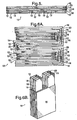
- FIG. 1 shows a front view, and Figure 2 shows a top view of such a multicell 10. While Figure 1 illustrates a multicell having five components of the cathode (five unicells), multicells with two, three, or four components of the cathode may be used, as well as multicells with greater than five components of the cathode, as previously described.
- Negative current collectors 18 are positioned in the anode 12 thereby splitting the anode 12 into two layers, as shown, and positive current collectors 20 are positioned in each of the multiple cathodes 16 thereby splitting each cathode 16 into two layers, as shown.
- the multicell depicted in Figures 1 and 2 may alternatively be in a zig-zag or folded configuration, with Figure 3A showing a top view and Figure 3B showing a perspective view.
- the multiple cathodes 16 are configured so that the parallel surfaces of the separator layer 14 separate the continuously configured anode 12 from two discontinuously configured cathodes 16.
- the multiple cathodes 16, being discontinuous, thus do not assume the zig-zag configuration.
- Positive current collectors 20 are located in each of the multiple cathodes 16, thereby splitting each cathode 16 into two layers, as shown.
- FIG. 4 An alternative embodiment of the invention, shown in Figures 4 , 5, 6A and 6B , is a multicell 10 design having a single cathode 16 (positive electrode) configured as the exterior of the folded cell 10, a separator 14, and multiple anodes 12 (negative electrodes) configured in the interior or inner surface of the cell 10. That is, a separator 14 separates a single cathode 16 from multiple anodes 12.
- Figure 4 shows a front view
- Figure 5 shows a top view of such a cell 10.
- Positive current collectors 20 are positioned in the cathode 16 thereby splitting the cathode 16 into two layers, as shown
- negative current collectors 18 are positioned in each of the multiple anodes 12 thereby splitting each anode 12 into two layers, as shown.
- the multicell depicted in Figures 4 and 5 may alternatively be in a zig-zag or folded configuration, with Figure 6A showing a top view and Figure 6B showing a perspective view.
- the multiple anodes 12 are configured so that the parallel surfaces of the separator layer 14 separate the continuously configured cathode 15 from two discontinuously configured anodes 12.
- the multiple anodes 12, being discontinuous, thus do not assume the zig-zag configuration.
- Negative current collectors 18 are located in each of the multiple anodes 12, thereby splitting each anode 12 into two layers.
- Another embodiment of the invention is a multibicell where the electrode forming the outermost layer of the final cell is configured discontinuously.
- a bicell components are adhered so that a pair of electrodes having the same charge sandwich one electrode having the opposite charge.
- Any or all of the electrodes may be comprised of a plurality of layers.
- each anode in the pair of anodes negative electrodes
- the cathode may have a positive current collector positioned therein, thereby splitting the cathode into two layers.
- One of the anode pair is located above, and the other of the anode pair is located below, the cathode.
- the anodes are in a discontinuous configuration. Each anode is separated from the cathode by a separator.
- All components i.e., the two pairs of anode layers sandwiching the cathode layers, current collectors, and separator adhered to form a bicell, and the plurality of bicells
- adherence may be by laminating using pressure (manual and/or mechanical), heat, or a combination of pressure and heat.
- a single adherence process controlled by a single thermal management system, can be used as known to one skilled in the art, for example, for charge voltage and discharge voltage.
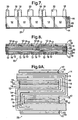
- Figures 7, 8, 9A and 9B are multibicell 22 designs having a single cathode 16 (positive electrode) configured in the interior of the folded cell 10, a pair of separators 14, and a pair of discontinuous anodes 12 (negative electrodes) as the outermost electrodes. That is, one separator 14 separates a single cathode 16 on one side from two anodes 12, and another separator 14 separates the single cathode 16 on the other side from two anodes 12.
- Figure 7 shows a front view
- Figure 8 shows a top view of such a multibicell 22.
- Figure 7 illustrates a multibicell 22 having five components of the anode 12 (five bicells), multibicells with two, three, or four components of the anode may be used, as well as multibicells with greater than five components of the anode, as previously described.
- a single positive current collector 20 is positioned in the cathode 16, thereby splitting the cathode 16 into a pair of cathode layers 16.
- a plurality of negative current collectors 18 are positioned in each of the multiple anodes 12, thereby splitting each of the multiple anodes 12 into a pair of anode layers 12.
- the multibicell 22 depicted in Figures 7 and 8 may be in a zig-zag or folded configuration, with Figure 9A showing a top view and Figure 9B showing a perspective view.
- the multiple anodes 12 are configured so that each of the parallel surfaces of the separator layer 14 separate the continuously configured cathode 16 from two discontinuously configured anodes 12.
- Negative current collectors 18 are located in each of the multiple anodes 12, thereby splitting each of the multiple anodes 12 into two anode layers 12, and positive current collectors 20 are located throughout the geometry of the cathodes 16, thereby splitting the cathodes 16 into two cathode layers 16.
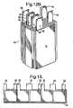
- Figures 10 , 11 , 12A and 12B show bicell 22 configurations which parallel those shown in Figures 7, 8, 9A and 9B , respectively, except for the identity of the electrode.
- Figures 10 and 11 in front view and top view, respectively, show two discontinuous cathodes 16 (as pairs of two cathode layers 16) sandwiching a single continuous anode 12 (as two anode layers 12).
- Figures 12A and 12B show the multibicell 22 in a zig-zag or folded configuration.
- Figure 12A shows a top view
- Figure 12B shows a perspective view.
- any of the above-described cells may include embodiments in which a current collector is on the outermost surface of an electrode.
- the current collector does not split the electrode into two layers.
- an anode may be separated from a cathode by a separator layer, with the negative current collector on the exterior surface of the anode, and/or the positive current collector on the exterior surface of the cathode.
- Discontinuous and continuous electrode configurations of this embodiment are shown in the following figures.
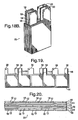
- Figures 13 , 14, 15A and 15B are multicell designs having current collectors external to a single anode 12 (negative electrode) configured as the outermost electrode in a folded cell 10, a separator 14, and multiple cathodes 16 (positive electrodes) configured as inner electrodes in a folded cell 10. That is, a separator 14 separates a single anode 12 from multiple cathodes 16.
- Figure 13 shows a front view
- Figure 14 shows a top view of such a cell 10.
- a single negative current collector 18 is positioned external to the anode 12 throughout the entire geometry.
- a plurality of positive current collectors 20 are positioned external to each of the multiple cathodes 16 throughout the entire geometry.
- the cell 10 depicted in Figures 13 and 14 may be in a zig-zag or folded configuration, with Figure 15A showing a top view and Figure 15B showing a perspective view.
- the multiple cathodes 16 are configured so that the facing parallel surfaces of the separator layers 14 separate the continuously configured anode 12 from two discontinuously configured cathodes 16, and the two discontinuously configured cathodes 16 with external current collectors 20 are mirror images.
- the multiple cathodes 16, being discontinuous, thus do not assume the zig-zag configuration.
- Figures 16, 17, 18A and 18B show multicells having external current collectors which parallel those shown in Figures 13 , 14, 15A and 15B , respectively, except for the charge of the electrode.
- Figure 16 shows a front view
- Figure 17 shows a top view, of a positive current collector 20 located external to a single cathode 16 (positive electrode), a separator 14, and multiple anodes 12 (negative electrodes) with a negative current collector 18 located external to each of the multiple anodes 12.
- the multiple anodes 12 are configured so that the facing parallel surfaces of the separator layers 14 separate the continuously configured cathode 16 from two discontinuously configured anodes 12, and the two discontinuously configured anodes 12 with external current collectors 18 are mirror images.
- Figures 18A and 18B show a folded or zig-zag configuration, with Figure 18A showing a top view, and Figure 18B showing a perspective view.
- the positive current collector 20 is located external to the cathode 16 throughout the entire geometry.
- Figures 19, 20 , 21A and 21B are multibicell 22 designs.
- a single cathode 16 (positive electrode) is configured in the interior of the folded cell 10, and the cathode 16 is split into two cathode layers 16 by a positive current collector 20.
- a pair of separators 14 separates each of the cathode layers 16 from a pair of discontinuous anodes 12 (negative electrodes). That is, one separator 14 separates one cathode layer 16 on one side from two anodes 12, and another separator 14 separates the other cathode layer 16 on the other side from two anodes 12.
- Each anode 12 has an external current collector 18.
- Figure 19 shows a front view
- Figure 20 shows a top view of such a multibicell 22. While Figure 19 illustrates a multibicell 22 having five components of the anode 12 (five bicells), multibicells with two, three, or four components of the anode 12 may be used, as well as multibicells with greater than five components of the anode 12, as previously described.
- the multibicell 22 depicted in Figures 19 and 20 may be in a zig-zag or folded configuration, with Figure 21A showing a top view and Figure 21B showing a perspective view.
- the multiple anodes 12 are configured so that each of the parallel surfaces of the separator layer 14 separate the continuously configured cathode layers 16 from two discontinuously configured anodes 12.
- Negative current collectors 18 are located external to each of the anodes 12, and form the outermost surface of the folded cell, as shown in Figure 21B .
- the multiple anodes 12 are configured so that each of the parallel surfaces of the separator layer 14 separate the continuously configured cathode 16 from two discontinuously configured anodes 12.
- Figures 22, 23, 24A and 24B show multibicell 22 configurations which parallel those shown in Figures 19, 20 , 21A and 21B , respectively, except for the charge of the electrode.
- a single anode 12 (negative electrode) is configured in the interior of the folded cell 10, and the anode 12 is split into two anode layers 12 by a negative current collector 18.
- a pair of separators 14 separates each of the anode layers 12 from a pair of discontinuous cathodes 16 (positive electrodes). That is, one separator 14 separates one anode layer 12 on one side from two cathodes 16, and another separator 14 separates the other anode layer 12 on the other side from two cathodes 16.
- Each cathode 16 has an external current collector 20.
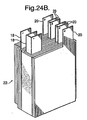
- the multibicell 22 depicted in Figures 22 and 23 may be in a zig-zag or folded configuration, with Figure 24A showing a top view and Figure 24B showing a perspective view.
- the multiple cathodes 16 are configured so that each of the parallel surfaces of the separator layer 14 separate the continuously configured anode layers 12 from two discontinuously configured cathodes 16.
- Positive current collectors 20 are located external to each of the cathodes 16, and form the outermost surface of the folded cell, as shown in Figure 24B .
- a cell having at least one continuous electrode and two discontinuous electrodes where either the anode is the continuous electrode and the cathodes are the discontinuous electrodes, or the cathode is the continuous electrode and the anodes are the discontinuous electrodes, any of the following embodiments of a cell are possible: the cell may be a multicell ( Figures 1-6 ; Figures 13-18 ) or a multibicell ( Figures 7-12 ; Figures 19-24 ).
- the cell may have one anode and one cathode with a current collector between the anode and the cathode, or the cell may have two anodes separated by a negative current collector between the anodes, thereby splitting the anode into two anode layers, and/or the cell may have two cathodes separated by a positive current collector between the cathodes, thereby splitting the cathode into two cathode layers.
- both negative and positive current collectors may be on the outer surface of the respective anode and cathode ( Figures 13 , 14, and 15 ).
- negative current collectors may be on the outer surface of the anodes and positive current collectors may be between a single cathode, thus splitting the cathode into two layers the two cathodes ( Figures 19, 20 , and 21 ), or positive current collectors may be on the outer surface of the cathodes, and negative current collectors may be between a single anode, thus splitting the anode into two anode layers ( Figures 22, 23 , and 24 ).
Landscapes
- Chemical & Material Sciences (AREA)
- Engineering & Computer Science (AREA)
- Chemical Kinetics & Catalysis (AREA)
- Electrochemistry (AREA)
- General Chemical & Material Sciences (AREA)
- Manufacturing & Machinery (AREA)
- Materials Engineering (AREA)
- Physics & Mathematics (AREA)
- Condensed Matter Physics & Semiconductors (AREA)
- Dispersion Chemistry (AREA)
- General Physics & Mathematics (AREA)
- Inorganic Chemistry (AREA)
- Secondary Cells (AREA)
- Battery Electrode And Active Subsutance (AREA)
Description
- This invention relates to a method of preparation of lithium cells, in particular lithium ion and lithium ion polymer batteries.
- Lithium ion cells and batteries are secondary (i.e., rechargeable) energy storage devices well known in the art. The lithium ion cell, known also as a rocking chair type lithium ion battery, typically comprises essentially a carbonaceous anode (negative electrode) that is capable of intercalating lithium ions, a lithium-retentive cathode (positive electrode) that is also capable of intercalating lithium ions, and a non-aqueous, lithium ion conducting electrolyte therebetween.
- The carbon anode comprises any of the various types of carbon (e.g., graphite, coke, carbon fiber, etc.) which are capable of reversibly storing lithium species, and which are bonded to an electrochemically conductive current collector (e.g. copper foil, grid, or mesh) by means of a suitable organic binder (e.g., polyvinylidene fluoride, PVdF).
- The cathode comprises such materials as transition metal chalcogenides that are bonded to an electrochemically conductive current collector (e.g., aluminum foil, grid, or mesh) by a suitable organic binder. Chalcogenide compounds include oxides, sulfides, selenides, and tellurides of such metals as vanadium, titanium, chromium, copper, molybdenum, niobium, iron, nickel, cobalt and manganese. Lithiated transition metal oxides are at present the preferred positive electrode intercalation compounds. Examples of suitable cathode materials include LiMnO2 LiCoO2 LiNiO2 and LiFePO4 their solid solutions and/or their combination with other metal oxides and dopant elements, e.g., titanium, magnesium, aluminum, boron, etc.
- The electrolyte in such lithium ion cells comprises a lithium salt dissolved in a non-aqueous solvent which may be (1) completely liquid, (2) an immobilized liquid (e.g., gelled or entrapped in a polymer matrix), or (3) a pure polymer. Known polymer matrices for entrapping the electrolyte include polyacrylates, polyurethanes, polydialkylsiloxanes, polymethacrylates, polyphosphazenes, polyethers, polyvinylidene fluoride, polyolefins such as polypropylene and polyethylene, and polycarbonates, and may be polymerized in situ in the presence of the electrolyte to trap the electrolyte therein as the polymerization occurs. Known polymers for pure polymer electrolyte systems include polyethylene oxide (PEO), polymethylene-polyethylene oxide (MPEO), or polyphosphazenes (PPE). Known lithium salts for this purpose include, for example, LiPF6, LiClO4, LiSCN, LiAlCl4, LiBF4, LiN(CF3SO2)2, LiCF3SO3, LiC(SO2CF3)3, LiO3SCF2CF3, LiC6F5SO3, LiO2CF3, LiAsF6, and LiSbF6. Known organic solvents for the lithium salts include, for example, alkylcarbonates (e.g., propylene carbonate, ethylene carbonate), dialkyl carbonates, cyclic ethers, cyclic esters, glymes, lactones, formates, esters, sulfones, nitrites, and oxazolidinones. The electrolyte is incorporated into pores in a separator layer between the cathode and anode. The separator may be glass mat, for example, containing a small percentage of a polymeric material, or may be any other suitable ceramic or ceramic/polymer material. Silica is a typical main component of the separator layer.
- During processing of the cell precursor, a large quantity of a homogeneously distributed plasticizer is present in the solid polymeric matrix in order to create porosity. For example, the plasticizer may be propylene carbonate, phthalic acid diesters, adipic acid diesters, acetic acid esters, organic phosphates, and/or trimellitic acid triesters. These plasticizers must be removed before the cell is activated with an electrolyte because, if mixed with the electrolyte, the plasticizers can damage the cell. The plasticizers are generally removed by extracting them into a solvent, such as diethyl ether or hexane, which selectively extract the plasticizer without significantly affecting the polymer matrix. This produces a "dry" electrolytic cell precursor, in that the precursor does not contain any electrolyte solvent or salt. An electrolyte solvent and electrolyte salt solution is then imbibed into the "dry" electrolytic cell copolymer membrane structure to yield a functional electrolytic cell system. The ion-conducting electrolyte provides ion transfer from one electrode to the other, and commonly permeates the porous structure of each of the electrodes and the separator.
- Lithium and lithium ion polymer cells are often made by adhering, e.g., by laminating, thin films of the anode, cathode and/or electrolyte/separator together. Each of these components is individually prepared, for example, by coating, extruding, or otherwise, from compositions including one or more binder materials and a plasticizer. The electrolyte/separator is adhered to an electrode (anode or cathode) to form a subassembly, or is adheringly sandwiched between the anode and cathode layers to form an individual cell or unicell. A second electrolyte/separator and a second corresponding electrode may be adhered to form a bicell of, sequentially, a first counter electrode, a film separator, a central electrode, a film separator, and a second counter electrode. A number of cells are adhered and bundled together to form a high energy/voltage battery or multicell.
- In constructing a lithium-ion cell, an anodic current collector may be positioned adjacent a single anode film, or sandwiched between two separate anode films, to form the negative electrode. Similarly, a cathodic current collector may be positioned adjacent a single cathode film, or sandwiched between two separate cathode films, to form the positive electrode. A separator is positioned between the negative electrode and the positive electrode. The anode, separator, and cathode structures are then adhered together (e.g., by laminating) to produce a unitary flexible electrolytic cell precursor.
- Depending upon the cell, physical manipulations may be problematic. For example, a cell having a plurality of layers may be bulky, may not bundle tightly, and/or may not bundle uniformly. As a result, the cell may not have the desired physical and performance properties. There is thus a need for methods to enhance processing and performance efficiency that will provide advantages, such as improved productivity and decreased costs.
- Lithium polymer batteries comprising opposite electrodes, a separator and an electrolyte are known from the documents J. Power Sources 54, 163 (1995) and 68, 432 (1997), as well as the documents SAE World Congress 1 (2001) and Telekomm. Energy Conf. 656 (1998).
US 4,916,036 discloses a continuous anode for a lithium cell andUS 5,498,489 discloses a stacked rechargeable lithium battery assembly with a laminated polymer electrolyte configuration.JP-05129025 A - The present invention provides a lithium polymer battery comprising at least one cell, said cell comprising a first electrode, a second electrode of opposite charge from the first electrode, and a separator between the first and second electrodes, the first electrode configured continuously and the second electrode configured discontinuously. The cell may be configured as a multicell or a multibicell. The battery may contain a current collector for at least one of the electrodes, either on an outer or inner surface of an electrode, or between layers or films of electrodes having the same charge.
- The present invention also provides a lithium polymer battery comprising at least one cell with a first electrode, a second electrode of opposite charge from the first electrode, and a separator between the first and second electrodes, the battery in a corrugated configuration. In the corrugated configuration the first electrode is in the interior of a folded cell and is configured discontinuously, and the second electrode is the exterior electrode of a folded cell and is configured continuously. The battery may also comprise a current collector for at least one of the electrodes. The current collector may be on an outer surface of the exterior electrode and configured continuously, or it may be on an outer surface of the inner electrode and configured discontinuously, or it may be between layers or films of electrodes having the same charge.
- The present invention also provides a method for preparing a lithium polymer cell. The method comprises (a) providing a first electrode configured continuously, second electrodes configured discontinuously, and a separator between the first and second electrodes, and (b) adhering the separator to the first and second electrodes to form a cell, such as a multicell or a multibicell. The method may further include folding the cell at the junctures of the discontinuous electrodes with the discontinuous electrodes on the interior of the cell. The method may also comprise repeating steps (a) and (b) to form a plurality of cells and adhering the plurality of cells to form a battery, and folding the battery at the junctures of the discontinuous electrodes with the discontinuous electrodes on the interior of the battery. The cells may be adhered in a single process, and the process may be controlled by a thermal management system.
- There is thus provided a lithium cell that provides enhanced processing and performance efficiency, and a method of manufacturing the cell with greater productivity and decreased costs.
- The present invention will now be described, by way of example, with reference to the accompanying drawings, in which:
-
Figure 1 is a diagrammatic illustration of a front view of one embodiment of a cell having one anode and multiple cathodes. -
Figure 2 is a diagrammatic illustration of a top view of the embodiment of the cell shown inFigure 1 . -
Figure 3A is a diagrammatic top view of the folded cell shown inFigure 1 . -
Figure 3B is a perspective view of the folded cell shown inFigure 1 .Figure 4 is a diagrammatic illustration of an alternative embodiment of a cell having one cathode and multiple anodes. -
Figure 5 is a diagrammatic illustration of a top view of the embodiment of the cell shown inFigure 4 . -
Figure 6A is a diagrammatic top view of the folded cell shown inFigure 4 . -
Figure 6B is a perspective view of the folded cell shown inFigure 4 . -
Figure 7 is a diagrammatic illustration of a front view of one embodiment of a cell having one cathode and multiple anodes. -
Figure 8 is a diagrammatic illustration of a top view of the embodiment of the cell shown inFigure 7 . -
Figure 9A is a diagrammatic top view of the folded cell shown inFigure 7 . -
Figure 9B is a perspective view of the folded cell shown inFigure 7 . -
Figure 10 is a diagrammatic illustration of a front view of an alternative embodiment of a cell having one anode and multiple cathodes. -
Figure 11 is a diagrammatic illustration of a top view of the embodiment of the cell shown inFigure 10 . -
Figure 12A is a diagrammatic top view of the folded cell shown inFigure 10 . -
Figure 12B is a perspective view of the folded cell shown inFigure 10 . -
Figure 13 is a diagrammatic illustration of a front view of one embodiment of a cell with an outside current collector and having one anode and multiple cathodes. -
Figure 14 is a diagrammatic illustration of a top view of the embodiment of the cell shown inFigure 13 . -
Figure 15A is a diagrammatic top view of the folded cell shown inFigure 13 . -
Figure 15B is a perspective view of the folded cell shown inFigure 13 . -
Figure 16 is a diagrammatic illustration of a front view of an alternative embodiment of a cell with an outside current collector and having one cathode and multiple anodes. -
Figure 17 is a diagrammatic illustration of a top view of the embodiment of the cell shown inFigure 16 . -
Figure 18A is a diagrammatic top view of the folded cell shown inFigure 16 . -
Figure 18B is a perspective view of the folded cell shown inFigure 16 . -
Figure 19 is a diagrammatic illustration of a front view of one embodiment of a cell with an outside current collector and having one cathode and multiple anodes. -
Figure 20 is a diagrammatic illustration of a top view of the embodiment of the cell shown inFigure 19 . -
Figure 21A is a diagrammatic top view of the folded cell shown inFigure 19 . -
Figure 21B is a perspective view of the folded cell shown inFigure 19 . -
Figure 22 is a diagrammatic illustration of a front view of one embodiment of a cell with an outside current collector and having one anode and multiple cathodes. -
Figure 23 is a diagrammatic illustration of an alternative embodiment of the cell shown inFigure 22 . -
Figure 24A is a diagrammatic top view of the folded cell shown inFigure 22 . -
Figure 24B is a perspective view of the folded cell shown inFigure 22 . - An electrode cell has two opposite electrodes, an anode (negative electrode) and cathode (positive electrode), with a separator between them. Each electrode (the anode and/or the cathode) may be comprised of two or more layers that are separated by a current collector. For example, an anode may be comprised of two negative electrode layers separated by a negative current collector, and/or the cathode may be comprised of two positive electrode layers separated by a positive current collector. The plane of the current collector is generally parallel to the plane of the polymer matrix film portion of the electrode. Similarly, the plane of separator films is generally parallel to the plane of the electrodes.
- The electrodes and separator are adhered to form a cell. As known to one skilled in the art, adherence may be by laminating using pressure (manual and/or mechanical), heat, or a combination of pressure and heat. When the components are adhered or laminated, there is a series of generally planar laminated elements. The number of layers may make cell configurations difficult, particularly in relation to achieving a desired configuration. As used herein, cell configurations refer to the result of physical manipulations of the adhered layers that are performed to achieve a compact functional cell, and include folding, rolling, shaping, etc. The battery may be shaped into folds of parallel and alternating ridges and grooves, with a resulting corrugated structure. Positive and negative terminals, also referred to as tabs, are used to establish or break the electrical connection of the cell.
- Various designs are contemplated to configure a cell in which one electrode is continuous, while the other electrode is discontinuous. More specifically, the electrode that will be the outermost electrode of the final cell, either the anode or the cathode, is configured as continuous. The opposite electrode is configured as discontinuous. For example, a cell designed with a discontinuous inner negative electrode will have a continuous outer positive electrode, and a cell designed with a discontinuous inner positive electrode will have a continuous outer negative electrode. As used herein, discontinuous is defined as an anode or cathode in which the charge of that electrode, either positive or negative, is carried by a plurality of joined electrodes or multiple joined electrodes, rather than by a single electrode. Thus, as used herein, multiple electrodes refer to discontinuous electrodes or components, and a single electrode refers to a continuous electrode.
- The number of discontinuous electrodes or components, making up the inner electrode, depends upon the parameters desired in the resulting cell (e.g., size, power, efficiency), as determined by one skilled in the art. The inventive cell configurations, and methods for producing these cell configurations, allow for increased flexibility in battery design. The cell configurations can be used to produce a battery of any size or capacity, for example, a multibicell battery, a multicell battery, a battery having multiple modules that each have multiple multicells or multibicells, etc.
- The inventive cell configurations, and method for preparing the cell configurations, provide several desirable features. They allow uniformity in the structure and performance of multicell batteries. The batteries thus configured have continuous adherence of the middle as well as the external or final cell electrodes (both multicell and multibicell). This advantageously results in improved cell capacity, life cycle, and power. The normal loss of the first charge/discharge cycle of the cell is also reduced or eliminated, because the inventive design improves uniformity of battery charge and discharge. Impedence of every individual cell or bicell is equal, with the same voltage and same capacity.
- One embodiment of the invention, shown in
Figures 1, 2, 3A and3B , is a multicell 10 design having a single anode 12 (negative electrode) configured as the exterior of the foldedcell 10, aseparator 14, and multiple cathodes 16 (positive electrodes) configured in the interior or inner surface of thecell 10. That is, aseparator 14 separates asingle anode 12 frommultiple cathodes 16.Figure 1 shows a front view, andFigure 2 shows a top view of such a multicell 10. WhileFigure 1 illustrates a multicell having five components of the cathode (five unicells), multicells with two, three, or four components of the cathode may be used, as well as multicells with greater than five components of the cathode, as previously described. Negativecurrent collectors 18 are positioned in theanode 12 thereby splitting theanode 12 into two layers, as shown, and positivecurrent collectors 20 are positioned in each of themultiple cathodes 16 thereby splitting eachcathode 16 into two layers, as shown. - The multicell depicted in
Figures 1 and 2 may alternatively be in a zig-zag or folded configuration, withFigure 3A showing a top view andFigure 3B showing a perspective view. In this embodiment, there is asingle anode 12 with a negativecurrent collector 18 located throughout the entire geometry, thereby splitting theanode 12 into two layers, as shown. Themultiple cathodes 16 are configured so that the parallel surfaces of theseparator layer 14 separate the continuously configuredanode 12 from two discontinuously configuredcathodes 16. Themultiple cathodes 16, being discontinuous, thus do not assume the zig-zag configuration. Positivecurrent collectors 20 are located in each of themultiple cathodes 16, thereby splitting eachcathode 16 into two layers, as shown. - An alternative embodiment of the invention, shown in
Figures 4 ,5, 6A and 6B , is a multicell 10 design having a single cathode 16 (positive electrode) configured as the exterior of the foldedcell 10, aseparator 14, and multiple anodes 12 (negative electrodes) configured in the interior or inner surface of thecell 10. That is, aseparator 14 separates asingle cathode 16 frommultiple anodes 12.Figure 4 shows a front view, andFigure 5 shows a top view of such acell 10. Positivecurrent collectors 20 are positioned in thecathode 16 thereby splitting thecathode 16 into two layers, as shown, and negativecurrent collectors 18 are positioned in each of themultiple anodes 12 thereby splitting eachanode 12 into two layers, as shown. - The multicell depicted in
Figures 4 and5 may alternatively be in a zig-zag or folded configuration, withFigure 6A showing a top view andFigure 6B showing a perspective view. In this embodiment, there is asingle cathode 16 with a positivecurrent collector 20 located throughout the entire geometry, thereby splitting thecathode 16 into two layers. Themultiple anodes 12 are configured so that the parallel surfaces of theseparator layer 14 separate the continuously configured cathode 15 from two discontinuously configuredanodes 12. Themultiple anodes 12, being discontinuous, thus do not assume the zig-zag configuration. Negativecurrent collectors 18 are located in each of themultiple anodes 12, thereby splitting eachanode 12 into two layers. - Another embodiment of the invention is a multibicell where the electrode forming the outermost layer of the final cell is configured discontinuously. In a bicell, components are adhered so that a pair of electrodes having the same charge sandwich one electrode having the opposite charge. Any or all of the electrodes may be comprised of a plurality of layers. For example, each anode in the pair of anodes (negative electrodes) may have a negative current collector therebetween, thereby splitting each anode of each pair into two layers. The cathode may have a positive current collector positioned therein, thereby splitting the cathode into two layers. One of the anode pair is located above, and the other of the anode pair is located below, the cathode. The anodes are in a discontinuous configuration. Each anode is separated from the cathode by a separator.
- All components (i.e., the two pairs of anode layers sandwiching the cathode layers, current collectors, and separator adhered to form a bicell, and the plurality of bicells) are joined or adhered to form a multibicell. As previously described, adherence may be by laminating using pressure (manual and/or mechanical), heat, or a combination of pressure and heat. Advantageously, a single adherence process, controlled by a single thermal management system, can be used as known to one skilled in the art, for example, for charge voltage and discharge voltage.
-
Figures 7, 8, 9A and9B are multibicell 22 designs having a single cathode 16 (positive electrode) configured in the interior of the foldedcell 10, a pair ofseparators 14, and a pair of discontinuous anodes 12 (negative electrodes) as the outermost electrodes. That is, oneseparator 14 separates asingle cathode 16 on one side from twoanodes 12, and anotherseparator 14 separates thesingle cathode 16 on the other side from twoanodes 12.Figure 7 shows a front view, andFigure 8 shows a top view of such amultibicell 22. WhileFigure 7 illustrates amultibicell 22 having five components of the anode 12 (five bicells), multibicells with two, three, or four components of the anode may be used, as well as multibicells with greater than five components of the anode, as previously described. - A single positive
current collector 20 is positioned in thecathode 16, thereby splitting thecathode 16 into a pair of cathode layers 16. A plurality of negativecurrent collectors 18 are positioned in each of themultiple anodes 12, thereby splitting each of themultiple anodes 12 into a pair of anode layers 12. - The
multibicell 22 depicted inFigures 7 and 8 may be in a zig-zag or folded configuration, withFigure 9A showing a top view andFigure 9B showing a perspective view. In this embodiment, there is asingle cathode 16 with a positivecurrent collector 20 located throughout the entire geometry, thereby splitting thecathodes 16 into two cathode layers 16. Themultiple anodes 12 are configured so that each of the parallel surfaces of theseparator layer 14 separate the continuously configuredcathode 16 from two discontinuously configuredanodes 12. Themultiple anodes 12, being discontinuous, thus do not assume the zig-zag configuration. Negativecurrent collectors 18 are located in each of themultiple anodes 12, thereby splitting each of themultiple anodes 12 into twoanode layers 12, and positivecurrent collectors 20 are located throughout the geometry of thecathodes 16, thereby splitting thecathodes 16 into two cathode layers 16. -
Figures 10 ,11 ,12A and12B show bicell 22 configurations which parallel those shown inFigures 7, 8, 9A and9B , respectively, except for the identity of the electrode.Figures 10 and11 , in front view and top view, respectively, show two discontinuous cathodes 16 (as pairs of two cathode layers 16) sandwiching a single continuous anode 12 (as two anode layers 12).Figures 12A and12B show themultibicell 22 in a zig-zag or folded configuration.Figure 12A shows a top view, andFigure 12B shows a perspective view. - Any of the above-described cells may include embodiments in which a current collector is on the outermost surface of an electrode. In these embodiments, the current collector does not split the electrode into two layers. For example, an anode may be separated from a cathode by a separator layer, with the negative current collector on the exterior surface of the anode, and/or the positive current collector on the exterior surface of the cathode. Discontinuous and continuous electrode configurations of this embodiment are shown in the following figures.
-
Figures 13 ,14, 15A and 15B are multicell designs having current collectors external to a single anode 12 (negative electrode) configured as the outermost electrode in a foldedcell 10, aseparator 14, and multiple cathodes 16 (positive electrodes) configured as inner electrodes in a foldedcell 10. That is, aseparator 14 separates asingle anode 12 frommultiple cathodes 16.Figure 13 shows a front view, andFigure 14 shows a top view of such acell 10. A single negativecurrent collector 18 is positioned external to theanode 12 throughout the entire geometry. A plurality of positivecurrent collectors 20 are positioned external to each of themultiple cathodes 16 throughout the entire geometry. - The
cell 10 depicted inFigures 13 and14 may be in a zig-zag or folded configuration, withFigure 15A showing a top view andFigure 15B showing a perspective view. In this embodiment, there is asingle anode 12 with a negativecurrent collector 18 located external to theanode 12 throughout the entire geometry. Themultiple cathodes 16 are configured so that the facing parallel surfaces of the separator layers 14 separate the continuously configuredanode 12 from two discontinuously configuredcathodes 16, and the two discontinuously configuredcathodes 16 with externalcurrent collectors 20 are mirror images. Themultiple cathodes 16, being discontinuous, thus do not assume the zig-zag configuration. -
Figures 16, 17, 18A and18B show multicells having external current collectors which parallel those shown inFigures 13 ,14, 15A and 15B , respectively, except for the charge of the electrode.Figure 16 shows a front view, andFigure 17 shows a top view, of a positivecurrent collector 20 located external to a single cathode 16 (positive electrode), aseparator 14, and multiple anodes 12 (negative electrodes) with a negativecurrent collector 18 located external to each of themultiple anodes 12. Themultiple anodes 12 are configured so that the facing parallel surfaces of the separator layers 14 separate the continuously configuredcathode 16 from two discontinuously configuredanodes 12, and the two discontinuously configuredanodes 12 with externalcurrent collectors 18 are mirror images. Themultiple anodes 16, being discontinuous, thus do not assume the zig-zag configuration.Figures 18A and18B show a folded or zig-zag configuration, withFigure 18A showing a top view, andFigure 18B showing a perspective view. As shown inFigures 18A and18B , the positivecurrent collector 20 is located external to thecathode 16 throughout the entire geometry. -
Figures 19, 20 ,21A and 21B are multibicell 22 designs. A single cathode 16 (positive electrode) is configured in the interior of the foldedcell 10, and thecathode 16 is split into twocathode layers 16 by a positivecurrent collector 20. A pair ofseparators 14 separates each of the cathode layers 16 from a pair of discontinuous anodes 12 (negative electrodes). That is, oneseparator 14 separates onecathode layer 16 on one side from twoanodes 12, and anotherseparator 14 separates theother cathode layer 16 on the other side from twoanodes 12. Eachanode 12 has an externalcurrent collector 18. -
Figure 19 shows a front view, andFigure 20 shows a top view of such amultibicell 22. WhileFigure 19 illustrates amultibicell 22 having five components of the anode 12 (five bicells), multibicells with two, three, or four components of theanode 12 may be used, as well as multibicells with greater than five components of theanode 12, as previously described. - The
multibicell 22 depicted inFigures 19 and 20 may be in a zig-zag or folded configuration, withFigure 21A showing a top view andFigure 21B showing a perspective view. In this embodiment, there is asingle cathode 16 with a positivecurrent collector 20 located internal to thecathode 16 throughout the entire geometry, thereby splitting thecathode 16 into two cathode layers 16. Themultiple anodes 12 are configured so that each of the parallel surfaces of theseparator layer 14 separate the continuously configured cathode layers 16 from two discontinuously configuredanodes 12. Theanodes 12, being discontinuous, thus do not assume the zig-zag configuration. Negativecurrent collectors 18 are located external to each of theanodes 12, and form the outermost surface of the folded cell, as shown inFigure 21B . Themultiple anodes 12 are configured so that each of the parallel surfaces of theseparator layer 14 separate the continuously configuredcathode 16 from two discontinuously configuredanodes 12. Themultiple anodes 12, being discontinuous, thus do not assume the zig-zag configuration. -
Figures 22, 23, 24A and24B show multibicell 22 configurations which parallel those shown inFigures 19, 20 ,21A and 21B , respectively, except for the charge of the electrode. A single anode 12 (negative electrode) is configured in the interior of the foldedcell 10, and theanode 12 is split into twoanode layers 12 by a negativecurrent collector 18. A pair ofseparators 14 separates each of the anode layers 12 from a pair of discontinuous cathodes 16 (positive electrodes). That is, oneseparator 14 separates oneanode layer 12 on one side from twocathodes 16, and anotherseparator 14 separates theother anode layer 12 on the other side from twocathodes 16. Eachcathode 16 has an externalcurrent collector 20. - The
multibicell 22 depicted inFigures 22 and 23 may be in a zig-zag or folded configuration, withFigure 24A showing a top view andFigure 24B showing a perspective view. In this embodiment, there is asingle anode 12 with a negativecurrent collector 18 located internal to theanode 12 throughout the entire geometry, thereby splitting theanode 12 into two anode layers 12. Themultiple cathodes 16 are configured so that each of the parallel surfaces of theseparator layer 14 separate the continuously configured anode layers 12 from two discontinuously configuredcathodes 16. Thecathodes 16, being discontinuous, thus do not assume the zig-zag configuration. Positivecurrent collectors 20 are located external to each of thecathodes 16, and form the outermost surface of the folded cell, as shown inFigure 24B . With a cell having at least one continuous electrode and two discontinuous electrodes, where either the anode is the continuous electrode and the cathodes are the discontinuous electrodes, or the cathode is the continuous electrode and the anodes are the discontinuous electrodes, any of the following embodiments of a cell are possible: the cell may be a multicell (Figures 1-6 ;Figures 13-18 ) or a multibicell (Figures 7-12 ;Figures 19-24 ). In either the multicell or multibicell embodiments, the cell may have one anode and one cathode with a current collector between the anode and the cathode, or the cell may have two anodes separated by a negative current collector between the anodes, thereby splitting the anode into two anode layers, and/or the cell may have two cathodes separated by a positive current collector between the cathodes, thereby splitting the cathode into two cathode layers. In a multibicell embodiment, both negative and positive current collectors may be on the outer surface of the respective anode and cathode (Figures 13 ,14, and 15 ). In a multibicell embodiment, negative current collectors may be on the outer surface of the anodes and positive current collectors may be between a single cathode, thus splitting the cathode into two layers the two cathodes (Figures 19, 20 , and21 ), or positive current collectors may be on the outer surface of the cathodes, and negative current collectors may be between a single anode, thus splitting the anode into two anode layers (Figures 22, 23 , and24 ). - While the present invention has been illustrated by the description of an embodiment thereof, and while the embodiment has been described in considerable detail, it is not intended to restrict or in any way limit the scope of the appended claims to such detail. Additional advantages and modifications will readily appear to those skilled in the art. The invention in its broader aspects is therefore not limited to the specific details, representative apparatus and method and illustrative examples shown and described. Accordingly, departures may be made from such details without departing from the scope or spirit of Applicant=s general inventive concept.
Claims (29)
- A lithium polymer battery comprising at least one cell 10, said cell 10 comprising a first electrode configured continuously, at least one second electrode of opposite charge from the first electrode configured discontinuously, and a separator 14 between the first and second electrodes.
- The battery of claim 1 wherein the cell 10 is selected from the group consisting of a multicell 10 and a multibicell 22.
- The battery of claim 1 wherein the cell 10 has a configuration selected from the group consisting of
at least one anode 12 and at least one cathode 16,
at least one anode 12 having a current collector positioned therein and at least one cathode,
at least one cathode having a current collector positioned therein and at least one anode 12, and
at least two anodes 12 and at least two cathodes 16, said anode 12 and cathodes 16 each having a current collector positioned therein. - The battery of claim 3 wherein said at least one anode 12 has an external current collector.
- The battery of claim 3 wherein said at least one cathode has an external current collector.
- The battery of claim 1 wherein the cell 10 is a multibicell 22 comprising an outer pair of two anode 12 layers with a negative current collector 18 between the anode 12 layers and an inner pair of two anode 12 layers with a negative current collector 18 between the anode 12 layers, and a cathode 16 comprising two cathode 16 layers with a positive current collector 20 between the cathode 16 layers, said cathode 16 between said outer pair of anodes 12 and said inner pair of anodes, said multibicell 22 further comprising a separator 14 between said outer pair of anodes 12 and said inner pair of anodes 12 and said cathode 16.
- The battery of claim 1 wherein the cell 10 is a multibicell 22 comprising an outer pair of two cathode 16 layers with a positive current collector 20 between the cathode 16 layers and an inner pair of two cathode 16 layers with a positive current collector 20 between the cathode 16 layers, and an anode 12 comprising two anode 12 layers with a negative current collector 18 between the anode 12 layers, said anode 12 between said outside pair of cathodes 16 and said inner pair of cathodes 16, said multibicell 22 further comprising a separator 14 between said outer pair of cathodes 16 and said inner pair of cathodes 16 and said anode 12.
- The battery of claim 1 further comprising a current collector for at least one of the electrodes.
- The battery of claim 8 wherein the current collector is aluminum foil, grid, or mesh for a positive electrode, and copper foil, grid, or mesh for a negative electrode.
- The battery of claim 8 wherein the current collector is on an outer surface of at least one electrode.
- The battery of claim 8 wherein the current collector is on an inner surface of at least one electrode.
- The battery of claim 8 wherein the current collector is positioned in at least one electrode to split the electrode into at least two layers.
- A lithium polymer battery comprising at least one cell 10, said cell 10 comprising a first electrode, at least one second electrode of opposite charge from the first electrode, and a separator 14 between the first and second electrodes, the battery in a corrugated configuration with the first electrode continuous and the second electrode discontinuous.
- The battery of claim 13 wherein the cell 10 is selected from the group consisting of a multicell 10 and a multibicell 22.
- The battery of claim 13 wherein the cell 10 is selected from the group consisting of
at least one anode 12 and at least one cathode 16,
at least one anode 12 having a current collector positioned therein and at least one cathode 16,
at least one cathode 16 having a current collector positioned therein and at least one anode 12, and
at least two anodes and at least two cathodes 16, said anodes and cathodes 16 each having a current collector positioned therein. - The battery of claim 13 wherein the cell 10 is a multibicell 22 comprising an outer pair of two anode 12 layers with a negative current collector 18 between the anode 12 layers and an inner pair of two anode 12 layers with a negative current collector 18 between the anode 12 layers, and a cathode 16 comprising two cathode 16 layers with a positive current collector 20 between the cathode 16 layers, said cathode 16 between said outer pair of anodes 12 and said inner pair of anodes 12, said multibicell 22 further comprising a separator 14 between said outer pair of anodes 12 and said inner pair of anodes 12 and said cathode 16.
- The battery of claim 13 wherein the cell 10 is a bicell 22 comprising an outer pair of two cathode 16 layers with a positive current collector 20 between the cathode 16 layers and an inner pair of cathode 16 layers with a positive current collector 20 between the cathode 16 layers, and an anode 12 comprising two anode 12 layers with a negative current collector 18 between the anode 12 layers, said anode 12 between said outer pair of cathodes 16 and said inner pair of cathodes 16, said multibicell 22 further comprising a separator 14 between said outer pair of cathodes 16 and said inner pair of cathodes 16 and said anode 12.
- The battery of claim 13 further comprising a current collector for at least one of the electrodes.
- The battery of claim 18 wherein the current collector is aluminum foil, grid, or mesh for a positive electrode, and copper foil, grid, or mesh for a negative electrode.
- The battery of claim 18 wherein the current collector is on an outer surface of the electrode and is configured continuously.
- The battery of claim 18 wherein the current collector is on an inner surface of the electrode and is configured discontinuously.
- A method for preparing a lithium polymer cell 10 comprising(a) providing a continuous electrode, at least two discontinuous electrodes, and a separator 14 between said continuous electrode and said discontinuous electrodes, and(b) adhering the separator 14 to the continuous and discontinuous electrodes to form a multicell 10.
- The method of claim 22 further comprising(c) configuring the multicell10 with the discontinuous electrodes in the interior of the multicell 10 and the continuous electrode at the exterior of the multicell 10.
- The method of claim 22 further comprising repeating steps (a) and (b) to form a plurality of multicells 22 and adhering the plurality of cells 10 to form a battery.
- The method of claim 24 further comprising(c) configuring the battery with the discontinuous electrodes in the interior of the battery and the continuous electrode at the exterior of the battery.
- The method of claim 22 wherein adhering the plurality of cells 10 is by a single process.
- The method of claim 26 wherein the adhering process is controlled by a thermal management system.
- The method of claim 23 wherein configuring is by a method selected from the group consisting of rolling, folding, bending, and combinations thereof.
- The method of claim 25 wherein configuring is by a method selected from the group consisting of rolling folding, bending, and combinations thereof.
Applications Claiming Priority (2)
| Application Number | Priority Date | Filing Date | Title |
|---|---|---|---|
| US348749 | 2003-01-22 | ||
| US10/348,749 US20040142235A1 (en) | 2003-01-22 | 2003-01-22 | Lithium polymer battery design |
Publications (2)
| Publication Number | Publication Date |
|---|---|
| EP1441409A1 EP1441409A1 (en) | 2004-07-28 |
| EP1441409B1 true EP1441409B1 (en) | 2011-04-13 |
Family
ID=32594916
Family Applications (1)
| Application Number | Title | Priority Date | Filing Date |
|---|---|---|---|
| EP04075112A Expired - Lifetime EP1441409B1 (en) | 2003-01-22 | 2004-01-16 | New configuration and lithium polymer battery design |
Country Status (3)
| Country | Link |
|---|---|
| US (1) | US20040142235A1 (en) |
| EP (1) | EP1441409B1 (en) |
| DE (1) | DE602004032189D1 (en) |
Families Citing this family (14)
| Publication number | Priority date | Publication date | Assignee | Title |
|---|---|---|---|---|
| CN1270400C (en) * | 2003-09-01 | 2006-08-16 | 比亚迪股份有限公司 | Columnar lithium ion secondary cell |
| US20050175902A1 (en) * | 2004-02-11 | 2005-08-11 | Mohammad Parsian | Lithium polymer battery cell |
| CN103069609A (en) * | 2010-08-24 | 2013-04-24 | 赛昂能源有限公司 | Electrically non-conductive materials for electrochemical cells |
| KR20120028750A (en) * | 2010-09-15 | 2012-03-23 | 임은석 | Printed circuit board and method of mounting electronic components |
| KR101332282B1 (en) | 2012-03-14 | 2013-11-22 | 주식회사 엘지화학 | Electrode Assembly of Novel Structure and Battery Cell Comprising the Same |
| WO2013161051A1 (en) * | 2012-04-27 | 2013-10-31 | 株式会社日本マイクロニクス | Secondary cell |
| KR101926129B1 (en) * | 2012-09-24 | 2018-12-07 | 에스케이이노베이션 주식회사 | Electrode assembly for secondary battery |
| DE102013216239A1 (en) * | 2013-08-15 | 2015-02-19 | Robert Bosch Gmbh | Two-dimensional folding of electrodes in folded electrochemical energy stores |
| KR101598786B1 (en) * | 2014-07-01 | 2016-03-03 | 스템코 주식회사 | Folding-type secondary battery |
| US10770729B2 (en) | 2015-01-09 | 2020-09-08 | Semiconductor Energy Laboratory Co., Ltd. | Electrode, power storage device, and electronic equipment |
| EP3267520A1 (en) * | 2016-07-05 | 2018-01-10 | Vestel Elektronik Sanayi ve Ticaret A.S. | Multipurpose battery and manufacturing method for a multipurpose battery |
| JP7596273B2 (en) | 2018-12-27 | 2024-12-09 | シオン・パワー・コーポレーション | Electrochemical devices and related articles, components, configurations and methods |
| US11637353B2 (en) | 2018-12-27 | 2023-04-25 | Sion Power Corporation | Electrodes, heaters, sensors, and associated articles and methods |
| US11322804B2 (en) | 2018-12-27 | 2022-05-03 | Sion Power Corporation | Isolatable electrodes and associated articles and methods |
Family Cites Families (6)
| Publication number | Priority date | Publication date | Assignee | Title |
|---|---|---|---|---|
| US4916036A (en) * | 1988-10-20 | 1990-04-10 | Dreisbach Electromotive, Inc. | Continuous consumable anode |
| JP2704071B2 (en) * | 1991-11-05 | 1998-01-26 | 三井造船株式会社 | Method for manufacturing single cell of solid oxide fuel cell |
| US5498489A (en) * | 1995-04-14 | 1996-03-12 | Dasgupta; Sankar | Rechargeable non-aqueous lithium battery having stacked electrochemical cells |
| US5935724A (en) * | 1997-04-04 | 1999-08-10 | Wilson Greatbatch Ltd. | Electrochemical cell having multiplate electrodes with differing discharge rate regions |
| US6063519A (en) * | 1998-05-15 | 2000-05-16 | Valence Technology, Inc. | Grid placement in lithium ion bi-cell counter electrodes |
| US6461759B1 (en) * | 2000-06-09 | 2002-10-08 | Wilson Greatbatch, Ltd. | Cathode assembly with bare current collector regions to facilitate winding |
-
2003
- 2003-01-22 US US10/348,749 patent/US20040142235A1/en not_active Abandoned
-
2004
- 2004-01-16 DE DE602004032189T patent/DE602004032189D1/en not_active Expired - Lifetime
- 2004-01-16 EP EP04075112A patent/EP1441409B1/en not_active Expired - Lifetime
Also Published As
| Publication number | Publication date |
|---|---|
| EP1441409A1 (en) | 2004-07-28 |
| US20040142235A1 (en) | 2004-07-22 |
| DE602004032189D1 (en) | 2011-05-26 |
Similar Documents
| Publication | Publication Date | Title |
|---|---|---|
| EP3410516B1 (en) | Lithium metal secondary battery | |
| US6946218B2 (en) | Battery cell having edge support and method of making the same | |
| US6063519A (en) | Grid placement in lithium ion bi-cell counter electrodes | |
| US20120045670A1 (en) | Auxiliary electrodes for electrochemical cells containing high capacity active materials | |
| US20040029008A1 (en) | Method for producing rechargeable lithium-polymer batteries and a battery produced according to said method | |
| US20030072996A1 (en) | Separation for a lithium ion secondary battery, method for producing the same, and a lithium ion secondary battery using the same | |
| US6103416A (en) | Laminated lithium-ion cell and process for fabricating same | |
| CN114982035A (en) | Battery pack, battery pack, electrical device, and method and apparatus for manufacturing battery pack | |
| KR20160002173A (en) | A separator with porous coating layers comprising lithium salt for a secondary battery and a methode for manufacturing the same | |
| EP1441409A1 (en) | New configuration and lithium polymer battery design | |
| US20060115718A1 (en) | Lithium ion polymer multi-cell and method of making | |
| US11784302B2 (en) | Lithium-metal batteries having improved dimensional stability and methods of manufacture | |
| CN111527627A (en) | Method for manufacturing negative electrode and negative electrode obtained therefrom | |
| US20230231141A1 (en) | Electrodes including polymer binder networks with bamboo-type fibers | |
| US20050175902A1 (en) | Lithium polymer battery cell | |
| US20220271277A1 (en) | Hybrid electrode | |
| JP6646370B2 (en) | Charge / discharge method of lithium secondary battery | |
| US7008724B2 (en) | Lithium cell with mixed polymer system | |
| KR20100070008A (en) | Electrodes assembly for lithium secondary cell and manufacturing method thereof | |
| US20240063366A1 (en) | Pre-lithiated electrodes for li-ion batteries | |
| CN112216877B (en) | Lithium-ion battery repeating unit, lithium-ion battery and method of using the same, battery module and automobile | |
| CN223757531U (en) | Solid-state battery and power utilization device | |
| US20240213623A1 (en) | Battery membranes and components thereof | |
| US12537189B2 (en) | Systems and methods for adhesion of electrodes | |
| US12548863B2 (en) | Battery |
Legal Events
| Date | Code | Title | Description |
|---|---|---|---|
| PUAI | Public reference made under article 153(3) epc to a published international application that has entered the european phase |
Free format text: ORIGINAL CODE: 0009012 |
|
| AK | Designated contracting states |
Kind code of ref document: A1 Designated state(s): AT BE BG CH CY CZ DE DK EE ES FI FR GB GR HU IE IT LI LU MC NL PT RO SE SI SK TR |
|
| AX | Request for extension of the european patent |
Extension state: AL LT LV MK |
|
| 17P | Request for examination filed |
Effective date: 20050128 |
|
| 17Q | First examination report despatched |
Effective date: 20050308 |
|
| AKX | Designation fees paid |
Designated state(s): DE FR GB |
|
| RAP1 | Party data changed (applicant data changed or rights of an application transferred) |
Owner name: ENERDEL, INC. |
|
| GRAP | Despatch of communication of intention to grant a patent |
Free format text: ORIGINAL CODE: EPIDOSNIGR1 |
|
| GRAS | Grant fee paid |
Free format text: ORIGINAL CODE: EPIDOSNIGR3 |
|
| GRAA | (expected) grant |
Free format text: ORIGINAL CODE: 0009210 |
|
| RAP1 | Party data changed (applicant data changed or rights of an application transferred) |
Owner name: ENERDEL, INC. |
|
| AK | Designated contracting states |
Kind code of ref document: B1 Designated state(s): DE FR GB |
|
| REG | Reference to a national code |
Ref country code: GB Ref legal event code: FG4D |
|
| REF | Corresponds to: |
Ref document number: 602004032189 Country of ref document: DE Date of ref document: 20110526 Kind code of ref document: P |
|
| REG | Reference to a national code |
Ref country code: DE Ref legal event code: R096 Ref document number: 602004032189 Country of ref document: DE Effective date: 20110526 |
|
| PLBE | No opposition filed within time limit |
Free format text: ORIGINAL CODE: 0009261 |
|
| STAA | Information on the status of an ep patent application or granted ep patent |
Free format text: STATUS: NO OPPOSITION FILED WITHIN TIME LIMIT |
|
| 26N | No opposition filed |
Effective date: 20120116 |
|
| REG | Reference to a national code |
Ref country code: DE Ref legal event code: R097 Ref document number: 602004032189 Country of ref document: DE Effective date: 20120116 |
|
| GBPC | Gb: european patent ceased through non-payment of renewal fee |
Effective date: 20120116 |
|
| REG | Reference to a national code |
Ref country code: FR Ref legal event code: ST Effective date: 20120928 |
|
| PG25 | Lapsed in a contracting state [announced via postgrant information from national office to epo] |
Ref country code: GB Free format text: LAPSE BECAUSE OF NON-PAYMENT OF DUE FEES Effective date: 20120116 |
|
| PG25 | Lapsed in a contracting state [announced via postgrant information from national office to epo] |
Ref country code: FR Free format text: LAPSE BECAUSE OF NON-PAYMENT OF DUE FEES Effective date: 20120131 |
|
| PGFP | Annual fee paid to national office [announced via postgrant information from national office to epo] |
Ref country code: DE Payment date: 20130624 Year of fee payment: 10 |
|
| REG | Reference to a national code |
Ref country code: DE Ref legal event code: R119 Ref document number: 602004032189 Country of ref document: DE |
|
| REG | Reference to a national code |
Ref country code: DE Ref legal event code: R119 Ref document number: 602004032189 Country of ref document: DE Effective date: 20140801 |
|
| PG25 | Lapsed in a contracting state [announced via postgrant information from national office to epo] |
Ref country code: DE Free format text: LAPSE BECAUSE OF NON-PAYMENT OF DUE FEES Effective date: 20140801 |