EP1441374A1 - High voltage transformer - Google Patents
High voltage transformer Download PDFInfo
- Publication number
- EP1441374A1 EP1441374A1 EP03253674A EP03253674A EP1441374A1 EP 1441374 A1 EP1441374 A1 EP 1441374A1 EP 03253674 A EP03253674 A EP 03253674A EP 03253674 A EP03253674 A EP 03253674A EP 1441374 A1 EP1441374 A1 EP 1441374A1
- Authority
- EP
- European Patent Office
- Prior art keywords
- high voltage
- voltage transformer
- temperature sensor
- core
- set forth
- Prior art date
- Legal status (The legal status is an assumption and is not a legal conclusion. Google has not performed a legal analysis and makes no representation as to the accuracy of the status listed.)
- Withdrawn
Links
Images
Classifications
-
- H—ELECTRICITY
- H05—ELECTRIC TECHNIQUES NOT OTHERWISE PROVIDED FOR
- H05B—ELECTRIC HEATING; ELECTRIC LIGHT SOURCES NOT OTHERWISE PROVIDED FOR; CIRCUIT ARRANGEMENTS FOR ELECTRIC LIGHT SOURCES, IN GENERAL
- H05B6/00—Heating by electric, magnetic or electromagnetic fields
- H05B6/64—Heating using microwaves
- H05B6/66—Circuits
- H05B6/666—Safety circuits
-
- H—ELECTRICITY
- H01—ELECTRIC ELEMENTS
- H01F—MAGNETS; INDUCTANCES; TRANSFORMERS; SELECTION OF MATERIALS FOR THEIR MAGNETIC PROPERTIES
- H01F27/00—Details of transformers or inductances, in general
- H01F27/24—Magnetic cores
- H01F27/245—Magnetic cores made from sheets, e.g. grain-oriented
-
- H—ELECTRICITY
- H01—ELECTRIC ELEMENTS
- H01F—MAGNETS; INDUCTANCES; TRANSFORMERS; SELECTION OF MATERIALS FOR THEIR MAGNETIC PROPERTIES
- H01F27/00—Details of transformers or inductances, in general
- H01F27/40—Structural association with built-in electric component, e.g. fuse
- H01F27/402—Association of measuring or protective means
-
- H—ELECTRICITY
- H05—ELECTRIC TECHNIQUES NOT OTHERWISE PROVIDED FOR
- H05B—ELECTRIC HEATING; ELECTRIC LIGHT SOURCES NOT OTHERWISE PROVIDED FOR; CIRCUIT ARRANGEMENTS FOR ELECTRIC LIGHT SOURCES, IN GENERAL
- H05B6/00—Heating by electric, magnetic or electromagnetic fields
- H05B6/64—Heating using microwaves
- H05B6/66—Circuits
- H05B6/662—Aspects related to the boost transformer of the microwave heating apparatus
-
- H—ELECTRICITY
- H01—ELECTRIC ELEMENTS
- H01F—MAGNETS; INDUCTANCES; TRANSFORMERS; SELECTION OF MATERIALS FOR THEIR MAGNETIC PROPERTIES
- H01F27/00—Details of transformers or inductances, in general
- H01F27/40—Structural association with built-in electric component, e.g. fuse
- H01F27/402—Association of measuring or protective means
- H01F2027/406—Temperature sensor or protection
-
- H—ELECTRICITY
- H01—ELECTRIC ELEMENTS
- H01F—MAGNETS; INDUCTANCES; TRANSFORMERS; SELECTION OF MATERIALS FOR THEIR MAGNETIC PROPERTIES
- H01F27/00—Details of transformers or inductances, in general
- H01F27/28—Coils; Windings; Conductive connections
- H01F27/2823—Wires
- H01F27/2828—Construction of conductive connections, of leads
-
- H—ELECTRICITY
- H01—ELECTRIC ELEMENTS
- H01H—ELECTRIC SWITCHES; RELAYS; SELECTORS; EMERGENCY PROTECTIVE DEVICES
- H01H37/00—Thermally-actuated switches
- H01H37/02—Details
- H01H37/04—Bases; Housings; Mountings
- H01H37/043—Mountings on controlled apparatus
Definitions
- the present invention relates, in general, to a high voltage transformer and, more particularly, to a high voltage transformer provided with a temperature sensor to sense a temperature of a coil of the transformer.
- a high voltage transformer is a device that functions to boost an input voltage supplied from an external power supply to a high voltage and output the boosted voltage, and is generally used in electronic products such as a microwave oven.
- the high voltage transformer is manufactured by joining a laminated E core, in which a plurality of E iron cores are laminated, with a laminated I core, in which a plurality of I iron cores are laminated, and disposing electrical parts such as a primary coil and a secondary coil between the laminated E core and the laminated I core.
- the high voltage transformer is electrically connected between the external power supply and a load, functions to boost voltage supplied from the external power supply, and supplies the boosted voltage to the load. If the high voltage transformer is heated, a temperature of the secondary coil of the transformer connected to the load is excessively increased.
- a high voltage transformer utilized in electronic products operated using a high voltage such as a microwave oven is provided with a temperature sensor to prevent overheating.
- the temperature sensor is disposed in a vicinity of the secondary coil of the transformer to control an operation of the transformer based on the temperature of the secondary coil.
- the temperature sensor is electrically connected in series to the primary coil of the transformer. If the temperature of the secondary coil is equal to or higher than a preset temperature, the operation of the high voltage transformer is stopped by cutting off power supplied to the primary coil.
- the temperature sensor that senses the temperature of the secondary coil of the high voltage transformer is installed by hand.
- the temperature sensor is disposed in the vicinity of the secondary coil without being fixed. If the temperature sensor is moved from an initial position, it is difficult to correctly sense the temperature of the secondary coil. Accordingly, there is an inconvenience in that it is determined whether the temperature sensor is disposed in the initial position at a time of manufacturing the high voltage transformer.
- the temperature sensor is disposed in the initial position at the time of manufacturing the high voltage transformer, the temperature sensor may be moved from the initial position due to vibration which may be generated during the operation of the high voltage transformer. Accordingly, a method of stably installing the temperature sensor and correctly sensing the temperature of the secondary coil is needed.
- a high voltage transformer including a core, a coil disposed in the core, a temperature sensor to sense a temperature of the coil, and a fastening unit to fixedly attach the temperature sensor to the core.
- the fastening unit includes a shield cover to allow the temperature sensor to be fitted therein, and a rivet to fasten the shield cover to the core.
- the shield cover includes a fastening hole to allow the rivet to penetrate therethrough.
- the fastening unit fixedly attaches both the shield cover and a ground element that grounds the coil.
- the shield cover is made of an insulating material.
- a high voltage transformer including an E core and an I core joined together, and a primary coil and a secondary coil.
- the secondary coil is disposed in a space provided in the E core.
- the high voltage transformer also includes a temperature sensor to sense a temperature of the secondary coil, a shield cover to allow the temperature sensor to be fitted therein, and a rivet to fixedly attach the shield cover to the E core.
- the shield cover includes a fastening hole to allow the rivet to penetrate therethrough.
- the rivet fixedly attaches both the shield cover and a ground element that grounds the secondary coil to the E core.
- the shield cover is made of an insulating material.
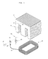
- Figure 1 is an exploded perspective view of principal parts of a high voltage transformer, according to an embodiment of the present invention.
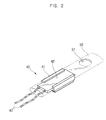
- Figure 2 is a perspective view of a temperature sensor fitted into a shield cover of the preferred high voltage transformer.
- a high voltage transformer includes a secondary coil 20 that is inserted into a laminated E core 10 having a plurality of E iron cores 11 laminated therein, and a temperature sensor 40 that senses the temperature of the secondary coil 20.
- the temperature sensor 40 includes a frame 41 to form an external shape of the sensor 40, an activating plate 42 disposed to face the secondary coil 20, and input lines 43 electrically connected to a primary coil 60 that will be described later.
- An on/off operation of the temperature sensor 40 is carried out in such a way that a movable contact point is attached to or detached from a fixed contact point based on the temperature sensed inside the frame 41.
- the movable and fixed contact points are electrically connected to the input lines 43, respectively, and are disposed under the activating plate 42.
- the activating plate 42 is preferably disposed to face the secondary coil 20 whose temperature is to be sensed.
- a shield cover 50 is made of an insulating material to insulate the temperature sensor 40 fitted therein, and provided to be transparent so that a user may check the temperature sensor 40 with the naked eye.
- the shield cover 50 is extended in a longitudinal direction to enclose the frame 41 of the temperature sensor 40.
- a surface of the frame 41 is stuck to the shield cover 50, and the frame 41 therefore does not easily slide out from the shield cover 50.
- the input lines 43 connected to one side of the frame 41 protrude outside the shield cover 50, and are connected in series to the primary coil 60.
- the temperature sensor 40 is fixedly attached to the laminated E core 10 by a rivet 30 with the temperature sensor 40 fitted into the shield cover 50. That is, the temperature sensor 40 is fixedly attached to the laminated E core 10 by the rivet 30 after a through hole 12 of the laminated E core 10 is aligned with a fastening hole 51 of the shield cover 50.
- a ground line 21 is connected to one side of the secondary coil 20, and a ground element 22 is connected to the ground line 21.
- a fastening hole 23 is formed through the ground element 22. Accordingly, the ground element 22 is fixedly attached to the laminated E core 10 by the rivet 30 after the fastening hole 23 is aligned with the through hole 12 and the fastening hole 51.
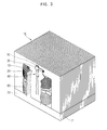
- Figure 3 shows the temperature sensor attached to the laminated E core of the high voltage transformer.
- the laminated E core 10 formed by laminating the plurality of E iron cores 11, and a laminated I core 70 formed by laminating a plurality of I iron cores 71 are joined together. Electric parts which generate a high voltage such as the secondary coil 20 and the primary coil 60, are inserted between the laminated E core 10 and the laminated I core 70.
- Curved front and rear portions of the secondary coil 20 are exposed outside the laminated E core 10, and an installation space 13 is provided between the curved front portion of the secondary coil 20 and the laminated E core 10.
- the temperature sensor 40 fitted into the shield cover 50 is disposed in the installation space 13.
- the temperature sensor 40 is fixedly attached to the laminated E core 10 by the rivet 30 so that the activating plate 42 of the temperature sensor 40 is situated to face the secondary coil 20. Accordingly, a shifting of a position of the temperature sensor 40 is prevented.
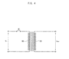
- Figure 4 is a circuit diagram illustrating the temperature sensor connected in series to the primary coil of the high voltage transformer.
- An input voltage V in is applied to the primary coil 60 and an output voltage V out boosted by the secondary coil 20 is output.
- the temperature sensor 40 is connected in series to the primary coil 60, and the activating plate 42 of the temperature sensor 40 is disposed to face the secondary coil 20. If the temperature of the secondary coil 20 is equal to or higher than a preset temperature, the movable contact point is not connected to the fixed contact point, so that the temperature sensor 40 is turned off and the input voltage V in applied to the primary coil 70 is cut off. Accordingly, as an operation of the high voltage transformer is stopped, overheating of the high voltage transformer may be prevented.
- the present invention provides a high voltage transformer, in which a temperature sensor is fixedly attached to a laminated E core by a rivet through a medium of the shield cover of the sensor, thereby preventing the shifting of the position of the temperature sensor.
- the temperature sensor is fixedly attached to the E core so that the activating plate of the temperature sensor is situated to face the secondary coil of the transformer.
- the temperature of the secondary coil may be correctly sensed, and reliability of products using the high voltage transformer may be increased.
Landscapes
- Engineering & Computer Science (AREA)
- Power Engineering (AREA)
- Physics & Mathematics (AREA)
- Electromagnetism (AREA)
- Housings And Mounting Of Transformers (AREA)
- Regulation Of General Use Transformers (AREA)
Abstract
A high voltage transformer includes a fastening to
fixedly attach a temperature sensor (40) to a core (10).
Accordingly, the present invention provides the high
voltage transformer in which the temperature sensor (40)
is fixedly attached to the core (10), thereby preventing a
shifting of a position of the temperature sensor (40).
Description
- The present invention relates, in general, to a high voltage transformer and, more particularly, to a high voltage transformer provided with a temperature sensor to sense a temperature of a coil of the transformer.
- A high voltage transformer is a device that functions to boost an input voltage supplied from an external power supply to a high voltage and output the boosted voltage, and is generally used in electronic products such as a microwave oven.
- The high voltage transformer is manufactured by joining a laminated E core, in which a plurality of E iron cores are laminated, with a laminated I core, in which a plurality of I iron cores are laminated, and disposing electrical parts such as a primary coil and a secondary coil between the laminated E core and the laminated I core.
- Generally, the high voltage transformer is electrically connected between the external power supply and a load, functions to boost voltage supplied from the external power supply, and supplies the boosted voltage to the load. If the high voltage transformer is heated, a temperature of the secondary coil of the transformer connected to the load is excessively increased.
- A high voltage transformer utilized in electronic products operated using a high voltage such as a microwave oven, is provided with a temperature sensor to prevent overheating. The temperature sensor is disposed in a vicinity of the secondary coil of the transformer to control an operation of the transformer based on the temperature of the secondary coil. The temperature sensor is electrically connected in series to the primary coil of the transformer. If the temperature of the secondary coil is equal to or higher than a preset temperature, the operation of the high voltage transformer is stopped by cutting off power supplied to the primary coil.
- The temperature sensor that senses the temperature of the secondary coil of the high voltage transformer is installed by hand. Thus, the temperature sensor is disposed in the vicinity of the secondary coil without being fixed. If the temperature sensor is moved from an initial position, it is difficult to correctly sense the temperature of the secondary coil. Accordingly, there is an inconvenience in that it is determined whether the temperature sensor is disposed in the initial position at a time of manufacturing the high voltage transformer.
- Additionally, although the temperature sensor is disposed in the initial position at the time of manufacturing the high voltage transformer, the temperature sensor may be moved from the initial position due to vibration which may be generated during the operation of the high voltage transformer. Accordingly, a method of stably installing the temperature sensor and correctly sensing the temperature of the secondary coil is needed.
- It is an aim of the present invention to provide a high voltage transformer to prevent a shifting of a position of a temperature sensor, thereby correctly sensing a temperature of a coil of the transformer.
- Other aims and advantages of the invention will be set forth in part in the description which follows and, in part, will be obvious from the description, or may be learned by practice of the invention.
- According to the present invention there is provided an apparatus and method as set forth in the appended claims. Preferred features of the invention will be apparent from the dependent claims, and the description which follows.
- In one aspect of the present invention there is provided a high voltage transformer including a core, a coil disposed in the core, a temperature sensor to sense a temperature of the coil, and a fastening unit to fixedly attach the temperature sensor to the core.
- Preferably, the fastening unit includes a shield cover to allow the temperature sensor to be fitted therein, and a rivet to fasten the shield cover to the core.
- The shield cover includes a fastening hole to allow the rivet to penetrate therethrough.
- The fastening unit fixedly attaches both the shield cover and a ground element that grounds the coil.
- The shield cover is made of an insulating material.
- In another aspect of the present invention there is provided a high voltage transformer including an E core and an I core joined together, and a primary coil and a secondary coil. The secondary coil is disposed in a space provided in the E core. The high voltage transformer also includes a temperature sensor to sense a temperature of the secondary coil, a shield cover to allow the temperature sensor to be fitted therein, and a rivet to fixedly attach the shield cover to the E core.
- The shield cover includes a fastening hole to allow the rivet to penetrate therethrough.
- The rivet fixedly attaches both the shield cover and a ground element that grounds the secondary coil to the E core.
- The shield cover is made of an insulating material.
- For a better understanding of the invention, and to show how embodiments of the same may be carried into effect, reference will now be made, by way of example, to the accompanying diagrammatic drawings in which:
- Figure 1 is an exploded perspective view of principal parts of a high voltage transformer, according to an embodiment of the present invention;
- Figure 2 is a perspective view of a temperature sensor fitted into a shield cover of the present invention;
- Figure 3 shows the temperature sensor of Figure 2 attached to a laminated E core of the high voltage transformer; and
- Figure 4 is a circuit diagram illustrating the temperature sensor connected in series to a primary coil of the high voltage transformer.
-
- Figure 1 is an exploded perspective view of principal parts of a high voltage transformer, according to an embodiment of the present invention. Figure 2 is a perspective view of a temperature sensor fitted into a shield cover of the preferred high voltage transformer.
- As shown in Figures 1 and 2, a high voltage transformer includes a
secondary coil 20 that is inserted into a laminatedE core 10 having a plurality ofE iron cores 11 laminated therein, and atemperature sensor 40 that senses the temperature of thesecondary coil 20. - The
temperature sensor 40 includes aframe 41 to form an external shape of thesensor 40, anactivating plate 42 disposed to face thesecondary coil 20, andinput lines 43 electrically connected to aprimary coil 60 that will be described later. An on/off operation of thetemperature sensor 40 is carried out in such a way that a movable contact point is attached to or detached from a fixed contact point based on the temperature sensed inside theframe 41. The movable and fixed contact points are electrically connected to theinput lines 43, respectively, and are disposed under the activatingplate 42. Additionally, the activatingplate 42 is preferably disposed to face thesecondary coil 20 whose temperature is to be sensed. - A
shield cover 50 is made of an insulating material to insulate thetemperature sensor 40 fitted therein, and provided to be transparent so that a user may check thetemperature sensor 40 with the naked eye. - Additionally, the
shield cover 50 is extended in a longitudinal direction to enclose theframe 41 of thetemperature sensor 40. A surface of theframe 41 is stuck to theshield cover 50, and theframe 41 therefore does not easily slide out from theshield cover 50. Theinput lines 43 connected to one side of theframe 41 protrude outside theshield cover 50, and are connected in series to theprimary coil 60. - The
temperature sensor 40 is fixedly attached to the laminatedE core 10 by arivet 30 with thetemperature sensor 40 fitted into theshield cover 50. That is, thetemperature sensor 40 is fixedly attached to the laminatedE core 10 by therivet 30 after a throughhole 12 of the laminatedE core 10 is aligned with afastening hole 51 of theshield cover 50. - Meanwhile, a ground line 21 is connected to one side of the
secondary coil 20, and aground element 22 is connected to the ground line 21. Afastening hole 23 is formed through theground element 22. Accordingly, theground element 22 is fixedly attached to the laminatedE core 10 by therivet 30 after thefastening hole 23 is aligned with the throughhole 12 and thefastening hole 51. - Figure 3 shows the temperature sensor attached to the laminated E core of the high voltage transformer.
- As shown in Figure 3, in the high voltage transformer, the
laminated E core 10 formed by laminating the plurality ofE iron cores 11, and a laminated Icore 70 formed by laminating a plurality of Iiron cores 71 are joined together. Electric parts which generate a high voltage such as thesecondary coil 20 and theprimary coil 60, are inserted between the laminatedE core 10 and the laminated Icore 70. - Curved front and rear portions of the
secondary coil 20 are exposed outside the laminatedE core 10, and aninstallation space 13 is provided between the curved front portion of thesecondary coil 20 and the laminatedE core 10. Thetemperature sensor 40 fitted into theshield cover 50 is disposed in theinstallation space 13. Here, thetemperature sensor 40 is fixedly attached to the laminatedE core 10 by therivet 30 so that the activatingplate 42 of thetemperature sensor 40 is situated to face thesecondary coil 20. Accordingly, a shifting of a position of thetemperature sensor 40 is prevented. - Figure 4 is a circuit diagram illustrating the temperature sensor connected in series to the primary coil of the high voltage transformer.
- An input voltage Vin is applied to the
primary coil 60 and an output voltage Vout boosted by thesecondary coil 20 is output. - The
temperature sensor 40 is connected in series to theprimary coil 60, and the activatingplate 42 of thetemperature sensor 40 is disposed to face thesecondary coil 20. If the temperature of thesecondary coil 20 is equal to or higher than a preset temperature, the movable contact point is not connected to the fixed contact point, so that thetemperature sensor 40 is turned off and the input voltage Vin applied to theprimary coil 70 is cut off. Accordingly, as an operation of the high voltage transformer is stopped, overheating of the high voltage transformer may be prevented. - As is apparent from the above description, the present invention provides a high voltage transformer, in which a temperature sensor is fixedly attached to a laminated E core by a rivet through a medium of the shield cover of the sensor, thereby preventing the shifting of the position of the temperature sensor.
- Accordingly, it is not necessary to check the position of the temperature sensor at the time of manufacturing the high voltage transformer, and the temperature sensor is fixedly attached to the E core so that the activating plate of the temperature sensor is situated to face the secondary coil of the transformer. Thus, the temperature of the secondary coil may be correctly sensed, and reliability of products using the high voltage transformer may be increased.
- Although a few preferred embodiments have been shown and described, it will be appreciated by those skilled in the art that various changes and modifications might be made without departing from the scope of the invention, as defined in the appended claims.
- Attention is directed to all papers and documents which are filed concurrently with or previous to this specification in connection with this application and which are open to public inspection with this specification, and the contents of all such papers and documents are incorporated herein by reference.
- All of the features disclosed in this specification (including any accompanying claims, abstract and drawings), and/or all of the steps of any method or process so disclosed, may be combined in any combination, except combinations where at least some of such features and/or steps are mutually exclusive.
- Each feature disclosed in this specification (including any accompanying claims, abstract and drawings) may be replaced by alternative features serving the same, equivalent or similar purpose, unless expressly stated otherwise. Thus, unless expressly stated otherwise, each feature disclosed is one example only of a generic series of equivalent or similar features.
- The invention is not restricted to the details of the foregoing embodiment(s). The invention extends to any novel one, or any novel combination, of the features disclosed in this specification (including any accompanying claims, abstract and drawings), or to any novel one, or any novel combination, of the steps of any method or process so disclosed.
Claims (20)
- A high voltage transformer, comprising:a core (10);a coil (20) disposed in the core (10);a temperature sensor (40) to sense a temperature of the coil (20); anda fastening unit (30,50) to fixedly attach the temperature sensor (40) to the core (10).
- The high voltage transformer as set forth in claim 1, wherein the fastening unit (30,50) comprises:a shield cover (50) to allow the temperature sensor (40) to be fitted therein; anda rivet (30) to fasten the shield cover (50) to the core (10).
- The high voltage transformer as set forth in claim 2, wherein the shield cover (50) comprises:a fastening hole (51) to allow the rivet (30) to penetrate therethrough.
- The high voltage transformer as set forth in claim 2 or 3, wherein the fastening unit (30,50) fixedly attaches both the shield cover (50) and a ground element (21) that grounds the coil (20).
- The high voltage transformer as set forth in claim 2, 3 or 4, wherein the shield cover (50) is made of an insulating material.
- A high voltage transformer, comprising:an E core (10) and an I core (70) joined together;a primary coil (60) and a secondary coil (20), the secondary coil (20) being disposed in a space provided in the E core (10);a temperature sensor (40) to sense a temperature of the secondary coil (20);a shield cover (50) to allow the temperature sensor (40) to be fitted therein; anda rivet (40) to fixedly attach the shield cover (50) to the E core (10).
- The high voltage transformer as set forth in claim 6, wherein the shield cover (50) comprises:a fastening hole (51) to allow the rivet (40) to penetrate therethrough.
- The high voltage transformer as set forth in claim 6 or 7, wherein the rivet (40) fixedly attaches the shield cover (50) to the E core (10).
- The high voltage transformer as set forth in claim 6, 7 or 8 wherein the shield cover (50) is made of an insulating material.
- The high voltage transformer as set forth in any of claims 6 to 9, wherein the temperature sensor (40) comprises:a frame (41) to provide an external body of the temperature sensor (40);an activating plate (42) disposed to face the secondary coil (20) and to sense the temperature of the secondary coil (20);a plurality of input lines (48) to electrically connect to the primary coil (60); andmovable and fixed contact points disposed under the activating plate (42) to control an on/off operation of the temperature sensor (40).
- The high voltage transformer as set forth in claim 10, wherein the movable contact point is attached to and detached from the fixed contact point based on a temperature sensed inside the frame (41), and the movable contact point and the fixed contact point are electrically connected to the input lines.
- The high voltage transformer as set forth in any of claims 6 to 11, wherein the shield cover (50) is made of a transparent material to view the temperature sensor (40).
- The high voltage transformer as set forth in any of claims 6 to 12, wherein the shield cover (50) is extended in a direction to enclose the frame (41) of the temperature sensor (40).
- The high voltage transformer as set forth in any of claims 6 to 13, wherein a surface of the frame (41) is stuck to the shield cover (50) to prevent the frame (41) from sliding out from the shield cover (50).
- The high voltage transformer as set forth in any of claims 10 to 14, wherein the input lines are connected to one side of the frame (41) to protrude outside the shield cover (50), and are connected in series to the primary coil (60).
- The high voltage transformer as set forth in any of claims 7 to 15, further comprising:a through hole (12) provided on the E core (10) to align with the fastening hole (51) of the shield cover (50), wherein the rivet (40) fixedly attaches the temperature sensor (40) to the E core (10) by passing through the through hole (12) and the fastening hole (51).
- The high voltage transformer as set forth in any of claims 6 to 16, further comprising:a ground line (21) to connect to one side of the secondary coil (20); anda ground element (22) to connect to the ground line (21), and to ground the secondary coil (20) to the E core (10) via the rivet (40).
- The high voltage transformer as set forth in any of claims 6 to 17, further comprising:an installation space (13) provided between a curved portion of the secondary coil (20) and the E core (10), wherein the temperature sensor (40) is disposed in the installation space (13).
- The high voltage transformer as set forth in any of claims 10 to 18, wherein the temperature sensor (40) is connected in series to the primary coil (60), and is fixedly attached to the E core (10) by the rivet (40) so that the activating plate (42) of the temperature sensor (40) is positioned to face the secondary coil (20), preventing a shifting of the temperature sensor (40).
- The high voltage transformer as set forth in any of claims 11 to 19, wherein when the temperature of the secondary coil (20) is equal to or higher than a preset temperature, the movable contact point is not connected to the fixed contact point, turning the temperature sensor (40) off and preventing overheating of the high voltage transformer.
Applications Claiming Priority (2)
| Application Number | Priority Date | Filing Date | Title |
|---|---|---|---|
| KR1020030005181A KR20040068680A (en) | 2003-01-27 | 2003-01-27 | High voltage transformer |
| KR2003005181 | 2003-01-27 |
Publications (1)
| Publication Number | Publication Date |
|---|---|
| EP1441374A1 true EP1441374A1 (en) | 2004-07-28 |
Family
ID=32589007
Family Applications (1)
| Application Number | Title | Priority Date | Filing Date |
|---|---|---|---|
| EP03253674A Withdrawn EP1441374A1 (en) | 2003-01-27 | 2003-06-11 | High voltage transformer |
Country Status (5)
| Country | Link |
|---|---|
| US (1) | US6812818B2 (en) |
| EP (1) | EP1441374A1 (en) |
| JP (1) | JP2004228558A (en) |
| KR (1) | KR20040068680A (en) |
| CN (1) | CN1269152C (en) |
Cited By (3)
| Publication number | Priority date | Publication date | Assignee | Title |
|---|---|---|---|---|
| EP2568768A3 (en) * | 2011-09-07 | 2013-03-27 | Samsung Electronics Co., Ltd. | Microwave oven |
| FR3028087A1 (en) * | 2014-11-05 | 2016-05-06 | Labinal Power Systems | COIL ELEMENTS HAVING A TEMPERATURE MEASURING DEVICE |
| EP3830847A1 (en) * | 2018-07-31 | 2021-06-09 | Meta System S.p.A. | Wound component |
Families Citing this family (20)
| Publication number | Priority date | Publication date | Assignee | Title |
|---|---|---|---|---|
| GB2405542A (en) * | 2003-08-30 | 2005-03-02 | Sharp Kk | Multiple view directional display having display layer and parallax optic sandwiched between substrates. |
| KR100564014B1 (en) * | 2004-08-09 | 2006-03-24 | 디피씨(주) | Terminal connection structure and method of high-voltage transformer |
| US7319375B2 (en) * | 2004-12-06 | 2008-01-15 | Claude Roy | Universal bench magnet |
| US7889463B1 (en) * | 2005-06-03 | 2011-02-15 | Universal Lighting Technologies, Inc. | Fused lead wire for ballast protection |
| EP2001028B1 (en) * | 2007-06-08 | 2016-11-23 | ABB Technology Oy | Protection of permanent magnets in a DC-inductor |
| US20090066465A1 (en) * | 2007-09-06 | 2009-03-12 | Udo Ausserlechner | Magnetic core for testing magnetic sensors |
| PL2151833T3 (en) * | 2008-08-07 | 2013-08-30 | Starkstrom Geraetebau Gmbh | Transformer system |
| EP2315220B1 (en) * | 2008-08-22 | 2016-03-30 | Sumitomo Electric Industries, Ltd. | Reactor component and reactor |
| JP5515764B2 (en) * | 2010-01-19 | 2014-06-11 | ダイキン工業株式会社 | Temperature detector mounting member |
| BR102012000838A2 (en) * | 2012-01-13 | 2015-03-31 | Evoluç Es En Ltda | Earth's electron pickup |
| CN102623157A (en) * | 2012-04-05 | 2012-08-01 | 南通米兰特电气有限公司 | Novel temperature control ring transformer |
| US10317289B2 (en) * | 2014-09-10 | 2019-06-11 | Rockwell Automation Technologies, Inc. | Thermal well for transformer and methods |
| WO2016069802A1 (en) * | 2014-10-28 | 2016-05-06 | Advanced Charging Technologies, LLC | Electrical circuit for delivering power to consumer electronic devices |
| US10406623B2 (en) * | 2014-11-07 | 2019-09-10 | Illinois Tool Works Inc. | Method and apparatus for providing auxiliary and welding type power with thermal protection |
| JP6380753B2 (en) * | 2014-12-25 | 2018-08-29 | 株式会社オートネットワーク技術研究所 | Reactor |
| JP6628602B2 (en) * | 2015-12-28 | 2020-01-08 | 株式会社タムラ製作所 | Reactor |
| JP6844494B2 (en) * | 2017-02-08 | 2021-03-17 | 株式会社オートネットワーク技術研究所 | Reactor |
| JP6805990B2 (en) * | 2017-07-12 | 2020-12-23 | 株式会社オートネットワーク技術研究所 | Reactor |
| JP6779467B2 (en) * | 2017-08-21 | 2020-11-04 | 株式会社オートネットワーク技術研究所 | Reactor |
| CN116705469B (en) * | 2023-08-07 | 2024-01-16 | 季华实验室 | An LLC transformer assembly structure and its assembly method |
Citations (4)
| Publication number | Priority date | Publication date | Assignee | Title |
|---|---|---|---|---|
| US3827015A (en) * | 1973-04-13 | 1974-07-30 | Minnesota Mining & Mfg | Mounting means for thermal switches |
| JPS5875817A (en) * | 1981-10-29 | 1983-05-07 | Toyo Denso Co Ltd | Method of bringing iron core and coil grounding terminal into contact with each other |
| JPH10189362A (en) * | 1996-12-24 | 1998-07-21 | Matsushita Electric Works Ltd | Mounting structure for temperature protective device |
| US20020089085A1 (en) * | 1999-07-28 | 2002-07-11 | Cheol-Jin Kim | High voltage transformer for microwave oven and method of manufacturing therefor |
Family Cites Families (6)
| Publication number | Priority date | Publication date | Assignee | Title |
|---|---|---|---|---|
| US4179927A (en) * | 1977-09-28 | 1979-12-25 | Electric Power Research Institute, Inc. | Temperature sensing device |
| US4307607A (en) * | 1979-07-16 | 1981-12-29 | Electric Power Research Institute, Inc. | Temperature sensing arrangement and method |
| JPH02161961A (en) * | 1988-12-15 | 1990-06-21 | Nippon Kenko Zoushin Kenkyukai:Kk | Time display device |
| DE59107683D1 (en) * | 1990-11-07 | 1996-05-23 | Ruedi Kaelin | Small transformer and manufacturing process for this |
| DE19616272A1 (en) * | 1996-04-24 | 1997-10-30 | Thomson Brandt Gmbh | Circuit for limiting the beam current of a picture tube |
| DE19842470A1 (en) * | 1998-09-16 | 2000-03-23 | Siemens Ag | Residual current device with overload protection |
-
2003
- 2003-01-27 KR KR1020030005181A patent/KR20040068680A/en not_active Ceased
- 2003-05-20 US US10/441,195 patent/US6812818B2/en not_active Expired - Fee Related
- 2003-06-03 CN CNB031385443A patent/CN1269152C/en not_active Expired - Fee Related
- 2003-06-11 EP EP03253674A patent/EP1441374A1/en not_active Withdrawn
- 2003-11-05 JP JP2003376167A patent/JP2004228558A/en active Pending
Patent Citations (4)
| Publication number | Priority date | Publication date | Assignee | Title |
|---|---|---|---|---|
| US3827015A (en) * | 1973-04-13 | 1974-07-30 | Minnesota Mining & Mfg | Mounting means for thermal switches |
| JPS5875817A (en) * | 1981-10-29 | 1983-05-07 | Toyo Denso Co Ltd | Method of bringing iron core and coil grounding terminal into contact with each other |
| JPH10189362A (en) * | 1996-12-24 | 1998-07-21 | Matsushita Electric Works Ltd | Mounting structure for temperature protective device |
| US20020089085A1 (en) * | 1999-07-28 | 2002-07-11 | Cheol-Jin Kim | High voltage transformer for microwave oven and method of manufacturing therefor |
Non-Patent Citations (2)
| Title |
|---|
| PATENT ABSTRACTS OF JAPAN vol. 007, no. 170 (E - 189) 27 July 1983 (1983-07-27) * |
| PATENT ABSTRACTS OF JAPAN vol. 1998, no. 12 31 October 1998 (1998-10-31) * |
Cited By (7)
| Publication number | Priority date | Publication date | Assignee | Title |
|---|---|---|---|---|
| EP2568768A3 (en) * | 2011-09-07 | 2013-03-27 | Samsung Electronics Co., Ltd. | Microwave oven |
| FR3028087A1 (en) * | 2014-11-05 | 2016-05-06 | Labinal Power Systems | COIL ELEMENTS HAVING A TEMPERATURE MEASURING DEVICE |
| WO2016071614A1 (en) * | 2014-11-05 | 2016-05-12 | Labinal Power Systems | Coiled elements comprising a temperature measuring device |
| CN107077942A (en) * | 2014-11-05 | 2017-08-18 | 赛峰电气与电源公司 | Wound element including temperature measuring equipment |
| US10685779B2 (en) | 2014-11-05 | 2020-06-16 | Safran Electrical & Power | Coiled elements comprising a temperature measuring device |
| EP3830847A1 (en) * | 2018-07-31 | 2021-06-09 | Meta System S.p.A. | Wound component |
| US11984256B2 (en) | 2018-07-31 | 2024-05-14 | Meta System S.P.A. | Wound component |
Also Published As
| Publication number | Publication date |
|---|---|
| US6812818B2 (en) | 2004-11-02 |
| CN1269152C (en) | 2006-08-09 |
| US20040145437A1 (en) | 2004-07-29 |
| KR20040068680A (en) | 2004-08-02 |
| JP2004228558A (en) | 2004-08-12 |
| CN1518016A (en) | 2004-08-04 |
Similar Documents
| Publication | Publication Date | Title |
|---|---|---|
| EP1441374A1 (en) | High voltage transformer | |
| US6316908B2 (en) | Battery charger with wiring opening for conducting wire connection therethrough | |
| US7923971B2 (en) | Non-contact electric power transmission apparatus | |
| CN115136451A (en) | Wireless power transfer system for simultaneous transfer to multiple devices | |
| JP2001044052A (en) | High pressure transformer for microwave oven and method of manufacturing the same | |
| US20260031857A1 (en) | Wireless Power Transmission System Utilizing Multiple Transmission Antennas With Common Electronics | |
| JP6047911B2 (en) | Electronic equipment and power supply system | |
| US7042745B1 (en) | Insulating arrangement for DC/AC inverter | |
| US10243399B2 (en) | Wireless power transmission apparatus installable on wall | |
| GB2373653A (en) | Vehicle slide door power supply system having temperature sensor | |
| US20170359063A1 (en) | Apparatus to secure a sensor assembly for a device touch button | |
| US6998583B2 (en) | Electric cooking apparatus and method of controlling the same | |
| US11876386B2 (en) | Detection of foreign objects in large charging volume applications | |
| KR200156390Y1 (en) | H.v.t apparatus of microwave oven | |
| EP1398998A2 (en) | Magnetron driving circuit board for microwave oven | |
| US7365294B2 (en) | Microwave oven | |
| JP2005063747A (en) | Cooker | |
| JP2892454B2 (en) | microwave | |
| KR100793025B1 (en) | Drive device for electromagnetic shielding heating wire for bedding | |
| US7032405B2 (en) | Apparatus for fixing printed circuit board of refrigerator | |
| JP4049201B2 (en) | Induction heating device | |
| JP2024537035A (en) | Ground pad module having sensor structure - Patents.com | |
| EP3613259B1 (en) | Hand-held induction bonding tool | |
| FR2847115A1 (en) | Inductive device for use in cooking hearth, has magnetic conducting unit arranged on plane in contact with conducting coil where conducting unit has material unit with high heating capacity | |
| JP3972803B2 (en) | Induction heating device |
Legal Events
| Date | Code | Title | Description |
|---|---|---|---|
| PUAI | Public reference made under article 153(3) epc to a published international application that has entered the european phase |
Free format text: ORIGINAL CODE: 0009012 |
|
| 17P | Request for examination filed |
Effective date: 20030701 |
|
| AK | Designated contracting states |
Kind code of ref document: A1 Designated state(s): AT BE BG CH CY CZ DE DK EE ES FI FR GB GR HU IE IT LI LU MC NL PT RO SE SI SK TR |
|
| AX | Request for extension of the european patent |
Extension state: AL LT LV MK |
|
| AKX | Designation fees paid |
Designated state(s): DE FR GB |
|
| 17Q | First examination report despatched |
Effective date: 20081218 |
|
| STAA | Information on the status of an ep patent application or granted ep patent |
Free format text: STATUS: THE APPLICATION IS DEEMED TO BE WITHDRAWN |
|
| 18D | Application deemed to be withdrawn |
Effective date: 20090429 |