EP1441280A2 - Vehicular dialogue interface with centralized commander - Google Patents
Vehicular dialogue interface with centralized commander Download PDFInfo
- Publication number
- EP1441280A2 EP1441280A2 EP20040250208 EP04250208A EP1441280A2 EP 1441280 A2 EP1441280 A2 EP 1441280A2 EP 20040250208 EP20040250208 EP 20040250208 EP 04250208 A EP04250208 A EP 04250208A EP 1441280 A2 EP1441280 A2 EP 1441280A2
- Authority
- EP
- European Patent Office
- Prior art keywords
- switch
- scan
- commander
- vehicular
- centralized
- Prior art date
- Legal status (The legal status is an assumption and is not a legal conclusion. Google has not performed a legal analysis and makes no representation as to the accuracy of the status listed.)
- Ceased
Links
Images


Classifications
-
- G—PHYSICS
- G06—COMPUTING OR CALCULATING; COUNTING
- G06F—ELECTRIC DIGITAL DATA PROCESSING
- G06F3/00—Input arrangements for transferring data to be processed into a form capable of being handled by the computer; Output arrangements for transferring data from processing unit to output unit, e.g. interface arrangements
- G06F3/01—Input arrangements or combined input and output arrangements for interaction between user and computer
- G06F3/048—Interaction techniques based on graphical user interfaces [GUI]
- G06F3/0481—Interaction techniques based on graphical user interfaces [GUI] based on specific properties of the displayed interaction object or a metaphor-based environment, e.g. interaction with desktop elements like windows or icons, or assisted by a cursor's changing behaviour or appearance
- G06F3/0482—Interaction with lists of selectable items, e.g. menus
-
- B—PERFORMING OPERATIONS; TRANSPORTING
- B60—VEHICLES IN GENERAL
- B60K—ARRANGEMENT OR MOUNTING OF PROPULSION UNITS OR OF TRANSMISSIONS IN VEHICLES; ARRANGEMENT OR MOUNTING OF PLURAL DIVERSE PRIME-MOVERS IN VEHICLES; AUXILIARY DRIVES FOR VEHICLES; INSTRUMENTATION OR DASHBOARDS FOR VEHICLES; ARRANGEMENTS IN CONNECTION WITH COOLING, AIR INTAKE, GAS EXHAUST OR FUEL SUPPLY OF PROPULSION UNITS IN VEHICLES
- B60K35/00—Instruments specially adapted for vehicles; Arrangement of instruments in or on vehicles
- B60K35/10—Input arrangements, i.e. from user to vehicle, associated with vehicle functions or specially adapted therefor
-
- G—PHYSICS
- G06—COMPUTING OR CALCULATING; COUNTING
- G06F—ELECTRIC DIGITAL DATA PROCESSING
- G06F3/00—Input arrangements for transferring data to be processed into a form capable of being handled by the computer; Output arrangements for transferring data from processing unit to output unit, e.g. interface arrangements
- G06F3/01—Input arrangements or combined input and output arrangements for interaction between user and computer
- G06F3/03—Arrangements for converting the position or the displacement of a member into a coded form
- G06F3/033—Pointing devices displaced or positioned by the user, e.g. mice, trackballs, pens or joysticks; Accessories therefor
- G06F3/0338—Pointing devices displaced or positioned by the user, e.g. mice, trackballs, pens or joysticks; Accessories therefor with detection of limited linear or angular displacement of an operating part of the device from a neutral position, e.g. isotonic or isometric joysticks
-
- H—ELECTRICITY
- H01—ELECTRIC ELEMENTS
- H01H—ELECTRIC SWITCHES; RELAYS; SELECTORS; EMERGENCY PROTECTIVE DEVICES
- H01H25/00—Switches with compound movement of handle or other operating part
- H01H25/04—Operating part movable angularly in more than one plane, e.g. joystick
- H01H25/041—Operating part movable angularly in more than one plane, e.g. joystick having a generally flat operating member depressible at different locations to operate different controls
-
- B—PERFORMING OPERATIONS; TRANSPORTING
- B60—VEHICLES IN GENERAL
- B60K—ARRANGEMENT OR MOUNTING OF PROPULSION UNITS OR OF TRANSMISSIONS IN VEHICLES; ARRANGEMENT OR MOUNTING OF PLURAL DIVERSE PRIME-MOVERS IN VEHICLES; AUXILIARY DRIVES FOR VEHICLES; INSTRUMENTATION OR DASHBOARDS FOR VEHICLES; ARRANGEMENTS IN CONNECTION WITH COOLING, AIR INTAKE, GAS EXHAUST OR FUEL SUPPLY OF PROPULSION UNITS IN VEHICLES
- B60K2360/00—Indexing scheme associated with groups B60K35/00 or B60K37/00 relating to details of instruments or dashboards
- B60K2360/11—Instrument graphical user interfaces or menu aspects
-
- B—PERFORMING OPERATIONS; TRANSPORTING
- B60—VEHICLES IN GENERAL
- B60K—ARRANGEMENT OR MOUNTING OF PROPULSION UNITS OR OF TRANSMISSIONS IN VEHICLES; ARRANGEMENT OR MOUNTING OF PLURAL DIVERSE PRIME-MOVERS IN VEHICLES; AUXILIARY DRIVES FOR VEHICLES; INSTRUMENTATION OR DASHBOARDS FOR VEHICLES; ARRANGEMENTS IN CONNECTION WITH COOLING, AIR INTAKE, GAS EXHAUST OR FUEL SUPPLY OF PROPULSION UNITS IN VEHICLES
- B60K2360/00—Indexing scheme associated with groups B60K35/00 or B60K37/00 relating to details of instruments or dashboards
- B60K2360/139—Clusters of instrument input devices
-
- H—ELECTRICITY
- H01—ELECTRIC ELEMENTS
- H01H—ELECTRIC SWITCHES; RELAYS; SELECTORS; EMERGENCY PROTECTIVE DEVICES
- H01H25/00—Switches with compound movement of handle or other operating part
- H01H25/04—Operating part movable angularly in more than one plane, e.g. joystick
- H01H25/041—Operating part movable angularly in more than one plane, e.g. joystick having a generally flat operating member depressible at different locations to operate different controls
- H01H2025/045—Operating part movable angularly in more than one plane, e.g. joystick having a generally flat operating member depressible at different locations to operate different controls having a rotating dial around the operating member for additional switching functions
-
- H—ELECTRICITY
- H01—ELECTRIC ELEMENTS
- H01H—ELECTRIC SWITCHES; RELAYS; SELECTORS; EMERGENCY PROTECTIVE DEVICES
- H01H25/00—Switches with compound movement of handle or other operating part
- H01H25/04—Operating part movable angularly in more than one plane, e.g. joystick
- H01H2025/048—Operating part movable angularly in more than one plane, e.g. joystick having a separate central push, slide or tumbler button which is not integral with the operating part that surrounds it
Definitions
- the present invention relates to a vehicular interface between a vehicle driver or passenger and vehicle equipment, and in particular, to a vehicular interface allowing a dialogue therebetween.
- Recent vehicles have various electric or electronic auxiliary equipment including, for example, a navigation system, an air conditioner, an audio or video system, and electrical appliances. They are provided with controls and elements for their operations, which are collected to a single operational module or equipment that serves as an interface between a vehicle driver or passenger and vehicle-mounted equipment.
- Ref-1 Japanese Patent Application Laying-Open Publication No. 2001-294101
- Ref-1 has disclosed a vehicular interface of a dialogue concept including a display for visualized presentation of an operation menu, and a “centralized (i.e. single-localized and operation-commonized) combination of manually operable switching elements or controls” (hereafter called “centralized commander”) as a common member having a central switch region for decision, and a peripheral switch region for directional inching scans in the operation menu.
- centralized commander i.e. single-localized and operation-commonized combination of manually operable switching elements or controls
- the centralized commander may undergo an erroneous touch on the central region during a traverse scan to be effected by repetition of inching scan(s) using the peripheral region.
- the present invention has been made with this point in view. It is an object of the invention to provide a vehicular dialogue interface with a centralized commander having a reduced tendency to suffer from erroneous touch.
- the invention provides a vehicular dialogue interface comprising a display and a centralized commander comprising a first switch operable for scanning for one item to an adjacent item on the display in a first direction, hereinafter called an inching scan, and a second switch operable for scanning from a first set of items to a second set of items on the display in a second direction different from the first direction, hereinafter called a traverse scan.
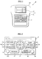
- Fig. 1 shows a vehicular dialogue interface panel IP provided with a display panel DP and a cluster lid C according to an embodiment of the invention; and Fig. 2, an interface module 2 on the cluster lid C.
- the dialogue interface panel IP is configured as an interface between a vehicle driver or passenger and a vehicle-mounted computer, and includes the display panel DP and the cluster lid C, as peripheral components of the computer.
- the interface panel IP serves as part of a vehicular input apparatus 1 adapted for manual input operations, that is constituted by a vehicular operating apparatus configured as the interface module 2 on the cluster lid C, and a dialogue display element configured as an LCD 3 on the display panel DP.
- the LCD 3 is adapted to display various programmed or manually selected operational information, e.g. title and sub-item menu of an operational item selected by the interface module 2. Any desired item in the sub-item menu on the LCD 3 cal also be selected by the module 2.
- the interface module 2 is adapted for a centralized or collected operation of vehicular auxiliary equipment, and has a centralized commander 5 installed at the center of module 2.
- the commander 5 is configured to be actuated by a sequence of rotational, eight-directional, and/or pressing single-hand operations by a vehicle driver or passenger to provide a manual command for a traverse and/or inching scan of key or menu items, and/or decision with respect to key operation or menu item selection, as necessary for operation of concerned equipment
- the module 2 further has a set of LED-illuminated or touch-panel-superposed operational keys K wholly arranged around the commander 5, and each respectively adapted as a control or switching element to be operated or selected by a direct (e.g. finger touch or press) command thereto or indirect command via the commander 5. More specifically, the module 2 has: (as the keys K) at the left of commander 5, a left key group 4a including a navigation menu key 41, a map and guide key 42, and a destination key 43; at the right of commander 5, a right key group 4b including an audio key 44, an air conditioner key 45, and an information key 46; and under the commander 5, a program key 47 provided with an indicator 47a, and a traffic information key 48. Also a volume control 49 is provided on the module 2.
- Any key 41-46 in the left and right key groups 4a, 4b can be operated or selected by a corresponding command from the commander 5.
- the destination key 43 is selected and highlighted, by pressing this key 43 directly, or by pushing a left lower diagonal part of the commander 5.
- Fig. 3A is a perspective view of the centralized commander 5, and Fig. 3B, a section along line IIIB- IIIB of Fig. 3A.
- the centralized commander 5 is configured with: a central, circular, independent knob or push-button type switch for decision use (hereafter called “decision switch”) 6; an annular, LED-illuminated eight-directional, inching-scan-oriented, continuously operable, independent flat-knob or disc-tilting switch (hereafter called “first scan switch”) 7 surrounding the decision switch 6; a peripheral or circumferential, rotation angle encoding, traverse-scan-oriented, inching scan applicable, independent dial switch (hereafter called “second scan switch”) 9 surrounding the first scan switch 7, together with a rotary encoder member 8 therefor, and a common base structure 14 supporting the encoder member 8, and a circuit-printed/incorporated common substrate 13 of the decision switch 6 and first scan switch 7.
- first scan switch annular, LED-illuminated eight-directional, inching-scan-oriented, continuously operable, independent flat-knob or disc-tilting switch
- second scan switch a peripheral or circumferential, rotation angle encoding, traverse-scan-oriented
- the decision switch 6 is configured to be pressed down to make its diameter-reduced lower end 6a push a contact 10a of a tact switch 10 on the substrate 13.
- the first scan switch 7 is configured to be pressed down at an arbitrary one of eight sector regions about triangular or circular indicators 11 or 12 thereon, to make a corresponding downward projection 7a thereof push a contact (e.g. 11b) of a mating one (e.g. 11a) of eight tact switches on the substrate 13, while the number of tact switches may be four. With a pushed contact, the tact switch turns on, illuminating or lighting the indicator 11 or 12 of a corresponding sector region by an associated LED (e.g. 12a).
- the second scan switch 9 is configured to be rotated at a desired angle, so that this angle is detected or encoded via the encoder member 8, to effect a corresponding traverse scan.
- Fig. 4 shows a vertical traverse scan (bold arrows) effected in a frame of destination menu on the LCD 3, by a corresponding CW (clockwise) and/or CCW (counterclockwise) rotation Y1 of the second scan switch 9 at the centralized commander 5.
- a second menu item "FROM ALPHABETS" Z2 is selected and highlighted after a downward inching scan (from 1 st item Z1) or an upward inching scan (from 3 rd item Z3) or traverse scan (from 4 th or 5 th item Z4 or Z5).
- the destination menu has an indication part 22 as a GUI (graphical user interface) element defined by lefts ends of menu items Z1 to Z5, so that the indication part 22 is arcuate in conformity with an arcuate right side of the second scan switch 9, allowing a facilitated high-speed scan.
- the GUI element may be defined as a configuration, direction or sense, or other geographical feature that interconnects the scan and switch.
- Fig. 5B shows eight directional inching commands S1 to S8 each respectively selective by a directional operation to a corresponding sector region on the first scan switch 7 of commander 5.
- a selected column 21, fourth column ⁇ X 41 , X 42 , X 43 , X 44 , X 45 ⁇ in this case, is highlighted after a horizontal traverse scan (bold arrows) by a corresponding rotation Y2 of the second scan switch 7, to be fixed by pressing the decision switch 6.
- a corresponding element X 45 of a fifth row ⁇ X 15 ,..., X b5 ⁇ is selected by repetition of or one-time application of a downward inching scan following a corresponding inching command S5, to be fixed and indicated (as X 45 ) at a header of the matrix frame by pressing the decision switch 6.
- Figs. 6A, 6B and 7A, 7B sequentially illustrate a correction procedure of an erroneous selection on the code matrix displayed on the LCD 3.
- a third-row element X 13 is selected and fixed as an erroneous last letter of a word ⁇ X 45 , X 13 , X 22 , X b5 , X 85 , X 24 ⁇ to be searched from 100 records of destination.
- a selected second column ⁇ X 21 , X 22 , X 23 , X 24 , X 25 ⁇ 21 has a third-row element X 23 thereof selected and highlighted, to be indicated at the header of code frame.
- a downward inching scan (bold arrow) is effected by pushing down a corresponding sector region on the first scan switch of commander 5, to select a fourth-row element X 24 of the second column, which element is highlighted and indicated at the header of code frame, to be fixed as a correct last letter of the word to be searched.
- first and second scan switches 7, 9 are operable for scans in different or crossing directions, e.g. column and row directions, with a reduced frequency of erroneous operations, allowing an ensured facile and fast selection.
- the decision switch 6 and scan switches 7, 9 are independently operable relative to each other. Unintentional operation of switch 6 is thus possibly avoided irrespective of pressing position or angle of switch 7. Traverse or diagonal inching scan by switch 7 and/or 9 allows an efficient selection with less actions or eye movements of driver or passenger, leading to an improved operation and less disturbance.
- Switches 7 or 9 may be exclusive for scans in column or row direction, respectively, or vice versa.
Landscapes
- Engineering & Computer Science (AREA)
- General Engineering & Computer Science (AREA)
- Theoretical Computer Science (AREA)
- Human Computer Interaction (AREA)
- Physics & Mathematics (AREA)
- General Physics & Mathematics (AREA)
- Transportation (AREA)
- Combustion & Propulsion (AREA)
- Chemical & Material Sciences (AREA)
- Mechanical Engineering (AREA)
- Switches With Compound Operations (AREA)
- Input From Keyboards Or The Like (AREA)
- Instrument Panels (AREA)
- Mechanical Control Devices (AREA)
- Position Input By Displaying (AREA)
- Switch Cases, Indication, And Locking (AREA)
- Navigation (AREA)
- Selective Calling Equipment (AREA)
Abstract
Description
- The present invention relates to a vehicular interface between a vehicle driver or passenger and vehicle equipment, and in particular, to a vehicular interface allowing a dialogue therebetween.
- Recent vehicles have various electric or electronic auxiliary equipment including, for example, a navigation system, an air conditioner, an audio or video system, and electrical appliances. They are provided with controls and elements for their operations, which are collected to a single operational module or equipment that serves as an interface between a vehicle driver or passenger and vehicle-mounted equipment.
- Japanese Patent Application Laying-Open Publication No. 2001-294101 (hereafter referred to "Ref-1") has disclosed a vehicular interface of a dialogue concept including a display for visualized presentation of an operation menu, and a "centralized (i.e. single-localized and operation-commonized) combination of manually operable switching elements or controls" (hereafter called "centralized commander") as a common member having a central switch region for decision, and a peripheral switch region for directional inching scans in the operation menu.
- In the Ref-1, the centralized commander may undergo an erroneous touch on the central region during a traverse scan to be effected by repetition of inching scan(s) using the peripheral region.
- The present invention has been made with this point in view. It is an object of the invention to provide a vehicular dialogue interface with a centralized commander having a reduced tendency to suffer from erroneous touch.
- To achieve the object, according to an aspect of the invention, the invention provides a vehicular dialogue interface comprising a display and a centralized commander comprising a first switch operable for scanning for one item to an adjacent item on the display in a first direction, hereinafter called an inching scan, and a second switch operable for scanning from a first set of items to a second set of items on the display in a second direction different from the first direction, hereinafter called a traverse scan.
- The above and further objects and novel features of the present invention will more fully appear from the following detailed description when the same is read in conjunction with the accompanying drawings, in which:
- Fig. 1 is a front view of a vehicular dialogue interface panel provided with a display panel and a cluster lid according to an embodiment of the invention;
- Fig. 2 is a front view of an interface module on the cluster lid;
- Fig. 3A is a perspective view of a centralized commander of the interface module;
- Fig. 3B is a section along line IIIB-IIIB of Fig. 3A;
- Fig. 4 is an illustration of an LCD (liquid crystal display) on the display panel and the commander operated for a command to make a traverse scan in a menu on the LCD;
- Fig. 5A is an illustration of the LCD with a code matrix adapted for traverse and inching scans to determine an intersect of column and row defining a letter of a destination to be searched;
- Fig. 5B is an illustration of eight directional inching commands selective by the commander;
- Fig. 6A is an illustration of the LCD with the code matrix erroneously scanned in the determination of destination;
- Fig. 6B is an illustration of the LCD with the code matrix under a traverse scan for column correction;
- Fig. 7A is an illustration of the LCD with the code matrix scanned for selection of a correct column; and
- Fig. 7B is an illustration of the LCD with the code matrix under an inching scan for row correction.
-
- There will be detailed below an embodiment of the present invention with reference to the accompanying drawings.
- Fig. 1 shows a vehicular dialogue interface panel IP provided with a display panel DP and a cluster lid C according to an embodiment of the invention; and Fig. 2, an
interface module 2 on the cluster lid C. - The dialogue interface panel IP is configured as an interface between a vehicle driver or passenger and a vehicle-mounted computer, and includes the display panel DP and the cluster lid C, as peripheral components of the computer. In terms of vehicular operation system, the interface panel IP serves as part of a vehicular input apparatus 1 adapted for manual input operations, that is constituted by a vehicular operating apparatus configured as the
interface module 2 on the cluster lid C, and a dialogue display element configured as anLCD 3 on the display panel DP. - The
LCD 3 is adapted to display various programmed or manually selected operational information, e.g. title and sub-item menu of an operational item selected by theinterface module 2. Any desired item in the sub-item menu on theLCD 3 cal also be selected by themodule 2. - The
interface module 2 is adapted for a centralized or collected operation of vehicular auxiliary equipment, and has a centralizedcommander 5 installed at the center ofmodule 2. Thecommander 5 is configured to be actuated by a sequence of rotational, eight-directional, and/or pressing single-hand operations by a vehicle driver or passenger to provide a manual command for a traverse and/or inching scan of key or menu items, and/or decision with respect to key operation or menu item selection, as necessary for operation of concerned equipment - The
module 2 further has a set of LED-illuminated or touch-panel-superposed operational keys K wholly arranged around thecommander 5, and each respectively adapted as a control or switching element to be operated or selected by a direct (e.g. finger touch or press) command thereto or indirect command via thecommander 5. More specifically, themodule 2 has: (as the keys K) at the left ofcommander 5, a left key group 4a including anavigation menu key 41, a map and guide key 42, and adestination key 43; at the right ofcommander 5, aright key group 4b including anaudio key 44, anair conditioner key 45, and aninformation key 46; and under thecommander 5, aprogram key 47 provided with anindicator 47a, and atraffic information key 48. Also avolume control 49 is provided on themodule 2. Any key 41-46 in the left andright key groups 4a, 4b can be operated or selected by a corresponding command from thecommander 5. For example, in Fig. 2, thedestination key 43 is selected and highlighted, by pressing thiskey 43 directly, or by pushing a left lower diagonal part of thecommander 5. - Fig. 3A is a perspective view of the centralized
commander 5, and Fig. 3B, a section along line IIIB- IIIB of Fig. 3A. - The
centralized commander 5 is configured with: a central, circular, independent knob or push-button type switch for decision use (hereafter called "decision switch") 6; an annular, LED-illuminated eight-directional, inching-scan-oriented, continuously operable, independent flat-knob or disc-tilting switch (hereafter called "first scan switch") 7 surrounding thedecision switch 6; a peripheral or circumferential, rotation angle encoding, traverse-scan-oriented, inching scan applicable, independent dial switch (hereafter called "second scan switch") 9 surrounding thefirst scan switch 7, together with arotary encoder member 8 therefor, and acommon base structure 14 supporting theencoder member 8, and a circuit-printed/incorporatedcommon substrate 13 of thedecision switch 6 andfirst scan switch 7. - The
decision switch 6 is configured to be pressed down to make its diameter-reducedlower end 6a push acontact 10a of atact switch 10 on thesubstrate 13. Thefirst scan switch 7 is configured to be pressed down at an arbitrary one of eight sector regions about triangular orcircular indicators downward projection 7a thereof push a contact (e.g. 11b) of a mating one (e.g. 11a) of eight tact switches on thesubstrate 13, while the number of tact switches may be four. With a pushed contact, the tact switch turns on, illuminating or lighting theindicator second scan switch 9 is configured to be rotated at a desired angle, so that this angle is detected or encoded via theencoder member 8, to effect a corresponding traverse scan. - Fig. 4 shows a vertical traverse scan (bold arrows) effected in a frame of destination menu on the
LCD 3, by a corresponding CW (clockwise) and/or CCW (counterclockwise) rotation Y1 of thesecond scan switch 9 at the centralizedcommander 5. - In Fig. 4, a second menu item "FROM ALPHABETS" Z2 is selected and highlighted after a downward inching scan (from 1st item Z1) or an upward inching scan (from 3rd item Z3) or traverse scan (from 4th or 5th item Z4 or Z5). It is noted that the destination menu has an
indication part 22 as a GUI (graphical user interface) element defined by lefts ends of menu items Z1 to Z5, so that theindication part 22 is arcuate in conformity with an arcuate right side of thesecond scan switch 9, allowing a facilitated high-speed scan. The GUI element may be defined as a configuration, direction or sense, or other geographical feature that interconnects the scan and switch. - Fig. 5A shows a frame of code matrix displayed on the
LCD 3, as a 5-row 11-column matrix {Xnm: n = 1, 2, 3, 4, 5, 6, 7, 8, 9, a, b; m = 1, 2, 3, 4, 5} of letters including alphabets, marks, and legends to be controlled under the second menu item Z2 of destination menu. Fig. 5B shows eight directional inching commands S1 to S8 each respectively selective by a directional operation to a corresponding sector region on thefirst scan switch 7 ofcommander 5. - In Fig. 5A, a selected
column 21, fourth column {X41, X42, X43, X44, X45} in this case, is highlighted after a horizontal traverse scan (bold arrows) by a corresponding rotation Y2 of thesecond scan switch 7, to be fixed by pressing thedecision switch 6. Then, a corresponding element X45 of a fifth row {X15,..., Xb5} is selected by repetition of or one-time application of a downward inching scan following a corresponding inching command S5, to be fixed and indicated (as X45) at a header of the matrix frame by pressing thedecision switch 6. - Figs. 6A, 6B and 7A, 7B sequentially illustrate a correction procedure of an erroneous selection on the code matrix displayed on the
LCD 3. - In Fig. 6A, in a selected first column {X11, X12, X13, X14, X15} 21, a third-row element X13is selected and fixed as an erroneous last letter of a word {X45, X13, X22, Xb5, X85, X24} to be searched from 100 records of destination.
- In Fig. 6B, after a leftward inching scan (bold arrow) by a corresponding rotation Y3 of the second scan switch of
commander 5, a selected second column {X21, X22, X23, X24, X25} 21 has a third-row element X23 thereof selected and highlighted, to be indicated at the header of code frame. - In Fig. 7B, the selected element X23 is once fixed by pressing the
decision switch 6. - Then, as in Fig. 7B, a downward inching scan (bold arrow) is effected by pushing down a corresponding sector region on the first scan switch of
commander 5, to select a fourth-row element X24 of the second column, which element is highlighted and indicated at the header of code frame, to be fixed as a correct last letter of the word to be searched. - It is noted that the first and second scan switches 7, 9 are operable for scans in different or crossing directions, e.g. column and row directions, with a reduced frequency of erroneous operations, allowing an ensured facile and fast selection. The
decision switch 6 andscan switches switch 6 is thus possibly avoided irrespective of pressing position or angle ofswitch 7. Traverse or diagonal inching scan byswitch 7 and/or 9 allows an efficient selection with less actions or eye movements of driver or passenger, leading to an improved operation and less disturbance.Switches - While an embodiment of the invention has been described using specific terms, such description is for illustrative purposes, and it is to be understood that changes and variations may be made without departing from the scope of the following claims.
Claims (5)
- A vehicle dialogue interface (IP) comprising:a display (3) for displaying a plurality of items; anda centralized commander (5), characterised in that the centralized commander (5) comprisesa first switch (7) operable for scanning from one item to an adjacent item on the display (3) in a first direction, anda second switch (9) operable for scanning from a first set of items to a second set of items on the display (3) in a second direction different from the first direction.
- A vehicular dialogue interface (IP) according to claim 1, wherein the centralized commander (5) further comprises a decision switch (6).
- A vehicle dialogue interface (IP) according to claim 1 or 2, wherein the first direction is perpendicular to the second direction.
- A vehicle dialogue interface (IP) according any one of preceding claims, wherein the first switch (7) is eight-directional.
- A vehicular dialogue interface (IP) according to any one of preceding claims, wherein the display (3) has a GUI element (22) relative to a configuration of the second switch (9).
Applications Claiming Priority (2)
| Application Number | Priority Date | Filing Date | Title |
|---|---|---|---|
| JP2003009953 | 2003-01-17 | ||
| JP2003009953A JP3988646B2 (en) | 2003-01-17 | 2003-01-17 | Vehicle control device |
Publications (2)
| Publication Number | Publication Date |
|---|---|
| EP1441280A2 true EP1441280A2 (en) | 2004-07-28 |
| EP1441280A3 EP1441280A3 (en) | 2006-08-30 |
Family
ID=32588566
Family Applications (1)
| Application Number | Title | Priority Date | Filing Date |
|---|---|---|---|
| EP20040250208 Ceased EP1441280A3 (en) | 2003-01-17 | 2004-01-16 | Vehicular dialogue interface with centralized commander |
Country Status (4)
| Country | Link |
|---|---|
| US (1) | US7248252B2 (en) |
| EP (1) | EP1441280A3 (en) |
| JP (1) | JP3988646B2 (en) |
| CN (1) | CN1305700C (en) |
Cited By (4)
| Publication number | Priority date | Publication date | Assignee | Title |
|---|---|---|---|---|
| DE102005017781A1 (en) * | 2005-04-17 | 2006-10-19 | Willtek Communications Gmbh | Operating device with rotary knob and button |
| FR2895502A1 (en) * | 2005-12-28 | 2007-06-29 | E Lead Electronic Co Ltd | NAVIGATION DEVICE USED IN ONE HAND |
| DE102006011276B3 (en) * | 2006-03-10 | 2007-09-06 | Silcos Gmbh | Multiple switch for actuation of different control systems in motor vehicle, has turntable and push button stored in axis of rotation of turntable for confirmation of target samples, and two push-buttons are provided |
| EP1760573A3 (en) * | 2005-08-30 | 2009-06-10 | Samsung Electronics Co., Ltd. | Apparatus and method for controlling user interface using jog dial and navigation key |
Families Citing this family (44)
| Publication number | Priority date | Publication date | Assignee | Title |
|---|---|---|---|---|
| JP4121730B2 (en) * | 2001-01-19 | 2008-07-23 | 富士通コンポーネント株式会社 | Pointing device and portable information device |
| US8127229B2 (en) * | 2004-08-31 | 2012-02-28 | Access Co., Ltd. | Controlling focus, and movement of the focus, between focus items in a multi-frame document |
| EP1677180A1 (en) * | 2004-12-30 | 2006-07-05 | Volkswagen Aktiengesellschaft | Touchscreen capable of detecting two simultaneous touch locations |
| DE102005038161A1 (en) * | 2004-12-30 | 2006-07-13 | Volkswagen Ag | Input device for cockpit of land vehicle, controls e.g. brushless DC actuator as function of speed of touching movement over operating surface or quantity derived from speed |
| WO2006074712A2 (en) * | 2004-12-30 | 2006-07-20 | Volkswagen Aktiengesellschaft | Input device and method for the operation thereof |
| JP2007036508A (en) * | 2005-07-26 | 2007-02-08 | Hitachi Ltd | Input device and remote control device |
| JP4699916B2 (en) * | 2006-02-23 | 2011-06-15 | アルプス電気株式会社 | Multi-directional input device |
| US7732756B2 (en) * | 2006-11-01 | 2010-06-08 | Avago Technologies Ecbu Ip (Singapore) Pte. Ltd. | User navigation device with a code wheel and an encoder |
| JP4951425B2 (en) * | 2007-07-10 | 2012-06-13 | ペンタックスリコーイメージング株式会社 | Operation button |
| JP4965656B2 (en) * | 2007-08-07 | 2012-07-04 | 株式会社オートネットワーク技術研究所 | Operating device |
| DE102007039444A1 (en) * | 2007-08-21 | 2009-02-26 | Volkswagen Ag | Method for displaying information in a motor vehicle and display device for a motor vehicle |
| USD579456S1 (en) * | 2007-09-28 | 2008-10-28 | Industrial Technology Research Institute | Graphic user interface for a display panel |
| US20090132496A1 (en) * | 2007-11-16 | 2009-05-21 | Chen-Kun Chen | System And Method For Technique Document Analysis, And Patent Analysis System |
| US8373880B2 (en) * | 2008-03-26 | 2013-02-12 | Industrial Technology Research Institute | Technical documents capturing and patents analysis system and method |
| USD624028S1 (en) | 2008-09-03 | 2010-09-21 | Caterpillar Inc | Manual control device |
| US20100050803A1 (en) * | 2008-09-03 | 2010-03-04 | Caterpillar Inc. | Manual control device |
| USD598923S1 (en) | 2008-10-09 | 2009-08-25 | Industrial Technology Research Institute | Graphic user interface for a display panel |
| JP2011111061A (en) * | 2009-11-27 | 2011-06-09 | Fujitsu Ten Ltd | On-vehicle display system |
| JP5427008B2 (en) * | 2009-11-27 | 2014-02-26 | 富士通テン株式会社 | In-vehicle display system |
| CN102741662B (en) * | 2010-01-13 | 2016-09-14 | Qsc公司 | Light-operated Electronic control equipment |
| CN103810013B (en) * | 2012-11-13 | 2016-12-21 | 中科英华湖州工程技术研究中心有限公司 | Programming Auxiliary Processing Unit based on toggle switch array and method |
| JP5954156B2 (en) * | 2012-12-14 | 2016-07-20 | マツダ株式会社 | In-vehicle information processing equipment |
| AU350141S (en) * | 2013-01-04 | 2013-08-13 | Samsung Electronics Co Ltd | Display Screen For An Electronic Device |
| AU350322S (en) * | 2013-01-04 | 2013-08-23 | Samsung Electronics Co Ltd | Display Screen For An Electronic Device |
| AU350314S (en) * | 2013-01-05 | 2013-08-23 | Samsung Electronics Co Ltd | Display Screen For An Electronic Device |
| JP5962521B2 (en) | 2013-01-15 | 2016-08-03 | 株式会社デンソー | Vehicle operation system and information equipment |
| CN103198989B (en) * | 2013-04-07 | 2014-03-12 | 苏州华昌机电有限公司 | Modularization combination switch |
| KR101601393B1 (en) | 2014-02-20 | 2016-03-09 | 현대자동차주식회사 | Emergency button for vehicle |
| GB201411309D0 (en) | 2014-06-25 | 2014-08-06 | Tomtom Int Bv | Vehicular human machine interfaces |
| DE102014216389A1 (en) * | 2014-08-19 | 2016-02-25 | BSH Hausgeräte GmbH | Operating device for a household appliance with stably positioned annular control element front part and household appliance with such an operating device |
| KR101566757B1 (en) | 2014-10-10 | 2015-11-06 | 현대자동차 주식회사 | Variable integrated controller |
| USD783039S1 (en) * | 2014-12-31 | 2017-04-04 | Samsung Electronics Co., Ltd. | Display screen or portion thereof with graphical user interface |
| JP6552842B2 (en) * | 2015-03-04 | 2019-07-31 | 古野電気株式会社 | Mark display device for ship navigation |
| KR101696592B1 (en) * | 2015-07-21 | 2017-01-16 | 현대자동차주식회사 | Vehicle and controlling method of the same |
| USD811419S1 (en) | 2015-09-18 | 2018-02-27 | Sap Se | Display screen or portion thereof with graphical user interface |
| USD783651S1 (en) * | 2015-09-18 | 2017-04-11 | Sap Se | Display screen or portion thereof with graphical user interface |
| USD825603S1 (en) * | 2015-09-18 | 2018-08-14 | Sap Se | Display screen or portion thereof with graphical user interface |
| JP6557201B2 (en) * | 2016-09-28 | 2019-08-07 | 矢崎総業株式会社 | In-vehicle device operation device |
| KR102524294B1 (en) * | 2018-11-20 | 2023-04-21 | 현대자동차주식회사 | Method and apparatus for controlling vehicle using dial knob |
| USD1067922S1 (en) * | 2020-09-11 | 2025-03-25 | Aristocrat Technologies, Inc. (ATI) | Display screen or portion thereof with graphical user interface |
| USD1012109S1 (en) | 2022-04-25 | 2024-01-23 | Sap Se | Display screen or portion thereof with graphical user interface |
| US12613546B2 (en) | 2024-07-30 | 2026-04-28 | Dell Products L.P. | Mobile passive joystick with magnet sensing |
| US12596443B2 (en) | 2024-07-30 | 2026-04-07 | Dell Products L.P. | System and method for obtaining user input with magnetic sensing using a track ball |
| US12591321B2 (en) * | 2024-07-30 | 2026-03-31 | Dell Products L.P. | Dial based human interface device |
Family Cites Families (32)
| Publication number | Priority date | Publication date | Assignee | Title |
|---|---|---|---|---|
| US588346A (en) * | 1897-08-17 | Arthur mikeault | ||
| DE3836555A1 (en) | 1988-10-27 | 1990-05-10 | Bayerische Motoren Werke Ag | MULTIFUNCTION CONTROL DEVICE |
| JPH0741928A (en) | 1993-07-28 | 1995-02-10 | Sumitomo Metal Ind Ltd | Discoloration prevention method for internal annealing furnace members |
| JP3325685B2 (en) | 1993-12-28 | 2002-09-17 | 松下電器産業株式会社 | Input device |
| DE19608869C2 (en) | 1996-03-07 | 1998-03-26 | Daimler Benz Ag | Operating system, in particular for components in a motor vehicle |
| DE19610344A1 (en) | 1996-03-18 | 1997-09-25 | Philips Patentverwaltung | Multifunction control device for a vehicle, e.g. B. for a motor vehicle |
| DE19646226A1 (en) * | 1996-03-19 | 1998-05-14 | Bayerische Motoren Werke Ag | Operating device for menu-controlled functions of a vehicle |
| DE19639119A1 (en) | 1996-09-24 | 1998-03-26 | Philips Patentverwaltung | Electronic device with a bidirectional rotary switch |
| JP3221839B2 (en) | 1996-10-04 | 2001-10-22 | 株式会社デンソー | Switch device for operating onboard equipment |
| JPH10144182A (en) | 1996-11-14 | 1998-05-29 | Kojima Press Co Ltd | Integral type multifunction operation switch device |
| US6636197B1 (en) * | 1996-11-26 | 2003-10-21 | Immersion Corporation | Haptic feedback effects for control, knobs and other interface devices |
| JPH10340152A (en) | 1997-06-05 | 1998-12-22 | Matsushita Electric Ind Co Ltd | On-vehicle audio system and its operating method |
| JPH11151996A (en) | 1997-11-20 | 1999-06-08 | Matsushita Electric Ind Co Ltd | Automotive audio equipment |
| DE19843421B4 (en) | 1997-11-25 | 2007-07-05 | Bayerische Motoren Werke Ag | Device for selecting points of a menu structure consisting of menus and / or submenus and / or functions and / or function values |
| DE19807410B4 (en) * | 1998-02-21 | 2012-03-22 | Volkswagen Ag | Multi function operator |
| DE19808464A1 (en) | 1998-03-02 | 1999-09-09 | Mannesmann Vdo Ag | Operating device with a display unit having a screen |
| JP3238376B2 (en) | 1998-12-28 | 2001-12-10 | 住友ゴム工業株式会社 | Pneumatic tire |
| JP2000206583A (en) | 1999-01-18 | 2000-07-28 | Olympus Optical Co Ltd | Operating device |
| DE19935892B4 (en) * | 1999-07-30 | 2016-09-01 | Robert Bosch Gmbh | Method and device for displaying driver information in a motor vehicle |
| JP4320877B2 (en) | 1999-11-18 | 2009-08-26 | ソニー株式会社 | Electronics |
| DE10004500A1 (en) | 2000-02-02 | 2001-08-09 | Bayerische Motoren Werke Ag | Arrangement for controlling visual display screen has actuation element movable in at least two degrees of freedom against elastic element, rotatable about/movable along longitudinal axis |
| JP3559898B2 (en) | 2000-04-11 | 2004-09-02 | 日産自動車株式会社 | Switch device for vehicles |
| US7249322B2 (en) * | 2000-06-12 | 2007-07-24 | Reynolds And Reynolds Holdings, Inc. | E2 automobile dealership information management system |
| DE10056307B4 (en) | 2000-11-14 | 2006-08-03 | Volkswagen Ag | Multi function operator |
| EP1337414B1 (en) | 2000-11-14 | 2008-01-09 | Volkswagen Aktiengesellschaft | Multifunction operating device |
| KR20020059497A (en) | 2001-01-06 | 2002-07-13 | 양정필 | Information & communication environment for automobiles |
| DE10120866A1 (en) * | 2001-04-27 | 2002-10-31 | Bosch Gmbh Robert | Actuator for complex menu-controlled vehicle-multifunction system, has function keys arranged around periphery of control lever |
| JP2002343193A (en) | 2001-05-17 | 2002-11-29 | Calsonic Kansei Corp | Operating device for on-board equipment |
| JP2003015809A (en) | 2001-06-29 | 2003-01-17 | Nec Yonezawa Ltd | Information processor and information processing method using the same |
| JP2003067120A (en) * | 2001-08-24 | 2003-03-07 | Pioneer Electronic Corp | How to use the numeric keypad |
| JP2003068162A (en) | 2001-08-28 | 2003-03-07 | Nissan Motor Co Ltd | In-vehicle equipment operation device |
| JP2003308760A (en) | 2002-04-12 | 2003-10-31 | Nissan Motor Co Ltd | In-vehicle device operation input device |
-
2003
- 2003-01-17 JP JP2003009953A patent/JP3988646B2/en not_active Expired - Fee Related
-
2004
- 2004-01-09 US US10/753,379 patent/US7248252B2/en not_active Expired - Lifetime
- 2004-01-16 EP EP20040250208 patent/EP1441280A3/en not_active Ceased
- 2004-01-17 CN CNB2004100028431A patent/CN1305700C/en not_active Expired - Lifetime
Non-Patent Citations (1)
| Title |
|---|
| None |
Cited By (4)
| Publication number | Priority date | Publication date | Assignee | Title |
|---|---|---|---|---|
| DE102005017781A1 (en) * | 2005-04-17 | 2006-10-19 | Willtek Communications Gmbh | Operating device with rotary knob and button |
| EP1760573A3 (en) * | 2005-08-30 | 2009-06-10 | Samsung Electronics Co., Ltd. | Apparatus and method for controlling user interface using jog dial and navigation key |
| FR2895502A1 (en) * | 2005-12-28 | 2007-06-29 | E Lead Electronic Co Ltd | NAVIGATION DEVICE USED IN ONE HAND |
| DE102006011276B3 (en) * | 2006-03-10 | 2007-09-06 | Silcos Gmbh | Multiple switch for actuation of different control systems in motor vehicle, has turntable and push button stored in axis of rotation of turntable for confirmation of target samples, and two push-buttons are provided |
Also Published As
| Publication number | Publication date |
|---|---|
| JP3988646B2 (en) | 2007-10-10 |
| US20040141007A1 (en) | 2004-07-22 |
| EP1441280A3 (en) | 2006-08-30 |
| US7248252B2 (en) | 2007-07-24 |
| JP2004217169A (en) | 2004-08-05 |
| CN1305700C (en) | 2007-03-21 |
| CN1521042A (en) | 2004-08-18 |
Similar Documents
| Publication | Publication Date | Title |
|---|---|---|
| EP1441280A2 (en) | Vehicular dialogue interface with centralized commander | |
| JP4617894B2 (en) | Input switching device and television device | |
| US6539289B2 (en) | On-vehicle display apparatus | |
| US6369717B1 (en) | Vehicle user interface | |
| EP1061340A2 (en) | Vehicle-mounted display system and display method | |
| US20030006892A1 (en) | In-vehicle display system | |
| US20100141610A1 (en) | Manipulator | |
| WO2020179361A1 (en) | Steering switching device and steering switch system | |
| JPWO2003078930A1 (en) | Vehicle navigation device | |
| JP2008242960A (en) | Operation device | |
| CN114391131B (en) | Operating device | |
| JP2007106392A (en) | Input system for in-vehicle electronic devices | |
| JP2018085072A (en) | Vehicle display device | |
| US7260788B2 (en) | List display device | |
| JPWO2015141087A1 (en) | Operating device | |
| US20120221199A1 (en) | Vehicle-mounted display system | |
| JP2008216102A (en) | On-vehicle navigation system | |
| JP2006179336A (en) | Vehicle information operation device | |
| JP4313055B2 (en) | Operation system operation state display method for vehicle and operation system operation state display system | |
| US20080178118A1 (en) | Navigation Device | |
| JP2006293601A (en) | Information operation device | |
| JP2000292194A (en) | Method of scrolling car navigation screen | |
| JP2007196949A (en) | Vehicle information display device | |
| JP2005119580A (en) | In-vehicle device operation device | |
| WO2024135767A1 (en) | Teaching device, robot system, and robot teaching method |
Legal Events
| Date | Code | Title | Description |
|---|---|---|---|
| PUAI | Public reference made under article 153(3) epc to a published international application that has entered the european phase |
Free format text: ORIGINAL CODE: 0009012 |
|
| 17P | Request for examination filed |
Effective date: 20040130 |
|
| AK | Designated contracting states |
Kind code of ref document: A2 Designated state(s): AT BE BG CH CY CZ DE DK EE ES FI FR GB GR HU IE IT LI LU MC NL PT RO SE SI SK TR |
|
| AX | Request for extension of the european patent |
Extension state: AL LT LV MK |
|
| PUAL | Search report despatched |
Free format text: ORIGINAL CODE: 0009013 |
|
| AK | Designated contracting states |
Kind code of ref document: A3 Designated state(s): AT BE BG CH CY CZ DE DK EE ES FI FR GB GR HU IE IT LI LU MC NL PT RO SE SI SK TR |
|
| AX | Request for extension of the european patent |
Extension state: AL LT LV MK |
|
| AKX | Designation fees paid |
Designated state(s): DE FR GB |
|
| 17Q | First examination report despatched |
Effective date: 20120725 |
|
| STAA | Information on the status of an ep patent application or granted ep patent |
Free format text: STATUS: THE APPLICATION HAS BEEN REFUSED |
|
| 18R | Application refused |
Effective date: 20151110 |