EP1441273A1 - Pressure regulator with pressure gauge, particularly for LPG tanks - Google Patents
Pressure regulator with pressure gauge, particularly for LPG tanks Download PDFInfo
- Publication number
- EP1441273A1 EP1441273A1 EP03014464A EP03014464A EP1441273A1 EP 1441273 A1 EP1441273 A1 EP 1441273A1 EP 03014464 A EP03014464 A EP 03014464A EP 03014464 A EP03014464 A EP 03014464A EP 1441273 A1 EP1441273 A1 EP 1441273A1
- Authority
- EP
- European Patent Office
- Prior art keywords
- pressure gauge
- pressure regulator
- pressure
- side wall
- outer side
- Prior art date
- Legal status (The legal status is an assumption and is not a legal conclusion. Google has not performed a legal analysis and makes no representation as to the accuracy of the status listed.)
- Granted
Links
Images

Classifications
-
- F—MECHANICAL ENGINEERING; LIGHTING; HEATING; WEAPONS; BLASTING
- F17—STORING OR DISTRIBUTING GASES OR LIQUIDS
- F17C—VESSELS FOR CONTAINING OR STORING COMPRESSED, LIQUEFIED OR SOLIDIFIED GASES; FIXED-CAPACITY GAS-HOLDERS; FILLING VESSELS WITH, OR DISCHARGING FROM VESSELS, COMPRESSED, LIQUEFIED, OR SOLIDIFIED GASES
- F17C13/00—Details of vessels or of the filling or discharging of vessels
- F17C13/04—Arrangement or mounting of valves
-
- F—MECHANICAL ENGINEERING; LIGHTING; HEATING; WEAPONS; BLASTING
- F02—COMBUSTION ENGINES; HOT-GAS OR COMBUSTION-PRODUCT ENGINE PLANTS
- F02D—CONTROLLING COMBUSTION ENGINES
- F02D19/00—Controlling engines characterised by their use of non-liquid fuels, pluralities of fuels, or non-fuel substances added to the combustible mixtures
- F02D19/02—Controlling engines characterised by their use of non-liquid fuels, pluralities of fuels, or non-fuel substances added to the combustible mixtures peculiar to engines working with gaseous fuels
- F02D19/026—Measuring or estimating parameters related to the fuel supply system
- F02D19/027—Determining the fuel pressure, temperature or volume flow, the fuel tank fill level or a valve position
-
- F—MECHANICAL ENGINEERING; LIGHTING; HEATING; WEAPONS; BLASTING
- F02—COMBUSTION ENGINES; HOT-GAS OR COMBUSTION-PRODUCT ENGINE PLANTS
- F02M—SUPPLYING COMBUSTION ENGINES IN GENERAL WITH COMBUSTIBLE MIXTURES OR CONSTITUENTS THEREOF
- F02M21/00—Apparatus for supplying engines with non-liquid fuels, e.g. gaseous fuels stored in liquid form
- F02M21/02—Apparatus for supplying engines with non-liquid fuels, e.g. gaseous fuels stored in liquid form for gaseous fuels
- F02M21/0218—Details on the gaseous fuel supply system, e.g. tanks, valves, pipes, pumps, rails, injectors or mixers
- F02M21/023—Valves; Pressure or flow regulators in the fuel supply or return system
- F02M21/0239—Pressure or flow regulators therefor
-
- F—MECHANICAL ENGINEERING; LIGHTING; HEATING; WEAPONS; BLASTING
- F17—STORING OR DISTRIBUTING GASES OR LIQUIDS
- F17C—VESSELS FOR CONTAINING OR STORING COMPRESSED, LIQUEFIED OR SOLIDIFIED GASES; FIXED-CAPACITY GAS-HOLDERS; FILLING VESSELS WITH, OR DISCHARGING FROM VESSELS, COMPRESSED, LIQUEFIED, OR SOLIDIFIED GASES
- F17C13/00—Details of vessels or of the filling or discharging of vessels
- F17C13/02—Special adaptations of indicating, measuring, or monitoring equipment
- F17C13/025—Special adaptations of indicating, measuring, or monitoring equipment having the pressure as the parameter
-
- F—MECHANICAL ENGINEERING; LIGHTING; HEATING; WEAPONS; BLASTING
- F02—COMBUSTION ENGINES; HOT-GAS OR COMBUSTION-PRODUCT ENGINE PLANTS
- F02M—SUPPLYING COMBUSTION ENGINES IN GENERAL WITH COMBUSTIBLE MIXTURES OR CONSTITUENTS THEREOF
- F02M21/00—Apparatus for supplying engines with non-liquid fuels, e.g. gaseous fuels stored in liquid form
- F02M21/02—Apparatus for supplying engines with non-liquid fuels, e.g. gaseous fuels stored in liquid form for gaseous fuels
- F02M21/0203—Apparatus for supplying engines with non-liquid fuels, e.g. gaseous fuels stored in liquid form for gaseous fuels characterised by the type of gaseous fuel
- F02M21/0209—Hydrocarbon fuels, e.g. methane or acetylene
- F02M21/0212—Hydrocarbon fuels, e.g. methane or acetylene comprising at least 3 C-Atoms, e.g. liquefied petroleum gas [LPG], propane or butane
-
- F—MECHANICAL ENGINEERING; LIGHTING; HEATING; WEAPONS; BLASTING
- F17—STORING OR DISTRIBUTING GASES OR LIQUIDS
- F17C—VESSELS FOR CONTAINING OR STORING COMPRESSED, LIQUEFIED OR SOLIDIFIED GASES; FIXED-CAPACITY GAS-HOLDERS; FILLING VESSELS WITH, OR DISCHARGING FROM VESSELS, COMPRESSED, LIQUEFIED, OR SOLIDIFIED GASES
- F17C2205/00—Vessel construction, in particular mounting arrangements, attachments or identifications means
- F17C2205/03—Fluid connections, filters, valves, closure means or other attachments
- F17C2205/0302—Fittings, valves, filters, or components in connection with the gas storage device
- F17C2205/0338—Pressure regulators
-
- F—MECHANICAL ENGINEERING; LIGHTING; HEATING; WEAPONS; BLASTING
- F17—STORING OR DISTRIBUTING GASES OR LIQUIDS
- F17C—VESSELS FOR CONTAINING OR STORING COMPRESSED, LIQUEFIED OR SOLIDIFIED GASES; FIXED-CAPACITY GAS-HOLDERS; FILLING VESSELS WITH, OR DISCHARGING FROM VESSELS, COMPRESSED, LIQUEFIED, OR SOLIDIFIED GASES
- F17C2205/00—Vessel construction, in particular mounting arrangements, attachments or identifications means
- F17C2205/03—Fluid connections, filters, valves, closure means or other attachments
- F17C2205/0302—Fittings, valves, filters, or components in connection with the gas storage device
- F17C2205/0382—Constructional details of valves, regulators
-
- F—MECHANICAL ENGINEERING; LIGHTING; HEATING; WEAPONS; BLASTING
- F17—STORING OR DISTRIBUTING GASES OR LIQUIDS
- F17C—VESSELS FOR CONTAINING OR STORING COMPRESSED, LIQUEFIED OR SOLIDIFIED GASES; FIXED-CAPACITY GAS-HOLDERS; FILLING VESSELS WITH, OR DISCHARGING FROM VESSELS, COMPRESSED, LIQUEFIED, OR SOLIDIFIED GASES
- F17C2221/00—Handled fluid, in particular type of fluid
- F17C2221/03—Mixtures
- F17C2221/032—Hydrocarbons
- F17C2221/035—Propane butane, e.g. LPG, GPL
-
- F—MECHANICAL ENGINEERING; LIGHTING; HEATING; WEAPONS; BLASTING
- F17—STORING OR DISTRIBUTING GASES OR LIQUIDS
- F17C—VESSELS FOR CONTAINING OR STORING COMPRESSED, LIQUEFIED OR SOLIDIFIED GASES; FIXED-CAPACITY GAS-HOLDERS; FILLING VESSELS WITH, OR DISCHARGING FROM VESSELS, COMPRESSED, LIQUEFIED, OR SOLIDIFIED GASES
- F17C2223/00—Handled fluid before transfer, i.e. state of fluid when stored in the vessel or before transfer from the vessel
- F17C2223/01—Handled fluid before transfer, i.e. state of fluid when stored in the vessel or before transfer from the vessel characterised by the phase
- F17C2223/0146—Two-phase
- F17C2223/0153—Liquefied gas, e.g. LPG, GPL
-
- F—MECHANICAL ENGINEERING; LIGHTING; HEATING; WEAPONS; BLASTING
- F17—STORING OR DISTRIBUTING GASES OR LIQUIDS
- F17C—VESSELS FOR CONTAINING OR STORING COMPRESSED, LIQUEFIED OR SOLIDIFIED GASES; FIXED-CAPACITY GAS-HOLDERS; FILLING VESSELS WITH, OR DISCHARGING FROM VESSELS, COMPRESSED, LIQUEFIED, OR SOLIDIFIED GASES
- F17C2250/00—Accessories; Control means; Indicating, measuring or monitoring of parameters
- F17C2250/04—Indicating or measuring of parameters as input values
- F17C2250/0404—Parameters indicated or measured
- F17C2250/043—Pressure
-
- F—MECHANICAL ENGINEERING; LIGHTING; HEATING; WEAPONS; BLASTING
- F17—STORING OR DISTRIBUTING GASES OR LIQUIDS
- F17C—VESSELS FOR CONTAINING OR STORING COMPRESSED, LIQUEFIED OR SOLIDIFIED GASES; FIXED-CAPACITY GAS-HOLDERS; FILLING VESSELS WITH, OR DISCHARGING FROM VESSELS, COMPRESSED, LIQUEFIED, OR SOLIDIFIED GASES
- F17C2250/00—Accessories; Control means; Indicating, measuring or monitoring of parameters
- F17C2250/06—Controlling or regulating of parameters as output values
- F17C2250/0605—Parameters
- F17C2250/0626—Pressure
-
- Y—GENERAL TAGGING OF NEW TECHNOLOGICAL DEVELOPMENTS; GENERAL TAGGING OF CROSS-SECTIONAL TECHNOLOGIES SPANNING OVER SEVERAL SECTIONS OF THE IPC; TECHNICAL SUBJECTS COVERED BY FORMER USPC CROSS-REFERENCE ART COLLECTIONS [XRACs] AND DIGESTS
- Y02—TECHNOLOGIES OR APPLICATIONS FOR MITIGATION OR ADAPTATION AGAINST CLIMATE CHANGE
- Y02T—CLIMATE CHANGE MITIGATION TECHNOLOGIES RELATED TO TRANSPORTATION
- Y02T10/00—Road transport of goods or passengers
- Y02T10/10—Internal combustion engine [ICE] based vehicles
- Y02T10/30—Use of alternative fuels, e.g. biofuels
Definitions
- the present invention relates to a pressure regulator with pressure gauge, particularly for LPG bottles.
- pressure regulators for bottles of LPG liquefied petroleum gas
- LPG liquefied petroleum gas
- the pressure gauge is screwed hermetically in a suitable seat provided in the body of the pressure regulator.
- the pressure gauge constitutes a protruding element that can be subject to impacts, with possible damage, and in some more severe cases with severing of the pressure gauge, with the obvious associated risks.
- the aim of the invention is to solve the problems described above by providing a pressure regulator with pressure gauge, particularly for LPG bottles, in which it is possible to connect the pressure gauge with gaskets that cannot be crushed and accordingly are always able to ensure an optimum seal.
- an object of the present invention is to provide a pressure regulator in which the pressure gauge acts as an integrated element that is particularly protected.
- Another object of the present invention is to provide a pressure regulator with pressure gauge which, thanks to its particular constructive characteristics, is capable of giving the greatest assurances of reliability and safety in use.
- Another object of the present invention is to provide a pressure regulator that can be obtained easily starting from commonly commercially available elements and materials and is also competitive from a merely economical standpoint.
- a pressure regulator with pressure gauge particularly for LPG bottles, comprising a regulator body that forms an inlet and an outlet, means for connecting a pressure gauge being further provided, characterized in that said connection means form a chamber for accommodating a pressure gauge that is formed by an outer side wall that is formed monolithically with said body of the regulator.
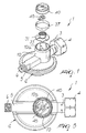
- the pressure regulator with pressure gauge particularly for LPG bottles, according to the invention, generally designated by the reference numeral 1, comprises a regulator body 2, of a per se known type, which is provided with an inlet 3 with a locking nut 4 and with an outlet 5 with a threaded portion 6.
- the pressure regulator has means for the connection of a pressure gauge, and the connection means have an outer side wall that is constituted by a cylindrical body 10 that is formed monolithically with the body 2.
- the outer side wall 10 forms internally a chamber 11 that is connected to the inlet 3.
- a shank 20, provided with a sealing O-ring 21, of a pressure gauge 30 can be inserted in chamber 11.
- the pressure gauge is advantageously constituted by a disk 31 above which a coil-type detector 32 is arranged, the detector being advantageously constituted by a Bourdon tube, which has a pointer 33 that can be positioned with respect to a scale 34 that is formed on the disk 31.
- the disk 31 is supported by radial ribs 35, which are formed on the inner surface of the side wall, and an elastic spacer ring 37 can be arranged above it; the ring is constituted by a lamina that is shaped like a split ring and is arranged so as to engage the peripheral rim of the disk 31 and be accommodated on the outside of a pressure gauge glass lens 40 on which there is an orientatable reference pointer 45 that allow to provide a reference element that can be positioned at will.
- the upper edge of the cylindrical side wall designated by the reference numeral 10a, can be folded over so as to engage above the elastic ring 37, which is retained in an axial direction and consequently keeps in position the pressure gauge by way of its engagement with the disk 31.
- the pressure gauge is integrated in the body of the regulator and is protected adequately.
- the materials used, as well as the contingent shapes and dimensions may be any according to requirements.
Landscapes
- Engineering & Computer Science (AREA)
- Mechanical Engineering (AREA)
- General Engineering & Computer Science (AREA)
- Chemical & Material Sciences (AREA)
- Combustion & Propulsion (AREA)
- Chemical Kinetics & Catalysis (AREA)
- General Chemical & Material Sciences (AREA)
- Oil, Petroleum & Natural Gas (AREA)
- Measuring Fluid Pressure (AREA)
- Filling Or Discharging Of Gas Storage Vessels (AREA)
- Control Of Fluid Pressure (AREA)
Abstract
Description
Claims (9)
- A pressure regulator (1) with pressure gauge, particularly for LPG bottles, which comprises a regulator body (2) that forms an inlet (3) and an outlet (5), means for connecting a pressure gauge being further provided, characterized in that said connection means form a chamber (11) for accommodating a pressure gauge (30), said chamber being formed by an outer side wall (10) that is formed monolithically with said body (2) of the regulator.
- The pressure regulator according to claim 1, characterized in that said outer side wall (10) is constituted by a cylindrical body that is monolithic with said regulator body (2).
- The pressure regulator according to the preceding claims, characterized in that said chamber (11) formed in said outer side wall (10) is connected to said inlet (3).
- The pressure regulator according to one or more of the preceding claims, characterized in that said pressure gauge (30) comprises a shank (20) that can be inserted hermetically in said chamber (11) and has a sealing O-ring (21).
- The pressure regulator according to one or more of the preceding claims, characterized in that said pressure gauge (30) comprises a disk (31) that supports axially said shank (20), which is in turn connected to a coil-type detector (32) constituted by a Bourdon tube.
- The pressure regulator according to claim 5, characterized in that said coil-type detector (32) has a pointer (33) that can be positioned with respect to a reference scale (34) provided on said disk (31).
- The pressure regulator according to one or more of the preceding claims, characterized in that it comprises, in said outer side wall (10), radial ribs (35) that act as a support for said disk (31).
- The pressure regulator according to one or more of the preceding claims, characterized in that it comprises an elastic spacer ring (37) that can engage said disk (31) peripherally and can engage the outside of a pressure gauge lens (40) that can be accommodated in said outer side wall (10), said elastic spacer ring (37) being retained in position by the folding of the free edge (10a) of said outer side wall (10).
- The pressure regulator according to one or more of the preceding claims, characterized in that said elastic spacer ring (37) is constituted by a lamina that forms a split ring.
Applications Claiming Priority (2)
| Application Number | Priority Date | Filing Date | Title |
|---|---|---|---|
| ITMI20030091 | 2003-01-22 | ||
| IT000091A ITMI20030091A1 (en) | 2003-01-22 | 2003-01-22 | PRESSURE REGULATOR WITH MANOMETER, PARTICULARLY FOR LPG CYLINDERS. |
Publications (2)
| Publication Number | Publication Date |
|---|---|
| EP1441273A1 true EP1441273A1 (en) | 2004-07-28 |
| EP1441273B1 EP1441273B1 (en) | 2006-06-28 |
Family
ID=32587883
Family Applications (1)
| Application Number | Title | Priority Date | Filing Date |
|---|---|---|---|
| EP03014464A Expired - Lifetime EP1441273B1 (en) | 2003-01-22 | 2003-07-01 | Pressure regulator with pressure gauge, particularly for LPG tanks |
Country Status (4)
| Country | Link |
|---|---|
| EP (1) | EP1441273B1 (en) |
| AT (1) | ATE331985T1 (en) |
| DE (1) | DE60306484T2 (en) |
| IT (1) | ITMI20030091A1 (en) |
Cited By (3)
| Publication number | Priority date | Publication date | Assignee | Title |
|---|---|---|---|---|
| LU91319B1 (en) * | 2007-02-26 | 2008-08-27 | Luxembourg Patent Co | Monobloc for gas with integrated pressure gauge |
| FR2999657A1 (en) * | 2012-12-13 | 2014-06-20 | Klever Energy Europ | Spark-ignition system for use in e.g. current generator, has connection arranged along with another connection, and third identical connection provided in connection with former connection that is connected to input of combustion chamber |
| CN104964162A (en) * | 2015-06-04 | 2015-10-07 | 江苏进源压力容器有限公司 | Pressure storage tank |
Families Citing this family (2)
| Publication number | Priority date | Publication date | Assignee | Title |
|---|---|---|---|---|
| DE102010003016B4 (en) * | 2010-03-18 | 2018-11-08 | Hyptec Gmbh | Pressure regulator for supplying fuel and fuel supply system with a control unit from these pressure regulators |
| US9709998B2 (en) | 2013-03-14 | 2017-07-18 | Marshall Excelsior Co. | Pressure regulator |
Citations (6)
| Publication number | Priority date | Publication date | Assignee | Title |
|---|---|---|---|---|
| US4176558A (en) * | 1978-03-17 | 1979-12-04 | Dresser Industries, Inc. | Pressure gauge casing-to-socket construction |
| US4860787A (en) * | 1986-01-15 | 1989-08-29 | Imaje, S.A. | Pressure regulator with integrated sensor |
| US5121637A (en) * | 1990-01-25 | 1992-06-16 | Union Carbide Canada Limited | Gas cylinder gauge |
| EP1054245A2 (en) * | 1999-05-18 | 2000-11-22 | Texas Instruments Incorporated | Capacitive pressure transducer having reduced output error |
| DE19947215A1 (en) * | 1999-10-01 | 2001-04-05 | Thomas Magnete Gmbh | Piloted shut-off valve has pushrod connected to axially movable slide sealed in housing of switching valve, and free end of slide is constructed as flange sealed in switching valve housing |
| EP1120561A2 (en) * | 2000-01-27 | 2001-08-01 | Landi Renzo S.p.A. | Two-stage pressure regulator for feeding internal combustion engines with gaseous fuel at constant pressure |
-
2003
- 2003-01-22 IT IT000091A patent/ITMI20030091A1/en unknown
- 2003-07-01 AT AT03014464T patent/ATE331985T1/en not_active IP Right Cessation
- 2003-07-01 DE DE60306484T patent/DE60306484T2/en not_active Expired - Lifetime
- 2003-07-01 EP EP03014464A patent/EP1441273B1/en not_active Expired - Lifetime
Patent Citations (6)
| Publication number | Priority date | Publication date | Assignee | Title |
|---|---|---|---|---|
| US4176558A (en) * | 1978-03-17 | 1979-12-04 | Dresser Industries, Inc. | Pressure gauge casing-to-socket construction |
| US4860787A (en) * | 1986-01-15 | 1989-08-29 | Imaje, S.A. | Pressure regulator with integrated sensor |
| US5121637A (en) * | 1990-01-25 | 1992-06-16 | Union Carbide Canada Limited | Gas cylinder gauge |
| EP1054245A2 (en) * | 1999-05-18 | 2000-11-22 | Texas Instruments Incorporated | Capacitive pressure transducer having reduced output error |
| DE19947215A1 (en) * | 1999-10-01 | 2001-04-05 | Thomas Magnete Gmbh | Piloted shut-off valve has pushrod connected to axially movable slide sealed in housing of switching valve, and free end of slide is constructed as flange sealed in switching valve housing |
| EP1120561A2 (en) * | 2000-01-27 | 2001-08-01 | Landi Renzo S.p.A. | Two-stage pressure regulator for feeding internal combustion engines with gaseous fuel at constant pressure |
Cited By (4)
| Publication number | Priority date | Publication date | Assignee | Title |
|---|---|---|---|---|
| LU91319B1 (en) * | 2007-02-26 | 2008-08-27 | Luxembourg Patent Co | Monobloc for gas with integrated pressure gauge |
| WO2008107311A1 (en) * | 2007-02-26 | 2008-09-12 | Luxembourg Patent Company S.A. | Single-piece gas fitting with built-in pressure gauge |
| FR2999657A1 (en) * | 2012-12-13 | 2014-06-20 | Klever Energy Europ | Spark-ignition system for use in e.g. current generator, has connection arranged along with another connection, and third identical connection provided in connection with former connection that is connected to input of combustion chamber |
| CN104964162A (en) * | 2015-06-04 | 2015-10-07 | 江苏进源压力容器有限公司 | Pressure storage tank |
Also Published As
| Publication number | Publication date |
|---|---|
| EP1441273B1 (en) | 2006-06-28 |
| ITMI20030091A1 (en) | 2004-07-23 |
| ATE331985T1 (en) | 2006-07-15 |
| DE60306484D1 (en) | 2006-08-10 |
| DE60306484T2 (en) | 2006-11-23 |
Similar Documents
| Publication | Publication Date | Title |
|---|---|---|
| US7240559B2 (en) | Manometer | |
| US4858776A (en) | Bottle closure assembly | |
| US9751689B2 (en) | Pressure vessel system and method | |
| EP1441273B1 (en) | Pressure regulator with pressure gauge, particularly for LPG tanks | |
| US8764284B2 (en) | Push button for timepiece incorporating a valve | |
| US20230332702A1 (en) | Check cover assemblies for backflow prevention assemblies with integrated test cock protection shroud | |
| US4051730A (en) | Condition responsive indicating instrument | |
| US20240381549A1 (en) | Venting unit for venting electronics housing | |
| AU2004203334A1 (en) | Flow control valve with device for indicating the status of a fluid, particularly for gas containers | |
| JPH07280134A (en) | Valve with open/close indicator device | |
| US20040011123A1 (en) | Pneumatic tire air pressure gauge assembly | |
| JP5942648B2 (en) | Detachable sealing device | |
| US20210317921A1 (en) | Safety valve and radiator using such safety valve | |
| KR20220155564A (en) | Liquid container having a gas exhaust means | |
| US4912965A (en) | Rupture disc monitor | |
| US7234858B2 (en) | Watch case | |
| EP1530002B1 (en) | Valve for containers of pressurized fluids with dirt blocking device | |
| JP2019020391A (en) | Safety valve for wristwatch | |
| US4214486A (en) | Sealed casing for pressure gauge | |
| US643519A (en) | Pressure-reducing valve. | |
| CN111913382B (en) | Stem-crown for a watertight watch case and watch case comprising such a stem-crown | |
| EP0026575A1 (en) | Pressure relief apparatus including valve and pressure indicator | |
| JP2008215573A (en) | Tank sealing device and method for assembling O-ring | |
| JP7262093B2 (en) | Open/close display device for wrench type on/off valve device, wrench type on/off valve device and cylinder container with valve | |
| JP5174157B2 (en) | Measuring device window |
Legal Events
| Date | Code | Title | Description |
|---|---|---|---|
| PUAI | Public reference made under article 153(3) epc to a published international application that has entered the european phase |
Free format text: ORIGINAL CODE: 0009012 |
|
| AK | Designated contracting states |
Kind code of ref document: A1 Designated state(s): AT BE BG CH CY CZ DE DK EE ES FI FR GB GR HU IE IT LI LU MC NL PT RO SE SI SK TR |
|
| AX | Request for extension of the european patent |
Extension state: AL LT LV MK |
|
| 17P | Request for examination filed |
Effective date: 20050111 |
|
| 17Q | First examination report despatched |
Effective date: 20050208 |
|
| AKX | Designation fees paid |
Designated state(s): AT BE BG CH CY CZ DE DK EE ES FI FR GB GR HU IE IT LI LU MC NL PT RO SE SI SK TR |
|
| GRAP | Despatch of communication of intention to grant a patent |
Free format text: ORIGINAL CODE: EPIDOSNIGR1 |
|
| GRAS | Grant fee paid |
Free format text: ORIGINAL CODE: EPIDOSNIGR3 |
|
| GRAA | (expected) grant |
Free format text: ORIGINAL CODE: 0009210 |
|
| AK | Designated contracting states |
Kind code of ref document: B1 Designated state(s): AT BE BG CH CY CZ DE DK EE ES FI FR GB GR HU IE IT LI LU MC NL PT RO SE SI SK TR |
|
| PG25 | Lapsed in a contracting state [announced via postgrant information from national office to epo] |
Ref country code: LI Free format text: LAPSE BECAUSE OF FAILURE TO SUBMIT A TRANSLATION OF THE DESCRIPTION OR TO PAY THE FEE WITHIN THE PRESCRIBED TIME-LIMIT Effective date: 20060628 Ref country code: CZ Free format text: LAPSE BECAUSE OF FAILURE TO SUBMIT A TRANSLATION OF THE DESCRIPTION OR TO PAY THE FEE WITHIN THE PRESCRIBED TIME-LIMIT Effective date: 20060628 Ref country code: SI Free format text: LAPSE BECAUSE OF FAILURE TO SUBMIT A TRANSLATION OF THE DESCRIPTION OR TO PAY THE FEE WITHIN THE PRESCRIBED TIME-LIMIT Effective date: 20060628 Ref country code: RO Free format text: LAPSE BECAUSE OF FAILURE TO SUBMIT A TRANSLATION OF THE DESCRIPTION OR TO PAY THE FEE WITHIN THE PRESCRIBED TIME-LIMIT Effective date: 20060628 Ref country code: FI Free format text: LAPSE BECAUSE OF FAILURE TO SUBMIT A TRANSLATION OF THE DESCRIPTION OR TO PAY THE FEE WITHIN THE PRESCRIBED TIME-LIMIT Effective date: 20060628 Ref country code: BE Free format text: LAPSE BECAUSE OF FAILURE TO SUBMIT A TRANSLATION OF THE DESCRIPTION OR TO PAY THE FEE WITHIN THE PRESCRIBED TIME-LIMIT Effective date: 20060628 Ref country code: NL Free format text: LAPSE BECAUSE OF FAILURE TO SUBMIT A TRANSLATION OF THE DESCRIPTION OR TO PAY THE FEE WITHIN THE PRESCRIBED TIME-LIMIT Effective date: 20060628 Ref country code: SK Free format text: LAPSE BECAUSE OF FAILURE TO SUBMIT A TRANSLATION OF THE DESCRIPTION OR TO PAY THE FEE WITHIN THE PRESCRIBED TIME-LIMIT Effective date: 20060628 Ref country code: AT Free format text: LAPSE BECAUSE OF FAILURE TO SUBMIT A TRANSLATION OF THE DESCRIPTION OR TO PAY THE FEE WITHIN THE PRESCRIBED TIME-LIMIT Effective date: 20060628 Ref country code: CH Free format text: LAPSE BECAUSE OF FAILURE TO SUBMIT A TRANSLATION OF THE DESCRIPTION OR TO PAY THE FEE WITHIN THE PRESCRIBED TIME-LIMIT Effective date: 20060628 |
|
| REG | Reference to a national code |
Ref country code: GB Ref legal event code: FG4D |
|
| REG | Reference to a national code |
Ref country code: CH Ref legal event code: EP |
|
| PG25 | Lapsed in a contracting state [announced via postgrant information from national office to epo] |
Ref country code: IE Free format text: LAPSE BECAUSE OF NON-PAYMENT OF DUE FEES Effective date: 20060703 |
|
| PG25 | Lapsed in a contracting state [announced via postgrant information from national office to epo] |
Ref country code: MC Free format text: LAPSE BECAUSE OF NON-PAYMENT OF DUE FEES Effective date: 20060731 |
|
| REG | Reference to a national code |
Ref country code: IE Ref legal event code: FG4D |
|
| REF | Corresponds to: |
Ref document number: 60306484 Country of ref document: DE Date of ref document: 20060810 Kind code of ref document: P |
|
| PG25 | Lapsed in a contracting state [announced via postgrant information from national office to epo] |
Ref country code: SE Free format text: LAPSE BECAUSE OF FAILURE TO SUBMIT A TRANSLATION OF THE DESCRIPTION OR TO PAY THE FEE WITHIN THE PRESCRIBED TIME-LIMIT Effective date: 20060928 Ref country code: DK Free format text: LAPSE BECAUSE OF FAILURE TO SUBMIT A TRANSLATION OF THE DESCRIPTION OR TO PAY THE FEE WITHIN THE PRESCRIBED TIME-LIMIT Effective date: 20060928 |
|
| PG25 | Lapsed in a contracting state [announced via postgrant information from national office to epo] |
Ref country code: ES Free format text: LAPSE BECAUSE OF FAILURE TO SUBMIT A TRANSLATION OF THE DESCRIPTION OR TO PAY THE FEE WITHIN THE PRESCRIBED TIME-LIMIT Effective date: 20061009 |
|
| PG25 | Lapsed in a contracting state [announced via postgrant information from national office to epo] |
Ref country code: PT Free format text: LAPSE BECAUSE OF FAILURE TO SUBMIT A TRANSLATION OF THE DESCRIPTION OR TO PAY THE FEE WITHIN THE PRESCRIBED TIME-LIMIT Effective date: 20061128 |
|
| NLV1 | Nl: lapsed or annulled due to failure to fulfill the requirements of art. 29p and 29m of the patents act | ||
| REG | Reference to a national code |
Ref country code: CH Ref legal event code: PL |
|
| PLBE | No opposition filed within time limit |
Free format text: ORIGINAL CODE: 0009261 |
|
| STAA | Information on the status of an ep patent application or granted ep patent |
Free format text: STATUS: NO OPPOSITION FILED WITHIN TIME LIMIT |
|
| EN | Fr: translation not filed | ||
| 26N | No opposition filed |
Effective date: 20070329 |
|
| GBPC | Gb: european patent ceased through non-payment of renewal fee |
Effective date: 20070701 |
|
| PG25 | Lapsed in a contracting state [announced via postgrant information from national office to epo] |
Ref country code: FR Free format text: LAPSE BECAUSE OF FAILURE TO SUBMIT A TRANSLATION OF THE DESCRIPTION OR TO PAY THE FEE WITHIN THE PRESCRIBED TIME-LIMIT Effective date: 20070511 Ref country code: GR Free format text: LAPSE BECAUSE OF FAILURE TO SUBMIT A TRANSLATION OF THE DESCRIPTION OR TO PAY THE FEE WITHIN THE PRESCRIBED TIME-LIMIT Effective date: 20060929 |
|
| PG25 | Lapsed in a contracting state [announced via postgrant information from national office to epo] |
Ref country code: GB Free format text: LAPSE BECAUSE OF NON-PAYMENT OF DUE FEES Effective date: 20070701 |
|
| PG25 | Lapsed in a contracting state [announced via postgrant information from national office to epo] |
Ref country code: EE Free format text: LAPSE BECAUSE OF FAILURE TO SUBMIT A TRANSLATION OF THE DESCRIPTION OR TO PAY THE FEE WITHIN THE PRESCRIBED TIME-LIMIT Effective date: 20060628 Ref country code: BG Free format text: LAPSE BECAUSE OF FAILURE TO SUBMIT A TRANSLATION OF THE DESCRIPTION OR TO PAY THE FEE WITHIN THE PRESCRIBED TIME-LIMIT Effective date: 20060928 |
|
| PG25 | Lapsed in a contracting state [announced via postgrant information from national office to epo] |
Ref country code: HU Free format text: LAPSE BECAUSE OF FAILURE TO SUBMIT A TRANSLATION OF THE DESCRIPTION OR TO PAY THE FEE WITHIN THE PRESCRIBED TIME-LIMIT Effective date: 20061229 Ref country code: LU Free format text: LAPSE BECAUSE OF NON-PAYMENT OF DUE FEES Effective date: 20060701 Ref country code: TR Free format text: LAPSE BECAUSE OF FAILURE TO SUBMIT A TRANSLATION OF THE DESCRIPTION OR TO PAY THE FEE WITHIN THE PRESCRIBED TIME-LIMIT Effective date: 20060628 |
|
| PG25 | Lapsed in a contracting state [announced via postgrant information from national office to epo] |
Ref country code: FR Free format text: LAPSE BECAUSE OF FAILURE TO SUBMIT A TRANSLATION OF THE DESCRIPTION OR TO PAY THE FEE WITHIN THE PRESCRIBED TIME-LIMIT Effective date: 20060731 |
|
| PG25 | Lapsed in a contracting state [announced via postgrant information from national office to epo] |
Ref country code: FR Free format text: LAPSE BECAUSE OF FAILURE TO SUBMIT A TRANSLATION OF THE DESCRIPTION OR TO PAY THE FEE WITHIN THE PRESCRIBED TIME-LIMIT Effective date: 20060628 Ref country code: CY Free format text: LAPSE BECAUSE OF FAILURE TO SUBMIT A TRANSLATION OF THE DESCRIPTION OR TO PAY THE FEE WITHIN THE PRESCRIBED TIME-LIMIT Effective date: 20060628 |
|
| REG | Reference to a national code |
Ref country code: DE Ref legal event code: R082 Ref document number: 60306484 Country of ref document: DE Representative=s name: GRAMM, LINS & PARTNER PATENT- UND RECHTSANWAEL, DE |
|
| PGFP | Annual fee paid to national office [announced via postgrant information from national office to epo] |
Ref country code: IT Payment date: 20180423 Year of fee payment: 16 |
|
| PG25 | Lapsed in a contracting state [announced via postgrant information from national office to epo] |
Ref country code: IT Free format text: LAPSE BECAUSE OF NON-PAYMENT OF DUE FEES Effective date: 20190701 |
|
| PGFP | Annual fee paid to national office [announced via postgrant information from national office to epo] |
Ref country code: DE Payment date: 20200728 Year of fee payment: 18 |
|
| REG | Reference to a national code |
Ref country code: DE Ref legal event code: R119 Ref document number: 60306484 Country of ref document: DE |
|
| PG25 | Lapsed in a contracting state [announced via postgrant information from national office to epo] |
Ref country code: DE Free format text: LAPSE BECAUSE OF NON-PAYMENT OF DUE FEES Effective date: 20220201 |