TECHNICAL FIELD
-
The present invention relates to a transmission screen
capable of preventing a deterioration of a display
characteristic generated therein causedby an ineffective flux
of light, and also relates to a projection display device using
the transmission screen.
BACKGROUND ART
-
A description will now be given of problems of
conventional transmission screens using various kinds of
Fresnel lens means such as a refraction Fresnel lens plate,
a total reflection Fresnel lens plate, and a refraction total
reflection Fresnel lens plate by referring to FIG.1 to FIG.3.
-
FIG.1 is a diagram showing a configuration and operation
of a conventional refraction Fresnel lens plate. FIG.1 shows
a shape of a cross section of the conventional refraction
Fresnel lens plate in which a refraction Fresnel plane is formed
at an incident side of a projected light flux. In FIG.1,
reference character 110A is a refraction Fresnel lens plate
(as refraction Fresnel lens means) , reference number 111
denotes a refraction inclined plane (as a refraction Fresnel
plane) , 112 indicates an ineffective facet plane (as a
refraction Fresnel plane) , and 115 designates an outgoing
plane. Reference character n designates a normal of the
refraction Fresnel lens plate 110A (or the outgoing plane 115) .
-
Reference number 150 designates a projected light flux
of the refraction Fresnel lens plate 110A, 152 denotes an
ineffective flux of light, 153 indicates an effective flux
of light. The refraction Fresnel lens plate 110A comprises
the refraction inclined plane 111 and the ineffective facet
plane 112 adjacent to the plane 111, which are formed in a
periodic structure.
-
Next, a description will now be given of the operation.
-
The projected light flux 150 enters in an angle to the
normal n of the refraction Fresnel lens plate 110A. A part
of the light flux 150 is refracted (in optical action) by the
refraction inclined plane 111 toward the direction of the normal
n, and outputs as an effective flux of light 153 from the outgoing
plane 115 of the refraction Fresnel lens plate110A.
-
On the other hand, the remaining part of the light flux
150 is refracted (in optical action) at the ineffective facet
plane 112 and becomes ineffective flux of light 152.
-
The ineffective flux of light 152 inclines to the normal
n, a part thereof outputs through the outgoing plane 115, and
another part thereof is reflected at the outgoing plane 115.
The ineffective flux of light 152 reflected at the outgoing
plane 115 enters the refraction inclined plane 111 or the
ineffective facet plane 112 again, which form the refraction
Fresnel lens plate 110A. The refraction and the reflection
of the ineffective flux of light 152 are repeated between the
refraction inclined plane 111 or the ineffective facet plane
112 and the outgoing plane 115.
-
The effective flux of light 153 in the above light fluxes
is a normal image light. The ineffective flux of light 152
causes the generation of a double image and a ghost image to
display spots and line images at incorrect display positions.
-
FIG.2 is a diagram showing the explanation of the
structure and the operation of the conventional total
reflection Fresnel lens plate. FIG.2 shows the shape of the
cross section of the total reflection Fresnel lens plate in
which the total reflection Fresnel plane is formed at the
incident side of the projected light flux. In FIG. 2, reference
character 110B is the total reflection Fresnel lens plate (total
reflection Fresnel lens means), reference number 113 denotes
a total reflection inclined plane (total reflection Fresnel
plane), 114 indicates a transmission inclined plane (total
reflection Fresnel plane), 115 denotes an outgoing plane, and
n indicates the normal of the total reflection Fresnel lens
plate 110B (or the outgoing plane 115).
-
Reference number 150 designates a projected light flux
to the total reflection Fresnel lens plate 110B, 151 denotes
an effective flux of light, and 152 designates a deviated flux
of light (as the ineffective flux of light).
-
The total reflection Fresnel lens plate 110B is made
up of a combination of the total reflection inclined plane
113 and the transmission inclined plane 114 adjacent to the
total reflection inclined plane 113 in a periodic structure.
-
Next, a description will now be given of the operation.
The projected light flux 150 enters at an angle to the normal
n of the total reflection Fresnel lens plate 110B, apart thereof
is refracted (in optical action) and then reflected (in optical
action) at the transmission inclinedplate 114 toward the normal
n at the total reflection inclined plane 113, and then outputs
as the effective flux of light 151 through the outgoing plate
115 of the total reflection Fresnel lens plate 110B.
-
On the other hand, the remaining part of the projected
light flux 150 becomes a deviated flux of light 152, not
reflected at the total reflection inclined plane 113.
-
The deviated flux of light 152 is inclined in direction
to the normal n. Apart thereof is output through the outgoing
plane 115, another part thereof is reflected at the outgoing
plane 115. Then, the deviated flux of light 152 reflected at
the outgoing plane 115 enters again into total reflection
inclinedplane 113 or the transmission inclinedplane 114 which
forms the total reflection Fresnel lens plate 110B.
-
The refraction and the reflection of the deviated flux
of light 152 are repeated between the total reflection inclined
plane 113 or the transmission inclined plane 114 and the
outgoing plane 115.
-
The effective flux of light 151 in the above light fluxes
is the normal image light. The deviated flux of light 152 causes
the generation of a double image and a ghost image which display
spots and line images at incorrect display positions.
-
FIG. 3 is a diagram showing a configuration and operation
of a conventional refraction total reflection Fresnel lens
plate. FIG.3 shows the configuration of the refraction total
reflection Fresnel lens plate in which both the refraction
Fresnel plane and the total reflection Fresnel plane are formed
at the incident plane of the projected light flux.
-
In FIG. 3, the same components of the configurations shown
in FIG.1 and FIG.2 will be referred to with the same reference
numbers and characters. In FIG.3, reference character 110C
designates the refraction total reflection Fresnel lens
(refraction total reflection Fresnel lens means).
-
Next, a description will now be given of the operation.
-
The projected light flux 150 enters in an angle to the
normal n of the refraction total reflection Fresnel lens plate
110C. The light flux refracted at the refraction inclined plane
111 becomes the effective fluxof light 153 which travels toward
the direction of the normal n. In addition, the light flux
refracted (in optical action) at the transmission inclined
plane 114 and then reflected (in optical action) at the total
reflection inclined plane 113 becomes the effective flux light
151 which travels to the normal n.
-
On the other hand, a projected light flux 150 and a
projected light flux 150, the former is refracted (in optical
action) at the ineffective facet plane 112 and the latter is
refracted (in optical action) and does not perform the total
reflection at the total reflection inclined plane 113, become
the ineffective flux of light (as a deviated flux of light)
152.
-
The ineffective flux of light 152 travels towards a
direction inclined relative to the normal n, and a part thereof
outputs through the outgoing plane 115, and another part is
reflected at the outgoing plane 115.
-
The ineffective flux of light 152 reflected at the
outgoing plane 115 enters again into the refraction inclined
plane 111, the ineffective facet plane 112, the total reflection
inclined plane 113, and the transmitting inclined plane 114
which form the refraction total reflection Fresnel lens plate
110C. The refraction and reflection are then performed for
the ineffective flux of light 152 between the refraction
inclined plane 111, the ineffective facet plane 112, the total
reflection inclinedplane 113, the transmission inclinedplane
114, and the outgoing plane 115.
-
The effective fluxes of light 151 and 153 in the above
light fluxes are the normal image light. The ineffective flux
of light 152 often causes a double image and a ghost image
which display a spot and a line image at positions different
from the normal display position.
-
In the configuration of the conventional transmission
screen, a lenticular lens plate (omitted from diagrams) is
arranged at the outgoing plane 115 side of the Fresnel lens
plate 110A, the total reflection Fresnel lens plate 110B, the
refraction total reflection Fresnel lens plate 110C shown in
FIG.1 to FIG.3 in order to control a geometric field angle
in a horizontal direction and an up-and-down direction and
to make the image.
-
Because the conventional transmission screen has the
configuration described above which generates the effective
flux light to contributes the display of the normal projected
image, it is difficult in principle to avoid the generation
of the ineffective flux of light which causes the phenomenon
of a double image and a ghost image. Therefore the conventional
transmission screen involves a problem in which the double
image and the ghost image overlap the normal projected image.
Because the generation of the double image and the ghost image
deteriorates a high image quality in display, there is a demand
to decrease the generation of the double image and the ghost
image.
-
The present invention is provided to solve the
above-described problems, and the object of the present
invention is to provide a transmission screen with a high image
quality capable of avoiding any generation of ineffective
fluxes of light and displaying the normal projected image only
using effective fluxes of light.
-
In addition, another object of the present invention
is to provide a projection display device capable of eliminating
any generation of a double image and a ghost image and of
displaying the image with a high quality.
DISCLOSURE OF INVENTION
-
In carrying out the invention and according to one aspect
thereof, there is provided a transmission screen having Fresnel
lens means, stray light eliminating means, and image display
means. The Fresnel lens means has a Fresnel surface molded
as an incident plane thereof for giving its optical action
to projected light fluxes and for outputting the light fluxes
through an outgoing plane thereof. The stray light eliminating
means eliminates a light flux having only a different angle
generated based on the optical action of the Fresnel surface.
The image display means scatters the light flux from the stray
light eliminating means and focuses the scattered one. It is
thereby possible to obtain the effect to provide the
transmission screen for eliminating ineffective light fluxes
and displaying only a normal projected image using effective
light fluxes with a high quality.
-
In the transmission screen according to the present
invention, the Fresnel lens means is refraction Fresnel lens
means having a refraction Fresnel plane formed at the incident
plane thereof, and the refraction Fresnel plane has refraction
inclined planes for refracting light fluxes, and ineffective
facet planes, which are arranged in a periodic structure. It
is thereby possible to obtain the effect to realize a highly
transmission efficiency in an area of small radius of the
Fresnel lens means.
-
In the transmission screen according to the present
invention, the Fresnel lens means is total reflection Fresnel
lens means having a total reflection Fresnel plane formed at
the incident plane thereof. The total reflection Fresnel plane
has transmission inclined planes for refracting light fluxes
and total reflection inclined planes for reflecting the light
fluxes refracted at the transmission inclined planes, which
are arranged in a periodic structure.
-
In the transmission screen according to the present
invention, the Fresnel lens means is refraction total
reflection Fresnel lens means has a refraction total reflection
Fresnel plane formed at the incident plane thereof. The
refraction total reflection Fresnel plane has refraction
inclinedplanes for refracting light fluxes, ineffective facet
planes, transmission inclined planes for refracting the light
fluxes, and total reflection inclined planes for reflecting
the light fluxes refracted at the transmission inclinedplanes ,
which are arranged in a periodic structure. It is thereby
possible to obtain the effect to realize a highly transmission
efficiency in an area of a small radius of the Fresnel lens
means.
-
In the transmission screen according to the present
invention, the refraction inclined planes in the Fresnel lens
means refract the projected light fluxes toward a direction
approximately parallel to a normal of the outgoing plane of
the Fresnel lens means. It is thereby possible to obtain the
effect to form the display image of a light distribution
characteristic of symmetry to the direction of the normal of
the transmission screen and to display the display image for
an observer at the center of the transmission screen under
the optimum condition.
-
In the transmission screen according to the present
invention, the total reflection inclined planes in the Fresnel
lens means reflect the light fluxes refracted at the
transmission inclined planes toward a direction approximately
parallel to a normal of the outgoing plane of the Fresnel lens
means. It is thereby possible to obtain the effect to form
the display image of a light distribution characteristic of
symmetry to the direction of the normal of the transmission
screen and to display the display image for an observer at
the center of the transmission screen under the optimum
condition.
-
In the transmission screen according to the present
invention, the refraction inclined planes in the Fresnel lens
means refract the projected light fluxes toward a direction
approximately parallel to a normal of the outgoing plane of
the Fresnel lens means. The total reflection inclined planes
in the Fresnel lens means reflect the light fluxes refracted
at the transmission inclined planes toward the direction
approximately parallel to the normal of the outgoing plane
of the Fresnel lens means. It is thereby possible to obtain
the effect to form the display image of a light distribution
characteristic of symmetry to the direction of the normal of
the transmission screen and to display the display image for
an observer at the center of the transmission screen under
the optimum condition.
-
In the transmission screen according to the present
invention, the Fresnel lens means changes a ratio of a total
reflection Fresnel section and a refraction Fresnel section,
and the total reflection Fresnel section is composed of the
transmission inclinedplanes and the total reflection inclined
planes and the refraction Fresnel section is composed of the
refraction inclined planes and the ineffective facet planes
according to a distance measured from a center of its rotation.
It is thereby possible to obtain the effect to further increase
the transmission efficiency.
-
In the transmission screen according to the present
invention, the stray light eliminating means has condensing
light lens array means and first black stripe means. In the
condensing light lens array means, unit lenses are arranged
at an incident plane of a first transmission substrate in a
periodic structure in an up-and-down direction. The firstblack
stripe means is composed of transparent sections placed near
a condensing light point of each unit lens and opaque sections
placed at a peripheral area of the condensing light point of
each unit lens, which are arranged alternately at the outgoing
plane of the first transparent substrate in a periodic structure
in an up-and-down direction. It is thereby possible to obtain
the effect to provide the transmission screen capable of
eliminating the ineffective flux of light and of displaying
the normal projected image only using the effective flux of
light with a high quality.
-
In the transmission screen according to the present
invention, the image display means is lenticular lens means
having the unit lenses arranged in a periodic structure in
a horizontal direction at an outgoing plane of a second
transparent substrate having a scattering characteristic
capable of scattering the light fluxes. It is thereby possible
to obtain the effect to scatter the image light fluxes by a
simple configuration in order to make the image.
-
In the transmission screen according to the present
invention, the stray light eliminating means has holding
transmission substrate for holding the first transmission
substrate, the condensing light lens arraymeans; and the first
black stripe means. It is thereby possible to obtain the effect
to form the stray light eliminating means even if the layer
of each of the first transmission substrate and the condensing
light lens array means is thin.
-
In the transmission screen according to the present
invention, the stray light eliminating means has the condensing
light lens array means and the first black stripe means, which
are molded with a concentric circle shape around a center of
rotation of the Fresnel lens means. It is thereby possible
to obtain the effect to further exert the function of the stray
light eliminating means capable of eliminating ineffective
flux of light.
-
In the transmission screen according to the present
invention, the stray light eliminatingmeans has the condensing
light lens array means and the first black stripe means, which
are molded with a periodic structure of a line shape. It is
thereby possible to obtain the effect to greatly release the
limit from the manufacture of the stray light eliminating means
and to display the good image with a low manufacturing cost.
-
In the transmission screen according to the present
invention, the stray light eliminating means has one of the
first transmission substrate having a scattering
characteristic and the condensing light lens array means having
the scattering characteristic. It is thereby possible to obtain
the effect to prevent a deterioration of the projected image
which is caused by the image light fluxes based on
scintillation.
-
In the transmission screen according to the present
invention, the image display means has second black stripe
means in which transparent sections and opaque sections are
arranged at the outgoing plane of a third transparent substrate
alternately in a periodic structure in a horizontal direction,
the transparent sections are placed near the condensing light
point of each unit lens in the lenticular lens means, and the
opaque sections are placed at a peripheral area of the
condensing light point of each unit lens. It is therebypossible
to obtain the effect to eliminate the components in an
up-and-down direction and a horizontal direction and to
eliminate the occurrence of a double image and a ghost image.
-
In the transmission screen according to the present
invention, the stray light eliminating means has transparent
sections through which the light fluxes pass, horizontal louver
shaped opaque sections arranged in a periodic structure in
an up-and-down direction between the transparent sections,
and up-and-down louver shaped opaque sections arranged in a
periodic structure in a horizontal direction between the
transparent sections. It is thereby possible to obtain the
effect to eliminate the components in an up-and-down direction
and a horizontal direction and to eliminate the occurrence
of a double image and a ghost image.
-
In the transmission screen according to the present
invention, the stray light eliminating means has transparent
sections through which the light fluxes pass, and a horizontal
louver shaped opaque sections arranged in a periodic structure
in an up-and-down direction between the transparent sections.
The image display means has second black stripe means in which
transparent sections and opaque sections are arranged at the
outgoing plane of a third transparent substrate alternately
in a periodic structure in a horizontal direction. The
transparent sections are placed near the condensing light point
of each unit lens in the lenticular lens means. The opaque
sections are placed at a peripheral area of the condensing
light point of each unit lens. It is thereby possible to obtain
the effect to eliminate the components in an up-and-down
direction and a horizontal direction and to eliminate the
occurrence of a double image and a ghost image.
-
In the transmission screen according to the present
invention, the louver shaped opaque section in the stray light
eliminating means has a cross section so that a width of the
louver shaped opaque section is changed along the direction
of the normal of the outgoing plane of the Fresnel lens means.
It is thereby possible to obtain the effect to easily mold
the stray light eliminating means and to inject a Chinese ink
or an ink of another type as the louver shaped opaque section.
-
In the transmission screen according to the present
invention, the louver shaped opaque section in the stray light
eliminating means has a cross section so that a width of the
louver shaped opaque section is changed along the direction
of the normal of the outgoing plane of the Fresnel lens means.
It is thereby possible to obtain the effect to easily mold
the stray light eliminating means and to inject a Chinese ink
or another ink as the louver shaped opaque section.
-
In the transmission screen according to the present
invention, the stray light eliminating means is formed in one
body on the outgoing plane of the Fresnel lens means. It is
thereby possible to obtain the effect to suppress the generation
of a reflected ineffective flux of light generated at the
outgoing plane of the Fresnel lens means to the minimum state.
-
In the transmission screen according to the present
invention, the stray light eliminating means is formed in one
body on the outgoing plane of the Fresnel lens means. It is
thereby possible to obtain the effect to suppress the generation
of a reflected ineffective flux of light generated at the
outgoing plane of the Fresnel lens means to the minimum state.
-
A projection display device according to the present
invention has a transmission screen and a projection optical
system for projecting light fluxes to the transmission screen
in order to focus an image on the transmission screen. The
transmission screen has Fresnel lens means, stray light
eliminating means, and image display means. The Fresnel lens
means has a Fresnel surface molded at an incident plane thereof
for giving its optical action to projected light fluxes and
for outputting the light fluxes through its outgoing plane.
The stray light eliminating means eliminates a light flux having
only a different angle generated based on the optical action
of the Fresnel surface. The image display means scatters the
light flux from the stray light eliminating means to make the
scattered one. It is thereby possible to effect to provide
the projection display device capable of eliminating any
occurrence of the generation of a double image and a ghost
image and of displaying a high quality image.
BRIEF DESCRIPTION OF DRAWINGS
-
- FIG.1 is a diagram to explain a configuration and
operation of a conventional refraction Fresnel lens plate.
- FIG.2 is a diagram to explain a configuration and
operation of a conventional total reflection Fresnel lens
plate.
- FIG.3 is a diagram to explain a configuration and
operation of a conventional refraction total reflection
Fresnel lens plate.
- FIG.4 is a diagram showing a configuration of a cross
section of a transmission screen in an up-and-down direction
according to a first embodiment of the present invention.
- FIG.5 is a diagram showing a configuration of the
transmission screen observed from an oblique direction
according to the first embodiment of the present invention.
- FIG. 6A and FIG.6B are diagrams showing a configuration
of a transmission screen according to a second embodiment of
the present invention.
- FIG. 7A and FIG.7B are diagrams showing a configuration
of a transmission screen according to a third embodiment of
the present invention.
- FIG.8A to FIG.8C are diagrams showing a configuration
of a transmission screen according to a fourth embodiment of
the present invention.
-
BEST MODE FOR CARRYING OUT THE INVENTION
-
The best mode for carrying out the invention will now
be described in detail by referring to the accompanying
drawings.
First Embodiment
-
FIG.4 is a diagram showing a configuration of a cross
section of a transmission screen in an up-and-down direction
according to a first embodiment of the present invention. FIG. 5
is a diagram showing a configuration of the transmission screen
observed from an oblique direction according to the first
embodiment of the present invention.
-
In FIG.4, reference character 10C designates a
refraction total reflection Fresnel lens plate (refraction
total reflection Fresnel lens means) , reference number 20
denotes a stray light eliminating plate (stray light
eliminating means), and 30 indicates an image display plate
(image display means) . The transmission screen comprises the
refraction total reflection Fresnel lens plate 10C, the stray
light eliminating plate 20, and the image display plate 30.
Reference character n designates the normal which is the common
one for the refraction total reflection Fresnel lens plate
10C, the stray light eliminating plate 20, and the image display
plate 30. In FIG.5, reference number 40 designates a projection
optical system to output a projected light flux 50, and 90
indicates an observer who watches an enlarged display image.
-
Next, a description will now be given of the operation.
-
A part of a projected light flux 50, which is output
from the projection optical system 40 and input to the
refraction total reflection Fresnel lens plate 10C inclined
to the normal n, is refracted at the refraction inclined plane
11 placed at the incident plane of the refraction total
reflection Fresnel lens plate 10C and becomes an effective
flux of light 53 which is parallel to the normal n. Another
part of the projected light flux 50 is refracted at the
transmission inclined plane 14, then reflected at the total
reflection inclined plane 13 so as to become the effective
flux of light 51 in parallel to the normal n.
-
The remaining part of the projected light flux 50 other
than the above light fluxes is refracted at the ineffective
facet plane 12 adjacent in position to the refraction inclined
plane 11, or becomes the ineffective flux of light 52 (a deviated
flux of light) which is inclined to the normal n after it is
refracted at the transmission inclined plane 14 and not
reflected at the total reflection inclined plane 13. In both
the cases, the remaining part of the projected light flux 50
then enters the outgoing plane 15.
-
The stray light eliminating plate 20 is made up of a
condensing light lens array 21 (condensing light lens array
means) formed at the incident plane side of a transmission
substrate 22 (first transmission substrate) and black stripes
23 (first black stripe means) formed at the side of the outgoing
plane of the transmission substrate 22.
-
Like the typical configuration shown in FIG.5, both
the condensing light lens array 21 and the black stripe 23
are made up of a lens array in periodically formed in an
up-and-down direction and transparent/opaque lattice plates.
-
The black stripe 23 is made up of the transparent sections
201 close to the condensing point of each unit lens forming
the condensing light lens array 21 and the opaque sections
200 at surrounding area of the condensing point in periodic
configuration.
-
In FIG.4, the effective fluxes 51 and 53 of light
deflected at the refraction total reflection Fresnel lens plate
10C in direction along the normal n inputs into the condensing
light lens array 21, and condensed to an area close to the
focus of the lens unit of the condensing light lens array 21,
travels through the transparent sections 201 and becomes the
effective outgoing light 55. The effective outgoing light 55
is finally input to the image display plate 30. In order to
achieve this process, the center of each unit lens of the
condensing light lens array 21 and the center of each
transparent section 201 are approximately equal in position,
as shown in FIG.4 showing a sectional configuration.
A lenticular lens 31 (cylindrical lens array and lenticular
lens means) is formed in periodic pattern along a horizontal
direction at the incident plane of the image display plate
30.
-
In addition, the transmission substrate 32 (second
transmission substrate) is mounted at the outgoing plane side
of the image display plate 30 in order to hold the lenticular
lens 31. The lenticular lens 31 has a function to spread the
incident light in horizontal direction.
-
Conventional scatteringparticles are held in the inside
or the area close to the surface of the transmission substrate
32.
-
The transmission substrate 32 acts as the spreading plate
in order to focus the projected image. Accordingly, a light
distribution characteristic of the image light flux 80 in
horizontal direction output from the transmission screen is
determined based on the refraction power of the lenticular
lens 31 and the scattering characteristic of the transmission
substrate 32. The light distribution characteristic of the
image light flux 80 in an up-and-down direction is determined
based on the refraction power of the stray light eliminating
plate 20 and the scattering characteristic of the transmission
substrate 32.
-
Because both the effective fluxes 51 and 53 of light
is deflected in direction along the normal n by the refraction
inclined plane 11 and the total reflection inclined plane 13,
-
The image flux 80 output from the transmission screen
has a light distribution characteristic with a good symmetry
to the normal n, so that the observer 90 at the front position
of the transmission screen can watch the image easily.
-
Next, a description will now be given of the eliminating
method of the ineffective flux of light from the stray light
eliminating plate 20.
-
The ineffective flux of light 52 generated at the
refraction total reflection Fresnel lens plate 10C is input
into the stray light eliminating plate 20 through the outgoing
plane 15 while keeping it in the inclined state to the normal
n. After the ineffective flux of light 52 is reflected at the
outgoingplane 15 as the reflected ineffective flux 54 of light,
it is refracted and reflected again by the refraction inclined
plane 11, the ineffective facet plane 12, the total reflection
inclined plane 13, and the transmission inclined plane 14 placed
at the incident plane side of the refraction total reflection
Fresnel lens plate 10C. A part of the light fluxes travels
through the outgoing plate 15 and then input into the stray
light eliminating plate 20 again as the ineffective light flux.
-
According to a detailed light tracing simulation, it
is clear that a large part of the ineffective flux of light
which is input again is a light flux greatly inclined to the
normal n.
-
The ineffective flux 52 of light (including the re-input
ineffective flux of light) which enters to the stray light
eliminating plate 20 in an inclined direction to the normal
n is absorbed by the opaque sections 200 of the black stripe
23 after passing through the condensing light lens array 21.
Accordingly, it is possible to prevent to input it to the image
display plate 30. Thereby, it is possible to greatly improve
the conventional problems to eliminate the occurrences of the
double image and the ghost image caused by the ineffective
flux 52 of light.
-
The opaque sections 200 is formed by selecting
application and patterning of well-known various kinds of black
colorpaints, by selecting rough surface working of the outgoing
plane of the transmission substrate 22 or a combination of
those processes.
-
The eliminating function to eliminate the ineffective
flux of light by the stray light eliminating plate 20 used
in the present invention is achieved using the condensing light
lens array 21 and the black stripes 23 formed in a periodic
pattern in an up-and-down direction. Therefore it is possible
that the stray light eliminating plate 20 having this function
acts the ideal operation when the axis of rotation of the
refraction total reflection Fresnel lens plate 10C is
positioned on the center line of the right section and the
left section of the transmission screen.
-
Further, the condensing light lens array 21 and the black
stripes 23 are formed in a concentric configuration and a
periodic structure about the center of rotation of the
refraction total reflection Fresnel lens plate 10C, it is
possible to effectively execute the eliminating function to
eliminate the ineffective flux of light of the stray light
eliminating plate 20.
-
In an ideal case, the shading function of the stray light
eliminating plate 20 is originally used when the transmission
substrate 22 and the condensing light lens array 21 do not
have any scattering function. In an usual case, the elements
are arranged so that the transmission substrate 32 mainly shares
the scattering function to make image. However, it is possible
to control the light distribution characteristic and the
imaging action for the outgoing light from the transmission
screen by adding the scattering function to the transmission
substrate 22 and the condensing light lens array 21 as the
components forming the stray light eliminating plate 20.
-
For example, there is an effective example to prevent
the deterioration of the projected image caused by
scintillation generated in the image light flux 80. In this
example a simple scattering characteristic is applied to
configuration materials forming the transmission substrate
22 and the condensing light lens array 21 by adding some fine
particles to them. By this manner, the scattering function
is distributed in the direction of the normal n of the
transmission screen in addition to the scattering function
of the transmission substrate 32 which is separated in distance
from the stray light eliminating plate 20. It is therefore
a design choice of a system design of the projection display
device for the configuration elements of the stray light
eliminating plate 20.
-
Further, when the thickness of the stray light
eliminating plate 20 made up of the lens array 21, the
transmission substrate 22, and the black stripes 23 is thin
and difficult to hold the plate 20 itself, a transmission
substrate 24 (a holding transmission substrate) is mounted,
as shown by dotted lines in FIG.4.
-
Still further, the inventors of the present invention
have observed a projected image using the transmission screen
having another configuration in which the stray light
eliminating plate 20 is combined to the refraction total
reflection Fresnel lens plate 10C. This stray light eliminating
plate 20 is composed of line-shaped black stripes 23 of a
periodic form in an up-and-down direction, like the case of
the line-shaped condensing lens array 21 of the periodic form
in an up-and-down direction shown in FIG.5. The refraction
total reflection Fresnel lens plate 10C is placed on the center
line of the transmission screen and under the downstream side
of the transmission screen.
-
From a result of the above observation, it is recognized
to reduce the occurrence of the double image and the ghost
image, overlapped on the display image, around the area in
an up-and-down direction through the center of the image.
Although the stray light eliminating plate 20 must be formed
in a concentric circle structure to the center of the refraction
total reflection Fresnel lens in an ideal case, the result
of the above observation means that it is possible to obtain
the image quality improvement effect of not less than a constant
level even if the stray light eliminating plate 20 is replaced
with the stray light eliminating plate made up of the condensing
light lens array of the straight-line stripe structure and
the black stripe. This replacement with the stray light
eliminating plate greatly relaxes the limitation in structure
of the stray light eliminating plate. It is thereby possible
to provide the transmission screen capable of displaying a
good image with a low cost.
-
As described above, according to the first embodiment,
the transmission screen has the refraction total reflection
Fresnel lens plate 10C, the condensing lens array 21, the
transparent sections 201, the stray light eliminating plate
20, and the image display plate 30.
-
The optical action of the refraction total reflection
Fresnel lens plate 10C processes the projected light 50 and
outputs theprocessedone through theoutgoingplane 15 thereof.
The condensing light lens array 21 is composed of the unit
lenses arranged of a periodic structure in an up-and-down
direction at the incident plane of the transmission substrate
22.
-
The transparent sections 201 are mounted at the area
close to the focus point of each unit lens.
-
The stray light eliminating plate 20 is composed of the
opaque sections 200 formed close to the condensing light point
of each unit lens and the black stripes 23 arranged alternately
to each other in a periodic structure in an up-and-down
direction at the outgoing plane of the transmission substrate
22.
-
The image displayplate 30 is composed of the lenticular
lens 31 having the unit lenses in periodic pattern in horizontal
direction on the incident plane of the transmission substrate
32 which scatters the light flux based on its scattering
characteristic. It is thereby possible to provide the
transmission screen capable of displaying the normal projected
image with a high quality only using the effective light fluxes
51 and 53.
-
In addition, according to the first embodiment, the
refraction inclined plane 11 in the refraction total reflection
Fresnel lens plate 10C refracts the projected light flux 50
toward approximately parallel direction to the normal n of
the outgoing plane 15. The total reflection inclined plane
13 on the refraction total reflection Fresnel lens plate 10C
reflects the light flux refracted at the transmission inclined
plane 14 toward the approximately parallel direction to the
normal n of the outgoing plane 15. It is thereby possible to
form the display image of a light distribution characteristic
of symmetry to the normal n of the transmission screen, and
to display the image with the optimum condition to the observer
90 positioned at the center of the transmission screen.
-
Still further, according to the first embodiment, the
stray light eliminating plate 20 has the transmission substrate
24 to hold the transmission substrate 22, the condensing light
lens array 21, and the black stripes 23. It is possible to
obtain the effect to form the stray light eliminating plate
20 even if the thickness of the layer composed of the
transmission substrate 22, the condensing light lens array
21, and the black stripes 23 is thin.
-
Furthermore, according to the first embodiment, the
stray light eliminating plate 20 has the condensing light lens
array and the first black stripes molded with a periodic
structure in a concentric circle to the center of rotation
of the Fresnel lens plate 10C. It is thereby possible to obtain
the effect that the stray light eliminating plate 20 can perform
its ineffective light flux eliminating function more
effectively.
-
Still furthermore, according to the first embodiment,
the stray light eliminating plate 20 has the condensing light
lens array and the first black stripes molded in a periodic
structure of a straight-line shaped. It is thereby possible
to obtain the effect to greatly relax the limitation of the
manufacturing for the stray light eliminating plate 20 and
to display the good image with a low cost.
-
Moreover, according to the first embodiment, the stray
light eliminating plate 20 has the transmission substrate 22
with the scattering characteristic and the condensing light
lens array 21 with the scattering characteristic. It is possible
to obtain the effect to prevent the deterioration of the
projected image caused by the scintillation generated in the
projected image 80.
-
Still moreover, according to the first embodiment, the
projection display device has the projection optical system
40 todisplay the image on the transmission screenbyprojecting
the projected light flux 50 to the transmission screen. The
embodiment has the effect that it is possible to provide the
projection display device capable of displaying high quality
images by eliminating the occurrence of the double image and
the ghost image.
SECOND EMBODIMENT
-
The second embodiment shows how to reduce the occurrence
of a double image and a ghost image generated in a wide area
including the projected image area.
-
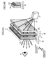
FIG.6A and FIG.6B are diagrams showing a structure of
the transmission screen according to the second embodiment
of thepresentinvention. In FIG. 6A and FIG. 6B, reference number
33 designates a transmission substrate (a third transmission
substrate), and 34 denotes black stripes (second black stripe
means). In FIG. 6, the image display plate 30 has the function
to eliminate the horizontal component of the ineffective flux
of light, instead of the stray light eliminating plate 20.
In order to achieve this feature, the black stripes 34 and
the transmission substrate 33 are placed between the lenticular
lens 31 and the transmission substrate 32 of the periodic
pattern in horizontal direction. Because other components are
the same as those of the case shown in FIG.4 and FIG.5, the
explanation for the same configuration is omitted here.
-
FIG.6B shows an enlarged view of the image display plate
30 shown in FIG.6A.
-
In order to form the projected image, like the case of
the first embodiment shown in FIG.5, scattering particles are
dispersed and held in the internal area or at the area around
the surface of the transmission substrate 32. This
configuration gives the scattering characteristic to the
transmission substrate 32. The lenticular lens 31 is a
cylindrical shaped lens array which draws in an up-and-down
direction and has a periodic pattern in horizontal direction.
-
Further, the black stripes 34 has the periodic structure
in horizontal direction so that the opaque sections 300 are
shifted from the center of the lens by matching the transparent
section 301 to the center of each unit lens of the lenticular
lens 31. Further, the opaque sections 300 has been made by
one of or a combination of a well-known selective application
for each kind of black color prints, a patterning, and a
selective rough surface work for the surface of the outgoing
side of the transmission substrate 33.
-
The black stripes 34 and the lenticular lens 31 are held
with a desired distance between the transmission substrate
33 and the black stripes 34 are bonded to the transmission
substrate 32.
-
The formation of the image display plate 30 with the
above described manner can achieve that the image display plate
30 has the function to eliminate the ineffective flux of light
in horizontal direction based on the same principle of the
stray light eliminating plate 20 shown in FIG.5.
-
When the symmetric axis of rotation is on the center
line of the transmission screen and the refraction total
reflection Fresnel lens plate 10C is placed at the area close
to the lower section of the transmission screen, the stray
light eliminating plate 20 can eliminate the ineffective flux
of light generated in the up-and-down direction of the area
close to the center section in the horizontal direction of
the transmission screen. The combination of the stray light
eliminating plate 20 and the image display plate 30 can
eliminate the ineffective flux of light generated in an inclined
direction of the area outside of the center of the transmission
screen in right and left directions. It is thereby possible
to more strictly eliminate the double image and the ghost image
when compared with the case shown in FIG.4 and FIG.5.
-
As described above, according to the second embodiment,
the image display plate 30 has the black stripes 34 formed
between the transmission substrate 32 and the lenticular lens
31. The black stripes 34 are so formed that the transparent
sections 301 and the opaque sections 300 are alternately formed
at the outgoing plane of the transmission substrate 33 in a
periodic pattern in the horizontal direction. The black stripes
34 are formed at the area close to the condensing point of
each unit lens of the lenticular lens 31. The opaque sections
300 are formed at the peripheral area of the condensing point
of each unit lens. This configuration has the effect to
eliminate the components in an up-and-down direction and the
horizontal direction of the ineffective flux of light 52. It
is thereby possible to eliminate the double image and the ghost
image more strictly.
Third embodiment
-
A third embodiment will explain a modification example
of the configuration of the transmission screen capable of
eliminating both the components in an up-and-down direction
and a horizontal direction of the ineffective flux of light,
like the case of the second embodiment.
-
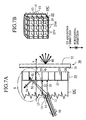
FIG. 7A and FIG.7B are diagrams showing a configuration
of the transmission screen of the third embodiment of the
present invention.
-
In FIG.7A, reference character 10C designates a
refraction total reflection Fresnel lens plate like that shown
in FIG. 4, reference number 20 denotes a stray light eliminating
plate placed at the outgoing plane 15 side of the refraction
total reflection Fresnel lens plate 10C, and 26 indicates
transparent sections of the stray light eliminating plate 20.
-
Reference number 25 designates louver shaped opaque
sections in the stray light eliminating plate 20, and 55 denotes
an effective outgoing light flux of the stray light eliminating
plate 20. The image display plate 30 has the same configuration
shown in FIG.4. Further, FIG. 7B shows an enlarged oblique view
of the stray light eliminating plate 20 and the refraction
total reflection Fresnel lens plate 10C observed from the
effective outgoing light flux 55 side. In this enlarged oblique
view, reference character 25H designates the louver shaped
opaque sections in a horizontal direction, which are arranged
in a periodic form in an up-and-down direction between the
transparent sections 26. Reference character 25V denotes the
louver shaped opaque sections in an up-and-down direction
formed in a periodic pattern between the transparent sections
26 in the horizontal section.
-
Next, a description will now be given of the operation
of the transmission screen shown in FIG.7.
-
In the same manner shown in FIG.4, by the refraction
action of the refraction inclined plane 11 and the actions
of the transmission inclined plane 14, and the total reflection
inclined plane 13, a projected light flux 50 becomes the
effective fluxes 53 and51 of lightwhich travel in thedirection
of the normal n of the transmission screen. The effective fluxes
53 and 51 of light pass through the transparent sections 26
and input as the effective outgoing light fluxes 55 into the
image display plate 30. The light fluxes 55 are scattered by
the lenticular lens 31 in a horizontal direction and the
scattered light fluxes are then displayed as the projected
image on the transmission substrate 32 having the scattering
characteristic.
-
A light distribution characteristic of the image light
flux 80 in a horizontal direction is determined based on the
scattering characteristic of the lenticular lens 31 in an
horizontal direction and the scattering characteristic of the
transmission substrate 32.
-
The arrow with dotted lines designated by reference
number 52 indicates an ineffective flux of light passed through
the ineffective facet plane 12 of the refraction total
reflection Fresnel lens plate 10C or an ineffective flux of
light which is not reflected by the total reflection inclined
plane 13 after passed through the transmission inclined plane
14.
-
This ineffective flux of light 52 is absorbed by the
louver shaped opaque sections 25 placed along the direction
of the normal n, or which becomes the reflected ineffective
flux of light 54 after it is reflected at the boundary surface
of the refraction total reflection Fresnel lens plate 10C and
the stray light eliminating plate 20. After this, the reflected
ineffective flux of light 54 at the boundary surface 15 is
refracted and reflected by the refraction inclined plane 11,
the ineffective facet plane 12, the total reflection inclined
plane 13, the transmission inclined plane 14 at the incident
side of the refraction total reflection Fresnel lens plate
10C, and then enters again into the boundary surface 15, and
a large part thereof is absorbed by the louver shaped opaque
section 52.
-
It is not necessary to consider any generation of the
refracted ineffective light flux 54 because the boundary
surface 15 seldom generates the reflection ineffective flux
of light 54 in cases where the stray light eliminating plate
20 is formed in one body on the bottom surface (as the outgoing
plane) of the refraction total reflection Fresnel lens plate
10C or both are bonded with an adhesive material.
-
It is possible to form the stray light eliminating plate
20 using acryl material, for example, lattice shaped grooves
are formed using a die in which projecting rows corresponding
to the louver shaped opaque sections 25 are formed and a Chinese
ink or another ink with an absorptive property is then poured
into the groove sections.
-
When the Chinese ink or another ink is poured, dusts
remained on the surface of the stray light eliminating plate
20 are eliminated as necessary in order to keep the transmission
characteristic of the transparent sections 26.
-
The stray light eliminating plate 20 formed by the above
manner is bounded in one body onto the refraction total
reflection Fresnel lens plate 10C made up of acryl material
with an adhesive material having a same refraction index of
the acryl material, for example. It is thereby possible to
minimize the generation of the reflected ineffective flux of
light 54. It is of course acceptable to form it by making of
one piece the stray light eliminating plate 20 directly on
the bottom surface of the refraction total reflection Fresnel
lens plate 10C and then by injecting the Chinese ink or another
ink into it.
-
Although FIG.7A shows the sectional view of the
transmission screen in an up-and-down direction, theprojected
light flux 50 has an inclined component and a horizontal
component. In this case, the horizontal component of the
ineffective flux of light generated is mainly absorbed by the
louver shaped opaque sections 25V in an up-and-down direction.
In addition, the component of the ineffective flux of light
in the up-and-down direction is mainly absorbed by the louver
shaped opaque sections 25H in the horizontal direction
-
It is also acceptable for the louver shaped opaque
sections 25, 25V, and 25H to have a shape whose width is gradually
changed toward the direction of the normal n in consideration
of an easily pattern-molding characteristic and an easy
injecting characteristic of the Chinese ink or an ink of another
type.
-
In thi s case, the louver shaped opaque sections 25 become
a trapezoidal shape (omitted from the diagram) whose width
is gradually changed toward the normal n in the sectional view
of the transmission screen shown in FIG.7A.
-
As described above, according to the third embodiment,
the stray light eliminating plate 20 is composed of the
transparent sections 26 which transmit light fluxes, the louver
shaped opaque sections 25H in an horizontal direction arranged
between the transparent sections 26 in a periodic structure
in an up-and-down direction, and the louver shaped opaque
sections 25V in an up-and-down direction arranged between the
transparent sections 26 in a periodic structure in a horizontal
direction. It is thereby possible to eliminate the components
of the ineffective flux of light 52 in the up-and-down direction
and in the horizontal direction. This can obtain the effect
to eliminate the double image and the ghost image more strictly.
-
In addition, according to the thirdembodiment, the stray
light eliminating plate 20 is so formed that the width of each
of the cross sectional shape of the louver shaped opaque
sections 25H and 25V is changed along the normal n of the outgoing
plane 15 of the Fresnel lens plate 10C. It is thereby possible
to obtain the effect to easily inject the Chinese ink or an
ink of another type for the formation of the mold of the stray
light eliminating plate 20 and the louver shaped opaque
sections.
-
Still further, according to the third embodiment, the
stray light eliminating plate 20 and the outgoing plane 15
of the Fresnel lens plane 10C are formed in one body, it is
possible to minimize the generation of the reflection
ineffective flux of light generated at the outgoing plane of
the Fresnel lens plate 10C.
Fourth embodiment
-
FIG.8 shows an example of a configuration to eliminate
both the components in an up-and-down direction and a horizontal
direction of the ineffective flux of light by combining the
louver elements and lenticular lenses with black stripes.
-
FIG.8A, FIG.8B, and FIG.8C are diagrams showing a
configuration of a transmission screen of the fourth embodiment
of the present invention.
-
In FIG.8A to FIG.8C, reference number 20 designates a
stray light eliminating plate composed of louver shaped
opaque sections 25 and transparent sections 26. As shown in
FIG.8B, the louver shaped opaque sections 25 are composed only
of the horizontal louver shaped opaque sections 25H arranged
in a periodic pattern in an up-and-down direction
-
The image display plate 30 is composed of various layers
such as the lenticular lens 31, the transmission substrate
33, the black stripe 34, and the transmission substrate 32
which are laminated in order observed from the incident side
of the effective outgoing light flux 55. As shown in the enlarged
view of FIG.8C, the black stripes 34 are composed of the stripe
shaped opaque sections 300 and the transparent sections 301
arranged in a periodic pattern in a horizontal direction.
-
The center section of the transparent section 301 in
the horizontal direction is placed so that it is matched to
the center of each unit lens in the lenticular lens 31. The
transmission substrate 33 keeps a fixed distance between the
lenticular lens 31 and the black stripe 34.
-
The refraction total reflection Fresnel lens plate 10C
has the same configuration of that shown in FIG.4. The
explanation thereof is omitted here.
-
Next, a description will be given of the operation of
the transmission screen shown in FIG.8.
-
In the same manner shown in FIG. 4, the projected light
flux 50 becomes the effective fluxes 53 and 51 of light traveling
toward the normal n of the transmission screen by the refraction
action of the refraction inclined plane 11, the actions of
the transmission inclined plane 14 and the total reflection
inclined plane 13.
-
After passing through the transparent sections, the
effective fluxes 53 and 51 of light become the effective
outgoing light flux 55 and input into the image display plate
30. After the scattering in the horizontal direction, the
scattered light flux is focused onto the transmission substrate
32 of the scattering characteristic and the projected image
is thereby made on it.
-
The light distribution characteristic of the image light
flux 80 in a horizontal direction is determined based on the
refraction characteristic of the lenticular lens 31 and the
scattering characteristic of the transmission substrate 32.
-
The light distribution characteristic in an up-and-down
direction is determined based on the scattering characteristic
of the transmission substrate 32.
-
The arrow with dotted lines designated by reference
number 52 indicates an ineffective flux of light passed through
the ineffective facet plane 12 of the refraction total
reflection Fresnel lens plate 10C or an ineffective flux of
light which is not reflected by the total reflection inclined
plane 13 after passed through the transmission inclined plane
14.
-
This ineffective flux of light 52 is absorbed by the
louver shaped opaque sections 25 placed along the direction
of the normal n, or becomes the reflected ineffective flux
of light 54 reflected at the boundary surface 15 of the
refraction total reflection Fresnel lens plate 10C and the
stray light eliminating plate 20.
-
After this, the reflected ineffective flux of light 54
is refracted and reflected by the refraction inclined plane
11, the ineffective facet plane 12, the total reflection
inclined plane 13, the transmission inclined plane 14 at the
incident side of the refraction total reflection Fresnel lens
plate 10C, and then enters again into the boundary surface
15, and a large part thereof is absorbed by the louver shaped
opaque section 52.
-
It is not necessary to consider any generation of the
refleted ineffective light flux 54 by the boundary surface
15 because the boundary surface 15 seldom generates the
reflected ineffective light flux 54 in cases where the stray
light eliminating plate 20 and the refraction total reflection
Fresnel lens plate 10C are formed in one body on the bottom
surface (as the outgoing plane) or both are bonded with an
adhesive material.
-
It is possible to form the stray light eliminating plate
20 using acryl material, for example, lattice shaped grooves
are formed using a die in which projecting rows corresponding
to the louver shaped opaque sections 25 are formed and a Chinese
ink or an ink of another type with an absorptive property is
then poured into the groove sections.
-
When the Chinese ink or the ink of another type is poured,
dusts remained on the surface of the stray light eliminating
plate are eliminated as necessary in order to keep the
transmission characteristic of the transparent sections 26.
-
The stray light eliminating plate 20 formed by the above
manner is bonded in one body onto the refraction total
reflection Fresnel lens plate 10C made up of acryl material
with an adhesive material having a same refraction index of
the acryl material, for example. It is thereby possible to
minimize the generation of the reflected ineffective flux of
light 54. It is of course acceptable to form it by making of
one piece the stray light eliminating plate 20 directly on
the bottom surface of the refraction total reflection Fresnel
lens plate 10C and then by injecting the Chinese ink or the
ink of another type into it.
-
It is also acceptable for the louver shaped opaque
sections 25 and 25V to have a shape whose width is gradually
changed toward the direction of the normal n in consideration
of an easily pattern-molding characteristic and an easy
injecting characteristic of the Chinese ink or an ink of another
type.
-
In this case, the louver shaped opaque sections 25 become
a trapezoidal shape (omitted from the diagram) whose width
is gradually changed toward the normal n in the sectional view
of the transmission screen shown in FIG.8A.
-
Although FIG.8A shows the sectional view of the
transmission screen in an up-and-down direction, the projected
light flux 50 has an inclined component and a horizontal
component. In this case, the horizontal component of the
ineffective flux of light generated in this case is mainly
absorbed by the action of the opaque sections 300 in the
lenticular lens 31 and the black stripes 34 in the image display
plate 30 (see FIG.8C).
-
In addition, both the lenticular lenses 31 and the black
stripes 34 are arranged in a periodic pattern in a horizontal
direction and have the same principle to absorb the ineffective
flux of light in the case shown in FIG. 4 where both the condensing
light lens array 21 and the black stripes 23 are rotated in
angle by 90 degrees when compared wi th the case shown in FIG. 8C.
-
In addition, the component of the ineffective flux of
light in the up-and-down direction is mainly absorbed by the
louver shaped opaque sections 25H in the horizontal direction
(see FIG.8C).
-
As described above, according to the fourth embodiment,
the stray light eliminating plate 20 is composed of the
transparent sections 26 passing light fluxes and the horizontal
louver shaped opaque sections 25H arranged in a periodic
structure in an up-and-down direction between the transparent
sections. The image display plate 30 has the black stripes
34 formed between the transmission substrate 32 and the
lenticular lenses 31. The black stripes 34 is composed of the
transparent sections 301 and the opaque sections 300 which
are alternately arranged at the outgoing plane of the
transmission substrate 33 in a periodic structure in the
horizontal direction. The transparent sections 301 are placed
near the condensing points of unit lenses in the lenticular
lenses 31. The opaque sections 300 are placed at the peripheral
area of the condensing positions of the unit lenses. This can
eliminate the components of the ineffective flux of light 52
in the up-and-down direction and the horizontal direction.
It is possible to obtain the effect to eliminate the double
image and the ghost image more strictly.
-
In addition, according to the fourth embodiment, the
stray light eliminating plate 20 is so formed that the width
of each of the cross sectional shape of the louver shaped opaque
sections 25H is changed along the normal n of the outgoing
plane 15 of the Fresnel lens plate 10C. It is thereby possible
to obtain the effect to easily inject the Chinese ink or an
ink of another type for the formation of the mold of the stray
light eliminating plate 20 and the louver shaped opaque
sections.
-
Still further, according to the fourth embodiment, the
stray light eliminating plate 20 and the outgoing plane 15
of the Fresnel lens plane 10C are formed in one body, it is
possible to minimize the occurrence of the reflection
ineffective flux of light generated at the outgoing plane of
the Fresnel lens plate 10C.
-
Each of the embodiments shown in FIG. 4 to FIG. 8 has shown
the configuration and the operation of the transmission screen
with the refraction total reflection Fresnel lens plate 10C.
-
However, it is also possible to obtain the same effect
even if following transmission screens using Flesnel lens
plates (1) to (3) instead of the refraction total reflection
Fresnel lens plates 10C shown in FIG.4 to FIG.8.
- (1) A transmission screen having the refraction Fresnel
lens plate (see FIG.1) in which a refraction Fresnel lens plate
composed of the refraction inclined plane and the ineffective
facet plane in a periodic structure is formed at the incident
plane side thereof;
- (2) A transmission screen having the total reflection
Fresnel lens plate (see FIG.2) in which a total reflection
Fresnel surface composed of a total reflection inclined surface
and a transmission inclined surface in a periodic structure
is formed at the incident plane side thereof; and
- (3) A transmission screen having a refraction total
reflection Fresnel lens plate of a hybrid structure including
three areas of a small radius area, a large radius area, and
a very large area because this refraction total reflection
Fresnel lens plate has a concentric circle structure. In the
small area, in order to increase a transmission efficiency
the ratio of a refraction Fresnel section composed of a
refraction inclined plane and an ineffective facet surface
to a total reflection Fresnel section composed of a total
reflection inclined plane and a transmission inclined plane
is increased. In the large radius area, the transmission
efficiency is gradually increased by increasing the ratio of
the total reflection Fresnel section. The very large area is
composed of only the total reflection Fresnel lens section
in order to obtain the high transmission efficiency.
-
INDUSTRIAL APPLICABILITY
-
As set forth, the transmission screen according to the
present invention is suitable for a projection system to display
high quality images.