EP1441187A2 - Integrated-type suction pipe module and refrigerator having the same - Google Patents
Integrated-type suction pipe module and refrigerator having the same Download PDFInfo
- Publication number
- EP1441187A2 EP1441187A2 EP03256771A EP03256771A EP1441187A2 EP 1441187 A2 EP1441187 A2 EP 1441187A2 EP 03256771 A EP03256771 A EP 03256771A EP 03256771 A EP03256771 A EP 03256771A EP 1441187 A2 EP1441187 A2 EP 1441187A2
- Authority
- EP
- European Patent Office
- Prior art keywords
- suction pipe
- integrated
- refrigerator
- type suction
- cover
- Prior art date
- Legal status (The legal status is an assumption and is not a legal conclusion. Google has not performed a legal analysis and makes no representation as to the accuracy of the status listed.)
- Withdrawn
Links
Images

Classifications
-
- F—MECHANICAL ENGINEERING; LIGHTING; HEATING; WEAPONS; BLASTING
- F25—REFRIGERATION OR COOLING; COMBINED HEATING AND REFRIGERATION SYSTEMS; HEAT PUMP SYSTEMS; MANUFACTURE OR STORAGE OF ICE; LIQUEFACTION SOLIDIFICATION OF GASES
- F25D—REFRIGERATORS; COLD ROOMS; ICE-BOXES; COOLING OR FREEZING APPARATUS NOT OTHERWISE PROVIDED FOR
- F25D21/00—Defrosting; Preventing frosting; Removing condensed or defrost water
- F25D21/04—Preventing the formation of frost or condensate
-
- F—MECHANICAL ENGINEERING; LIGHTING; HEATING; WEAPONS; BLASTING
- F25—REFRIGERATION OR COOLING; COMBINED HEATING AND REFRIGERATION SYSTEMS; HEAT PUMP SYSTEMS; MANUFACTURE OR STORAGE OF ICE; LIQUEFACTION SOLIDIFICATION OF GASES
- F25D—REFRIGERATORS; COLD ROOMS; ICE-BOXES; COOLING OR FREEZING APPARATUS NOT OTHERWISE PROVIDED FOR
- F25D19/00—Arrangement or mounting of refrigeration units with respect to devices or objects to be refrigerated, e.g. infrared detectors
-
- F—MECHANICAL ENGINEERING; LIGHTING; HEATING; WEAPONS; BLASTING
- F25—REFRIGERATION OR COOLING; COMBINED HEATING AND REFRIGERATION SYSTEMS; HEAT PUMP SYSTEMS; MANUFACTURE OR STORAGE OF ICE; LIQUEFACTION SOLIDIFICATION OF GASES
- F25B—REFRIGERATION MACHINES, PLANTS OR SYSTEMS; COMBINED HEATING AND REFRIGERATION SYSTEMS; HEAT PUMP SYSTEMS
- F25B2400/00—Component parts or details not otherwise provided for in this subclass
- F25B2400/05—Compression system with heat exchange between particular parts of the system
- F25B2400/052—Compression system with heat exchange between particular parts of the system between the capillary tube and another part of the refrigeration cycle
-
- F—MECHANICAL ENGINEERING; LIGHTING; HEATING; WEAPONS; BLASTING
- F25—REFRIGERATION OR COOLING; COMBINED HEATING AND REFRIGERATION SYSTEMS; HEAT PUMP SYSTEMS; MANUFACTURE OR STORAGE OF ICE; LIQUEFACTION SOLIDIFICATION OF GASES
- F25B—REFRIGERATION MACHINES, PLANTS OR SYSTEMS; COMBINED HEATING AND REFRIGERATION SYSTEMS; HEAT PUMP SYSTEMS
- F25B2400/00—Component parts or details not otherwise provided for in this subclass
- F25B2400/05—Compression system with heat exchange between particular parts of the system
- F25B2400/054—Compression system with heat exchange between particular parts of the system between the suction tube of the compressor and another part of the cycle
-
- F—MECHANICAL ENGINEERING; LIGHTING; HEATING; WEAPONS; BLASTING
- F25—REFRIGERATION OR COOLING; COMBINED HEATING AND REFRIGERATION SYSTEMS; HEAT PUMP SYSTEMS; MANUFACTURE OR STORAGE OF ICE; LIQUEFACTION SOLIDIFICATION OF GASES
- F25D—REFRIGERATORS; COLD ROOMS; ICE-BOXES; COOLING OR FREEZING APPARATUS NOT OTHERWISE PROVIDED FOR
- F25D2400/00—General features of, or devices for refrigerators, cold rooms, ice-boxes, or for cooling or freezing apparatus not covered by any other subclass
- F25D2400/06—Refrigerators with a vertical mullion
Definitions
- the present invention relates, in general, to integrated-type suction pipe modules and to refrigerators having integrated-type suction pipe modules and, more particularly, but not exclusively, to a refrigerator having an integrated-type suction pipe module which is constructed such that a suction pipe is embedded in a foam body.
- a refrigerator is provided with a refrigerant circuit.
- the refrigerant circuit includes a compressor, a condenser, a pressure reducing unit, an evaporator, and refrigerant pipes.
- the compressor compresses a refrigerant.
- the condenser condenses the refrigerant fed from the compressor.
- the pressure reducing unit comprises a capillary tube or an expansion valve, and reduces a pressure of the refrigerant fed from the condenser.
- the evaporator evaporates the refrigerant fed from the pressure reducing unit, and absorbs heat from air which circulates in a cooling compartment of the refrigerator, thus cooling the cooling compartment.
- the refrigerant pipes connect the compressor, the condenser, the pressure-reducing unit, and the evaporator to each other, to provide a path where the refrigerant flows.
- the evaporator is installed in the cooling compartment of the refrigerator, while the compressor, the condenser, and the pressure-reducing unit are placed in a machine room defined in a cabinet of the refrigerator at an outside of the cooling compartment.
- a refrigerant pipe to define a path where the refrigerant flows from the evaporator into the compressor is designated as a suction pipe.
- the conventional suction pipe is designed such that a part of the suction pipe is arranged between an outer casing of the cabinet to form an outer surface of the refrigerator and an inner casing of the cabinet to form an inner surface of the refrigerator, while being imbedded in a urethane foam body to be isolated from an interior of the cooling compartment and the atmosphere. Further, another part of the suction pipe which is exposed to the machine room, is covered with a tube to be isolated from the atmosphere.
- the conventional refrigerator having such a suction pipe has a problem in that it is difficult to appropriately arrange the suction pipe between the outer casing and the inner casing of the cabinet so that the suction pipe is completely isolated from a surface of the inner casing, thus a heat exchange process may occur between the interior of the cooling compartment and the suction pipe.
- the refrigerator has another problem in that the part of the suction pipe which is placed in the machine room and is covered with the tube, may not be completely covered with the tube at both ends of the tube, thus dew may be formed on the exposed parts of the suction pipe.
- the refrigerator has a further problem in that the part of the suction pipe which is covered with the tube is exposed to the machine room, thus degrading the appearance of the machine room.
- an integrated-type suction pipe module for refrigerators comprising: a suction pipe to define a refrigerant path between an evaporator and a compressor, and comprising: an exposed part placed in a machine room which is exposed to an atmosphere; and an embedded part which is placed to be isolated from the atmosphere; and a foam body in which the embedded part is disposed.
- the integrated-type suction pipe module for refrigerators further comprises a cover to cover the foam body in which the embedded part is disposed.
- the integrated-type suction pipe module for refrigerators further comprises a locking part provided at a predetermined portion of the cover to mount the cover to a cabinet of a refrigerator.
- the integrated-type suction pipe module for refrigerators further comprises a tube to cover a part of the exposed part of the suction pipe, which is connected to the evaporator.
- the tube is disposed, at an end thereof, in the foam body.
- the integrated-type suction pipe module for refrigerators further comprises a capillary tube arranged in parallel to the suction pipe.
- a refrigerator comprising: a cooling compartment; a machine room thermally insulated from the cooling compartment, and opened to an atmosphere; an evaporator installed at a predetermined position in the cooling compartment; a compressor installed at a predetermined position in the machine room; and an integrated-type suction pipe module mounted to a predetermined portion of the machine room, and comprising: a suction pipe, comprising; an exposed part placed in the machine room; and an embedded part which is placed to be isolated from the atmosphere; and a foam body in which the embedded part is disposed.
- the integrated-type suction pipe module further comprises a cover to cover the foam body in which the embedded part is disposed.
- the refrigerator further comprises a locking part provided at a predetermined portion of the cover to mount the cover to a predetermined portion of the machine room.
- the integrated-type suction pipe module further comprises a tube to cover a part of the exposed part of the suction pipe, which is connected to the evaporator.
- the tube is disposed, at an end thereof, in the foam body.
- the integrated-type suction pipe module further comprises a capillary tube arranged in parallel to the suction pipe.
- FIG. 1 is an exploded perspective view of an integrated-type suction pipe module 100 for refrigerators, according to an embodiment of the present invention.
- the integrated-type suction pipe module 100 includes a suction pipe 101 which defines a refrigerant path between an evaporator 203 and a compressor 204.
- the suction pipe 101 includes first and second exposed parts 101a and 101c, and an embedded part 101b.
- the first and second exposed parts 101a and 101c are placed in a machine room 202 which is exposed to an atmosphere.
- the embedded part 101b is disposed in a foam body 102 to be isolated from the atmosphere.
- a box-shaped cover 103 covers the foam body 102 in which the embedded part 101b is disposed.
- a capillary tube 104 is arranged parallel to the suction pipe 101.
- the integrated-type suction pipe module 100 also includes a tube 105 to cover the first exposed part 101a of the suction pipe 101, which is connected to the evaporator 203.
- the capillary tube 104 has a considerably small diameter, in comparison with refrigerant pipes including the suction pipe 101.
- a refrigerant fed from a condenser 205 passes through the capillary tube 104 having the small diameter, a pressure and a temperature of the refrigerant are reduced while some of the refrigerant may evaporate in the capillary tube 104 before the refrigerant is fed to the evaporator 203. Therefore, performance of the evaporator 203 may be deteriorated, resulting in a reduction in an operational efficiency of a refrigerator 200.
- the integrated-type suction pipe module 100 of the present embodiment overcomes the above-mentioned problems, as follows.
- the refrigerant flowing through the capillary tube 104 has a higher temperature than the refrigerant flowing through the suction pipe 101.
- a heat exchange process is carried out between the suction pipe 101 and the capillary tube 104 of the present invention, thus lowering a temperature of the refrigerant which flows through the capillary tube 104, therefore reducing the amount of the refrigerant evaporating in the capillary tube 104.
- the capillary tube 104 is arranged parallel to the suction pipe 101, so that a temperature of the suction pipe 101 increases, thus preventing dew from being formed on the suction pipe 101.
- the first exposed part 101a is connected to the evaporator 203 which is installed in a cooling compartment 201 of the refrigerator 200.
- the second exposed part 101c is connected to the compressor 204 which is placed in the machine room 202.
- locking flanges 103a extend along upper and lower edges of the cover 103.
- the cover 103 is mounted to a cabinet of the refrigerator 200 using the locking flanges 103.
- the locking flanges 103 may be mounted to the cabinet in a screw-type fastening method.
- an end of the tube 105 is disposed in the foam body 102 to completely isolate the suction pipe 101 from the atmosphere.
- the integrated-type suction pipe module 100 constructed as described above allows the suction pipe 101 to be completely isolated from both the cooling compartment 201 and the atmosphere. Thus, during an operation of a refrigerant circuit, any heat exchange process does not occur between the suction pipe 101 and the cooling compartment 201 or the atmosphere, but heat is transferred between the suction pipe 101 and the capillary tube 104.
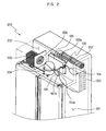
- FIG. 2 is a perspective view showing an upper portion of the refrigerator 200 to which the integrated-type suction pipe module of FIG. 1 is applied.
- the cooling compartment 201 is defined in the refrigerator 200.
- the machine room 202 is defined at a front of the upper portion of the refrigerator 200 to be opened to the atmosphere.
- the evaporator 203 is installed at a rear portion of an upper portion of the cooling compartment 201.
- the compressor 204 is installed at a predetermined position of the machine room 202.
- the integrated-type suction pipe module 100 of FIG. 1 is mounted to a rear surface of the machine room 202, which is in back of the compressor 204.
- the condenser 205 is installed at a left side of the machine room 202.
- a fan 206 is provided between the condenser 205 and the compressor 204 to blow external air to the condenser 205 and the compressor 204.
- the capillary tube 104 connects the condenser 205 to the evaporator 203.
- a part of the capillary tube 104 extending from the condenser 205 meets the first exposed part 101a of the suction pipe 101 which extends from the evaporator 203. Thereafter, the capillary tube 104 extends in parallel to the suction pipe 101 in the foam body 102. Further, a part of the capillary tube 104 which is connected to the evaporator 203, comes out of the foam body 102 together with the second exposed part 101c of the suction pipe 101 which is connected to the compressor 204.
- the refrigerant which flows from the condenser 205 through the capillary tube 104 to the evaporator 203 dissipates heat to the suction pipe 101 while flowing through the part of the capillary tube 104 which extends in the foam body 102 together with the embedded part 101b of the suction pipe 101. Therefore, the temperature of the refrigerant flowing in the capillary tube 104 is reduced. Meanwhile, the refrigerant flowing through the suction pipe 101 absorbs heat from the capillary tube 104 while flowing from the first exposed part 101a of the suction pipe 101 extending from the evaporator 203 to the second exposed part 101c extending to the compressor 204.
- the reference numeral 207 of FIG. 2 denotes an evaporator fan which functions to circulate the air of the cooling compartment 201 through the evaporator 203.
- the machine room 202 is defined in the upper portion of the refrigerator. However, the machine room may be defined in a lower portion of the refrigerator without being limited to the embodiment of FIG. 2.
- preferred embodiments of the present invention provide an integrated-type suction pipe module for refrigerators, which enhances work efficiency while producing a refrigerator and simplifies a structure of a machine room to provide a good appearance. Further, a suction pipe is completely isolated from the atmosphere, thus preventing dew from being formed on the suction pipe.
- the integrated-type suction pipe module of the present invention prevents heat from being transferred between the suction pipe and an interior of a refrigerator, or between the suction pipe and the atmosphere, thus maximizing a heat exchanging effect between a capillary tube and the suction pipe, therefore increasing an operational efficiency of the refrigerator.
Landscapes
- Engineering & Computer Science (AREA)
- Chemical & Material Sciences (AREA)
- Combustion & Propulsion (AREA)
- Physics & Mathematics (AREA)
- Mechanical Engineering (AREA)
- Thermal Sciences (AREA)
- General Engineering & Computer Science (AREA)
- Devices That Are Associated With Refrigeration Equipment (AREA)
- Removal Of Water From Condensation And Defrosting (AREA)
- Cooling Or The Like Of Electrical Apparatus (AREA)
Abstract
Description
According to the present invention in a second aspect, there is provided a refrigerator, comprising: a cooling compartment; a machine room thermally insulated from the cooling compartment, and opened to an atmosphere; an evaporator installed at a predetermined position in the cooling compartment; a compressor installed at a predetermined position in the machine room; and an integrated-type suction pipe module mounted to a predetermined portion of the machine room, and comprising: a suction pipe, comprising; an exposed part placed in the machine room; and an embedded part which is placed to be isolated from the atmosphere; and a foam body in which the embedded part is disposed.
Claims (12)
- An integrated-type suction pipe module (100) for refrigerators, comprising:a suction pipe (101) to define a refrigerant path between an evaporator (203) and a compressor (204), and comprising:an exposed part (101a,101c) placed in a machine room (202) which is exposed to an atmosphere; andan embedded part (101b) which is placed to be isolated from the atmosphere; anda foam body (102) in which the embedded part (101b) is disposed.
- The integrated-type suction pipe module (100) for refrigerators according to claim 1, further comprising a cover (103) to cover the foam body (102) in which the embedded part (101b) is disposed.
- The integrated-type suction pipe module for refrigerators according to claim 2, further comprising a locking part (103) provided at a predetermined portion of the cover (103) to mount the cover (103) to a cabinet of a refrigerator (200).
- The integrated-type suction pipe module (100) for refrigerators according to any preceding claim, further comprising a tube (105) to cover a part of the exposed part (101a,101c) of the suction pipe (101), which is connected to the evaporator (203).
- The integrated-type suction pipe module (100) for refrigerators according to claim 4, wherein the tube (105) is disposed, at an end thereof, in the foam body (102).
- The integrated-type suction pipe module (100) for refrigerators according to claim 1, further comprising a capillary tube (104) arranged in parallel to the suction pipe (101).
- A refrigerator (200), comprising:a cooling compartment (201);a machine room (202) thermally insulated from the cooling compartment (201), and opened to an atmosphere;an evaporator (203) installed at a predetermined position in the cooling compartment (201);a compressor (204) installed at a predetermined position in the machine room (202); andan integrated-type suction pipe module (100) mounted to a predetermined portion of the machine room (202), and comprising:a suction pipe (161), comprising;an exposed part (101a,101c) placed in the machine room (202); andan embedded part (101b) which is placed to be isolated from the atmosphere; anda foam body (102) in which the embedded part (101b) is disposed.
- The refrigerator (200) according to claim 7, wherein the integrated-type suction pipe module (100) further comprises a cover (103) to cover the foam body (102) in which the embedded part (101b) is disposed.
- The refrigerator (200) according to claim 8, further comprising a locking part (103) provided at a predetermined portion of the cover (103) to mount the cover to a predetermined portion of the machine room (202) .
- The refrigerator (200) according to any one of claims 7-9, wherein the integrated-type suction pipe module (100) further comprises a tube (105) to cover a part of the exposed part (101a,101c) of the suction pipe (101), which is connected to the evaporator (203).
- The refrigerator according to claim 10, wherein the tube (105) is disposed, at an end thereof, in the foam body (102).
- The refrigerator according to any one of claims 7-11, wherein the integrated-type suction pipe module (100) further comprises a capillary tube (104) arranged in parallel to the suction pipe (101).
Applications Claiming Priority (2)
| Application Number | Priority Date | Filing Date | Title |
|---|---|---|---|
| KR10-2003-0004865A KR100523035B1 (en) | 2003-01-24 | 2003-01-24 | All-in-one suction pipe set for refrigerator and Refrigerator |
| KR2003004865 | 2003-01-24 |
Publications (2)
| Publication Number | Publication Date |
|---|---|
| EP1441187A2 true EP1441187A2 (en) | 2004-07-28 |
| EP1441187A3 EP1441187A3 (en) | 2006-11-08 |
Family
ID=32588999
Family Applications (1)
| Application Number | Title | Priority Date | Filing Date |
|---|---|---|---|
| EP03256771A Withdrawn EP1441187A3 (en) | 2003-01-24 | 2003-10-27 | Integrated-type suction pipe module and refrigerator having the same |
Country Status (4)
| Country | Link |
|---|---|
| US (1) | US7040118B2 (en) |
| EP (1) | EP1441187A3 (en) |
| KR (1) | KR100523035B1 (en) |
| CN (1) | CN1240977C (en) |
Cited By (6)
| Publication number | Priority date | Publication date | Assignee | Title |
|---|---|---|---|---|
| EP2333459A3 (en) * | 2009-11-30 | 2011-09-21 | Sanyo Electric Co., Ltd. | Refrigerating apparatus |
| WO2012130584A3 (en) * | 2011-03-28 | 2012-11-22 | BSH Bosch und Siemens Hausgeräte GmbH | Refrigerator |
| WO2016192989A1 (en) * | 2015-06-02 | 2016-12-08 | BSH Hausgeräte GmbH | Refrigerant circuit |
| US10228169B2 (en) | 2011-11-04 | 2019-03-12 | Lg Electronics Inc. | Refrigerator with vacuum insulation housing a heat interchanger |
| CN111971516A (en) * | 2018-06-27 | 2020-11-20 | Lg电子株式会社 | Vacuum insulation body and refrigerator |
| WO2022161841A1 (en) * | 2021-02-01 | 2022-08-04 | BSH Hausgeräte GmbH | Refrigeration appliance |
Families Citing this family (49)
| Publication number | Priority date | Publication date | Assignee | Title |
|---|---|---|---|---|
| US7185509B2 (en) * | 2002-08-31 | 2007-03-06 | Samsung Electronics Co., Ltd. | Refrigerator |
| US20040041503A1 (en) * | 2002-08-31 | 2004-03-04 | Samsung Electronics Co., Ltd. | Frame of a wall-embedded refrigerator |
| EP1394488B1 (en) * | 2002-08-31 | 2008-09-17 | Samsung Electronics Co., Ltd. | Cabinet for recessed refrigerators and method for its assembly |
| US7188490B2 (en) | 2003-01-17 | 2007-03-13 | Samsung Electronics Co., Ltd. | Refrigerator |
| KR20090121753A (en) * | 2008-05-23 | 2009-11-26 | 주식회사 한국번디 | Suction Pipe Assembly and Manufacturing Method |
| KR101565387B1 (en) * | 2008-12-10 | 2015-11-03 | 엘지전자 주식회사 | Refrigerator |
| KR101578002B1 (en) * | 2008-12-10 | 2015-12-16 | 엘지전자 주식회사 | Refrigerator |
| KR101578003B1 (en) * | 2009-01-21 | 2015-12-16 | 엘지전자 주식회사 | Refrigerator |
| KR101559787B1 (en) * | 2009-01-21 | 2015-10-13 | 엘지전자 주식회사 | Refrigerator |
| KR101520704B1 (en) * | 2009-01-21 | 2015-05-15 | 엘지전자 주식회사 | Refrigerator |
| KR101559786B1 (en) * | 2009-01-21 | 2015-10-13 | 엘지전자 주식회사 | Refrigerator |
| KR101559788B1 (en) * | 2009-01-30 | 2015-10-13 | 엘지전자 주식회사 | A refrigerator |
| KR101565404B1 (en) * | 2009-01-30 | 2015-11-03 | 엘지전자 주식회사 | A refrigerator |
| US9221210B2 (en) | 2012-04-11 | 2015-12-29 | Whirlpool Corporation | Method to create vacuum insulated cabinets for refrigerators |
| US9140481B2 (en) | 2012-04-02 | 2015-09-22 | Whirlpool Corporation | Folded vacuum insulated structure |
| US10052819B2 (en) | 2014-02-24 | 2018-08-21 | Whirlpool Corporation | Vacuum packaged 3D vacuum insulated door structure and method therefor using a tooling fixture |
| JP5990731B2 (en) * | 2014-09-18 | 2016-09-14 | 東芝ライフスタイル株式会社 | refrigerator |
| US9476633B2 (en) | 2015-03-02 | 2016-10-25 | Whirlpool Corporation | 3D vacuum panel and a folding approach to create the 3D vacuum panel from a 2D vacuum panel of non-uniform thickness |
| US10161669B2 (en) | 2015-03-05 | 2018-12-25 | Whirlpool Corporation | Attachment arrangement for vacuum insulated door |
| US9897370B2 (en) | 2015-03-11 | 2018-02-20 | Whirlpool Corporation | Self-contained pantry box system for insertion into an appliance |
| US9441779B1 (en) * | 2015-07-01 | 2016-09-13 | Whirlpool Corporation | Split hybrid insulation structure for an appliance |
| US10429125B2 (en) | 2015-12-08 | 2019-10-01 | Whirlpool Corporation | Insulation structure for an appliance having a uniformly mixed multi-component insulation material, and a method for even distribution of material combinations therein |
| US10222116B2 (en) | 2015-12-08 | 2019-03-05 | Whirlpool Corporation | Method and apparatus for forming a vacuum insulated structure for an appliance having a pressing mechanism incorporated within an insulation delivery system |
| US12508751B2 (en) | 2015-12-08 | 2025-12-30 | Whirlpool Corporation | Insulation compaction device and method for forming an insulated structure for an appliance |
| US11052579B2 (en) | 2015-12-08 | 2021-07-06 | Whirlpool Corporation | Method for preparing a densified insulation material for use in appliance insulated structure |
| US10041724B2 (en) | 2015-12-08 | 2018-08-07 | Whirlpool Corporation | Methods for dispensing and compacting insulation materials into a vacuum sealed structure |
| US10422573B2 (en) | 2015-12-08 | 2019-09-24 | Whirlpool Corporation | Insulation structure for an appliance having a uniformly mixed multi-component insulation material, and a method for even distribution of material combinations therein |
| US10808987B2 (en) | 2015-12-09 | 2020-10-20 | Whirlpool Corporation | Vacuum insulation structures with multiple insulators |
| US11994336B2 (en) | 2015-12-09 | 2024-05-28 | Whirlpool Corporation | Vacuum insulated structure with thermal bridge breaker with heat loop |
| US10422569B2 (en) | 2015-12-21 | 2019-09-24 | Whirlpool Corporation | Vacuum insulated door construction |
| US10018406B2 (en) | 2015-12-28 | 2018-07-10 | Whirlpool Corporation | Multi-layer gas barrier materials for vacuum insulated structure |
| US10610985B2 (en) | 2015-12-28 | 2020-04-07 | Whirlpool Corporation | Multilayer barrier materials with PVD or plasma coating for vacuum insulated structure |
| US10807298B2 (en) | 2015-12-29 | 2020-10-20 | Whirlpool Corporation | Molded gas barrier parts for vacuum insulated structure |
| US11247369B2 (en) | 2015-12-30 | 2022-02-15 | Whirlpool Corporation | Method of fabricating 3D vacuum insulated refrigerator structure having core material |
| EP3443284B1 (en) | 2016-04-15 | 2020-11-18 | Whirlpool Corporation | Vacuum insulated refrigerator structure with three dimensional characteristics |
| US10712080B2 (en) | 2016-04-15 | 2020-07-14 | Whirlpool Corporation | Vacuum insulated refrigerator cabinet |
| US11320193B2 (en) | 2016-07-26 | 2022-05-03 | Whirlpool Corporation | Vacuum insulated structure trim breaker |
| WO2018034665A1 (en) | 2016-08-18 | 2018-02-22 | Whirlpool Corporation | Machine compartment for a vacuum insulated structure |
| US10352613B2 (en) | 2016-12-05 | 2019-07-16 | Whirlpool Corporation | Pigmented monolayer liner for appliances and methods of making the same |
| DE102017211184A1 (en) * | 2017-06-30 | 2019-01-03 | BSH Hausgeräte GmbH | Domestic refrigeration appliance with a specific module arranged on a Schäumtraverse function module and method for mounting a functional module |
| KR101962146B1 (en) * | 2018-05-21 | 2019-03-26 | 엘지전자 주식회사 | A refrigerator comprising a vacuum space |
| US10907888B2 (en) | 2018-06-25 | 2021-02-02 | Whirlpool Corporation | Hybrid pigmented hot stitched color liner system |
| US10907891B2 (en) | 2019-02-18 | 2021-02-02 | Whirlpool Corporation | Trim breaker for a structural cabinet that incorporates a structural glass contact surface |
| KR102082314B1 (en) * | 2019-03-12 | 2020-02-27 | 엘지전자 주식회사 | A refrigerator comprising a vacuum space |
| KR102622740B1 (en) * | 2019-03-25 | 2024-01-10 | 삼성전자주식회사 | Refrigerator |
| KR102182071B1 (en) * | 2020-01-31 | 2020-11-23 | 엘지전자 주식회사 | A refrigerator comprising a vacuum space |
| KR102332599B1 (en) * | 2020-01-31 | 2021-12-01 | 엘지전자 주식회사 | A refrigerator comprising a vacuum space |
| US12070924B2 (en) | 2020-07-27 | 2024-08-27 | Whirlpool Corporation | Appliance liner having natural fibers |
| KR102491917B1 (en) * | 2020-11-17 | 2023-01-27 | 엘지전자 주식회사 | A refrigerator comprising a vacuum space |
Family Cites Families (7)
| Publication number | Priority date | Publication date | Assignee | Title |
|---|---|---|---|---|
| US1800255A (en) * | 1927-12-30 | 1931-04-14 | Frigidaire Corp | Refrigerating apparatus |
| DE1601858B2 (en) * | 1968-03-13 | 1976-09-09 | Cube, Hans-Ludwig Von, Dipl.-Ing. Dr., 6520 Worms | CASCADE COOLING MACHINE WITH CAPILLARY TUBE CONTROL |
| JPS54145049A (en) * | 1978-05-02 | 1979-11-12 | Toshiba Corp | Refrigerat0r |
| WO1993001459A1 (en) * | 1991-07-05 | 1993-01-21 | Maskinfabrikken Derby A/S | Heat pumping system with flow restricting tube in inner cavity of suction conduit |
| JPH10160324A (en) * | 1996-11-28 | 1998-06-19 | Hitachi Ltd | refrigerator |
| JPH11304338A (en) * | 1998-04-24 | 1999-11-05 | Hitachi Ltd | refrigerator |
| US6401485B1 (en) * | 2000-10-06 | 2002-06-11 | American Standard Inc. | Discharge refrigerant heater for inactive compressor line |
-
2003
- 2003-01-24 KR KR10-2003-0004865A patent/KR100523035B1/en not_active Expired - Fee Related
- 2003-10-27 EP EP03256771A patent/EP1441187A3/en not_active Withdrawn
- 2003-10-28 CN CNB200310104399XA patent/CN1240977C/en not_active Expired - Fee Related
- 2003-12-08 US US10/728,891 patent/US7040118B2/en not_active Expired - Fee Related
Cited By (15)
| Publication number | Priority date | Publication date | Assignee | Title |
|---|---|---|---|---|
| EP2333459A3 (en) * | 2009-11-30 | 2011-09-21 | Sanyo Electric Co., Ltd. | Refrigerating apparatus |
| WO2012130584A3 (en) * | 2011-03-28 | 2012-11-22 | BSH Bosch und Siemens Hausgeräte GmbH | Refrigerator |
| US11698211B2 (en) | 2011-11-04 | 2023-07-11 | Lg Electronics Inc. | Refrigerator with vacuum insulation housing a heat interchanger |
| US10228169B2 (en) | 2011-11-04 | 2019-03-12 | Lg Electronics Inc. | Refrigerator with vacuum insulation housing a heat interchanger |
| EP2589905A3 (en) * | 2011-11-04 | 2019-09-04 | LG Electronics | Refrigerator |
| EP4325141A3 (en) * | 2011-11-04 | 2024-08-07 | LG Electronics Inc. | Refrigerator |
| US12313309B2 (en) | 2011-11-04 | 2025-05-27 | Lg Electronics Inc. | Refrigerator with vacuum insulation housing a heat interchanger |
| WO2016192989A1 (en) * | 2015-06-02 | 2016-12-08 | BSH Hausgeräte GmbH | Refrigerant circuit |
| CN111971516A (en) * | 2018-06-27 | 2020-11-20 | Lg电子株式会社 | Vacuum insulation body and refrigerator |
| EP3814701A4 (en) * | 2018-06-27 | 2022-03-23 | LG Electronics Inc. | VACUUM ADIABATIC BODY AND REFRIGERATOR |
| US11428456B2 (en) | 2018-06-27 | 2022-08-30 | Lg Electronics Inc. | Vacuum adiabatic body and refrigerator |
| US11913706B2 (en) | 2018-06-27 | 2024-02-27 | Lg Electronics Inc. | Vacuum adiabatic body and refrigerator |
| US12253296B2 (en) | 2018-06-27 | 2025-03-18 | Lg Electronics Inc. | Vacuum adiabatic body and refrigerator |
| EP4653745A3 (en) * | 2018-06-27 | 2026-02-25 | LG Electronics Inc. | Vacuum adiabatic body and refrigerator |
| WO2022161841A1 (en) * | 2021-02-01 | 2022-08-04 | BSH Hausgeräte GmbH | Refrigeration appliance |
Also Published As
| Publication number | Publication date |
|---|---|
| US20040144130A1 (en) | 2004-07-29 |
| EP1441187A3 (en) | 2006-11-08 |
| KR100523035B1 (en) | 2005-10-24 |
| CN1517638A (en) | 2004-08-04 |
| KR20040067648A (en) | 2004-07-30 |
| US7040118B2 (en) | 2006-05-09 |
| CN1240977C (en) | 2006-02-08 |
Similar Documents
| Publication | Publication Date | Title |
|---|---|---|
| EP1441187A2 (en) | Integrated-type suction pipe module and refrigerator having the same | |
| US20100242525A1 (en) | Refrigerator | |
| US7216506B2 (en) | Refrigerator | |
| KR102366751B1 (en) | Air conditioner and control method thereof | |
| EP3593070B1 (en) | Refrigerator | |
| US7003973B2 (en) | Refrigerator and cooling system therefor | |
| US20070044491A1 (en) | Vehicle air conditioning system | |
| JP2008169812A (en) | Sound insulation sheet | |
| JPH07146054A (en) | refrigerator | |
| JP2013257115A (en) | Refrigerator-freezer | |
| US20060037356A1 (en) | Refrigerator | |
| KR100540436B1 (en) | Machine room heat dissipation structure of the refrigerator | |
| JP2001099541A (en) | Refrigerator | |
| EP1604159B1 (en) | Refrigerator with noise reduction system | |
| JP2007145104A (en) | Vehicular air-conditioner | |
| KR100484661B1 (en) | Refrigerator increased with inner space | |
| JP4252340B2 (en) | refrigerator | |
| JP2004219031A (en) | Air conditioner | |
| GB2154722A (en) | Refrigerator | |
| KR200288354Y1 (en) | Combination structure for outside fan and inside adiabatic of a air conditioner | |
| KR200249922Y1 (en) | Built-in type grocery refrigerator | |
| KR100363314B1 (en) | Heat exchanger with second time heat exchange function | |
| JP2007078282A (en) | Refrigerator | |
| KR200214197Y1 (en) | Noise blocking structure of air conditioner outdoor heat exchanger | |
| KR20080025965A (en) | Air conditioner |
Legal Events
| Date | Code | Title | Description |
|---|---|---|---|
| PUAI | Public reference made under article 153(3) epc to a published international application that has entered the european phase |
Free format text: ORIGINAL CODE: 0009012 |
|
| AK | Designated contracting states |
Kind code of ref document: A2 Designated state(s): AT BE BG CH CY CZ DE DK EE ES FI FR GB GR HU IE IT LI LU MC NL PT RO SE SI SK TR |
|
| AX | Request for extension of the european patent |
Extension state: AL LT LV MK |
|
| PUAL | Search report despatched |
Free format text: ORIGINAL CODE: 0009013 |
|
| AK | Designated contracting states |
Kind code of ref document: A3 Designated state(s): AT BE BG CH CY CZ DE DK EE ES FI FR GB GR HU IE IT LI LU MC NL PT RO SE SI SK TR |
|
| AX | Request for extension of the european patent |
Extension state: AL LT LV MK |
|
| 17P | Request for examination filed |
Effective date: 20070328 |
|
| AKX | Designation fees paid |
Designated state(s): DE FR GB |
|
| STAA | Information on the status of an ep patent application or granted ep patent |
Free format text: STATUS: THE APPLICATION HAS BEEN WITHDRAWN |
|
| 18W | Application withdrawn |
Effective date: 20090908 |