EP1440947A1 - Optical fibre and its preform and method of their manufacture starting from a glass tube - Google Patents
Optical fibre and its preform and method of their manufacture starting from a glass tube Download PDFInfo
- Publication number
- EP1440947A1 EP1440947A1 EP04000610A EP04000610A EP1440947A1 EP 1440947 A1 EP1440947 A1 EP 1440947A1 EP 04000610 A EP04000610 A EP 04000610A EP 04000610 A EP04000610 A EP 04000610A EP 1440947 A1 EP1440947 A1 EP 1440947A1
- Authority
- EP
- European Patent Office
- Prior art keywords
- glass pipe
- glass
- optical fiber
- pipe
- fiber preform
- Prior art date
- Legal status (The legal status is an assumption and is not a legal conclusion. Google has not performed a legal analysis and makes no representation as to the accuracy of the status listed.)
- Granted
Links
Images








Classifications
-
- C—CHEMISTRY; METALLURGY
- C03—GLASS; MINERAL OR SLAG WOOL
- C03B—MANUFACTURE, SHAPING, OR SUPPLEMENTARY PROCESSES
- C03B37/00—Manufacture or treatment of flakes, fibres, or filaments from softened glass, minerals, or slags
- C03B37/01—Manufacture of glass fibres or filaments
- C03B37/012—Manufacture of preforms for drawing fibres or filaments
-
- C—CHEMISTRY; METALLURGY
- C03—GLASS; MINERAL OR SLAG WOOL
- C03C—CHEMICAL COMPOSITION OF GLASSES, GLAZES OR VITREOUS ENAMELS; SURFACE TREATMENT OF GLASS; SURFACE TREATMENT OF FIBRES OR FILAMENTS MADE FROM GLASS, MINERALS OR SLAGS; JOINING GLASS TO GLASS OR OTHER MATERIALS
- C03C13/00—Fibre or filament compositions
-
- C—CHEMISTRY; METALLURGY
- C03—GLASS; MINERAL OR SLAG WOOL
- C03B—MANUFACTURE, SHAPING, OR SUPPLEMENTARY PROCESSES
- C03B37/00—Manufacture or treatment of flakes, fibres, or filaments from softened glass, minerals, or slags
- C03B37/01—Manufacture of glass fibres or filaments
- C03B37/012—Manufacture of preforms for drawing fibres or filaments
- C03B37/01205—Manufacture of preforms for drawing fibres or filaments starting from tubes, rods, fibres or filaments
- C03B37/01211—Manufacture of preforms for drawing fibres or filaments starting from tubes, rods, fibres or filaments by inserting one or more rods or tubes into a tube
-
- C—CHEMISTRY; METALLURGY
- C03—GLASS; MINERAL OR SLAG WOOL
- C03B—MANUFACTURE, SHAPING, OR SUPPLEMENTARY PROCESSES
- C03B37/00—Manufacture or treatment of flakes, fibres, or filaments from softened glass, minerals, or slags
- C03B37/01—Manufacture of glass fibres or filaments
- C03B37/012—Manufacture of preforms for drawing fibres or filaments
- C03B37/01205—Manufacture of preforms for drawing fibres or filaments starting from tubes, rods, fibres or filaments
- C03B37/01225—Means for changing or stabilising the shape, e.g. diameter, of tubes or rods in general, e.g. collapsing
- C03B37/01228—Removal of preform material
-
- C—CHEMISTRY; METALLURGY
- C03—GLASS; MINERAL OR SLAG WOOL
- C03B—MANUFACTURE, SHAPING, OR SUPPLEMENTARY PROCESSES
- C03B37/00—Manufacture or treatment of flakes, fibres, or filaments from softened glass, minerals, or slags
- C03B37/01—Manufacture of glass fibres or filaments
- C03B37/012—Manufacture of preforms for drawing fibres or filaments
- C03B37/01205—Manufacture of preforms for drawing fibres or filaments starting from tubes, rods, fibres or filaments
- C03B37/01225—Means for changing or stabilising the shape, e.g. diameter, of tubes or rods in general, e.g. collapsing
- C03B37/01248—Means for changing or stabilising the shape, e.g. diameter, of tubes or rods in general, e.g. collapsing by collapsing without drawing
-
- C—CHEMISTRY; METALLURGY
- C03—GLASS; MINERAL OR SLAG WOOL
- C03C—CHEMICAL COMPOSITION OF GLASSES, GLAZES OR VITREOUS ENAMELS; SURFACE TREATMENT OF GLASS; SURFACE TREATMENT OF FIBRES OR FILAMENTS MADE FROM GLASS, MINERALS OR SLAGS; JOINING GLASS TO GLASS OR OTHER MATERIALS
- C03C13/00—Fibre or filament compositions
- C03C13/04—Fibre optics, e.g. core and clad fibre compositions
-
- C—CHEMISTRY; METALLURGY
- C03—GLASS; MINERAL OR SLAG WOOL
- C03B—MANUFACTURE, SHAPING, OR SUPPLEMENTARY PROCESSES
- C03B2201/00—Type of glass produced
- C03B2201/06—Doped silica-based glasses
- C03B2201/07—Impurity concentration specified
- C03B2201/075—Hydroxyl ion (OH)
-
- C—CHEMISTRY; METALLURGY
- C03—GLASS; MINERAL OR SLAG WOOL
- C03B—MANUFACTURE, SHAPING, OR SUPPLEMENTARY PROCESSES
- C03B2201/00—Type of glass produced
- C03B2201/06—Doped silica-based glasses
- C03B2201/08—Doped silica-based glasses doped with boron or fluorine or other refractive index decreasing dopant
- C03B2201/12—Doped silica-based glasses doped with boron or fluorine or other refractive index decreasing dopant doped with fluorine
-
- C—CHEMISTRY; METALLURGY
- C03—GLASS; MINERAL OR SLAG WOOL
- C03B—MANUFACTURE, SHAPING, OR SUPPLEMENTARY PROCESSES
- C03B2201/00—Type of glass produced
- C03B2201/06—Doped silica-based glasses
- C03B2201/20—Doped silica-based glasses doped with non-metals other than boron or fluorine
-
- C—CHEMISTRY; METALLURGY
- C03—GLASS; MINERAL OR SLAG WOOL
- C03B—MANUFACTURE, SHAPING, OR SUPPLEMENTARY PROCESSES
- C03B2201/00—Type of glass produced
- C03B2201/06—Doped silica-based glasses
- C03B2201/30—Doped silica-based glasses doped with metals, e.g. Ga, Sn, Sb, Pb or Bi
- C03B2201/31—Doped silica-based glasses doped with metals, e.g. Ga, Sn, Sb, Pb or Bi doped with germanium
Definitions
- the present invention relates to a method of producing an optical fiber preform with the collapsing process and to an optical fiber preform and an optical fiber produced with the method.
- the collapsing process is a process to produce an optical fiber preform by collapsing a glass pipe to form a solid body.
- the collapsing operation may be performed with a glass rod inserted into a glass pipe.
- the glass pipe and the glass rod are unified.
- Figure 17 is a schematic diagram showing the collapsing process.
- a glass rod 2 is inserted in a glass pipe 1.
- the glass pipe 1 is held by holding portions 4 of a glass-processing lathe 13. While the glass pipe 1 is rotated together with the glass rod 2, one end of the glass pipe is sealed by heating it with a heat source 3. Then, the heat source 3 is moved to collapse the glass pipe by heating it.
- Figure 18 is a graph showing an increment in transmission loss at a 1.4 ⁇ m wavelength band due to OH groups.
- OH groups in silica glass have a high absorption peak (OH absorption) in the vicinity of 1.4 ⁇ m in wavelength.
- the OH absorption increases the transmission loss at a 1.4- ⁇ m band (OH-originated loss) and makes it difficult to transmit signals in the 1.4- ⁇ m hand and excitation light for Raman amplification. Therefore, it is desirable to minimize the OH absorption.
- an optical fiber preform is produced with the collapsing process, it has been difficult to reduce the OH absorption.
- An object of the present invention is to offer a method of producing with the collapsing process an optical fiber preform capable of forming an optical fiber in which an increment in transmission loss due to the OH absorption is reduced and to offer an optical fiber preform and an optical fiber produced with the method.
- the foregoing object is attained by offering the following method of producing an optical fiber preform.
- the method comprises:
- the present invention offers the following method of producing an optical fiber preform.
- the method comprises:
- the present invention offers an optical fiber preform produced through the following steps:
- the present invention offers an optical fiber produced by drawing an optical fiber preform produced through the following steps:
- the optical fiber preform may be a glass body from which an optical fiber can be formed by directly drawing the glass body.
- the optical fiber preform may also be a glass body (an intermediate of an optical fiber preform) to be further processed for the subsequent drawing.
- a silica-glass body having on its surface adsorbed hydrogen atom-containing substances, such as hydrogen atom (H), hydrogen molecules (H 2 ), water (H 2 O), methanol (CH 3 OH), methane (CH 4 ), and ketone (CH 3 COCH 3 ).
- hydrogen atom-containing substances such as hydrogen atom (H), hydrogen molecules (H 2 ), water (H 2 O), methanol (CH 3 OH), methane (CH 4 ), and ketone (CH 3 COCH 3 ).
- the hydrogen atom-containing substance is H 2 O
- a heating treatment causes the H 2 O to be chemically adsorbed onto the surface of the glass.
- the heating treatment is performed at a temperature over 550 °C
- the activation energy of the adsorption becomes twice as high as that produced at low temperatures, making it difficult to remove the H 2 O from the surface of the glass.
- the H 2 O reacts with the glass at its surface to form an OH group. Even when the heating is performed at a temperature as low as 200 °C or above, the H 2 O may react with the glass.
- the method of producing an optical fiber preform performs the following treatment before a glass pipe is transformed into a solid body by the collapsing process.
- the treatment is performed to reduce the hydrogen atom-containing substances adsorbed on the inner surface of the glass pipe or the hydrogen atom-containing substances contained in the atmosphere in the glass pipe or both.
- drying the treatment that reduces not only H 2 O but also other hydrogen atom-containing substances
- drying step the step that performs the drying.
- the drying treatment eliminates the formation of OH groups even when the glass pipe is heated at high temperatures in the collapsing step.
- the drying treatment enables the production of an optical fiber preform that can reduce the increment in the transmission loss due to the OH absorption in the optical fiber.
- the concentration of the OH groups remaining at the optical fiber preform's portion formed by the interface portion at the time of the collapsing can be reduced to 100 wt. ppb or below.
- the OH-originated loss of the optical fiber can be reduced to less than 0.5 dB/km at a wavelength of 1.38 ⁇ m.
- the drying step is performed at a temperature of 550 °C or below. If the heating temperature exceeds 550 °C, it becomes difficult to remove H 2 O and other substances adsorbed on the silica glass. If the temperature exceeds 600 °C, the H 2 O and other substances react with the glass at its surface to form OH groups.
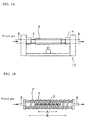
- FIGS. 1A and 1B are schematic diagrams showing the "blowing-away purging," one of the embodiments of the drying step of the present invention.
- Figure 1A shows the diagram when only a glass pipe is treated.
- Figure 1B shows the diagram when a glass rod is inserted in the glass pipe.
- a glass pipe 1 whose both ends are open is held by holding portions 4.
- a dried gas is introduced into the glass pipe 1 from a gas line 5 attached to one end of the glass pipe 1 to perform the blowing-away purging through a gas line 6 attached to the other end of the pipe.
- a dried gas is introduced into the glass pipe 1 from a gas line 5 attached to one end of the pipe 1 to perform the blowing-away purging through a gas line 6 attached to the other end of the pipe.
- the glass pipe When the blowing-away purging is performed, the glass pipe may be heated. It is desirable that the heating be performed with a cylindrical mantle heater 7, a tape heater 7' wound on the outer surface of the glass pipe 1, or an electric furnace to facilitate the temperature control.
- the heating may be performed with another means such as an oxyhydrogen burner or a plasma burner. It is possible to perform the blowing-away purging for a prolonged period without heating.
- the blowing of a dried gas from one end to the other can not only desorb hydrogen atom-containing substances adsorbed on the inner surface of the glass pipe 1 and on the surface of the glass rod 2 but also reduce the amount of the hydrogen atom-containing substances in the atmosphere in the glass pipe 1. In addition, this process reduces the amount of the re-adsorption of the desorbed hydrogen atom-containing substances onto the surface of the glass.
- the types of dried gas for the purging in the drying step include an inert gas, such as nitrogen (N 2 ), helium (He), or argon (Ar), a reactive gas, such as chlorine (Cl 2 ) or thionyl chloride (SOCl 2 ), and an oxygen gas (O 2 ). It is desirable that the dried gas contains hydrogen atom-containing substances at a concentration of 10 vol. ppm or less in total, more desirably 1 vol. ppm or less.
- the volume of the gas blown per minute is at least 10 times the inner volume of the glass pipe in the longitudinal range heated in the drawing step.
- the sufficient volume of the gas reduces a back diffusion of the hydrogen atom-containing substances from the downstream.
- blowing-away purging be carried out for at least one hour in the drying step.
- the long-time purging can sufficiently reduce the amount of the adsorbed hydrogen atom-containing substances.
- FIG 11 is a graph showing the amount of the water desorbing from a heated silica-glass body.
- H 2 O whose desorption can be promoted at 60 °C or higher (peak I) because it is weakly bonded to the surface of the glass and the other is the H 2 O whose desorption can be promoted at 400 °C or higher (peak II) because it is strongly bonded to the surface of the glass.
- peak I the H 2 O whose desorption can be promoted at 60 °C or higher
- peak II peak II
- the blowing-away purging is performed at a temperature lower than 200 °C, the formation of OH groups can be suppressed. If the temperature is 200 °C or higher, H 2 O may react with the glass at its surface.
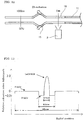
- range A shows the range corresponding to the effective portion of the optical fiber preform to be formed by the collapsing operation (the effective portion is the portion of the optical fiber preform to be used as the final product).
- Range A is heated at 550 °C or higher in the collapsing step.
- Range B shows the range to be heated in the drying step.
- range B is wider than range A. This arrangement can prevent OH groups contained in the glass pipe in range B from leaving the glass pipe to form H 2 O and then being re-adsorbed onto the inner surface of the glass pipe in range A.
- Embodiment (B), expressed as the "evacuation,” is explained below.
- H 2 O has a saturated vapor pressure of 4 kPa at a temperature of 25 °C. Therefore, when the internal pressure of the glass pipe is reduced to a value lower than this value, the desorption of the H 2 O can be promoted. Furthermore, the reduction in the internal pressure can increase the mean free path for the H 2 O and therefore reduce the possibility of its collision onto the wall of the glass. As a result, the re-adsorption of the H 2 O onto the surface of the glass can be significantly suppressed.
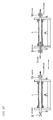
- FIGS 2A to 2D are schematic diagrams showing the "cyclic purging," one of the embodiments of the drying step of the present invention.
- Figures 2A to 2C show the diagrams when the glass pipe has a through hollow.
- Figure 2D shows the diagram when the glass pipe is sealed at some midpoint.
- the cyclic purging is carried out by performing at least once the following procedure from (a) to (c), for example:
- a gas line 8 which is connected to a vacuum pump, is connected to a gas line 5 attached to the end of the glass pipe for introducing a gas.
- a valve 9 is closed and a valve 13 is opened to evacuate the glass pipe 11 through the gas lines 5 and 8. This evacuation reduces the internal pressure of the glass pipe 11 to an absolute pressure of 4 kPa or below, for example, to evaporate adsorbed water and other substances.
- valve 9 is opened to introduce a dried gas into the glass pipe, and at the same time the valve 13 is closed to raise the internal pressure of the glass pipe to an absolute pressure of 50 kPa or above, for example.
- the evacuation and the gas introduction are conducted alternately at least once, the amount of the hydrogen atom-containing substances adsorbed on the surfaces of the glass pipe and the glass rod can be significantly reduced.
- a holding pipe may be connected to one end or both ends of the glass pipe to perform the collapsing operation of the present invention.
- another step may be introduced to connect a holding pipe to at least one end of the glass pipe.
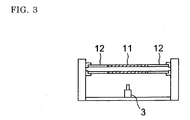
- Figure 3 is a schematic diagram showing the glass pipe having the connected holding pipes.
- a holding pipe 12 is connected to both ends of a glass pipe 11, which is to be used as the effective portion in the optical fiber preform. This method has an advantage in that the use of the costly glass pipe can be reduced to a required minimum.
- the holding pipe When a holding pipe is connected to the glass pipe to perform the collapsing operation of the present invention, it is desirable that the holding pipe have few hydrogen atom-containing substances adsorbed on its inner surface and contain a low concentration of OH groups in its body. More specifically, it is desirable that the holding pipe contain OH groups at a concentration of 10 wt. ppm or less. The reason is that when the holding pipe is heated during the glass-pipe sealing step and the collapsing step, OH groups contained in the holding pipe may leave the holding pipe to form H 2 O and then be re-adsorbed onto the inner surface of the glass pipe in the effective portion.
- FIG. 12 is a schematic diagram showing an embodiment of the holding pipe of the present invention, in which the holding pipe is connected to the glass pipe 11.
- a holding pipe 16 is provided with a radiating portion 15 that has the shape of a knot formed by using the pipe.
- the temperature of the portion of the holding pipe 16 opposite to the heat source 3 with respect to the radiating portion 15 is lower than the temperature when no radiating portion is provided.
- the temperature of the portion of the holding pipe 1,000 mm apart from the heat source 3 was 50 °C when the radiating portion 15 was provided between the portion and the heat source 3 and 100 °C when no radiating portion was provided.
- the portion between the radiating portion 15 and the glass pipe 11 is subjected to the drying step of the present invention to remove hydrogen atom-containing substances.
- the portion of the holding pipe 16 opposite to the glass pipe 11 with respect to the radiating portion 15 is not heated to high temperatures. Consequently, hydrogen atom-containing substances adsorbed in this portion do not diffuse toward the effective portion of the glass pipe 11 during the production process.
- the radiating portion 15 may have a shape other than the shape of a knot formed by using the pipe.
- an opaque silica-glass pipe capable of scattering infrared rays may be inserted into the holding pipe 16 to form the radiating portion 15.
- the fusion-connected portion may be used as the radiating portion 15.
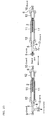
- FIGS 4A to 4C are schematic diagrams showing an embodiment of the connecting step of the present invention.
- the connection between the glass pipe 11 and the holding pipe 12 is performed by heating the two members with a heat source 3 so that they can be fusion-connected.
- a heat source 3 so that they can be fusion-connected.
- a plasma burner, an induction furnace, a resistance furnace, or another heat source that does not produce H 2 O is used, the intrusion of H 2 O can be reduced significantly at the time of the connection between the glass pipe and the holding pipe.
- an oxyhydrogen burner or another heat source that produces H 2 O hydrogen atom-containing substances may intrude into the glass pipe and the holding pipe at the time of the connection between the two members.
- a dried gas is introduced into both pipes from the end opposite to the end to be connected.
- one of the two pipes is provided with a sealing material 14 attached to its end opposite to the end to be connected.
- a dried gas is introduced into the other pipe from its end opposite to the end to be connected.
- Fig. 4C Yet another alternative is shown in Fig. 4C.
- each pipe is provided with a sealing material 14 attached to its end opposite to the end to be connected.
- the dried gas can be the same type of the dried gas as used in the drying step. It is desirable that the dried gas contains hydrogen atom-containing substances at a concentration of 10 vol. ppm or less in total, more desirably 1 vol. ppm or less. It is also desirable to perform the drying step after the connecting step. This is another desirable embodiment.
- the collapsing operation of the present invention include a step in which the inner surface of the glass pipe is gas phase-etched before or after the drying step (this step is called an "etching step")
- this step is called an "etching step”
- glass pipe is used as a generic term that includes a glass pipe having a holding pipe connected to at least one end of it.
- the gas-phase etching has the following effects:
- Figure 5 is a schematic diagram showing an embodiment of the etching step of the present invention.
- the glass pipe 1 is heated with a heat source 3 while an etching gas is introduced into the pipe from one end of it.
- Range A shows the range corresponding to the effective portion of the optical fiber preform.
- Range A is heated at 550 °C or higher in the following step, for example, the collapsing step.
- Range C shows the range to be gas phase-etched. It is desirable that range C include range A.
- the types of gas for the gas-phase etching include sulfur hexafluoride (SF 6 ), fluorocarbon (C 2 F 6 ), and silicon tetrafluoride (SiF 4 ).
- the gas concentration, the etching time, and the heating temperature can be determined according to the intended degree of etching.
- the etching gas may be mixed with Cl 2 .
- a preliminary drying step may be provided to dry the inside of the glass pipe. This step can prevent the formation of a highly acidic liquid due to the reaction between the etching gas and H 2 O.
- H 2 O if H 2 O remains in the pipe, concentrated sulfuric acid is formed. It is difficult to remove the concentrated sulfuric acid. As a result, impurities such as OH groups intrude into the produced optical fiber. Furthermore, the formation of the concentrated sulfuric acid is extremely hazardous to the workers.
- a step may be performed to deposit a glass layer on the inner surface of the glass pipe by using a method such as the modified chemical vapor deposition method (MCVD method) or the plasma-activated chemical vapor deposition method (PCVD method) (this step is called a "glass-depositing step").
- MCVD method modified chemical vapor deposition method
- PCVD method plasma-activated chemical vapor deposition method
- the following gases are introduced into the glass pipe 1 from its one end: (a) a material gas for the glass composed of silicon tetrachloride (SiCl 4 ), (b) a material dopant gas for controlling the refractive index composed of a gas such as germanium tetrachloride (GeCl 4 ), phosphorus oxychloride, SiF 4 , or boron trichloride, (c) an O 2 gas, and (d) an He gas.
- a heat source is provided at the outside of the glass pipe so as to be able to move relatively to the glass pipe. The heating of the glass pipe with the heat source forms a glass layer on the inner surface of the glass pipe.
- the types of the heat source include an oxyhydrogen burner, a plasma flame, and an electric furnace such as an induction furnace or a resistance furnace.
- the inside of the etched glass pipe is almost free of hydrogen atom-containing substances.
- hydrogen atom-containing substances are not adsorbed on the inner surface of the glass pipe. Therefore, the etched glass pipe is eminently suitable as the starting glass pipe for the MCVD or PCVD method.
- the etched glass pipe can eliminate the need for synthesizing the so-called optical cladding layer.
- the etched glass pipe is advantageous in that even when a core layer is deposited directly onto the inner surface of the glass pipe, a high-quality optical fiber can be obtained.
- a step may be performed to insert a glass rod into the glass pipe (this step is called an "assembling step"). More specifically, the above-described steps may be performed in the following order: the etching step, the glass-depositing step, the assembling step, the drying step, the sealing step, and the collapsing step.
- FIG. 8 is a schematic diagram showing an embodiment of the chemically purifying step of the present invention.
- a glass pipe 1 is heated with a heat source 3 at about 1,000 °C while introducing the following gas into it from a gas line 5.
- the gas is a reactive gas such as Cl 2 , SOCl 2 , SiCl 4 , GeCl 4 , or carbon tetrachloride (CCl 4 ).
- This process can transform a metal and a metal oxide having a low vapor pressure into a metal chloride having a high vapor pressure so that they can be removed (for example, nickel chloride has a vapor pressure of 1 atm at 993 °C and iron chloride has a vapor pressure of 1 atm at about 1,020 °C).
- a step may be performed to dry the inside of the glass pipe (this step is called an "additional drying step").
- additional drying step The reason is that Cl 2 used in the chemically purifying step usually contains 1 ppm or so H 2 O and it is desirable to remove the H 2 O.
- FIGS 9A and 9C are schematic diagrams showing an embodiment of the sealing step of the present invention.
- the glass pipe 1 is heated with a heat source 3 placed at the outside of the pipe to seal the glass pipe 1 by fusion at the end portion.
- a valve 10 in a gas line 6 attached to one end of the glass pipe may be closed to seal the glass pipe so that the gas cannot be discharged.
- the cyclic purging is performed through the following procedure: First, the gas in the glass pipe is discharged to reduce the pressure inside the pipe. Second, a dried gas is introduced into the pipe to raise the pressure inside the pipe.
- FIGs 10A and 10B are schematic diagrams showing an embodiment of the collapsing step of the present invention.
- the glass pipe 1 is heated with the moving heat source 3 to collapse it to perform the collapsing step.
- a gas such as Cl 2 , O 2 , a mixed gas of Cl 2 and O 2 , or a mixed gas of Cl 2 , O 2 , and He, may be introduced into the glass pipe 1. It is desirable that the gas contains hydrogen atom-containing substances at a concentration of 10 vol. ppm or less in total. While the gas introduction is maintained, the inside of the glass pipe may be evacuated to reduce the pressure to the range of 100 to 0.1 kPa.
- the inside of the glass pipe may be evacuated without introducing the gas.
- the internal pressure of the glass pipe may be adjusted to become slightly higher than atmospheric pressure. More specifically, it is desirable that the pressure difference between the internal pressure and atmospheric pressure be +0.01 to +4 kPa, more desirably +0.01 to +1 kPa.
- the glass pipe 1 and the glass rod 2 are fusion-unified by collapsing.
- a gas such as Cl 2 , N 2 , or O 2 . This procedure can reduce the concentration of the air intruding into the glass pipe.
- Fig. 10B it is more desirable to provide a gas-introducing port and a gas-discharging port independently at the end of the glass pipe 11.
- One of the desirable embodiments of the present invention comprises the following steps in this order: the connecting step, the preliminary drying step, the etching step, the glass-depositing step or the assembling step or both, the drying step, the chemically purifying step, the sealing step, the cyclic-purging operation, and the collapsing step.
- the glass rod and the glass pipe to be used in the present invention may be produced with the vapor-phase axial deposition method (VAD method), the modified chemical vapor deposition method (MCVD method), the outside vapor deposition method (OVD method), or another well-known method. It is also desirable that the glass rod produced by performing the collapsing operation of the present invention be used as the starting glass rod. Alternatively, the glass rod produced by the present invention may be transformed into a pipe through a hollow-forming processing such as boring. The glass pipe thus produced can be used as the starting glass pipe to be collapsed again by re-performing the present invention. This is another form of the desirable embodiments.
- VAD method vapor-phase axial deposition method
- MCVD method modified chemical vapor deposition method
- OTD method outside vapor deposition method
- a solid glass body produced with the VAD method When a solid glass body produced with the VAD method is processed into a glass pipe, it is desirable to draw the glass body before it is bored, rather than boring it before it is drawn. If the glass body is first bored to form a glass pipe, when the glass pipe is heated at the time of the drawing, the water adsorbed on the inner surface of the glass pipe diffuses into the wall of the glass pipe. The diffused water is difficult to remove. When the glass body is drawn before it is bored, it is desirable to etch the inner surface of the glass pipe in a subsequent step such that the inner-surface portion of the glass pipe is rather deeply (for example, one or two mm) removed.
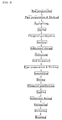
- Figure 6 shows a flow chart for Example 1.
- the optical fiber had the following transmission characteristics at a wavelength of 1,550 nm: a transmission loss of 0.50 dB/km, a chromatic dispersion of -41 ps/km/nm, a dispersion slope of -0.01 ps/km/nm 2 , an A eff of 8.5 ⁇ m 2 , a cutoff wavelength of 1,050 nm, and a PMD of 0.1 ps/km 1/2 . These characteristics proved that the optical fiber was highly non-linear.
- the optical fiber had good properties as an optical fiber for Raman amplification.
- the transmission loss-wavelength property of the optical fiber is shown by a solid line in Fig. 14. As can be seen from Fig. 14, the excessive transmission loss due to the OH group in the 1.4- ⁇ m band (OH-originated loss) is suppressed to less than 0.1 dB/km at a wavelength of 1.38 ⁇ m.
- An optical fiber was produced with the same method as in Example 1 except that the first drying step (step 4)) and the chemically purifying step (step 5)) using Cl 2 were omitted.
- the transmission loss-wavelength property of the optical fiber is shown by a broken line in Fig. 14. As can be seen from Fig. 14, the OH-originated loss was 1.3 dB/km.
- Figure 7 shows a flow chart for Example 2.
- the optical fiber had the following transmission characteristics at a wavelength of 1,550 nm: a transmission loss of 0.49 dB/km, a chromatic dispersion of -159.5 ps/km/nm, a dispersion slope of -0.65 ps/km/nm 2 , an A eff of 17 ⁇ m 2 , a cutoff wavelength of 1,380 nm, and a PMD of about 0.05 ps/km 1/2 .
- the transmission loss-wavelength property of the optical fiber is shown in Fig. 16.
- the excessive transmission loss due to the OH group in the 1.4- ⁇ m band is suppressed to less than 0.05 dB/km at a wavelength of 1.38 ⁇ m.
- the optical fiber is a broad-band dispersion-compensating fiber that can compensate the chromatic dispersion of an optical fiber, having a 1.3- ⁇ m-band zero-dispersion wavelength, from 1.45 to 1.62 ⁇ m. Because the optical fiber is free from the excessive transmission loss due to the OH group, it has a low transmission loss in the vicinity of 1.45 ⁇ m , proving that it has a good transmission property. Furthermore, the optical fiber is suitable for performing Raman amplification.
- the fiber As a test for proving the property of the optical fiber, the fiber was placed in an H 2 atmosphere at a concentration of 100% at a temperature of 80 °C for 24 hours. Then, the transmission loss was measured at 1.38 ⁇ m. The measured result showed that the increment in the loss was as small as below the measuring limit of 0.05 dB/km.
- the increment in the transmission loss due to the OH group was 0.03 dB/km at a wavelength of 1.38 ⁇ m.
- An optical fiber was produced with the same method as in Example 3 except that step 4) (the drying step) was omitted.
- step 4) the drying step
- the increment in the transmission loss due to the OH group was 2.0 dB/km at a wavelength of 1.38 ⁇ m.
- the increment in the transmission loss due to the OH group was 0.02 dB/km at a wavelength of 1.38 ⁇ m.
- the glass body in 1) of Example 4 was not directly heated with an oxyhydrogen flame. This is the reason why the optical fiber in Example 4 had an increment in the transmission loss smaller than that of the optical fiber in Example 3.
- An optical fiber was produced with the same method as in Example 4 except that the drying steps were omitted.
- the increment in the transmission loss due to the OH group was 1.5 dB/km at a wavelength of 1.38 ⁇ m.
- a tape heater or a mantle heater was used as the heat source in the drying step.
- other heat sources such as an induction furnace, a resistance furnace, and a laser may also be used.
- An oxyhydrogen-flame burner or a plasma-flame burner was used in the collapsing step.
- other heat sources such as an induction furnace and a resistance furnace may also be used.
- a vertical apparatus may also be used. When a vertical apparatus whose heat source has an axially symmetrical temperature distribution is used, it is not necessary to rotate the glass pipe and the glass rod.
- the glass pipe and the glass rod may be produced by using any of the well-known methods in this technical field, such as the VAD method, OVD method, MCVD method, and collapsing process.
- the surface purification and the size adjustment of the glass pipe and the glass rod may be performed by chemical etching (gas phase or liquid phase) in place of mechanical grinding.
Landscapes
- Chemical & Material Sciences (AREA)
- Engineering & Computer Science (AREA)
- Materials Engineering (AREA)
- Geochemistry & Mineralogy (AREA)
- Life Sciences & Earth Sciences (AREA)
- Organic Chemistry (AREA)
- Manufacturing & Machinery (AREA)
- General Life Sciences & Earth Sciences (AREA)
- Chemical Kinetics & Catalysis (AREA)
- General Chemical & Material Sciences (AREA)
- Physics & Mathematics (AREA)
- Optics & Photonics (AREA)
- Manufacture, Treatment Of Glass Fibers (AREA)
Abstract
Description
←→ The
←→ The
←→ The
Claims (26)
- A method of producing an optical fiber preform by collapsing a glass pipe to obtain a solid body, the method comprising:(a) a drying step to reduce the amount of hydrogen atom-containing substances in the glass pipe;(b) a sealing step to seal one end of the glass pipe; and(c) a collapsing step to collapse the glass pipe to obtain a solid body.
- A method of producing an optical fiber preform by collapsing a glass pipe to obtain a solid body, the method comprising:(a) a drying step to heat the glass pipe at a temperature of 550 °C or below;(b) a sealing step to seal one end of the glass pipe; and(c) a collapsing step to collapse the glass pipe to obtain a solid body.
- A method of producing an optical fiber preform as defined by claim 1 or 2, wherein in the drying step, the glass pipe is heated at a temperature of 60 °C or above.
- A method of producing an optical fiber preform as defined by claim 1 or 2, wherein in the drying step, the glass pipe is heated at a temperature of 300 °C or above.
- A method of producing an optical fiber preform as defined by claim 1 or 2,
wherein in the drying step, the glass pipe is first heated at a temperature of 60 °C or above and lower than 200 °C and then heated at a temperature of 300 °C or above. - A method of producing an optical fiber preform as defined by any of claims 1 to 5, wherein in the drying step, the glass pipe is heated in a longitudinal range including and wider than the longitudinal range to be heated at a temperature of 550 °C or above in the collapsing step.
- A method of producing an optical fiber preform as defined by any of claims 1 to 6, wherein in the drying step, a gas containing hydrogen atom-containing substances at a concentration of 10 vol. ppm or less is blown through the inside of the glass pipe.
- A method of producing an optical fiber preform as defined by claim 7, wherein in the drying step, the volume of the gas blown per minute is at least 10 times the inner volume of the glass pipe in the longitudinal range heated in the drying step.
- A method of producing an optical fiber preform as defined by any of claims 1 to 8; the method further comprising, before the drying step, a connecting step to connect a holding pipe to at least one end of the glass pipe.
- A method of producing an optical fiber preform as defined by any of claims 1 to 9, wherein in the drying step, a pressure-changing cycle is performed at least once, the cycle comprising:(a) a first stage in which the gas in the glass pipe is discharged to reduce the pressure inside the glass pipe; and(b) a second stage in which a dried gas is introduced into the glass pipe to raise the pressure inside the glass pipe.
- A method of producing an optical fiber preform as defined by claim 9, wherein the holding pipe contains OH groups at a concentration of 10 wt. ppm or less.
- A method of producing an optical fiber preform as defined by claim 9, wherein the holding pipe is provided with a portion that radiates to the outside of the pipe the infrared rays travelling through the solid portion forming the wall of the pipe.
- A method of producing an optical fiber preform as defined by any of claims 1 to 12, wherein in the drying step, the absolute pressure in the glass pipe is reduced to 4 kPa or below in at least one part of the drying step.
- A method of producing an optical fiber preform as defined by any of claims 1 to 13, wherein the drying step is performed for at least one hour.
- A method of producing an optical fiber preform as defined by any of claims 1 to 14, the method further comprising, before the drying step, a glass-depositing step to deposit a glass layer on the inner surface of the glass pipe.
- A method of producing an optical fiber preform as defined by any of claims 1 to 15, the method further comprising, before the drying step, an assembling step to insert a glass rod into the glass pipe.
- A method of producing an optical fiber preform as defined by any of claims 1 to 16, the method further comprising, before the drying step, an etching step to gas phase-etch the inner surface of the glass pipe.
- A method of producing an optical fiber preform as defined by claim 17, the method further comprising, before the etching step, a preliminary drying step to dry the inside of the glass pipe.
- A method of producing an optical fiber preform as defined by claim 17 or 18, wherein in the etching step, the etching is performed in a longitudinal range including and wider than the longitudinal range to be heated at a temperature of 550 °C or above in a step or steps to be performed afterward.
- A method of producing an optical fiber preform as defined by any of claims 1 to 19, the method further comprising, after the drying step, a chemically purifying step to heat the glass pipe while a gas containing chlorine-element-containing substances is blown through the inside of the glass pipe.
- A method of producing an optical fiber preform as defined by claim 20, the method further comprising, after the chemically purifying step, an additional drying step to dry the inside of the glass pipe.
- A method of producing an optical fiber preform as defined by any of claims 1 to 21, wherein after the sealing step, a pressure-changing cycle is performed at least once, the cycle comprising:(a) a first stage in which the gas in the glass pipe is discharged to reduce the pressure inside the glass pipe; and(b) a second stage in which a dried gas is introduced into the glass pipe to raise the pressure inside the glass pipe.
- A method of producing an optical fiber preform as defined by any of claims 1 to 22, wherein in the collapsing step, the absolute pressure in the glass pipe is maintained at 4 kPa or below.
- A method of producing an optical fiber preform by inserting a glass rod into a glass pipe to unify them, the method comprising the steps of:(a) gas phase-etching the inner surface of a glass pipe;(b) inserting a glass rod into the glass pipe;(c) blowing a gas, containing hydrogen atom-containing substances at a concentration of 10 vol. ppm or less in total, through the inside of the glass pipe while the glass pipe and the glass rod are heated at a temperature of 60 to 550 °C;(d) heating the glass pipe while blowing a gas containing chlorine atom-containing substances into the glass pipe;(e) sealing one end of the glass pipe; and(f) heating the glass pipe and the glass rod to unify them while maintaining the absolute pressure in the glass pipe at 4 kPa or below.
- An optical fiber preform produced through a process comprising the steps of:the optical fiber preform being specified by the limitation that its portion formed by the interface portion at the time of the collapsing contains OH groups at a concentration of 100 wt. ppb or below.(a) heating a glass pipe at a temperature of 550 °C or below;(b) sealing one end of the glass pipe; and(c) collapsing the glass pipe to obtain a solid body;
- An optical fiber produced by drawing an optical fiber preform produced through a process comprising the steps of:the optical fiber having an OH-originated loss of less than 0.5 dB/km at a wavelength of 1.38 µm.(a) heating a glass pipe at a temperature of 550 °C or below;(b) sealing one end of the glass pipe; and(c) collapsing the glass pipe to obtain a solid body;
Applications Claiming Priority (2)
| Application Number | Priority Date | Filing Date | Title |
|---|---|---|---|
| JP2003008627 | 2003-01-16 | ||
| JP2003008627 | 2003-01-16 |
Publications (2)
| Publication Number | Publication Date |
|---|---|
| EP1440947A1 true EP1440947A1 (en) | 2004-07-28 |
| EP1440947B1 EP1440947B1 (en) | 2005-10-19 |
Family
ID=32588542
Family Applications (1)
| Application Number | Title | Priority Date | Filing Date |
|---|---|---|---|
| EP04000610A Expired - Lifetime EP1440947B1 (en) | 2003-01-16 | 2004-01-14 | Method of producing optical fibers and preforms starting from a glass tube |
Country Status (9)
| Country | Link |
|---|---|
| US (1) | US20040139765A1 (en) |
| EP (1) | EP1440947B1 (en) |
| KR (1) | KR20040066027A (en) |
| CN (2) | CN101723581B (en) |
| BR (1) | BRPI0400048A (en) |
| CA (1) | CA2454896A1 (en) |
| DE (1) | DE602004000130T2 (en) |
| DK (1) | DK1440947T3 (en) |
| TW (1) | TW200502185A (en) |
Cited By (3)
| Publication number | Priority date | Publication date | Assignee | Title |
|---|---|---|---|---|
| NL1025476C2 (en) * | 2004-02-12 | 2005-08-15 | Draka Fibre Technology Bv | Rod in tube method for producing optical fibres, comprises reducing pressure inside cavity between rod and tube during heating and flushing with inert gas |
| WO2012084049A1 (en) * | 2010-12-23 | 2012-06-28 | Prysmian S.P.A. | Method of manufacturing an optical fibre glass preform |
| US9279935B2 (en) | 2010-12-23 | 2016-03-08 | Prysmian S.P.A. | Low macrobending loss single-mode optical fibre |
Families Citing this family (14)
| Publication number | Priority date | Publication date | Assignee | Title |
|---|---|---|---|---|
| US6935050B2 (en) * | 2002-12-04 | 2005-08-30 | Corning Incorporated | Method and apparatus reducing metal impurities in optical fiber soot preforms |
| DE102004035086B4 (en) * | 2004-07-20 | 2008-07-03 | Heraeus Quarzglas Gmbh & Co. Kg | Method for producing a hollow cylinder made of quartz glass with a small inner diameter and apparatus suitable for carrying out the method |
| WO2007073031A1 (en) * | 2005-12-19 | 2007-06-28 | Ls Cable Ltd. | Method for fabricating optical fiber preform with low oh concentration using mcvd process |
| US7722777B2 (en) * | 2006-10-17 | 2010-05-25 | Ofs Fitel, Llc | Method of preparing core rods for optical fiber preforms |
| DE102009022686B4 (en) | 2009-05-26 | 2014-08-07 | J-Plasma Gmbh | Device, its use and method of working the inner surface of a pipe |
| DE202009007468U1 (en) | 2009-05-26 | 2009-08-13 | J-Plasma Gmbh | Device for processing the inner surface of a pipe |
| RU2013110513A (en) * | 2010-08-12 | 2014-09-20 | Корнинг Инкорпорейтед | PROCESSING OF ULTRA-DISPERSED POWDER ON THE BASIS OF SILICON DIOXIDE OR PRODUCTS MADE FROM THE ULTRA-DISPERSED POWDER ON THE BASIS OF SILICON DIOXIDE |
| JP6011549B2 (en) * | 2012-01-25 | 2016-10-19 | 住友電気工業株式会社 | Optical fiber preform manufacturing method |
| US9212082B2 (en) * | 2012-12-26 | 2015-12-15 | Heraeus Quarzglas Gmbh & Co. Kg | System and method for fabricating optical fiber preform and optical fiber |
| GB2526590A (en) * | 2014-05-29 | 2015-12-02 | Fibercore Ltd | Optical fiber and method of producing an optical fiber |
| CN105819675B (en) * | 2016-03-15 | 2018-06-22 | 中天智能装备有限公司 | Glass tube butt-joint process and its device |
| DE102017119798B4 (en) * | 2017-08-29 | 2022-12-01 | J-Fiber Gmbh | Method of manufacturing a fiberglass preform having a core with a polygonal core cross-section |
| JP7375600B2 (en) * | 2020-02-14 | 2023-11-08 | 住友電気工業株式会社 | Glass pipe connection method and connection device |
| US20220336235A1 (en) * | 2021-04-16 | 2022-10-20 | Taiwan Semiconductor Manufacturing Company Ltd. | Valve box module, semiconductor device manufacturing system and method for manufacturing semiconductor device |
Citations (5)
| Publication number | Priority date | Publication date | Assignee | Title |
|---|---|---|---|---|
| EP0718244A2 (en) * | 1994-12-20 | 1996-06-26 | Corning Incorporated | Method of making optical fiber having depressed index core region |
| EP0887670A2 (en) * | 1997-06-20 | 1998-12-30 | Lucent Technologies Inc. | Method of fabricating an optical fibre having low loss at 1385 nm |
| US20020102083A1 (en) * | 2000-12-22 | 2002-08-01 | Berkey George E. | Low water peak optical waveguide fiber |
| WO2002060830A1 (en) * | 2001-02-02 | 2002-08-08 | Ministry Of Information Technology | A process for making rare earth doped optical fibre |
| WO2002098806A1 (en) * | 2001-05-31 | 2002-12-12 | Corning Incorporated | Method of manufacturing an optical fiber from a perform and optical fiber made by the method |
Family Cites Families (13)
| Publication number | Priority date | Publication date | Assignee | Title |
|---|---|---|---|---|
| US4842626A (en) * | 1983-02-14 | 1989-06-27 | American Telephone And Telegraph Company, At&T Bell Laboatories | Process for making optical fibers |
| JPS61117126A (en) * | 1984-11-13 | 1986-06-04 | Sumitomo Electric Ind Ltd | Method for manufacturing base material for optical fiber |
| JPS61227938A (en) * | 1985-04-03 | 1986-10-11 | Sumitomo Electric Ind Ltd | Preparation of parent material for optical fiber |
| CN1011227B (en) * | 1985-06-25 | 1991-01-16 | 占河电气工业有限公司 | Mfg. method for optics fibre |
| US5917109A (en) * | 1994-12-20 | 1999-06-29 | Corning Incorporated | Method of making optical fiber having depressed index core region |
| JP4159247B2 (en) * | 1997-08-19 | 2008-10-01 | ピレリー・カビ・エ・システミ・ソチエタ・ペル・アツィオーニ | Method and apparatus for manufacturing optical fiber preform |
| JP2002179434A (en) * | 2000-12-08 | 2002-06-26 | Sumitomo Electric Ind Ltd | Optical fiber preform manufacturing method, optical fiber preform, and optical fiber |
| US6776012B2 (en) * | 2001-06-26 | 2004-08-17 | Fitel Usa Corp. | Method of making an optical fiber using preform dehydration in an environment of chlorine-containing gas, fluorine-containing gases and carbon monoxide |
| KR20040024598A (en) * | 2001-07-31 | 2004-03-20 | 코닝 인코포레이티드 | The Method for fabricating a low polarization mode dispersion optical fiber |
| CN1146528C (en) * | 2002-01-28 | 2004-04-21 | 长飞光纤光缆有限公司 | Prepn of prefabricated quartz fiber rod |
| US20030213268A1 (en) * | 2002-05-20 | 2003-11-20 | Homa Daniel Scott | Process for solution-doping of optical fiber preforms |
| US6966201B2 (en) * | 2002-08-16 | 2005-11-22 | Furukawa Electric North America, Inc. | High-temperature sintering of soot bodies doped using molecular stuffing |
| AU2003228119A1 (en) * | 2002-09-03 | 2004-03-29 | Lg Cable Ltd. | Method for making optical fiber preform having ultimately low pmd through improvement of ovality |
-
2004
- 2004-01-05 CA CA002454896A patent/CA2454896A1/en not_active Abandoned
- 2004-01-05 US US10/750,864 patent/US20040139765A1/en not_active Abandoned
- 2004-01-14 KR KR1020040002737A patent/KR20040066027A/en not_active Withdrawn
- 2004-01-14 DK DK04000610T patent/DK1440947T3/en active
- 2004-01-14 DE DE602004000130T patent/DE602004000130T2/en not_active Expired - Lifetime
- 2004-01-14 EP EP04000610A patent/EP1440947B1/en not_active Expired - Lifetime
- 2004-01-15 TW TW093101030A patent/TW200502185A/en unknown
- 2004-01-15 BR BR0400048-0A patent/BRPI0400048A/en not_active Application Discontinuation
- 2004-01-16 CN CN2009102621636A patent/CN101723581B/en not_active Expired - Lifetime
- 2004-01-16 CN CNA2004100022539A patent/CN1517314A/en active Pending
Patent Citations (5)
| Publication number | Priority date | Publication date | Assignee | Title |
|---|---|---|---|---|
| EP0718244A2 (en) * | 1994-12-20 | 1996-06-26 | Corning Incorporated | Method of making optical fiber having depressed index core region |
| EP0887670A2 (en) * | 1997-06-20 | 1998-12-30 | Lucent Technologies Inc. | Method of fabricating an optical fibre having low loss at 1385 nm |
| US20020102083A1 (en) * | 2000-12-22 | 2002-08-01 | Berkey George E. | Low water peak optical waveguide fiber |
| WO2002060830A1 (en) * | 2001-02-02 | 2002-08-08 | Ministry Of Information Technology | A process for making rare earth doped optical fibre |
| WO2002098806A1 (en) * | 2001-05-31 | 2002-12-12 | Corning Incorporated | Method of manufacturing an optical fiber from a perform and optical fiber made by the method |
Cited By (4)
| Publication number | Priority date | Publication date | Assignee | Title |
|---|---|---|---|---|
| NL1025476C2 (en) * | 2004-02-12 | 2005-08-15 | Draka Fibre Technology Bv | Rod in tube method for producing optical fibres, comprises reducing pressure inside cavity between rod and tube during heating and flushing with inert gas |
| WO2012084049A1 (en) * | 2010-12-23 | 2012-06-28 | Prysmian S.P.A. | Method of manufacturing an optical fibre glass preform |
| US9279935B2 (en) | 2010-12-23 | 2016-03-08 | Prysmian S.P.A. | Low macrobending loss single-mode optical fibre |
| US9315411B2 (en) | 2010-12-23 | 2016-04-19 | Prysmian S.P.A. | Method of manufacturing an optical fibre glass preform |
Also Published As
| Publication number | Publication date |
|---|---|
| DK1440947T3 (en) | 2006-01-23 |
| DE602004000130T2 (en) | 2006-07-06 |
| CA2454896A1 (en) | 2004-07-16 |
| DE602004000130D1 (en) | 2006-03-02 |
| US20040139765A1 (en) | 2004-07-22 |
| CN1517314A (en) | 2004-08-04 |
| KR20040066027A (en) | 2004-07-23 |
| CN101723581A (en) | 2010-06-09 |
| BRPI0400048A (en) | 2005-05-24 |
| TW200502185A (en) | 2005-01-16 |
| EP1440947B1 (en) | 2005-10-19 |
| CN101723581B (en) | 2012-12-12 |
Similar Documents
| Publication | Publication Date | Title |
|---|---|---|
| EP1440947B1 (en) | Method of producing optical fibers and preforms starting from a glass tube | |
| CA2240220C (en) | Optical fiber having low loss at 1385 nm and method for making same | |
| US7376316B2 (en) | Manufacturing method of optical fiber preform, manufacturing method of optical fiber, and optical fiber | |
| CN102076623B (en) | Process for preparing an optical preform | |
| US20120189262A1 (en) | Optical fiber preform, optical fiber, and method of manufacturing optical fiber preform | |
| EP0915064B1 (en) | Method of making segmented core optical waveguide preforms | |
| US20050000253A1 (en) | Method of manufacture of low water peak single mode optical fiber | |
| EP1181254A1 (en) | Low water peak optical waveguide fiber and method of manufacturing same | |
| US20230168428A1 (en) | Method for manufacturing low loss optical fibers | |
| EP2655274A1 (en) | Method of manufacturing an optical fibre glass preform | |
| JP4879019B2 (en) | Method of manufacturing optical fiber and its preform | |
| US20170203995A1 (en) | Method for producing a tubular semifinished product from quartz glass, method for producing an optical component using the semifinished product, and semifinished product consisting of quartz glass doped with fluorine | |
| US20050244119A1 (en) | Method of manufacturing fluorine doped silica glass article, and method of manufacturing optical fiber preform and optical fiber using the method, and optical fiber made by such method | |
| JP4487560B2 (en) | Optical fiber preform manufacturing method | |
| KR100545813B1 (en) | Optical fiber preform manufacturing method using crystal chemical vapor deposition including dehydration and dechlorination process and optical fiber manufactured by this method | |
| JP2021534059A (en) | Method for manufacturing halogen-doped silica preform for optical fiber | |
| JP3994864B2 (en) | Manufacturing method and apparatus for optical fiber preform or optical fiber intermediate preform | |
| JP2005206452A (en) | Fluorine-doped silica glass body manufacturing method, optical fiber preform and optical fiber manufacturing method, and optical fiber | |
| JP5690221B2 (en) | Method for producing primary preform | |
| JPS59227739A (en) | Manufacture of optical fiber | |
| US20130291602A1 (en) | Optical fiber preform manufacturing method | |
| JPH11180725A (en) | Optical fiber preform manufacturing method | |
| CN121948828A (en) | Preparation method of ultralow-attenuation optical fiber and ultralow-attenuation optical fiber | |
| CN121165245A (en) | Strong Rayleigh scattering voiceprint optical fiber and preparation method thereof | |
| HK1057033A1 (en) | Manufacturing method for preplasticizing parison and preplasticizing parison |
Legal Events
| Date | Code | Title | Description |
|---|---|---|---|
| PUAI | Public reference made under article 153(3) epc to a published international application that has entered the european phase |
Free format text: ORIGINAL CODE: 0009012 |
|
| AK | Designated contracting states |
Kind code of ref document: A1 Designated state(s): AT BE BG CH CY CZ DE DK EE ES FI FR GB GR HU IE IT LI LU MC NL PT RO SE SI SK TR |
|
| AX | Request for extension of the european patent |
Extension state: AL LT LV MK |
|
| 17P | Request for examination filed |
Effective date: 20050127 |
|
| 17Q | First examination report despatched |
Effective date: 20050221 |
|
| GRAP | Despatch of communication of intention to grant a patent |
Free format text: ORIGINAL CODE: EPIDOSNIGR1 |
|
| AKX | Designation fees paid |
Designated state(s): DE DK FR GB IT |
|
| RTI1 | Title (correction) |
Free format text: METHOD OF PRODUCING OPTICAL FIBERS AND PREFORMS STARTING FROM A GLASS TUBE |
|
| GRAS | Grant fee paid |
Free format text: ORIGINAL CODE: EPIDOSNIGR3 |
|
| GRAA | (expected) grant |
Free format text: ORIGINAL CODE: 0009210 |
|
| RIN1 | Information on inventor provided before grant (corrected) |
Inventor name: MORIYA, TOMOMI Inventor name: HASEGAWA, SHINJI Inventor name: SASAKI, TAKASHI Inventor name: IJIRI, HIDEYUKI Inventor name: HIRANO, MASAAKI Inventor name: TARU, TOSHIKI |
|
| AK | Designated contracting states |
Kind code of ref document: B1 Designated state(s): DE DK FR GB IT |
|
| REG | Reference to a national code |
Ref country code: GB Ref legal event code: FG4D |
|
| REG | Reference to a national code |
Ref country code: DK Ref legal event code: T3 |
|
| REF | Corresponds to: |
Ref document number: 602004000130 Country of ref document: DE Date of ref document: 20060302 Kind code of ref document: P |
|
| REG | Reference to a national code |
Ref country code: DE Ref legal event code: R096 Ref document number: 602004000130 Country of ref document: DE Effective date: 20060302 |
|
| ET | Fr: translation filed | ||
| PLBE | No opposition filed within time limit |
Free format text: ORIGINAL CODE: 0009261 |
|
| STAA | Information on the status of an ep patent application or granted ep patent |
Free format text: STATUS: NO OPPOSITION FILED WITHIN TIME LIMIT |
|
| 26N | No opposition filed |
Effective date: 20060720 |
|
| REG | Reference to a national code |
Ref country code: DE Ref legal event code: R097 Ref document number: 602004000130 Country of ref document: DE Effective date: 20060720 |
|
| PGFP | Annual fee paid to national office [announced via postgrant information from national office to epo] |
Ref country code: IT Payment date: 20111214 Year of fee payment: 9 |
|
| PGFP | Annual fee paid to national office [announced via postgrant information from national office to epo] |
Ref country code: GB Payment date: 20130109 Year of fee payment: 10 Ref country code: DE Payment date: 20130109 Year of fee payment: 10 |
|
| REG | Reference to a national code |
Ref country code: DE Ref legal event code: R119 Ref document number: 602004000130 Country of ref document: DE |
|
| GBPC | Gb: european patent ceased through non-payment of renewal fee |
Effective date: 20140114 |
|
| REG | Reference to a national code |
Ref country code: DE Ref legal event code: R119 Ref document number: 602004000130 Country of ref document: DE Effective date: 20140801 |
|
| PG25 | Lapsed in a contracting state [announced via postgrant information from national office to epo] |
Ref country code: DE Free format text: LAPSE BECAUSE OF NON-PAYMENT OF DUE FEES Effective date: 20140801 |
|
| PG25 | Lapsed in a contracting state [announced via postgrant information from national office to epo] |
Ref country code: GB Free format text: LAPSE BECAUSE OF NON-PAYMENT OF DUE FEES Effective date: 20140114 |
|
| REG | Reference to a national code |
Ref country code: FR Ref legal event code: PLFP Year of fee payment: 13 |
|
| PG25 | Lapsed in a contracting state [announced via postgrant information from national office to epo] |
Ref country code: IT Free format text: LAPSE BECAUSE OF NON-PAYMENT OF DUE FEES Effective date: 20140114 |
|
| REG | Reference to a national code |
Ref country code: FR Ref legal event code: PLFP Year of fee payment: 14 |
|
| REG | Reference to a national code |
Ref country code: FR Ref legal event code: PLFP Year of fee payment: 15 |
|
| PGFP | Annual fee paid to national office [announced via postgrant information from national office to epo] |
Ref country code: FR Payment date: 20221208 Year of fee payment: 20 |
|
| PGFP | Annual fee paid to national office [announced via postgrant information from national office to epo] |
Ref country code: DK Payment date: 20230111 Year of fee payment: 20 |
|
| P01 | Opt-out of the competence of the unified patent court (upc) registered |
Effective date: 20230515 |
|
| REG | Reference to a national code |
Ref country code: DK Ref legal event code: EUP Expiry date: 20240114 |