EP1440759B1 - Method for manufacturing a heat exchanger - Google Patents
Method for manufacturing a heat exchanger Download PDFInfo
- Publication number
- EP1440759B1 EP1440759B1 EP03001704A EP03001704A EP1440759B1 EP 1440759 B1 EP1440759 B1 EP 1440759B1 EP 03001704 A EP03001704 A EP 03001704A EP 03001704 A EP03001704 A EP 03001704A EP 1440759 B1 EP1440759 B1 EP 1440759B1
- Authority
- EP
- European Patent Office
- Prior art keywords
- ribs
- solder
- pipe
- tube
- rib
- Prior art date
- Legal status (The legal status is an assumption and is not a legal conclusion. Google has not performed a legal analysis and makes no representation as to the accuracy of the status listed.)
- Expired - Fee Related
Links
Images

Classifications
-
- B—PERFORMING OPERATIONS; TRANSPORTING
- B23—MACHINE TOOLS; METAL-WORKING NOT OTHERWISE PROVIDED FOR
- B23K—SOLDERING OR UNSOLDERING; WELDING; CLADDING OR PLATING BY SOLDERING OR WELDING; CUTTING BY APPLYING HEAT LOCALLY, e.g. FLAME CUTTING; WORKING BY LASER BEAM
- B23K1/00—Soldering, e.g. brazing, or unsoldering
- B23K1/0008—Soldering, e.g. brazing, or unsoldering specially adapted for particular articles or work
- B23K1/0012—Brazing heat exchangers
-
- B—PERFORMING OPERATIONS; TRANSPORTING
- B21—MECHANICAL METAL-WORKING WITHOUT ESSENTIALLY REMOVING MATERIAL; PUNCHING METAL
- B21D—WORKING OR PROCESSING OF SHEET METAL OR METAL TUBES, RODS OR PROFILES WITHOUT ESSENTIALLY REMOVING MATERIAL; PUNCHING METAL
- B21D53/00—Making other particular articles
- B21D53/02—Making other particular articles heat exchangers or parts thereof, e.g. radiators, condensers fins, headers
-
- B—PERFORMING OPERATIONS; TRANSPORTING
- B23—MACHINE TOOLS; METAL-WORKING NOT OTHERWISE PROVIDED FOR
- B23K—SOLDERING OR UNSOLDERING; WELDING; CLADDING OR PLATING BY SOLDERING OR WELDING; CUTTING BY APPLYING HEAT LOCALLY, e.g. FLAME CUTTING; WORKING BY LASER BEAM
- B23K11/00—Resistance welding; Severing by resistance heating
- B23K11/002—Resistance welding; Severing by resistance heating specially adapted for particular articles or work
- B23K11/004—Welding of a small piece to a great or broad piece
- B23K11/0046—Welding of a small piece to a great or broad piece the extremity of a small piece being welded to a base, e.g. cooling studs or fins to tubes or plates
-
- B—PERFORMING OPERATIONS; TRANSPORTING
- B23—MACHINE TOOLS; METAL-WORKING NOT OTHERWISE PROVIDED FOR
- B23K—SOLDERING OR UNSOLDERING; WELDING; CLADDING OR PLATING BY SOLDERING OR WELDING; CUTTING BY APPLYING HEAT LOCALLY, e.g. FLAME CUTTING; WORKING BY LASER BEAM
- B23K11/00—Resistance welding; Severing by resistance heating
- B23K11/10—Spot welding; Stitch welding
- B23K11/11—Spot welding
-
- B—PERFORMING OPERATIONS; TRANSPORTING
- B23—MACHINE TOOLS; METAL-WORKING NOT OTHERWISE PROVIDED FOR
- B23K—SOLDERING OR UNSOLDERING; WELDING; CLADDING OR PLATING BY SOLDERING OR WELDING; CUTTING BY APPLYING HEAT LOCALLY, e.g. FLAME CUTTING; WORKING BY LASER BEAM
- B23K26/00—Working by laser beam, e.g. welding, cutting or boring
- B23K26/20—Bonding
- B23K26/21—Bonding by welding
- B23K26/22—Spot welding
-
- B—PERFORMING OPERATIONS; TRANSPORTING
- B23—MACHINE TOOLS; METAL-WORKING NOT OTHERWISE PROVIDED FOR
- B23K—SOLDERING OR UNSOLDERING; WELDING; CLADDING OR PLATING BY SOLDERING OR WELDING; CUTTING BY APPLYING HEAT LOCALLY, e.g. FLAME CUTTING; WORKING BY LASER BEAM
- B23K26/00—Working by laser beam, e.g. welding, cutting or boring
- B23K26/20—Bonding
- B23K26/32—Bonding taking account of the properties of the material involved
- B23K26/323—Bonding taking account of the properties of the material involved involving parts made of dissimilar metallic material
-
- F—MECHANICAL ENGINEERING; LIGHTING; HEATING; WEAPONS; BLASTING
- F28—HEAT EXCHANGE IN GENERAL
- F28F—DETAILS OF HEAT-EXCHANGE AND HEAT-TRANSFER APPARATUS, OF GENERAL APPLICATION
- F28F1/00—Tubular elements; Assemblies of tubular elements
- F28F1/10—Tubular elements and assemblies thereof with means for increasing heat-transfer area, e.g. with fins, with projections, with recesses
- F28F1/12—Tubular elements and assemblies thereof with means for increasing heat-transfer area, e.g. with fins, with projections, with recesses the means being only outside the tubular element
- F28F1/126—Tubular elements and assemblies thereof with means for increasing heat-transfer area, e.g. with fins, with projections, with recesses the means being only outside the tubular element consisting of zig-zag shaped fins
-
- F—MECHANICAL ENGINEERING; LIGHTING; HEATING; WEAPONS; BLASTING
- F28—HEAT EXCHANGE IN GENERAL
- F28F—DETAILS OF HEAT-EXCHANGE AND HEAT-TRANSFER APPARATUS, OF GENERAL APPLICATION
- F28F21/00—Constructions of heat-exchange apparatus characterised by the selection of particular materials
- F28F21/08—Constructions of heat-exchange apparatus characterised by the selection of particular materials of metal
- F28F21/081—Heat exchange elements made from metals or metal alloys
- F28F21/084—Heat exchange elements made from metals or metal alloys from aluminium or aluminium alloys
-
- B—PERFORMING OPERATIONS; TRANSPORTING
- B23—MACHINE TOOLS; METAL-WORKING NOT OTHERWISE PROVIDED FOR
- B23K—SOLDERING OR UNSOLDERING; WELDING; CLADDING OR PLATING BY SOLDERING OR WELDING; CUTTING BY APPLYING HEAT LOCALLY, e.g. FLAME CUTTING; WORKING BY LASER BEAM
- B23K2101/00—Articles made by soldering, welding or cutting
- B23K2101/04—Tubular or hollow articles
- B23K2101/06—Tubes
- B23K2101/08—Tubes finned or ribbed
-
- B—PERFORMING OPERATIONS; TRANSPORTING
- B23—MACHINE TOOLS; METAL-WORKING NOT OTHERWISE PROVIDED FOR
- B23K—SOLDERING OR UNSOLDERING; WELDING; CLADDING OR PLATING BY SOLDERING OR WELDING; CUTTING BY APPLYING HEAT LOCALLY, e.g. FLAME CUTTING; WORKING BY LASER BEAM
- B23K2101/00—Articles made by soldering, welding or cutting
- B23K2101/04—Tubular or hollow articles
- B23K2101/14—Heat exchangers
-
- B—PERFORMING OPERATIONS; TRANSPORTING
- B23—MACHINE TOOLS; METAL-WORKING NOT OTHERWISE PROVIDED FOR
- B23K—SOLDERING OR UNSOLDERING; WELDING; CLADDING OR PLATING BY SOLDERING OR WELDING; CUTTING BY APPLYING HEAT LOCALLY, e.g. FLAME CUTTING; WORKING BY LASER BEAM
- B23K2101/00—Articles made by soldering, welding or cutting
- B23K2101/34—Coated articles, e.g. plated or painted; Surface treated articles
-
- B—PERFORMING OPERATIONS; TRANSPORTING
- B23—MACHINE TOOLS; METAL-WORKING NOT OTHERWISE PROVIDED FOR
- B23K—SOLDERING OR UNSOLDERING; WELDING; CLADDING OR PLATING BY SOLDERING OR WELDING; CUTTING BY APPLYING HEAT LOCALLY, e.g. FLAME CUTTING; WORKING BY LASER BEAM
- B23K2103/00—Materials to be soldered, welded or cut
- B23K2103/08—Non-ferrous metals or alloys
-
- B—PERFORMING OPERATIONS; TRANSPORTING
- B23—MACHINE TOOLS; METAL-WORKING NOT OTHERWISE PROVIDED FOR
- B23K—SOLDERING OR UNSOLDERING; WELDING; CLADDING OR PLATING BY SOLDERING OR WELDING; CUTTING BY APPLYING HEAT LOCALLY, e.g. FLAME CUTTING; WORKING BY LASER BEAM
- B23K2103/00—Materials to be soldered, welded or cut
- B23K2103/18—Dissimilar materials
- B23K2103/20—Ferrous alloys and aluminium or alloys thereof
-
- B—PERFORMING OPERATIONS; TRANSPORTING
- B23—MACHINE TOOLS; METAL-WORKING NOT OTHERWISE PROVIDED FOR
- B23K—SOLDERING OR UNSOLDERING; WELDING; CLADDING OR PLATING BY SOLDERING OR WELDING; CUTTING BY APPLYING HEAT LOCALLY, e.g. FLAME CUTTING; WORKING BY LASER BEAM
- B23K2103/00—Materials to be soldered, welded or cut
- B23K2103/50—Inorganic material, e.g. metals, not provided for in B23K2103/02 – B23K2103/26
Definitions
- the invention relates to a method for producing a heat exchanger with a metallic tube having an aluminum-coated surface and having on the surface of the heat transfer surface enlarging ribs made of aluminum.
- the EP 0 417 894 which is given as closest prior art, discloses a generic heat exchanger.
- a lamella part made of aluminum is attached to an iron or steel tube which has a surface coating made of aluminum. This is done by providing braze material between the tube and the fin part and heating the assembly in a brazing furnace just above the braze melting temperature and maintaining the temperature for a certain period of time to achieve a brazed joint between the tube and the fin.
- the temperature is to be chosen so that the solder material has a surface coating which is free of iron-aluminum intermediate metal compounds or intermediate phases thereof.
- the invention has for its object to provide a method by which a heat exchanger of the type described above can be produced in a simple and cost-effective manner industrially applicable.
- a method according to claim 1 which is characterized by connecting the coated surface with the rib by punctiform permanent fixing and producing a large heat transfer between the surface and rib by filling the spaces between coated surface and rib with varnishleitmaterial distinguished.
- the punctiform permanent fixing is spot welding or clinching.
- the complex areal tension of the ribs with the tube is eliminated before the heat transfer.
- the components do not have to be degreased extra, so that an additional step can be saved.
- lower requirements must be placed on the necessary process parameters.
- Spot welding is advantageously produced by resistance welding or laser spot welding.
- the metallic tube which is an aluminum-coated steel tube, the aluminum fins are placed and connected by spot welding to the tube. This results in a stable structure between tube and rib, in which, however, the points of contact produced by the spot welding are not sufficient as heat transfer. In the existing between the surface of the tube and the ribs spaces a varnishleitmaterial is present.
- the heat transfer is produced according to claim 1 by liquefying the solder in the soldering process with subsequent cooling.
- the soldering is advantageously carried out as brazing at high temperatures and short exposure times.
- the brazing itself takes place in a brazing furnace and advantageously under a protective gas atmosphere. Since the soldering itself is carried out quickly due to the high temperatures, only small demands are placed on the protective atmosphere in the soldering furnace. Furthermore, compared to known methods considerable simplifications and savings.
- solder can be introduced in a simple manner by the aluminum fin is already coated or plated with solder.
- solder can also be introduced in powder form or already liquefied in the interstices.
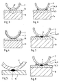
- Figures 1 and 2 schematically show a tube 1 with ribs 2 enlarging the heat transfer surface mounted on its flat side.
- the ribs 2 themselves are formed by a corrugated band whose waves extend at right angles to the tube longitudinal axis and touch the lateral surface of the tube 1 at least in partial regions in the foot region of the ribs 2.
- the tube 1 made of steel. It is provided on its outer surface with a coating of aluminum.
- the ribs 2 are also made of aluminum. From Fig. 4 it can be seen that the rib 2 is provided with a solder layer 3.
- a welding point 4 is shown, which connects the rib 2 with the coating 1 b, and thus produces a material connection between the ribs and the tube.
- a number of three to seven spot welds may already be sufficient to establish a stable connection between the ribs and the tube.
- the rib-tube arrangement shown in Fig. 2 is applied with applied on the rib layer of solder in a soldering oven and heated at a temperature of 550 ° to 620 ° C over a period of 2 to 10 minutes, forming in FIG.
- heat transfer regions 5 which arise through the soldered solder 3 a between the aluminum coating 1 b and the rib 2.
- the heat transfer material may be introduced as powdered solder 3b into the intermediate spaces between rib 2 and coating 1b. This is shown in Fig. 7. In Fig. 8, in turn, the soldered heat transfer is shown. Iron interconnects may form due to the temperature ranges of aluminum.
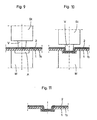
- FIG. 9 shows a section through a tube 1 made of steel provided with a coating 1b made of aluminum and the ribs 2 likewise made of aluminum in the region of a contact surface between these parts.
- the bottom of the tube 1 is shown in FIG. 9 on a die M, which is provided with a recess A. In the area of this recess A, the projection V of a punch St attacks.
- the cross-sectional dimensions of the punch St are in this case smaller than the recess A in the die M.
- the punch St is pressed with its projection V in the recess A in the die M, deforms both the material of Tube 1 and its coating 1 b and the rib 2, so that the illustrated in FIG. 10 form-fitting connection between the provided with the coating 1b tube 1 and the rib 2 results.
- the joint shown in section in FIG. 11 after removal of the die M and die St, shows that the materials of tube 1, coating 1b and rib 2 have keyed together in a positive fit due to the flow occurring during clinching, so that the described Punching creates a reliable connection between rib 2 and tube 1.
- the heat transfer is also generated by the above-described soldering following the clinching.
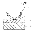
- connection between the rib and the surface of the tube can be made by gluing, as can be seen from Fig. 12.
- a high-temperature ceramic adhesive N is applied in the attachment region of the rib 2.
- the rib 2 is then placed on the splices and pressed. After curing of the adhesive, a permanently fixed connection between the rib 2 and the surface of the tube 1b is given.
- the heat transfer 5 can also be produced by a thermally conductive high-temperature ceramic adhesive N. This is also subsequently introduced in unbound form N 'in the spaces between the rib 2 and coating 1b. This is also apparent from Fig. 7. The thermal conductivity is adjusted by adding fillers such as aluminum. The finished after setting heat transfer 5 through the thermally conductive high-temperature ceramic adhesive N is shown in FIGS. 5 and 8 are also shown.
Description
Die Erfindung betrifft ein Verfahren zur Herstellung eines Wärmetauschers mit einem metallischen Rohr mit einer aluminiumbeschichteten Oberfläche und mit auf der Oberfläche angeordneten die Wärmeübertragungsfläche vergrößernden Rippen aus Aluminium.The invention relates to a method for producing a heat exchanger with a metallic tube having an aluminum-coated surface and having on the surface of the heat transfer surface enlarging ribs made of aluminum.
Derartige Wärmetauscher sind bekannt. Die
Die Anmelderin hat dann in der
Aus der
All diesen bekannten Herstellungsverfahren gemeinsam ist jedoch die relativ aufwendige Fixierung der einzelnen Rippen vor der Herstellung der Wärmeübergangsschichten, wobei die beiden zuletzt genannten Schriften Verfahren offenbaren, die nicht zur Herstellung von großflächigen Industriewärmetauschern geeignet sind. Insgesamt besteht daher der Bedarf an einem wirtschaftlicheren Herstellungsverfahren, das auch in großtechnischen Anwendungen verwendet werden kann.Common to all these known production methods, however, is the relatively complex fixing of the individual ribs prior to the production of the heat transfer layers, the two last-mentioned documents disclosing methods which are not suitable for the production of large-area industrial heat exchangers. Overall, therefore, there is a need for a more economical manufacturing process that can also be used in large-scale applications.
Der Erfindung liegt die Aufgabe zugrunde, ein Verfahren bereitzustellen, mit dem auf einfache und kostengünstige Weise großtechnisch anwendbar ein Wärmetauscher der zuvor beschriebenen Art hergestellt werden kann.The invention has for its object to provide a method by which a heat exchanger of the type described above can be produced in a simple and cost-effective manner industrially applicable.
Erfindungsgemäß erfolgt die Lösung der Aufgabe mit einem Verfahren gemäß Anspruch 1. Es wird also ein Verfahren bereitgestellt, welches sich durch ein Verbinden der beschichteten Oberfläche mit der Rippe durch punktförmiges dauerhaftes Fixieren und dem Herstellen eines großflächigen Wärmeübergangs zwischen Oberfläche und Rippe durch Auffüllen der Zwischenräume zwischen beschichteter Oberfläche und Rippe mit Wärmeleitmaterial auszeichnet.According to the invention, the object is achieved by a method according to
Gemäss der Erfindung handelt es sich bei dem punktförmigen dauerhaften Fixieren um Punktschweißen oder Durchsetzfügen. Die aufwendige flächenmäßige Verspannung der Rippen mit dem Rohr entfällt vor dem Herstellen des Wärmeübergangs. Auch müssen die Bauteile nicht extra entfettet werden, wodurch ein zusätzlicher Arbeitsschritt eingespart werden kann. Des weiteren sind hinsichtlich der herzustellenden Wärmeübergangsqualität an die dafür notwendigen Prozessparameter geringere Anforderungen zu stellen. Das Punktschweißen wird vorteilhaft durch Widerstandsschweißen oder Laserpunktschweißen hergestellt. Auf das metallische Rohr, bei dem es sich um ein aluminiumbeschichtetes Stahlrohr handelt, werden die Aluminiumrippen aufgesetzt und durch Punktschweißen mit dem Rohr verbunden. Somit entsteht eine stabile Struktur zwischen Rohr und Rippe, bei dem allerdings die durch das Punktschweißen hergestellten Berührungspunkte nicht als Wärmeübergang ausreichend sind. In die zwischen der Oberfläche des Rohres und der Rippen bestehenden Zwischenräume ist ein Wärmeleitmaterial vorhanden. Hierbei handelt es sich um Lot. Der Wärmeübergang wird gemäß Anspruch 1 durch Verflüssigen des Lots im Lötverfahren mit anschließender Abkühlung hergestellt. Das Löten erfolgt vorteilhafterweise als Hartlöten bei hohen Temperaturen und kurzen Einwirkzeiten. Das Hartlöten selbst erfolgt in einem Lötofen und vorteilhafterweise unter Schutzgasatmosphäre. Da das Löten selbst aufgrund der hohen Temperaturen zügig durchgeführt wird, sind an die Schutzatmosphäre im Lötofen nur geringe Anforderungen zu stellen. Des weiteren ergeben sich gegenüber bekannten Verfahren erhebliche Vereinfachungen und Einsparungen.According to the invention, the punctiform permanent fixing is spot welding or clinching. The complex areal tension of the ribs with the tube is eliminated before the heat transfer. Also, the components do not have to be degreased extra, so that an additional step can be saved. Furthermore, with regard to the heat transfer quality to be produced, lower requirements must be placed on the necessary process parameters. Spot welding is advantageously produced by resistance welding or laser spot welding. On the metallic tube, which is an aluminum-coated steel tube, the aluminum fins are placed and connected by spot welding to the tube. This results in a stable structure between tube and rib, in which, however, the points of contact produced by the spot welding are not sufficient as heat transfer. In the existing between the surface of the tube and the ribs spaces a Wärmeleitmaterial is present. This is Lot. The heat transfer is produced according to
Eine weitere Lehre der Erfindung sieht vor, daß das Lot auf einfache Weise eingebracht werden kann, indem die Aluminiumrippe bereits mit Lot beschichtet bzw. plattiert ist. Alternativ kann das Lot auch pulverförmig oder bereits verflüssigt in die Zwischenräume eingebracht werden.Another teaching of the invention provides that the solder can be introduced in a simple manner by the aluminum fin is already coated or plated with solder. Alternatively, the solder can also be introduced in powder form or already liquefied in the interstices.
Alternativ ist es ebenfalls möglich, anstelle des Punktschweißens eine formschlüssige Verbindung zwischen Oberfläche des Rohres und der Rippe durch Durchsetzfügen herzustellen. Hierbei werden an vorgegebenen Stellen die Rippen und das Rohr gemeinsam verformt. Bei dem Einsatz eines derartigen Verfahrens kann auf die Beschichtung des Rohres verzichtet werden und je nach Durchsetzfügewerkzeug die Fügung an mehreren Punkten gleichzeitig vorgenommen werden. Der Wärmeübergang läßt sich anschließend auf gleiche Weise herstellen wie zuvor beschrieben.Alternatively, it is also possible to produce a positive connection between the surface of the tube and the rib by clinching instead of spot welding. Here, the ribs and the tube are deformed together at predetermined locations. When using such a method can be dispensed with the coating of the tube and depending on Durchsetzfügewerkzeug the joining at several points are made simultaneously. The heat transfer can then be produced in the same manner as described above.
Auf der Zeichnung sind zwei Ausführungsbeispiele eines nach dem erfindungsgemäßen Verfahren hergestellten Rippenrohres dargestellt, und zwar zeigen:
- Fig. 1
- einen Längsschnitt durch ein Rippenrohr mit auf einer Flachseite des Rohres angebrachten Rippen,
- Fig. 2
- einen Querschnitt durch das Rippenrohr gemäß der Schnittlinie II-II in Fig. 1,
- Fig. 3
- eine vergrößerte Schnittdarstellung des in Fig. 1 eingekreisten Bereiches III,
- Fig. 4
- eine vergrößerte Schnittdarstellung des in Fig. 1 eingekreisten Bereiches IV im unverschweißten Zustand,
- Fig. 5
- eine wiederum vergrößerte Darstellung des Bereiches V in Fig. 3,
- Fig. 6
- eine Schnittansicht durch einen Wärmeübergangsbereich,
- Fig. 7
- eine Schnittdarstellung gemäß Fig. 5 mit nachträglich eingebrachtem Wärmeübergangsmaterial,
- Fig. 8
- eine Schnittansicht mit Schweißverbindung und Wärmeübergang,
- Fig.9
- eine schematische Darstellung des Durchsetzfügens anhand einer Schnittdarstellung im Ausgangszustand,
- Fig. 10
- eine der Fig. 9 entsprechende Darstellung nach Beendigung des Durchsetzfügens,
- Fig. 11
- den Endzustand der Fügestelle in einem Schnitt entsprechend den Fign. 6 und 7 und
- Fig. 12
- eine Schnittansicht eines Beispiele, das nicht im Gegenstand des Ansprüche steht, durch einen verklebten Bereich.
- Fig. 1
- a longitudinal section through a finned tube with mounted on a flat side of the tube ribs,
- Fig. 2
- a cross section through the finned tube according to the section line II-II in Fig. 1,
- Fig. 3
- an enlarged sectional view of the circled in Fig. 1 area III,
- Fig. 4
- an enlarged sectional view of the circled in Fig. 1 area IV in the unwelded state,
- Fig. 5
- an enlarged representation of the area V in FIG. 3 again,
- Fig. 6
- a sectional view through a heat transfer area,
- Fig. 7
- 5 is a sectional view according to FIG. 5 with subsequently introduced heat transfer material, FIG.
- Fig. 8
- a sectional view with welded joint and heat transfer,
- Figure 9
- a schematic representation of the clinching based on a sectional view in the initial state,
- Fig. 10
- 9 a representation corresponding to FIG. 9 after completion of the clinching,
- Fig. 11
- the final state of the joint in a section corresponding to FIGS. 6 and 7 and
- Fig. 12
- a sectional view of an example, which is not in the subject matter of the claims, by a bonded area.
In den Fign. 1 und 2 ist schematisch ein Rohr 1 mit an seiner Flachseite angebrachten die Wärmeübertragungsfläche vergrößernden Rippen 2 dargestellt. Die Rippen 2 selbst werden durch ein gewelltes Band gebildet, dessen Wellen rechtwinklig zur Rohrlängsachse verlaufen und mindestens in Teilbereichen im Fußbereich der Rippen 2 die Mantelfläche des Rohres 1 berühren. Wie aus der vergrößerten Schnittdarstellung des in Fig. 1 eingekreisten Bereiches III in Fig. 3 hervorgeht, besteht beim dargestellten Ausführungsbeispiel das Rohr 1 aus Stahl. Es ist auf seiner Mantelfläche mit einer Beschichtung aus Aluminium versehen. Die Rippen 2 bestehen ebenfalls aus Aluminium. Aus Fig. 4 ist erkennbar, daß die Rippe 2 mit einer Lötschicht 3 versehen ist.In the Fign. Figures 1 and 2 schematically show a
In Fig. 5, welche eine vergrößerte Schnittdarstellung des eingekreisten Bereichs V aus Fig. 3 darstellt, ist ein Schweißpunkt 4 dargestellt, der die Rippe 2 mit der Beschichtung 1b verbindet, und so eine stoffschlüssige Verbindung zwischen den Rippen und dem Rohr herstellt. Je nach Länge des Rohres bzw. der Anzahl der Rippen kann bereits eine Anzahl von drei bis sieben Schweißpunkten ausreichend sein, um eine stabile Verbindung zwischen den Rippen und dem Rohr herzustellen. Wird dann die in Fig. 2 dargestellte Rippen-Rohr-Anordnung mit auf der Rippe aufgebrachter Lotschicht in einen Lötofen eingebracht und bei einer Temperatur von 550° bis 620 ° C über eine Zeitdauer von 2 bis 10 Minuten erwärmt, bilden sich die in Fig. 6 dargestellten Wärmeübergangsbereiche 5, die durch das verlötete Lot 3a zwischen der Aluminiumbeschichtung 1 b und der Rippe 2 entstehen. Alternativ kann anstelle einer Lötschicht 3 das Wärmeübergangsmaterial als pulverförmiges Lot 3b in die Zwischenräume zwischen Rippe 2 und Beschichtung 1b eingebracht werden. Dieses ist in Fig. 7 dargestellt. In Fig. 8 ist dann wiederum der verlötete Wärmeübergang dargestellt. Es können sich aufgrund der Temperaturbereiche von Aluminium Eisenzwischenverbindungen bilden.In Fig. 5, which is an enlarged sectional view of the circled portion V of Fig. 3, a
Alternativ zu den Verschweißungen kann die Verbindung zwischen Rippe und Oberfläche des Rohrs auch hergestellt werden, indem eine punktuelle Durchsetzfügung, wie sie in den Fign. 9 bis 11 schematisch dargestellt ist, durchgeführt wird. Fig. 9 zeigt dabei einen Schnitt durch ein mit einer Beschichtung 1b aus Aluminium versehenes Rohr 1 aus Stahl und den Rippen 2 ebenfalls aus Aluminium im Bereich einer Berührungsfläche zwischen diesen Teilen. Die Unterseite des Rohres 1 liegt gemäß Fig. 9 auf einer Matritze M, die mit einer Aussparung A versehen ist. Im Bereich dieser Aussparung A greift der Vorsprung V eines Stempels St an. Die Querschnittsabmessungen des Stempels St sind hierbei geringer als die Aussparung A in der Matritze M.As an alternative to the welds, the connection between the rib and the surface of the pipe can also be made by using a point-by-point joining as shown in FIGS. 9 to 11 is shown schematically, is performed. FIG. 9 shows a section through a
Wenn nunmehr gemäß Fig. 10 der Stempel St mit seinem Vorsprung V in die Aussparung A in der Matritze M gedrückt wird, verformt sich sowohl das Material des Rohres 1 und seiner Beschichtung 1 b als auch die Rippe 2, so daß sich die in der Fig. 10 dargestellte formschlüssige Verbindung zwischen dem mit der Beschichtung 1b versehenen Rohr 1 und der Rippe 2 ergibt.Now, as shown in FIG. 10, the punch St is pressed with its projection V in the recess A in the die M, deforms both the material of
Die nach Entfernen des aus Matritze M und Stempel St bestehenden Werkzeugs in Fig. 11 im Schnitt dargestellte Fügestelle zeigt, daß sich die Materialien von Rohr 1, Beschichtung 1b und Rippe 2 aufgrund des beim Durchsetzfügen eingetretenen Fließens formschlüssig ineinander verkeilt haben, so daß das beschriebene Durchsetzfügen eine zuverlässige Verbindung zwischen Rippe 2 und Rohr 1 schafft. Der Wärmeübergang wird im Anschluß an das Durchsetzfügen ebenfalls durch das zuvor beschriebene Löten erzeugt.The joint, shown in section in FIG. 11 after removal of the die M and die St, shows that the materials of
In einem Beispiel, das nicht im Gegenstand des Ansprüche steht, kann die Verbindung zwischen Rippe und Oberfläche des Rohrs durch Kleben erfolgen, wie es aus Fig. 12 ersichtlich ist. Auf die Rohroberfläche 1b wird ein Hochtemperatur-Keramikkleber N im Befestigungsbereich der Rippe 2 aufgebracht. Die Rippe 2 wird anschließend auf die Klebestellen aufgesetzt und angedrückt. Nach Aushärten des Klebers ist eine dauerhaft feste Verbindung zwischen Rippe 2 und Oberfläche des Rohrs 1b gegeben.In an example, which is not in the subject of the claims, the connection between the rib and the surface of the tube can be made by gluing, as can be seen from Fig. 12. On the
Alternativ zum durch Löten hergestellten Wärmeübergang, aber nicht im Gegenstand des Ansprüche, kann der Wärmeübergang 5 auch durch einen thermisch leitfähigen Hochtemperatur-Keramikkleber N hergestellt werden. Dieser wird ebenfalls nachträglich in nicht abgebundener Form N' in die Zwischenräume zwischen Rippe 2 und Beschichtung 1b eingebracht. Dieses ist aus Fig. 7 ebenfalls ersichtlich. Die thermische Leitfähigkeit wird durch Zugabe von Füllstoffen wie Aluminium eingestellt. Der nach dem Abbinden fertige Wärmeübergang 5 durch den thermisch leitenden Hochtemperatur-Keramikkleber N ist in den Fign. 5 und 8 ebenfalls gezeigt.As an alternative to the heat transfer produced by soldering, but not in the subject matter of the claims, the
- 11
- Rohrpipe
- 1a1a
- Fe-GrundkörperFe-base
- 1b1b
- Al-BeschichtungAl-coating
- 1c1c
- Al-Fe-ZwischenverbindungsbereichAl-Fe-interconnection region
- 22
- Ripperib
- 33
- Lotschichtsolder layer
- 3a3a
- verlötetes Lotsoldered solder
- 3b3b
- pulverförmiges Lotpowdered solder
- 44
- SchweißpunktWeldingSpot
- 55
- WärmeübergangsbereichHeat transfer area
- AA
- Aussparungrecess
- MM
- Matritzefemale mold
- StSt
- Stempelstamp
- VV
- Vorsprunghead Start
- NN
- Hochtemperatur-KeramikkleberHigh-temperature ceramic adhesive
- N'N '
- nicht abgebundener Hochtemperatur-Keramikkleberuncured high-temperature ceramic adhesive
Claims (7)
- A method for producing a heat exchanger with a metallic pipe (1), with an aluminium-coated surface (1b) and with ribs (2) which are arranged on the surface (1b), enlarge the heat-transfer surface and are formed from an undulating band of ribs made of aluminium, in which the band of ribs is fixed on the coated surface (1b) in a spot-like manner by welding or clinching to the pipe (19) with a number of points which is just sufficient according to the length of the pipe (1) or the number of ribs (2), that a stable connection is produced, with a clamping of the ribs (2) with the pipe (1) over the surface not being made, that solder is present as a heat conductive material in the cavities present between the surface of the pipe (1) and the rib (2) for forming heat transfer sections (5), and the rib-and-pipe arrangement is introduced into a soldering furnace and the solder is liquefied by heating and that the solder is cooled thereafter.
- A method according to claim 1,
characterized in that
the band of ribs is fixed in a spot-like manner by means of three to seven spot welds to the coated surface (1 b) of the pipe (1). - A method according to claim 1 or 2,
characterized in that
spot-welding is used for spot-like permanent fixing. - A method according to claim 1,
characterized in that
soldering is carried out as brazing. - A method according to one of the claims 1 to 4,
characterized in that
soldering occurs with short times of exposure. - A method according to one of the claims 1 to 5,
characterized in that
the ribs (2) are coated and/or plated with solder (3). - A method according to one of the claims 1 to 5,
characterized in that
the powdery solder is introduced into the cavities.
Priority Applications (2)
| Application Number | Priority Date | Filing Date | Title |
|---|---|---|---|
| DE50307950T DE50307950D1 (en) | 2003-01-27 | 2003-01-27 | Method for producing a heat exchanger |
| EP03001704A EP1440759B8 (en) | 2003-01-27 | 2003-01-27 | Method for manufacturing a heat exchanger |
Applications Claiming Priority (1)
| Application Number | Priority Date | Filing Date | Title |
|---|---|---|---|
| EP03001704A EP1440759B8 (en) | 2003-01-27 | 2003-01-27 | Method for manufacturing a heat exchanger |
Publications (3)
| Publication Number | Publication Date |
|---|---|
| EP1440759A1 EP1440759A1 (en) | 2004-07-28 |
| EP1440759B1 true EP1440759B1 (en) | 2007-08-15 |
| EP1440759B8 EP1440759B8 (en) | 2007-11-07 |
Family
ID=32524209
Family Applications (1)
| Application Number | Title | Priority Date | Filing Date |
|---|---|---|---|
| EP03001704A Expired - Fee Related EP1440759B8 (en) | 2003-01-27 | 2003-01-27 | Method for manufacturing a heat exchanger |
Country Status (2)
| Country | Link |
|---|---|
| EP (1) | EP1440759B8 (en) |
| DE (1) | DE50307950D1 (en) |
Families Citing this family (4)
| Publication number | Priority date | Publication date | Assignee | Title |
|---|---|---|---|---|
| DE102010004973A1 (en) | 2010-01-18 | 2011-07-21 | Behr GmbH & Co. KG, 70469 | Heat transmitter e.g. exhaust gas heat transmitter, for exhaust gas return-and cooling arrangement to transmit heat from exhaust gas of combustion engine to cooling fluid in motor car, has cabinet and tube connected using adhesive |
| DE102010010415A1 (en) * | 2010-03-05 | 2011-09-08 | Bayerische Motoren Werke Aktiengesellschaft | Method for producing a corrosion-resistant laser welding connection between two components and arrangement of two components welded together |
| EP2574453B1 (en) | 2011-09-30 | 2014-12-10 | Aleris Aluminium GmbH | Method for joining an aluminium alloy fin to a steel tube and heat exchanger made therefrom |
| WO2018053585A1 (en) * | 2016-09-21 | 2018-03-29 | Air-Radiators Pty Ltd | Heat exchanger and components and methods therefor |
Family Cites Families (7)
| Publication number | Priority date | Publication date | Assignee | Title |
|---|---|---|---|---|
| JPS61165268A (en) * | 1985-01-17 | 1986-07-25 | Hitachi Zosen Corp | Production of heat exchanger element |
| US4949543A (en) * | 1989-09-12 | 1990-08-21 | Modine Manufacturing Company | Tube and fin assembly for heat exchangers in power plants |
| DE59610403D1 (en) * | 1996-08-03 | 2003-06-05 | Balcke Duerr Gmbh | Process for the production of corrosion-resistant heat exchangers |
| EP0823296A3 (en) * | 1996-08-03 | 2000-03-01 | Balcke-Dürr GmbH | Method of manufacturing corrosion resistant heat exchangers |
| US6450253B1 (en) * | 1998-11-27 | 2002-09-17 | Calsonic Kansei Corporation | Tank of heat exchanger |
| CN1451091A (en) * | 2000-04-14 | 2003-10-22 | 阿维德塞马洛伊有限责任公司 | Notched finned heat sink |
| US6748656B2 (en) * | 2000-07-21 | 2004-06-15 | Ats Automation Tooling Systems Inc. | Folded-fin heatsink manufacturing method and apparatus |
-
2003
- 2003-01-27 DE DE50307950T patent/DE50307950D1/en not_active Expired - Fee Related
- 2003-01-27 EP EP03001704A patent/EP1440759B8/en not_active Expired - Fee Related
Also Published As
| Publication number | Publication date |
|---|---|
| DE50307950D1 (en) | 2007-09-27 |
| EP1440759B8 (en) | 2007-11-07 |
| EP1440759A1 (en) | 2004-07-28 |
Similar Documents
| Publication | Publication Date | Title |
|---|---|---|
| EP3265739B1 (en) | 3d printed heating surface element for a plate heat exchanger | |
| EP1811245B1 (en) | Modular solar panel | |
| DE2339499A1 (en) | COOLER STRUT TO CONNECT THE LATERAL JAWS, COLLECTION PIPES AND WATER TANK OF COOLERS | |
| EP0781623B1 (en) | Process for manufacturing brazed aluminium heat exchangers | |
| DE102007040848A1 (en) | Heat exchanger and process for its preparation | |
| DE102012023800A1 (en) | Heat exchanger tube, heat exchanger tube assembly and method of making same | |
| EP0819497B1 (en) | Process for manufacturing a finned tube | |
| DD232854A5 (en) | HOT PRESS WELDING | |
| DE102006002932A1 (en) | Heat exchanger tube has internal chamber extends from center of tube past location to interior surface of second narrow side | |
| DE112016003449T5 (en) | Heat exchanger and method for producing the same | |
| DE102013222258A1 (en) | Process for producing a heat exchanger, in particular a sorption heat exchanger | |
| CH635009A5 (en) | METHOD FOR CONNECTING A METAL PIPE TO A METAL SHEET AND ABSORPTION PLATE PRODUCED BY THE METHOD. | |
| DE602004008782T2 (en) | HEAT EXCHANGERS AND THEIR MANUFACTURING | |
| EP1440759B1 (en) | Method for manufacturing a heat exchanger | |
| DE102011051935A1 (en) | Method for manufacturing heat exchanger i.e. motor car heat exchanger, involves producing welding points by resistance welding of heat exchanger inner surface with turbulator insert, and coupling inner surface with insert by soldering | |
| EP0823296A2 (en) | Method of manufacturing corrosion resistant heat exchangers | |
| DE69917941T2 (en) | END CHAMBER FOR HEAT EXCHANGERS | |
| EP0822025B1 (en) | Method of manufacturing corrosion resistant heat exchangers | |
| DE4404928A1 (en) | Heater of metal tubes intimately connected to one another, and method of producing it | |
| DE2716364A1 (en) | PROCESS FOR MANUFACTURING HEAT EXCHANGERS WITH PIPES AND RADIATING SECTIONS, AND EXCHANGERS MANUFACTURED BY THE PROCESS | |
| DE102012023801A1 (en) | Heat exchanger tube, heat exchanger tube assembly and method of making same | |
| DE3301858A1 (en) | SOLAR COLLECTOR BOARD AND METHOD FOR THEIR PRODUCTION | |
| CH384008A (en) | Process for the manufacture of heat exchangers | |
| DE102015201808A1 (en) | Heat exchanger tube assembly and method of making same | |
| DE2834767A1 (en) | Haulage vehicle cooling radiator - consists of plates which are punched to form tapering collars that are welded together to form flow channels |
Legal Events
| Date | Code | Title | Description |
|---|---|---|---|
| PUAI | Public reference made under article 153(3) epc to a published international application that has entered the european phase |
Free format text: ORIGINAL CODE: 0009012 |
|
| AK | Designated contracting states |
Kind code of ref document: A1 Designated state(s): AT BE BG CH CY CZ DE DK EE ES FI FR GB GR HU IE IT LI LU MC NL PT SE SI SK TR |
|
| AX | Request for extension of the european patent |
Extension state: AL LT LV MK RO |
|
| 17P | Request for examination filed |
Effective date: 20040819 |
|
| 17Q | First examination report despatched |
Effective date: 20041216 |
|
| AKX | Designation fees paid |
Designated state(s): DE GB IT |
|
| GRAP | Despatch of communication of intention to grant a patent |
Free format text: ORIGINAL CODE: EPIDOSNIGR1 |
|
| GRAS | Grant fee paid |
Free format text: ORIGINAL CODE: EPIDOSNIGR3 |
|
| GRAA | (expected) grant |
Free format text: ORIGINAL CODE: 0009210 |
|
| AK | Designated contracting states |
Kind code of ref document: B1 Designated state(s): DE GB IT |
|
| REG | Reference to a national code |
Ref country code: GB Ref legal event code: FG4D Free format text: NOT ENGLISH |
|
| RAP2 | Party data changed (patent owner data changed or rights of a patent transferred) |
Owner name: SPX-COOLING TECHNOLOGIES GMBH |
|
| GBT | Gb: translation of ep patent filed (gb section 77(6)(a)/1977) |
Effective date: 20070815 |
|
| REF | Corresponds to: |
Ref document number: 50307950 Country of ref document: DE Date of ref document: 20070927 Kind code of ref document: P |
|
| PLBE | No opposition filed within time limit |
Free format text: ORIGINAL CODE: 0009261 |
|
| STAA | Information on the status of an ep patent application or granted ep patent |
Free format text: STATUS: NO OPPOSITION FILED WITHIN TIME LIMIT |
|
| 26N | No opposition filed |
Effective date: 20080516 |
|
| PGFP | Annual fee paid to national office [announced via postgrant information from national office to epo] |
Ref country code: DE Payment date: 20090302 Year of fee payment: 7 |
|
| PGFP | Annual fee paid to national office [announced via postgrant information from national office to epo] |
Ref country code: GB Payment date: 20090129 Year of fee payment: 7 |
|
| PGFP | Annual fee paid to national office [announced via postgrant information from national office to epo] |
Ref country code: IT Payment date: 20090127 Year of fee payment: 7 |
|
| GBPC | Gb: european patent ceased through non-payment of renewal fee |
Effective date: 20100127 |
|
| PG25 | Lapsed in a contracting state [announced via postgrant information from national office to epo] |
Ref country code: DE Free format text: LAPSE BECAUSE OF NON-PAYMENT OF DUE FEES Effective date: 20100803 |
|
| PG25 | Lapsed in a contracting state [announced via postgrant information from national office to epo] |
Ref country code: GB Free format text: LAPSE BECAUSE OF NON-PAYMENT OF DUE FEES Effective date: 20100127 |
|
| PG25 | Lapsed in a contracting state [announced via postgrant information from national office to epo] |
Ref country code: IT Free format text: LAPSE BECAUSE OF NON-PAYMENT OF DUE FEES Effective date: 20100127 |