EP1440625A2 - Batch-cycle type heat-treatment apparatus for treating of material like mash fodder as well as a method using such an apparatus for treatment of material - Google Patents
Batch-cycle type heat-treatment apparatus for treating of material like mash fodder as well as a method using such an apparatus for treatment of material Download PDFInfo
- Publication number
- EP1440625A2 EP1440625A2 EP04075200A EP04075200A EP1440625A2 EP 1440625 A2 EP1440625 A2 EP 1440625A2 EP 04075200 A EP04075200 A EP 04075200A EP 04075200 A EP04075200 A EP 04075200A EP 1440625 A2 EP1440625 A2 EP 1440625A2
- Authority
- EP
- European Patent Office
- Prior art keywords
- fodder
- air
- heat
- batch
- stirring blades
- Prior art date
- Legal status (The legal status is an assumption and is not a legal conclusion. Google has not performed a legal analysis and makes no representation as to the accuracy of the status listed.)
- Withdrawn
Links
Images


Classifications
-
- A—HUMAN NECESSITIES
- A23—FOODS OR FOODSTUFFS; TREATMENT THEREOF, NOT COVERED BY OTHER CLASSES
- A23N—MACHINES OR APPARATUS FOR TREATING HARVESTED FRUIT, VEGETABLES OR FLOWER BULBS IN BULK, NOT OTHERWISE PROVIDED FOR; PEELING VEGETABLES OR FRUIT IN BULK; APPARATUS FOR PREPARING ANIMAL FEEDING- STUFFS
- A23N17/00—Apparatus specially adapted for preparing animal feeding-stuffs
- A23N17/02—Fodder mashers
-
- A—HUMAN NECESSITIES
- A23—FOODS OR FOODSTUFFS; TREATMENT THEREOF, NOT COVERED BY OTHER CLASSES
- A23N—MACHINES OR APPARATUS FOR TREATING HARVESTED FRUIT, VEGETABLES OR FLOWER BULBS IN BULK, NOT OTHERWISE PROVIDED FOR; PEELING VEGETABLES OR FRUIT IN BULK; APPARATUS FOR PREPARING ANIMAL FEEDING- STUFFS
- A23N17/00—Apparatus specially adapted for preparing animal feeding-stuffs
- A23N17/004—Apparatus specially adapted for preparing animal feeding-stuffs for treating by application of heat, e.g. by means of potato cookers
Definitions
- the invention relates to a batch-cycle type heat-treatment apparatus for treating of material like mash fodder comprising:
- the invention furthermore relates to a heat treatment method using such a batch-cycle type heat treatment apparatus for heating material like mash fodder.
- mash fodder material like meat or as fodder for domestic animals, mash fodder, pelleted fodder, or crumbled fodder has been used, wherein the pelleted fodder and the crumbled fodder are heated with steam as pretreatment of processing, whereas almost the fodder for chickens is so-called mash fodder, in which raw materials are only crushed and mixed without being absolutely heated.
- the mash fodder is powder, while the heat treatment for pasteurization is difficult, it is required to dry and further cool the fodder after heating, so that it is difficult in efficiently performing each process.
- Heat-treatment equipment for heating, and then drying, and further cooling the mash fodder is proposed in Japanese Unexamined Patent Application Publication No. 2000-189136, for example.
- This heat-treatment equipment has a heat-treatment apparatus and a drying and cooling apparatus linked thereto, in which heat-treated fodder is fed to drying and cooling apparatus via a duct, which in turn is dried within the drying and cooling apparatus by spraying hot air thereto from lower through upper portions thereof, and further cooled by spraying cooling air thereto within the same drying and cooling apparatus similarly from the lower portion thereof.
- fodder is heated with steam so as to be dried and cooled thereafter, enabling the mash fodder to be pasteurized.
- This proposal is that the heat-treatment is performed while fodder is agitated with a mixer, and after the heat treatment, the fodder is transferred to a dryer/cooler so as to perform drying and cooling thereon.
- powder mash fodder can even be pasteurized by heating it with steam, and then the high-temperature fodder containing moisture is dried and further cooled, so that hygienic fodder can be provided, preventing animal diseases.
- the process is basically continuous, so that steam is continuously sprayed on continuously flowing fodder, and then drying and cooling are performed thereon.
- the dryer/cooler is a conventional system used in feed mills, in which air is only sprayed from the bottom up, so that there is a problem in the powder mash fodder that an air passage is liable to be produced.
- Material which has been treated in the heat treatment unit will be temporarily stored in the buffer hopper to be heated again. Also material which accidently leaves the heat treatment unit before the heat treatment in the heat treatment unit has been finished, will be heated in the buffer hopper so that no material will enter the dryer cooler without being heated sufficiently.
- An embodiment of the batch-cycle type heat treatment apparatus is characterized in that the dryer cooler provided with an agitator comprising a rotational central shaft and stirring blades having air injectors being capable of spraying air so as to dry and/or heat/cool the material by injecting air while the material being stirred.
- the invention furthermore relates to a batch-cycle type heat-treatment apparatus for treatment of material like mash fodder comprising a dryer cooler provided with an agitator comprising a rotational central shaft and stirring blades having air injectors being capable of spraying air so as to dry and/or heat/cool the material by injecting air while the material is being stirred.
- Air will be used for drying and/or heating/cooling the material whereby the air will be sprayed to the inside of the material while the material is being steered.
- the drying and/or heating/cooling efficiencies will be extremely high and the material will be uniformly dried and/or heated/cooled.
- FIG. 1 A basic embodiment according to the present invention is illustrated in Fig. 1.
- a hopper A in which mash fodder is pumped, and a heat-treatment apparatus 1 according to the present invention is linked thereto.
- the fodder is fed to the heat-treatment apparatus 1.
- the heat-treatment apparatus 1 is provided with a batch type mixer, i.e., a twin shaft paddle mixer 22, arranged on an upper portion inside the device.
- a batch type mixer i.e., a twin shaft paddle mixer 22
- the paddle mixer 22 has two shafts 221 with axes arranged in parallel to a surface of an upper opening 10 of the heat-treatment apparatus body 1, i.e., in a direction perpendicular to the inside direction of the body 1, each shaft 221 having a plurality of paddles 222 protruded from the axis, so that by rotating the paddle mixer 22, the paddles 222 are rotated for stirring fodder.
- a first room 2 containing the twin shaft paddle mixer 22 can be formed by closing the openable lid 23.
- steam spray nozzles 21 are arranged for spraying steam into the first room 2, so as to form the heat-treatment unit 2 for spraying steam so as to perform the heat-treatment while the fodder within the first room 2 being stirred.
- the fodder can be efficiently and uniformly heated to the inside thereof.
- the batch type mixer i.e., the paddle mixer 22 is rotated during the steam spraying, but, for example, after heating and stirring fodder by rotating the paddle mixer 22 while steam being sprayed for a predetermine period of time, only the steam is stopped spraying, only the paddle mixer 22 is further rotated for a predetermine period of time, so that the heat-treatment of the fodder is enabled extremely effectively.
- the steam is stopped spraying and only the paddle mixer 22 is rotated so as to further stir the fodder already heated at a high temperature and to uniformly heat the entire fodder, so that desired heat-treatment can be absolutely effectively performed by having a sufficient heating time.
- the mixing of fodder is further progressed while a moisture content of the fodder is uniformized so as to prevent a lump (cake) from being produced as well as to prevent the fodder from sticking to and remaining on the surface of the inside of the first room 2 and the paddle mixer 22.
- the steam is stopped spraying, so that a sufficient heating time can be secured by further continuing the stirring of the paddle mixer 22 for a predetermined period of time and the steam is efficiently exerted inside the fodder uniformly, enabling the Salmonella sterilizing efficiency of the entire fodder to be improved.
- the reason why the paddle mixer 22 is the twin shaft is to further promote the stirring between the fodder and steam; it is not limited to the twin shaft but a multiple-shaft type may be of course used.
- the heat-treatment unit 2 constituted of the first room 2 of the heat-treatment apparatus is provided with a buffer hopper 3 arranged below the heat-treatment unit 2 and having an on-off valve 34.
- the hopper 3 is a substantially conical shape protruded downward and having the on-off valve 34 at the cone point.
- the second room 3 is for temporarily storing the heated fodder if required as a preliminary step toward the drying and cooling performed by the dryer/cooler 4.
- the heated fodder is transferred to the dryer/cooler 4 if it is possible, according to need such as a case where the fodder heated earlier is yet dried and cooled by the dryer/cooler 4, the fodder heated already can be temporarily stored in the second room 3.
- the buffer hopper 3 which is the second room 3, in particular, in a case where the fodder being stirred and heated in the first room 2 has leaked from the first room 2, the leaked fodder can be prevented from being mixed into the subsequent dryer/cooler 4.
- the fodder heated insufficiently is prevented from being mixed into the dryer/cooler 4 as it is, enabling complete pasteurizing to be performed.
- the buffer hopper 3 it is preferable to heat the buffer hopper 3. That is, this is for securely pasteurizing dropped fodder by heating it with the heated buffer hopper 3 if insufficiently heated fodder drops.
- the buffer hopper 3 may be that at least fodder contacting the inner wall of the hopper 3 is heated with known heating means such as heating with hot water passed through a double walled structure of the buffer hopper 3 or heating with electricity.
- the structure shown in this figure has an electrical heating surface 31 formed on an inner wall 33 of the buffer hopper 3 so as to heat the fodder dropped on the surface by heating the electrical heating surface 31.
- the heat-treatment apparatus 1 itself be thermally insulated for preventing temperature fall of the device 1 and condensation thereof.
- the fodder leaking from the first room 2 abuts the baffle 32 so as to be deflected and dropped on the electrical heating surface 31.
- the fodder dropped in the buffer hopper 3 drops on the inner wall 33 of the buffer hopper 3 directly to be heated thereon by contacting the electrical heating surface 31, whereas if the fodder drops on the on-off valve 34, it may be not heated leaving not pasteurized fodder, so that the dropping direction is restricted with the baffle 32 so that the entire dropped fodder drops on the inner wall 33 of the buffer hopper 3.
- the heat-treatment apparatus 1 has a third room 4 arranged in the lower portion of the device 1, i.e., below the second room 3.
- the third room 4 is the dryer/cooler 4 for drying and cooling the fodder.
- the third room 4 constituting the dryer/cooler 4 is arranged in a lower portion forming the heat-treatment apparatus 1, and it is preferable that the shape of the third room 4 be a substantial circular cone having an apex at the bottom or a substantial circular cylinder.
- the shape of the third room 4 may be a polygonal substantial pyramid having an apex at the bottom and being close to a substantial circular cone or may be a polygonal substantial prism close to a substantial circular cylinder.
- a dryer/cooler of a conventional heat-treatment apparatus has been frequently rectangular shaped, so that dead corners are formed at the four corners when air is sprayed for drying and cooling fodder so as to inhibit the drying and cooling effects while condensation being liable to be produced and the fodder being liable to remain when it is discharged. Whereas, by the shapes mentioned above, the remains at the corners and the disadvantages can be prevented.
- a side surface 42 is linearly or obliquely formed downward, the inner surface is smooth, preventing powder fodder from remaining.
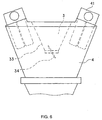
- a dust collection filter 41 is arranged, and when air is sprayed for drying and cooling fodder, the air is exhausted outside through the dust collection filter 41.
- a bottom plate 43 on which fodder can be placed, is arranged in a lower portion forming the third room 4, and the bottom plate 43 is provided with holes 44, through which air is sprayed for blowing the fodder placed on the bottom plate 43 through upward from the bottom of the fodder.
- the fodder on the bottom plate 43 can exhaust air from the bottom thereof through the holes 44.
- agitator 45 is arranged.
- the agitator 45 can stir fodder in a drying process and a cooling process, and it stirs the fodder so as to rapidly dry or cool the entire fodder uniformly during the spraying air passing from the bottom through the holes 44 of the bottom plate 43.
- the air is supplied from an aeration pipe 46 therethrough.
- the agitator 45 shown in the figure has a rotational central shaft 451 having a plurality of stirring blades 452 at the end extremity while the stirring blades 452 are located in a lower portion forming the third room 4, which is the dryer/cooler 4 and enables the stirring blades 452 to be rotated in a direction horizontal to the bottom plate 43 in the third room 4.
- the fodder within the third room 4 is stirred by the stirring blades 452 as well as is evened so as to flatten the product layer.
- Such a stirring blades 452 is provided with air injectors 453 arranged on side faces in the direction opposite to the rotational direction of the blades 452 for spraying air therefrom.
- the stirring blades 452 of the agitator 45 can spray air to the inside of fodder in the direction opposite to the rotational direction while the fodder being stirred, so that air can pervade the entire inside of the fodder absolutely efficiently, securing the drying and cooling effects.
- a number of the air injectors 453 formed on side faces in the direction opposite to the rotational direction of the stirring blades 452 can allow air to pervade the inside of the fodder extensively by injecting air into spaces of fodder produced by the stirring from a number of the injectors 453; the structure is not limited to this and alternatively, small number of air injectors 453 may inject air at high speed, or instead of the injectors 453 formed on side faces in the direction opposite to the rotational direction of the blades 452, the air injectors 453 may be formed on the upper or lower side faces of the stirring blades 452 or side faces in the rotational direction as well as on places of the combination of these places.
- the structure is not limited to that the holes 44 for spraying air are provided on the bottom as mentioned above while air being injected from the air injectors 453 formed on the stirring blades 452, it may be of course to provide holes for spraying air to fodder formed on places other than the bottom, or it may also be to provide only the air injection from the air injectors 453 formed on the stirring blades 452 without the air spraying from the bottom.
- the bottom plate 43 in the third room 4 combines the holes 44 for spraying air into the third room 4 with a discharge gate, so that air can be sprayed from the holes 44 when the bottom plate 43 is closed, and when discharging fodder, the bottom plate 43 is opened so as to drop and discharge the fodder outside.
- a valve 47 is used when fodder is finally discharged outside, and when air is supplied from the aeration pipe 46, by closing the valve 47, the supplied air is sprayed from the holes 44 to the third room 4.
- the air from the air injectors 453 formed on the stirring blades 452 is sprayed over the entire dryer/cooler 4 so as to clean the inside thereof, enabling the residual fodder to be a minimum.
- Fig. 2 is a fragmentary end view of an example of a shape of the stirring blades 452 of the agitator 45 shown in Fig. 1.
- the four stirring blades 452 are provided in total at the end extremity of the rotational central shaft 451, each stirring blade 452 having the five air injectors 453, for spraying air.
- the air spraying from the air injectors 453 is performed by supplying air from the rotational central shaft 451.
- Fig. 3 is a drawing showing an example of airflow within the rotational central shaft 451 for spraying air from the air injectors 453 of the stirring blades 452 of the agitator 45.
- a motor 48 is provided for rotating the agitator 45 while the rotational central shaft 451 is provided with a central cavity 454 for passing air.
- a hollow aeration cover 51 is also provided for covering the shaft 451 and further connected to an aeration pipe 52.
- the aeration cover 51 is fixed, and the rotational central shaft 451 rotatably penetrates the center of the aeration cover 51.
- the stirring blades 452 may be provided with cavities, which are linked to a plurality of the air injectors 453, for spraying the air in the cavities, or each of the air injectors 453 may have a pipe linking the hollow linking part 456 to each air injector 453 for spraying air from the air injectors 453.
- Any structure may be satisfactory as long as at least it is spraying air from the air injectors 453 via the stirring blades 452 from the rotational central shaft 451.
- the air outside may be supplied compulsorily by a fan arranged separately, and it is preferable that air be supplied at a high speed.
- the air be switchable between hot air and cold air. That is, in the drying process, the hot air is sprayed and further in the cooling process, the cold air is sprayed for drying and cooling fodder.
- the switching between hot air and cold air may employ a known example such as a structure using a heater.
- a structure may also be satisfactory, in which normal air, i.e., the cold air, is only sprayed without the switching.
- the dryer/cooler 4 shown in the figures is of a single batch cycle type, in which the heat-treatment is first performed in the first room 2, which is the heat-treatment unit, and then, the fodder stored in the second room 3 is fed to the dryer/cooler 4 as needed by an amount of one batch.
- the entire fodder can be efficiently dried.
- the entire fodder can be efficiently cooled.
- the agitator 45 is stopped rotating and the fodder is discharged downward by opening the bottom plate 43.
- the rotation of the agitator 45 may be of course continued to rotate for minimizing the residual fodder in the third room 4 to a minimum.
- Fig. 4 is a drawing of an example of the bottom plate 43.
- the bottom plate 43 is constituted of a number of bottom-plate components 430, each component 430 comprising a closing shaft 431 and a plate 432, and each component 430 is structured so that the plate 432 is openable and closable about the closing shaft 431 as an axis.
- bottom-plate components 430 are simultaneously opened and closed in conjunction with each other.
- Opening and closing states of a bottom-plate component 430a and a bottom-plate component 430b shown in the figure are different from each other for being evident from descriptions, in which the bottom-plate component 430a shows a state of structuring the bottom plate 43 by the closure thereof while the bottom-plate component 430b shows a state that the component 430b is slightly opened, i.e., a partly opened state.
- the bottom-plate component 430a, the bottom-plate component 430b, and the other bottom-plate components 430 are entirely operated in synchronous with each other.
- the plate 432 of the bottom-plate component 430 is provided with a number of the holes 44 for passing air through.
- Air can be sprayed through the holes 44 to the fodder on the bottom plate 43 from the bottom side upwardly.
- the hole 44 may have any diameter as long as mash fodder does not drop, and the shapes, the positional arrangement, and the number of the holes 44 can be arbitrarily set up according to necessities.
- Figs. 5 and 6 are drawings showing an example of the arrangement of the filters 41 in the third room 4 and the situation of exhausted air in the dryer/cooler 4.
- a number of the filters 41 are arranged in the circumferential direction for efficiently exhausting air from the third room 4.
Landscapes
- Life Sciences & Earth Sciences (AREA)
- Chemical & Material Sciences (AREA)
- Engineering & Computer Science (AREA)
- Food Science & Technology (AREA)
- Polymers & Plastics (AREA)
- Fodder In General (AREA)
- Apparatuses For Bulk Treatment Of Fruits And Vegetables And Apparatuses For Preparing Feeds (AREA)
- Drying Of Solid Materials (AREA)
Abstract
Description
Claims (10)
- A batch-cycle type heat-treatment apparatus for treatment of material like mash fodder comprising:wherein at least the inner surface of the buffer hopper (3) can be heated so as to have the buffer hopper (3) being capable of heating the material dropping from the heat-treatment unit (2).a heat-treatment unit (2) for heating the material; anda dryer cooler (4) disposed below the heat-treatment unit (2) for drying and cooling the heated material, characterized in thata buffer hopper (3) having an on-off valve (34) is disposed between the heat-treatment unit (2) and the dryer cooler (4),
- A batch-cycle type heat treatment apparatus according to claim 1, characterized in that the dryer cooler (4) provided with an agitator (45) comprising a rotational central shaft (451) and stirring blades (452) having air injectors (453) being capable of spraying air so as to dry and/or heat/cool the material by injecting air while the material being stirred.
- A batch-cycle type heat-treatment apparatus for treatment of material like mash fodder comprising a dryer cooler (4) provided with an agitator (45) comprising a rotational central shaft (451) and stirring blades (452) having air injectors (453) being capable of spraying air so as to dry and/or heat/cool the material by injecting air while the material is being stirred.
- A batch-cycle type heat treatment apparatus according to claim 3, characterized in that the apparatus comprising a heat treatment unit (2) for heating the material, whereby the dryer cooler (4) is disposed below the heat treatment unit (2) for drying and cooling the heated material.
- A batch-cycle type heat treatment apparatus according to one of the preceding claims, characterized in that the heat treatment unit (2) comprises a batch mixer having a twin shaft paddle mixer (22) as well as means for spraying steam to the material so as to perform the heat treatment.
- A batch-type heat treatment apparatus according to one of the preceding claims, characterized in that the shape of the dryer cooler (4) is one of a substantial circular cone having an apex at the bottom, a polygonal substantial pyramid having an apex at the bottom and being close to a substantial circular cone, a substantial circular cylinder, and a polygonal substantial prism being close to a substantial circular cylinder.
- An apparatus according to one of the preceding claims 2-6, wherein the stirring blades (452) are located in a bottom portion forming the dryer cooler (4) and rotated in a direction parallel to a bottom plate (43) of the dryer cooler (4), and
wherein a plurality of the air injectors (453) being capable of spraying air are arranged on side faces of the stirring blades (452) in the direction opposite to the rotational direction of the stirring blades (452). - An apparatus according to one of the preceding claims 2-7, wherein the rotational central shaft (451) of the agitator (45) is provided with a central cavity (454) and a hollow linking part (456) disposed in a linking part to the stirring blades (452) for communicating with the central cavity (454),
wherein at least in an upper portion forming the rotational central shaft (451), aeration holes (455) connected to the central cavity (454) of the rotational central shaft (451) are formed while a fixed aeration cover (51) is also provided, so that in a rotating state of the rotational central shaft (451), the fixed aeration cover (51) covers an upper portion forming the rotational central shaft (451) having the aeration holes (455), and
wherein if air is supplied to the aeration cover (51), the supplied air is fed to the central cavity (454) of the rotational central shaft (451) via the aeration holes (455), so that air can be injected from the air injectors (453) of the stirring blades (452) even during the rotation of the stirring blades (452). - A heat treatment method using a batch-cycle type heat treatment apparatus for treatment of material like mash fodder according to one of the preceding claims, characterized in that the material is being heated by stirring the material with the batch mixer while steam is being sprayed on the material; and
after which the material is temporarily stored in a buffer hopper in which the material is being heated, subsequently the material is dried and cooled in a dryer cooler. - Method according to claim 9, characterized in that in the dryer cooler the material is being stirred whilst air is being injected to dry and cool the heated material.
Applications Claiming Priority (2)
| Application Number | Priority Date | Filing Date | Title |
|---|---|---|---|
| JP2003017731 | 2003-01-27 | ||
| JP2003017731A JP3785555B2 (en) | 2003-01-27 | 2003-01-27 | Heat treatment apparatus and heat treatment method |
Publications (2)
| Publication Number | Publication Date |
|---|---|
| EP1440625A2 true EP1440625A2 (en) | 2004-07-28 |
| EP1440625A3 EP1440625A3 (en) | 2006-05-24 |
Family
ID=32588712
Family Applications (1)
| Application Number | Title | Priority Date | Filing Date |
|---|---|---|---|
| EP04075200A Withdrawn EP1440625A3 (en) | 2003-01-27 | 2004-01-27 | Batch-cycle type heat-treatment apparatus for treating of material like mash fodder as well as a method using such an apparatus for treatment of material |
Country Status (2)
| Country | Link |
|---|---|
| EP (1) | EP1440625A3 (en) |
| JP (1) | JP3785555B2 (en) |
Cited By (9)
| Publication number | Priority date | Publication date | Assignee | Title |
|---|---|---|---|---|
| CN105433411A (en) * | 2015-12-13 | 2016-03-30 | 重庆长源饲料有限公司 | Cooling device for feed |
| CN106370242A (en) * | 2016-09-09 | 2017-02-01 | 上海曼孚机电控制工程有限公司 | Flow-dividing dynamic flow balance for spraying bulk materials |
| CN109000466A (en) * | 2018-08-24 | 2018-12-14 | 广西壮族自治区蚕业技术推广总站 | Vertical powder wet feed dryer |
| CN112790413A (en) * | 2021-01-07 | 2021-05-14 | 江苏粤海饲料有限公司 | Agitating unit is smashed to grass carp fodder |
| CN113349384A (en) * | 2021-07-08 | 2021-09-07 | 山东省农业科学院畜牧兽医研究所 | Feed ingredient processing apparatus |
| CN114747778A (en) * | 2022-04-14 | 2022-07-15 | 广西壮族自治区畜牧研究所 | Conveniently-stored feed processing system containing mulberry twig components |
| CN114806861A (en) * | 2022-06-29 | 2022-07-29 | 佛山市顺德区旺海饲料实业有限公司 | Intelligent control system of circulating air heater for fish feed processing |
| CN115178145A (en) * | 2022-07-06 | 2022-10-14 | 沧州市东众特种合金制造有限公司 | Processing method and equipment of fine powder chromium additive for aluminum alloy production |
| CN116616466A (en) * | 2023-07-20 | 2023-08-22 | 昆明正阳饲料有限公司 | Uniform scattering type steam curing type feed production device |
Families Citing this family (3)
| Publication number | Priority date | Publication date | Assignee | Title |
|---|---|---|---|---|
| CN107373727B (en) * | 2017-08-14 | 2020-04-07 | 贵州万牛牧业科技发展有限公司 | Processingequipment of raising cattle fodder |
| KR102832761B1 (en) * | 2022-02-28 | 2025-07-15 | 주식회사 펫바이탈랩 | Mixing and steaming device for manufacturing collagen chewing gum with low crude fat content |
| KR102724405B1 (en) * | 2022-05-26 | 2024-10-31 | (주) 삼아인터내셔날 | Mixing device for oriental nutrition bar mixing red ginseng extract and mushroom extract |
Family Cites Families (8)
| Publication number | Priority date | Publication date | Assignee | Title |
|---|---|---|---|---|
| DE570146C (en) * | 1933-02-11 | Alexanderwerk A Von Der Nahmer | Device for uninterrupted steaming of potatoes | |
| CH292065A (en) * | 1951-08-03 | 1953-07-31 | Roth & Soehne A | Device for preparing animal feed, in particular for pigs. |
| SE431502B (en) * | 1979-10-11 | 1984-02-13 | Alfa Laval Ab | PROCEDURE FOR THE MANUFACTURE OF FOOD OR FEED FROM KRILL |
| EP0326633A1 (en) * | 1986-08-12 | 1989-08-09 | Automatic Mechanical System Engineering Company | Method and apparatus for processing grain |
| BE1003192A6 (en) * | 1989-04-06 | 1992-01-07 | Danis | Installation for producing a mix feeder for animals |
| CH679104A5 (en) * | 1989-09-15 | 1991-12-31 | Buehler Ag | Removing bitter taste from soybean |
| NO971221L (en) * | 1997-03-17 | 1998-09-18 | Halvor Forberg | Method of sterilizing grain and particulate material and apparatus by mixing machine |
| DE19915908A1 (en) * | 1999-04-08 | 2000-10-12 | Buehler Ag | Method and device for the hygienic, thermal treatment of flour |
-
2003
- 2003-01-27 JP JP2003017731A patent/JP3785555B2/en not_active Expired - Fee Related
-
2004
- 2004-01-27 EP EP04075200A patent/EP1440625A3/en not_active Withdrawn
Cited By (12)
| Publication number | Priority date | Publication date | Assignee | Title |
|---|---|---|---|---|
| CN105433411A (en) * | 2015-12-13 | 2016-03-30 | 重庆长源饲料有限公司 | Cooling device for feed |
| CN106370242A (en) * | 2016-09-09 | 2017-02-01 | 上海曼孚机电控制工程有限公司 | Flow-dividing dynamic flow balance for spraying bulk materials |
| CN106370242B (en) * | 2016-09-09 | 2019-04-05 | 上海曼孚机电控制工程有限公司 | A kind of bulk material spraying shunt dynamic flow claims |
| CN109000466A (en) * | 2018-08-24 | 2018-12-14 | 广西壮族自治区蚕业技术推广总站 | Vertical powder wet feed dryer |
| CN112790413A (en) * | 2021-01-07 | 2021-05-14 | 江苏粤海饲料有限公司 | Agitating unit is smashed to grass carp fodder |
| CN113349384A (en) * | 2021-07-08 | 2021-09-07 | 山东省农业科学院畜牧兽医研究所 | Feed ingredient processing apparatus |
| CN113349384B (en) * | 2021-07-08 | 2022-05-10 | 山东省农业科学院畜牧兽医研究所 | Feed ingredient processing apparatus |
| CN114747778A (en) * | 2022-04-14 | 2022-07-15 | 广西壮族自治区畜牧研究所 | Conveniently-stored feed processing system containing mulberry twig components |
| CN114806861A (en) * | 2022-06-29 | 2022-07-29 | 佛山市顺德区旺海饲料实业有限公司 | Intelligent control system of circulating air heater for fish feed processing |
| CN115178145A (en) * | 2022-07-06 | 2022-10-14 | 沧州市东众特种合金制造有限公司 | Processing method and equipment of fine powder chromium additive for aluminum alloy production |
| CN116616466A (en) * | 2023-07-20 | 2023-08-22 | 昆明正阳饲料有限公司 | Uniform scattering type steam curing type feed production device |
| CN116616466B (en) * | 2023-07-20 | 2023-10-24 | 昆明正阳饲料有限公司 | Uniform scattering type steam curing type feed production device |
Also Published As
| Publication number | Publication date |
|---|---|
| JP2004222674A (en) | 2004-08-12 |
| EP1440625A3 (en) | 2006-05-24 |
| JP3785555B2 (en) | 2006-06-14 |
Similar Documents
| Publication | Publication Date | Title |
|---|---|---|
| JP3785555B2 (en) | Heat treatment apparatus and heat treatment method | |
| KR102188088B1 (en) | Frozen rice noodles and method for making the same | |
| RU2251364C1 (en) | Method for thermal disinfecting of combined bulk feed | |
| US3268336A (en) | Method for producing a food product | |
| KR200455426Y1 (en) | The foodstuff dryer | |
| CN103392901B (en) | Rumen bypass protein production method and equipment used by same | |
| US20090323465A1 (en) | Mixer | |
| KR101627742B1 (en) | Vacuum drying apparatus | |
| KR19980011583U (en) | Fermented Feed Manufacturing Equipment | |
| CN109852531B (en) | A kind of pet fermented food production equipment | |
| KR100554523B1 (en) | Organic Fermentation System | |
| JP3089543B2 (en) | Feed boiler adjustment device | |
| CN220432801U (en) | Fodder cereal fermenting installation | |
| KR200186467Y1 (en) | Fungi growing apparatus | |
| KR20010065402A (en) | Fungi growing apparatus | |
| CN109609262A (en) | A kind of wet dregs of rice evapo-separated machine | |
| CN209383732U (en) | A kind of de- system of the steaming of wet dregs of rice evapo-separated machine | |
| JP3362242B2 (en) | Method for producing dry powder of eggs | |
| JPH04238886A (en) | High-speed fermenter and dryer | |
| KR200367307Y1 (en) | Fermentation device of organic material | |
| CN221055374U (en) | Fodder raw materials dewatering device | |
| CN221197876U (en) | Pellet feed drying device | |
| CN217337302U (en) | Add hot type fresh ginkgo fruit detoxification equipment | |
| JPH0725036Y2 (en) | Food steamer | |
| CN219160887U (en) | Drying treatment equipment for processing powder essence |
Legal Events
| Date | Code | Title | Description |
|---|---|---|---|
| PUAI | Public reference made under article 153(3) epc to a published international application that has entered the european phase |
Free format text: ORIGINAL CODE: 0009012 |
|
| AK | Designated contracting states |
Kind code of ref document: A2 Designated state(s): AT BE BG CH CY CZ DE DK EE ES FI FR GB GR HU IE IT LI LU MC NL PT RO SE SI SK TR |
|
| AX | Request for extension of the european patent |
Extension state: AL LT LV MK |
|
| PUAL | Search report despatched |
Free format text: ORIGINAL CODE: 0009013 |
|
| AK | Designated contracting states |
Kind code of ref document: A3 Designated state(s): AT BE BG CH CY CZ DE DK EE ES FI FR GB GR HU IE IT LI LU MC NL PT RO SE SI SK TR |
|
| AX | Request for extension of the european patent |
Extension state: AL LT LV MK |
|
| RIC1 | Information provided on ipc code assigned before grant |
Ipc: A23K 1/00 20060101ALI20060401BHEP Ipc: A23N 17/02 20060101ALI20060401BHEP Ipc: A23N 17/00 20060101AFI20040528BHEP |
|
| AKX | Designation fees paid | ||
| STAA | Information on the status of an ep patent application or granted ep patent |
Free format text: STATUS: THE APPLICATION IS DEEMED TO BE WITHDRAWN |
|
| 18D | Application deemed to be withdrawn |
Effective date: 20060801 |
|
| REG | Reference to a national code |
Ref country code: DE Ref legal event code: 8566 |