EP1440529B1 - System und verfahren zum informationsobjekt-routing in computernetzwerken - Google Patents
System und verfahren zum informationsobjekt-routing in computernetzwerken Download PDFInfo
- Publication number
- EP1440529B1 EP1440529B1 EP02798206.5A EP02798206A EP1440529B1 EP 1440529 B1 EP1440529 B1 EP 1440529B1 EP 02798206 A EP02798206 A EP 02798206A EP 1440529 B1 EP1440529 B1 EP 1440529B1
- Authority
- EP
- European Patent Office
- Prior art keywords
- node
- nodes
- neighbor
- von
- candidate
- Prior art date
- Legal status (The legal status is an assumption and is not a legal conclusion. Google has not performed a legal analysis and makes no representation as to the accuracy of the status listed.)
- Expired - Lifetime
Links
- 238000000034 method Methods 0.000 title claims description 74
- 230000008569 process Effects 0.000 claims description 32
- 238000004891 communication Methods 0.000 claims description 25
- 230000004044 response Effects 0.000 claims description 21
- 230000003068 static effect Effects 0.000 claims description 16
- 238000012360 testing method Methods 0.000 claims description 6
- 238000012546 transfer Methods 0.000 claims description 6
- 230000000670 limiting effect Effects 0.000 claims description 4
- 238000012544 monitoring process Methods 0.000 claims description 4
- 238000013507 mapping Methods 0.000 description 11
- 238000007726 management method Methods 0.000 description 10
- 230000007246 mechanism Effects 0.000 description 8
- 230000006870 function Effects 0.000 description 7
- 230000008859 change Effects 0.000 description 6
- 238000012423 maintenance Methods 0.000 description 4
- 230000015654 memory Effects 0.000 description 4
- 238000012545 processing Methods 0.000 description 4
- 239000000523 sample Substances 0.000 description 4
- XLYOFNOQVPJJNP-UHFFFAOYSA-N water Substances O XLYOFNOQVPJJNP-UHFFFAOYSA-N 0.000 description 4
- 230000009471 action Effects 0.000 description 3
- 230000003044 adaptive effect Effects 0.000 description 3
- 238000013459 approach Methods 0.000 description 3
- 230000005540 biological transmission Effects 0.000 description 3
- 230000001934 delay Effects 0.000 description 3
- 238000005192 partition Methods 0.000 description 3
- 230000010076 replication Effects 0.000 description 3
- 238000000638 solvent extraction Methods 0.000 description 3
- 235000008694 Humulus lupulus Nutrition 0.000 description 2
- 230000008901 benefit Effects 0.000 description 2
- 239000003795 chemical substances by application Substances 0.000 description 2
- 238000010276 construction Methods 0.000 description 2
- 238000013461 design Methods 0.000 description 2
- 238000005538 encapsulation Methods 0.000 description 2
- 238000011156 evaluation Methods 0.000 description 2
- 230000002441 reversible effect Effects 0.000 description 2
- 230000001052 transient effect Effects 0.000 description 2
- 230000005641 tunneling Effects 0.000 description 2
- 230000002411 adverse Effects 0.000 description 1
- 230000003190 augmentative effect Effects 0.000 description 1
- 230000003247 decreasing effect Effects 0.000 description 1
- 238000001514 detection method Methods 0.000 description 1
- 230000000694 effects Effects 0.000 description 1
- 230000003993 interaction Effects 0.000 description 1
- 230000007774 longterm Effects 0.000 description 1
- 238000005259 measurement Methods 0.000 description 1
- 230000036961 partial effect Effects 0.000 description 1
- 230000000737 periodic effect Effects 0.000 description 1
- 230000003362 replicative effect Effects 0.000 description 1
- 238000012552 review Methods 0.000 description 1
- 239000000126 substance Substances 0.000 description 1
Images


Classifications
-
- H—ELECTRICITY
- H04—ELECTRIC COMMUNICATION TECHNIQUE
- H04L—TRANSMISSION OF DIGITAL INFORMATION, e.g. TELEGRAPHIC COMMUNICATION
- H04L61/00—Network arrangements, protocols or services for addressing or naming
- H04L61/30—Managing network names, e.g. use of aliases or nicknames
- H04L61/301—Name conversion
-
- G—PHYSICS
- G06—COMPUTING; CALCULATING OR COUNTING
- G06F—ELECTRIC DIGITAL DATA PROCESSING
- G06F9/00—Arrangements for program control, e.g. control units
- G06F9/06—Arrangements for program control, e.g. control units using stored programs, i.e. using an internal store of processing equipment to receive or retain programs
- G06F9/46—Multiprogramming arrangements
- G06F9/50—Allocation of resources, e.g. of the central processing unit [CPU]
- G06F9/5005—Allocation of resources, e.g. of the central processing unit [CPU] to service a request
- G06F9/5027—Allocation of resources, e.g. of the central processing unit [CPU] to service a request the resource being a machine, e.g. CPUs, Servers, Terminals
- G06F9/505—Allocation of resources, e.g. of the central processing unit [CPU] to service a request the resource being a machine, e.g. CPUs, Servers, Terminals considering the load
-
- G—PHYSICS
- G06—COMPUTING; CALCULATING OR COUNTING
- G06F—ELECTRIC DIGITAL DATA PROCESSING
- G06F9/00—Arrangements for program control, e.g. control units
- G06F9/06—Arrangements for program control, e.g. control units using stored programs, i.e. using an internal store of processing equipment to receive or retain programs
- G06F9/46—Multiprogramming arrangements
- G06F9/50—Allocation of resources, e.g. of the central processing unit [CPU]
- G06F9/5005—Allocation of resources, e.g. of the central processing unit [CPU] to service a request
- G06F9/5027—Allocation of resources, e.g. of the central processing unit [CPU] to service a request the resource being a machine, e.g. CPUs, Servers, Terminals
- G06F9/5055—Allocation of resources, e.g. of the central processing unit [CPU] to service a request the resource being a machine, e.g. CPUs, Servers, Terminals considering software capabilities, i.e. software resources associated or available to the machine
-
- H—ELECTRICITY
- H04—ELECTRIC COMMUNICATION TECHNIQUE
- H04L—TRANSMISSION OF DIGITAL INFORMATION, e.g. TELEGRAPHIC COMMUNICATION
- H04L43/00—Arrangements for monitoring or testing data switching networks
- H04L43/08—Monitoring or testing based on specific metrics, e.g. QoS, energy consumption or environmental parameters
- H04L43/0852—Delays
-
- H—ELECTRICITY
- H04—ELECTRIC COMMUNICATION TECHNIQUE
- H04L—TRANSMISSION OF DIGITAL INFORMATION, e.g. TELEGRAPHIC COMMUNICATION
- H04L45/00—Routing or path finding of packets in data switching networks
-
- H—ELECTRICITY
- H04—ELECTRIC COMMUNICATION TECHNIQUE
- H04L—TRANSMISSION OF DIGITAL INFORMATION, e.g. TELEGRAPHIC COMMUNICATION
- H04L45/00—Routing or path finding of packets in data switching networks
- H04L45/12—Shortest path evaluation
- H04L45/121—Shortest path evaluation by minimising delays
-
- H—ELECTRICITY
- H04—ELECTRIC COMMUNICATION TECHNIQUE
- H04L—TRANSMISSION OF DIGITAL INFORMATION, e.g. TELEGRAPHIC COMMUNICATION
- H04L45/00—Routing or path finding of packets in data switching networks
- H04L45/12—Shortest path evaluation
- H04L45/122—Shortest path evaluation by minimising distances, e.g. by selecting a route with minimum of number of hops
-
- H—ELECTRICITY
- H04—ELECTRIC COMMUNICATION TECHNIQUE
- H04L—TRANSMISSION OF DIGITAL INFORMATION, e.g. TELEGRAPHIC COMMUNICATION
- H04L67/00—Network arrangements or protocols for supporting network services or applications
- H04L67/01—Protocols
- H04L67/10—Protocols in which an application is distributed across nodes in the network
- H04L67/1001—Protocols in which an application is distributed across nodes in the network for accessing one among a plurality of replicated servers
- H04L67/1004—Server selection for load balancing
- H04L67/1008—Server selection for load balancing based on parameters of servers, e.g. available memory or workload
-
- H—ELECTRICITY
- H04—ELECTRIC COMMUNICATION TECHNIQUE
- H04L—TRANSMISSION OF DIGITAL INFORMATION, e.g. TELEGRAPHIC COMMUNICATION
- H04L67/00—Network arrangements or protocols for supporting network services or applications
- H04L67/01—Protocols
- H04L67/10—Protocols in which an application is distributed across nodes in the network
- H04L67/1001—Protocols in which an application is distributed across nodes in the network for accessing one among a plurality of replicated servers
- H04L67/1004—Server selection for load balancing
- H04L67/101—Server selection for load balancing based on network conditions
-
- H—ELECTRICITY
- H04—ELECTRIC COMMUNICATION TECHNIQUE
- H04L—TRANSMISSION OF DIGITAL INFORMATION, e.g. TELEGRAPHIC COMMUNICATION
- H04L67/00—Network arrangements or protocols for supporting network services or applications
- H04L67/01—Protocols
- H04L67/10—Protocols in which an application is distributed across nodes in the network
- H04L67/1001—Protocols in which an application is distributed across nodes in the network for accessing one among a plurality of replicated servers
- H04L67/1004—Server selection for load balancing
- H04L67/1021—Server selection for load balancing based on client or server locations
-
- H—ELECTRICITY
- H04—ELECTRIC COMMUNICATION TECHNIQUE
- H04L—TRANSMISSION OF DIGITAL INFORMATION, e.g. TELEGRAPHIC COMMUNICATION
- H04L67/00—Network arrangements or protocols for supporting network services or applications
- H04L67/01—Protocols
- H04L67/10—Protocols in which an application is distributed across nodes in the network
- H04L67/1001—Protocols in which an application is distributed across nodes in the network for accessing one among a plurality of replicated servers
- H04L67/1038—Load balancing arrangements to avoid a single path through a load balancer
-
- H—ELECTRICITY
- H04—ELECTRIC COMMUNICATION TECHNIQUE
- H04L—TRANSMISSION OF DIGITAL INFORMATION, e.g. TELEGRAPHIC COMMUNICATION
- H04L61/00—Network arrangements, protocols or services for addressing or naming
- H04L61/30—Managing network names, e.g. use of aliases or nicknames
Definitions
- the present invention relates to a system and method for establishing and maintaining a virtual overlay network within a computer network or network of networks.
- An internetwork is a collection of computer networks interconnected by nodes, wherein each such node may be a general-purpose computer or a specialized device, such as a router.
- an internetwork is often called a network of networks.
- the purpose of building an internetwork is to provide information services to end nodes, wherein each end node may be a general-purpose computer or a specialized device, such as a camera or a display.
- the Internet is an internetwork in which information is organized into packets to be distributed on a store-and-forward manner from source to destination end nodes, and in which routers and end nodes use the Internet Protocol (IP) to communicate such packets.
- IP Internet Protocol
- IP in IP encapsulation also known as IP tunneling
- IP tunneling has long been used to connect parts of the Internet that have disjoint capabilities ( W. Simpson, "IP in IP Tunneling.” Internet Engineering Task Force (IETF), Request for Comments (RFC) 1853, October 1995 ).
- the encapsulation wraps the original IP packet inside another IP header. There could be potentially other headers between the outer and inner IP headers to control security or other parameters of the tunnel.
- the source and destination fields in the outer IP header identify the "endpoints" of tunnel, while the fields in the inner header identify the original sender and receiver of the packet.
- Overlay networks can provide more robust connectivity or additional network services, such as Virtual Private Networks (VPN) or wide-area stream broadcast/multicast without any support from the underlying network.
- VPN Virtual Private Networks
- Another benefit consists of the ability to deploy sophisticated services without the network service provider's cooperation or involvement.
- the Multicast Backbone (MBone) or the IPv6 Backbone (6Bone) are each implemented as overlay networks that enable multicast and IPv6 functionality, respectively.
- the overlay networks are, however, manually configured and established.
- the X-Bone ( Joe Touch, "Dynamic Internet Overlay Deployment and Management Using the X-Bone," Proc. IEEE ICNP, Osaka, Japan, 2000 ) is a software system that configures overlay networks.
- a user via a web-based GUI or API, sends a request to an Overlay Manager to deploy overlays.
- the Overlay Manager functions in phases to discover available resources and configure and monitor them.
- the resource discovery is a multicast-based expanding ring search.
- the X-Bone installs routes, configures interfaces, updates DNS entries, and installs IPSEC keys and is targeted more in establishing overlay networks for Virtual Private Networks (VPN).
- VPN Virtual Private Networks
- WO 01/18641 discloses a proximity-oriented redirection system for service-to-client attachment in a virtual overlay distribution network.
- WO 01/57693 discloses the dynamic assignment of addresses to nodes according to their relative location within a network.
- the invention provides a method as set out in claim 1 and a virtual overlay network as set out in claim 8.
- a virtual overlay network (VON) over an internetwork is dynamically maintained through inter-node communications that include messages adapted to establish node neighbors, the messages being passed over tunnels within the internetwork.
- Node neighbors may be established according to connectivity constraints of a node, for example a limit on the maximum number of permissible neighbors and/or a requirement for a communication path to a core node. Further, in some cases, some of the messages are used to query neighbor nodes about other neighbors thereof.
- Node neighbors may be segregated into different types, for example candidate neighbors and chosen neighbors. Often, node neighbors are selected according, at least in part, to link cost metrics between nodes. These link cost metrics may include one or more of link latency, available bandwidth, and packet loss rate. Link latency may be estimated based on packet round trip time, while available bandwidth may be estimated using a packet-pair technique and/or according to transfers of blocks of data.
- One or more of the inter-node messages may include redirection messages.
- directory requests based on a domain name system for the internetwork may be passed.
- requesting node information may be encoded in the directory requests.
- Responses to the directory requests generally include identifications of nodes close to a requesting node.
- Candidate neighbors and/or chosen neighbors may then be selected from the responses to the directory requests.
- a further embodiment provides a virtual overlay network (VON) that includes a number of nodes interconnected through virtual links so as to establish a topology, wherein the nodes are configured to execute distributed algorithms to dynamically update the topology in response to changing conditions (e.g., communication link failures and/or node failures) in an underlying internetwork by exchanging inter-node communications that include messages used to establish node neighbors.
- VON virtual overlay network
- the VON may also provide for a manual topology management console.
- the distributed algorithms may include a virtual link management process at one or more of the nodes. These processes are adapted to allow each of the nodes to evaluate choices for node neighbors and to allow each of the nodes to satisfy and maintain connectivity constraints for the VON. Other processes may allow nodes to update their individual sets of chosen and/or candidate neighbors or even provide for converting candidate neighbors to chosen neighbors and vice-versa.
- one or more of the nodes may be a directory node configured to receive look up requests from one or more of the nodes and to return in response thereto one or more addresses of nearby nodes in the virtual overlay network.
- the directory node(s) need not be part of the VON.
- Other nodes are configured to evaluate one or more link metrics when establishing node neighbors.
- the link metrics may include one or more of latency, available bandwidth and loss rate. Latency may be estimated using round trip time, while available bandwidth may be estimated using either or both of a packet pair technique and/or a transfer of data.
- the node neighbors may be segregated into static neighbors, chosen neighbors and candidate neighbors. In some cases, each node is restricted to a limited number of node neighbors that is less than all of the nodes of the virtual overlay network.
- the topology of the virtual overlay network may thus reflect that of an underlying internetwork.
- the messages passed between nodes within the VON may be one or more of: candidate neighbors requests; candidate neighbor acknowledgements; chosen neighbor requests; chosen neighbor acknowledgements; redirection requests; redirection acknowledgements; neighbor look up requests; and neighbor look up acknowledgements.
- neighbor nodes of a virtual overlay network are automatically discovered by contacting a directory node and requesting a list of one or more nearby nodes withing the virtual overlay network; and then choosing from the list of nearby nodes at least one of nearby nodes as a chosen neighbor node.
- Choosing the chosen neighbor node(s) involves evaluating link cost metrics associated with communication paths to the one or more nearby nodes, wherein the link cost metrics are functions of one or more of latency, available bandwidths, and loss rates. In one partiular case, the link cost metrics are a function of a ratio of latency to available bandwidth. Part of the process of choosing neighbor nodes involves establishing communication tunnels with the chosen neighbor node.
- the chosen neighbor node is selected so as to satisfy connectivity requirements of the virtual overlay network. Moreover, the selections may be periodically reevaluated and/or updated This choosing process involves executing a chosen neighbor heuristic that connects nodes that are close to one another in an underlying internetwork and may apply where the topology is flat or hierarchical.
- contacting the directory node involves transmitting a domain name system look up request.
- the request should include an identification of a requesting node encoded therein, for example an IP address.
- the list of one or more nearby nodes may then be transmitted as part of a domain name system response to the look up request.
- leaving the virtual overlay network involves affirmatively notifying neighbor nodes of the departure. This may include redirecting the neighbor nodes to other nodes.
- the present invention provides an architecture and method to dynamically build and maintain a virtual overlay network over the Internet or other internetwork.
- the virtual overlay network (VON) consists of portions of the Internet used to interconnect a set of servers used to deliver a family of services to clients of the VON. Accordingly, the links of the VON are tunnels in the Internet or other peering mechanisms between Web routers, and the nodes in the VON are the web-routers.
- the VON is established by connecting Web routers over tunnels or other means to form a service or content distribution cloud.
- the connection between two Web routers constitutes a virtual link.
- Web routers communicate and perform their content routing computations over the virtual links of the VON.
- Web router refers to an embodiment of a computer system configured to map or associate the identifier (e.g., a uniform resource locator or URL) of a requested information object or service with the address (e.g., a network or IP address) of the optimal information object repository that can deliver the requested information object or service to another server (i.e., a requesting server that will ultimately respond to an original client request).
- identifier e.g., a uniform resource locator or URL
- URL uniform resource locator
- IP address e.g., a network or IP address
- the performance metrics used by Web routers to choose the information object repository(ies) may include any of several performance parameters, such as an average delay from one information object repository to another along the network(s) (i.e., network delays), average processing delays at an information object repository, reliability of a path from one information object repository to another, available bandwidth in said path, and loads on the various information object repositories.
- Web router is described and treated herein as a separate entity.
- functionality of a Web router can be co-located and/or implemented as part of a content server, a Web server, a Web cache, a router or as a separate entity.
- Web routers may be implemented in software to be executed by general-purpose (or special-purpose) computer systems, or some or all of a Web router's functionality may be implemented in hardware. Such details are not critical to the present invention.
- Web routers make use of a communication protocol to pass messages between one another over a reliable transmission protocol. These messages include information that allows the Web routers to dynamically update the mappings of identifiers of information objects and services to information object repository addresses based on one or more of the specified performance metrics. As indicated, these mappings may, and preferably do, specify optimal associations of information object identifiers to information object repository addresses. Also, the messages passed using the inter-Web router communication protocol may further report an associated address of a Web router co-located with an information object repository (optimal or otherwise) that contains the information object that is the subject of the message. Throughout this description, a Web router is referred to a node of the VON, and virtual links are called links of the VON.
- a topology of nodes is defined such that a given node has only a subset of all the nodes in a given system as its neighbor nodes. Nodes that are neighbors connect to each other using tunnels across one or more communication links.
- the topology of nodes and tunnels between them constitutes the VON. That is, the VON interconnects the nodes and overlays an internetwork made up of conventional IP routers, information object repositories, and other network components.
- each tunnel link is assigned a value that describes the performance metric across the tunnel.
- Figure 1 illustrates an internetwork 100 and the methods and systems described herein enable the direction of clients and/or servers, etc. to either information objects or the caches and servers storing information objects distributed over computer networks such as internetwork 100.
- an internetwork 100 is the Internet.
- Other examples include enterprise networks, local area networks, wide area networks, metropolitan area networks and networks of such networks.
- clients 110 will generally access content located at remote servers 170 through a series of networks operated by different providers.
- clients 110 may have accounts with local ISPs 120 that enable the clients to connect to the Internet using conventional dial-up connections or one of a variety of high-speed connections (e.g., DSL connections, cable connections, hybrids involving satellite and dial-up connections, etc.).
- ISPs 120 may provide direct connections to the Internet or, as shown, may rely on other service providers 130, 140, 150 to provide connections through to a set of high-speed connections between computer resources known as a backbone 160.
- Connecting to a host may thus involve connecting through networks operated by a variety of service providers.
- Figure 2 illustrates a VON 200 of nodes 202a - 202h defined on top of the physical topology of an internetwork, such as the Internet, consisting of routers interconnected via point-to-point links or networks.
- the virtual network of nodes includes point-to-point links 204 configured between the nodes, and the links 206 configured between a node 202 and one or more Web caches 208 and content servers 210.
- Such links 204, 206 can be implemented using tunnels (e.g., Internet protocol (IP) tunnels) between nodes 202 and between nodes 202 and Web caches 208.
- IP Internet protocol
- messages can be exchanged between the nodes 202 via the tunnels.
- a client 110 is not necessarily part of the VON.
- a topology of nodes is defined such that a given node has as its neighbor nodes a subset of all the nodes in the system (where the term system refers to all or a portion of the VON 200 discussed above).
- a node may thus be configured with its set of neighbor nodes.
- Such a configuration may be expressed as a table of neighbor nodes that is defined by a network service provider and/or is dynamically updated.
- nodes may dynamically select the set of neighbor nodes with which they should communicate out of all of the nodes in the system.
- a node preferably communicates with its neighbor nodes using the Web Information Locator by Distance (WILD) protocol.
- WILD Web Information Locator by Distance
- the WILD protocol is disclosed in commonly owned U.S. Provisional Application No. 60/200,401 , entitled “System and Method for Discovering Optimum Information Object Repositories in Computer Networks (WILD Protocol), filed April 28,2000 by J.J. Garcia-Luna-Aceves and Bradley R. Smith, now replaced by commonly owned and co-pending U.S. Patent Application 09/810,148 , entitled “System and Method for Discovering Information Objects and Information Object Repositories in Computer Networks", filed March 15, 2001, by J.J. Garcia-Luna-Aceves.
- the WILD communication protocol provides for the exchange of one or more inter-node messages via the tunnels. These messages carry the mappings specifying the association between optimal information object repositories and information objects according to the specified metrics. When these mappings change due to changes in the topology of the Internet, the messages carry updated distance information (e.g., as computed according to the performance metrics) in the maps.
- each node 202 implements a distributed algorithm and executes a communication protocol with which it determines:
- the nodes 202 employ special rules when updating their local maps in response to received messages.
- the WILD protocol (or simply WILD) running at each node then constructs tables (which are stored locally in memory or other computer-readable media) containing the optimal mapping information.
- Each node uses the tables computed by WILD for directing a requestor to an optimal information object repository. Further details regarding the manner in which the maps and tables are generated and shared among nodes may be found in co-pending US Application No. 60/323,126 , entitled “System and Method for Directing Clients to Optimal Servers in Computer Networks" filed September 10, 2001. Briefly, however, one or more tables are constructed at each nodes and these tables contain client-to-server distance information.
- the tables are stored in a computer-readable medium accessible by the corresponding node and are updated in response to revised client-to-node distance information.
- revised client-to-node distance information may be included in the inter-node communication messages and is preferably determined, at least in part, from internetwork connectivity information received through an exchange of messages according to an inter-domain routing protocol.
- the tables may be updated in response to revised server load information and the updated table information transmitted to one or more of the nodes using one or more inter-node communication messages.
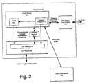
- FIG. 3 illustrates the interaction between various functional components that make up a Web router node 300.
- the method implemented in nodes to determine an optimum server for a given information object or service is referred to as "URL Routing" and an information object identifier or service identifier is referred to as a "URL".
- the node maps each URL provided by a requestor to the address of an information object repository that can optimally provide the associated information object. This mapping of URLs to addresses is accomplished by the collaboration among nodes through WILD. Accordingly, the node contacted by the requestor can return the required addresses immediately after processing the request.
- a WILD protocol module 302 uses mappings of clients (or, more generally, requestors)-to-nodes received from other nodes along with load information regarding any local servers 306 to produce a mapping table that lists the address of the server (i.e., information object repository) that is best suited to service requests from identified clients.
- the WILD protocol module 302 further uses an ALP module 304 for obtaining VON connectivity and node reachability information. It also uses ALP messages to encapsulate and deliver its own WILD messages to neighbor nodes. For further information regarding the Adaptive Link-State Protocol or ALP see, J.J. Garcia-Luna-Aceves and M. Spohn, "Scalable Link-State Internet Routing," Proc.
- ALP IEEE International Conference on Network Protocols (ICNP 98), Austin Texas, October 14-16,1998, pp. 52-61 .)
- Other routing protocols can be used instead of ALP, provided that the protocol does not create permanent or long-term loops after link cost increases or resource failures.
- the ALP module 304 reports distances to the WILD module 302, so that the WILD module 302 knows about unreachable nodes while determining the validity of different maps.
- the inter-communication between WILD module 302 and ALP module 304 may take place through the use of shared memory 314.
- ALP module 304 notifies the WILD protocol module 302 as distances to various nodes and information object repositories change.
- a node 300 receives a WILD message (i.e., a WILD message that was received encapsulated in an ALP message), it first validates the message contents, and then updates its tables based on distance. The end result is that the WILD tables at each node 300 converge to the optimum mappings.
- the WILD protocol module 302 obtains load information from its local information object repository 306. This load information is subsequently used by the WILD protocol module 302 for generating the mappings discussed above. More particularly, the WILD module 302 periodically polls the local information object repository 306 to obtain the load information. If the information object repository 306 fails, a load of infinity is reported to the WILD module 302.
- the WILD protocol module 304 also interacts with a Web router query (WRQ) module 308 in directing requestors to optimum information object repositories.
- the node 300 responds to queries from the WRQ module 308 for the nearest server, Web cache, redirector, DNS server or another node.
- a node may be contacted through the WRQ module 308 by a client or a server (or other information object repository) seeking to discover an optimum information object repository for one or more information objects distributed over the computer network. This scheme makes use of a neighbor protocol module 310.
- the VON topology can be established manually via a set of command tools or Web GUIs. That is, the present invention does not preclude a manual topology set-up. However, it is more useful to allow for dynamic configuration of the VON, especially as the size of the topology grows and the dynamic nature of the distribution cloud is taken into consideration. Additionally, static (i.e., manual) and dynamic topology control can be mixed and used together for maximum flexibility and control.
- this process of dynamic VON configuration provides that as a new node is added to the network it automatically discovers its neighbors and connects to the VON.
- the new node is provided with a configuration file containing the minimum information necessary to become part of a VON.
- the new node uses the information in its configuration file, the new node contacts a so-called "directory" server to learn about nearby nodes (called candidate neighbors below). Then, where appropriate (i.e., depending on the specified performance metrics), the new node establishes tunnels to one or more of these nearby nodes and checks to see whether, if by doing so, it has established connectivity to the VON.
- the present invention provides effective distributed algorithms to automatically discover and maintain a topology of the VON that is close to optimum.
- the topology of the VON adapts to changing network conditions, such as node or link failures or traffic provisions, to maintain optimality.
- the architecture of the VON facilitates adding and removing nodes from the VON, and adapting the VON topology accordingly.
- Links in the VON can be characterized by various metrics, such as latency, available bandwidth, loss rate, and others.
- metrics such as latency, available bandwidth, loss rate, and others.
- RTT round-trip time
- forward delay latency and the available bandwidth are the metrics used to characterize links in the VON.
- metrics such as link latency and bandwidth need to be estimated or measured periodically.
- a sender can measure round-trip latency via a probe packet that is reflected back at the destination.
- the evaluations of such metrics take into account the asymmetry of these qualities on the virtual links and provide the values bth for the forward direction and the reverse direction.
- the frequency of any probe package transmissions has to be such that the traffic overhead is minimal yet it must also provide for (i.e., allow for the capture information regarding) adaptability in the VON topology.
- probes may be sent on the order of minutes (here, it is expected that the topology changes in the VON are rather infrequent, on the order of hours, because the underlying physical links and network routing provide adaptivity to near-term changes in network conditions).
- the VON topology should use the underlying network effciently.
- a node can have up to a maximum of k max neighbors. Because each node communicates with all its neighbors to maintain several types of routing information, allowing a node to have more than k max neighbors may adversely affect and degrade the performance of the routing protocols running at the node.
- the topology of the VON For the sake of fault-tolerance, it is desirable for the topology of the VON to be k-connected, where k ⁇ 2.
- k the minimum degree of a graph needs to be "k" as a necessary condition for graph to be k-connected graph.
- the connectivity of the graph increases. This tends to reduce the diameter of the graph, which is also good. That is, the maximum number of (virtual) hops between nodes is decreased, thereby reducing the latencies between any two nodes of the VON.
- the increased connectivity of the VON topology also provides more choices for information dissemination over the VON.
- the method can be generalized to construct a k-connected graph in a distributed manner.
- its topology could include a hierarchical structure.
- the present invention could be extended to be a two-level hierarchy, where the levels reflect inter-AS and intra-AS node communication.
- a routing domain is called an autonomous system (AS).
- AS autonomous system
- BGP Border Gateway Protocol
- An example of an intra-domain routing protocol is the Open Shortest Path First (OSPF) protocol. Extending the approach described herein to a multi-level hierarchy is also possible. However, for simplicity the focus of the remaining description is on a flat topology.
- OSPF Open Shortest Path First
- the closest neighbor heuristic used in establishing the VON topology connects nodes that are close in the underlying cloud. That is, the topological structure of the VON reflects that of the underlying network. Therefore, nodes that are far according to the underlying cloud will not be neighbors. Also, in the discussion below, selecting the least-cost edges locally is a heuristic motivated by existing distributed minimum-spanning tree (MST) algorithms. Minimizing the cost of the VON corresponds to minimizing the utilization fn the network resources.
- MST distributed minimum-spanning tree
- a node can have three types of neighbors: A static neighbor is one that is established via a management console and is mandatory. A candidate neighbor is one that a node knows about but is not established as being adjacent in the VON topology. A chosen neighbor is one that is considered an actual neighbor in the VON topology. The same terms can be applied to the (tunnel) links connecting a node to its neighbors according to the neighbor type.
- the type of neighbor is determined and updated in response to the sending and receiving of the following messages, whether between nodes or between management consoles and nodes (i.e., these messges are used in the process of setting up and maintaining the VON):
- Nodes may also send queries to other nodes to learn about their connectivity. The following is a query message and response between neighbor nodes to communicate such information between one another.
- the following pseudo-code specifies the basic operations (SetCandidate, SetChosen, UnsetChosen, and RedirectNeighbor) performed at each node to initiate a change in the status of its neighbors.
- Each node maintains three sets: staticset, candidateset, and chosenset, corresponding to type of neighbors it has.
- the procedures SetCandidate and SetChosen are executed to make a neighbor candidate and chosen, respectively.
- the procedure UnsetChosen changes a chosen neighbor to a candidate neighbor.
- the procedure RedirectNeighbor redirects existing neighbors to other nodes.
- the following pseudo-code describes the steps taken by a node in response to receiving one of the above requests.
- the requests initiate a change to a neighbor's type. The process first determines whether the node has already reached its maximum permitted number of connections. If so, the request is redirected. If not, the requesting node is added as the appropriate type (in the case of a chosen or candidate request) or removed from consideration (in the case of a redirect request).
- a mechanism is needed to add new nodes into a topology and to remove them as needed.
- a new node When a new node is installed in the field, it is installed with a configuration file containing the minimum information needed to become part of a VON.
- secure remote access i.e., ssh
- a management console can be used to update the configuration file if needed.
- Removing a node (for maintenance, etc.) from a VON ends its participation in the topology control process.
- the automatic bootstrapping of a new node builds on the DNS (the Internet domain name system, see P. Mockapetris, "Domain Names - Concepts and Facilities", IETF RFC 1034, November 1987 , and P. Mockapetris, "Domain Names - Implementation and Specification", IETF RFC 1035, November 1987 ) mechanism and as such benefits from the fault-tolerance and robustness of the DNS.
- the topology of the VON can be a full mesh.
- a full mesh though is not scalable to a large number of nodes and should be applied only in a small distribution cloud.
- a node starts by setting up a link with one existing node already in the VON. This can be managed, for instance, via the management console manually. After the link is established, the new node can discover all other nodes by obtaining the topology information from the existing node that is already a member of the VON. The new node can then set up tunnels to all other nodes in the VON.
- WDNS WILD-enabled DNS
- d.isp.net an example of a directory server
- it returns (again using the standard DNS protocols and packets) a set of nodes that are "close" to the new node.
- the WDNS server uses the IP address of the new node encoded in the look up string to select the set of candidate neighbors for the new node.
- the IP address of the new node is encoded in the look up request because the standard DNS query does not carry the IP address of the originating client for the lookup request, but rather carries only the address of the local DNS server.
- the size of the set of nodes returned by the WDNS server could be one; the size of the set does not imply how many neighbors the new node will have in the VON.
- returning a larger set allows for fault-tolerance in that another candidate can be contacted if one of the nodes in the set is down or unreachable due to transient failures or delays. Returning only one value is just the simplest approach.
- a response arrives at the new node with a set of the IP addresses of candidate neighbors.
- the new node evaluates the link metric for each of the candidates. Then it establishes at least k min links by adding the "cheapest" links according to the link metric(s). If the size of the candidate set from the WDNS server is less than k min , the node builds up its candidate set from its existing neighbors.
- node A is the new node to join the VON consisting of nodes B, C, D and E.
- node B be the nearest node, and the only one returned by the WDNS server in response to a DNS look up request by node A. Then, node A will establish a (tunnel) link with node B.
- a new node performs a connectivity test.
- the connectivity test determines whether or not the new node is connected to a "core" node (i.e., has a route, through one or more neighbors, to a core node).
- a core node is any node that is on the virtual backbone of the topology.
- the virtual backbone is a set of nodes that are monitored and maintained to be up and available 24 hours a day/7 days a week via a Network Operation Center (NOC). It could consist of only one node. If there is a set of nodes on the backbone, then it is assumed that all of them are guaranteed, via network monitoring tools (e.g., the Simple Network Management Protocol (SNMP)), to be connected to each other. Otherwise, if the cores are not connected, isolated islands of nodes can be formed around each core and the overall VON topology would be disconnected.
- network monitoring tools e.g., the Simple Network Management Protocol (SNMP)
- the core nodes to use are also determined by a DNS look up, i.e., by resolving core.d.isp.net. As a convention, the core nodes could be the WDNS nodes. At a minimum, there is one entry in the core set. If there are multiple core nodes in the response, the new node will check to see if it has a route to any of them. As long as there is a route to one core node then the new node is connected to the VON topology.
- An anchor is a node that has an EGP and IGP feeds (e.g., BGP and OSPF, respectively), and is responsible for computing the mapping of client addresses or address ranges to a best match server.
- EGP and IGP feeds e.g., BGP and OSPF, respectively
- a WDNS node should therefore be connected to an anchor to allow for its computation of matching address prefixes to the best nodes.
- a topology graph represents the local knowledge of the network nodes and their interconnections, i.e., a "map.”
- TUND_Join is a pseudo-code representation of the process discssed above and describes the steps taken by a node to join the VON.
- the calls to ConnectivityTest, MinConnect, MaxConnect, and AugConnect (each presented in detail below) relate to the connectivity requirements and are described in the following paragraphs.
- nodes or links in the VON will fail and the remaining nodes may need to take action to restore lost connectivity to the VON.
- two general tasks for a node adjacent to a link or node failure to perform after the failure are:
- the links of a VON, or tunnels adapt to changes in the underlying network by virtue of adaptive routing in the underlying network.
- the VON links may follow different paths in the underlying network over time.
- a VON link functions as long as the underlying network is connected between the two ends of the link.
- VON links will fail within a finite time. Any permanent or long-lived partitions in the underlying network will result in partitioning of the VON topology. If the implementation considerations allow it, a link failure indication will be sent from the routing process to the "tund” process, since the routing process has a link failure detection mechanism. Otherwise, a "hello" protocol may be used to detect VON link failures.
- a node When a node detects a VON link failure, it will attempt to replace the failed endpoint with a subset of the neighbors of the failed endpoint. This information is gathered from its local topology graph. This is the preferred method; nevertheless, the node could, alternatively, perform a DNS look up for aabbccee.d.isp.net, where aabbccee is the IP address of the failed endpoint. In response, the requesting node would receive a set of nearby nodes to use to establish a new link. Considering the example in Figure 4 , if node B failed, then node A would try to establish links with nodes C and/or E, depending on the link metric(s) and its connectivity requirements. The neighbors of B are known from its routing advertisements to A, which A maintains in its topology graph.
- a node may fail due to any number of reasons, such as power outages, hardware or software failures, etc.
- a node failure can result in a partitioning of the VON topology, even though the underlying network is connected.
- the connectivity of a VON needs to be "rich", i.e., at least k-connected.
- ConnectivityTest When a node detects that its neighbor has failed, it executes a ConnectivityTest. In the process, a node knows whether or not it is still connected to the core of a VON. Thereafter, the node may augment its local connectivity, so that it has no "cut” neighbors by performing the AugConnect process (see below). This procedure results in a 2-connected topology in this example.
- k min and k max are configurable variables.
- a node learns about other candidates via its existing neighbors. For example, every node can query any of its neighbors (of any type) for the neighbors of the neighbor. A node can also learn about other candidates via it chosen set of neighbors. This technique of querying neighbors can be used to implement an expanding ring search to find nodes at various hops in the topology. Note, however, that a node may not know all the chosen neighbors of its chosen neighbors if only partial topology information is used in the routing protocol (e.g., ALP).
- ALP routing protocol
- a node In order to satisfy its minimum connectivity requirements, a node performs the MinConnect process (e.g., any time k min criteria is not satisfied at a node). At the same time, a node should actively stay below its maximum connectivity k max . As new neighbors acquire a node, therefore, the node should unload some of its existing neighbors. This procedure is described in MaxConnect pseudo-code below. Finally, when a node reaches its k high , it starts sending redirections to a subset of its other neighbors.
- MinConnect process e.g., any time k min criteria is not satisfied at a node.
- Each node performs the process AugConnect to establish a topology robust to failures.
- a chosen neighbor is classified as either primary or secondary.
- the AugConnect procedure augments the topology by adding a secondary chosen neighbor in case a primary chosen neighbor fails.
- node A would augment its connectivity by establishing a link with either node C or E, because if node B, which a primary chosen neighbor, fails, then the rest of the nodes become unreachable.
- a node on an on-going basis performs to a DNS look up to discover new nodes that are close to it.
- a node is added between A and B or if E become closer to A than B according to the metric, then A can update it link accordingly.
- Procedure ClosestConnect provides for this process.
- the following pseudo-code representation describes the main procedure executed at a node.
- the node When the node first boots up, it consults its configuration file as discussed above. Next, any static tunnels that have been manually configured are established. Thereafter, the node executes TUND_Join to join the VON by dynamically establishing its candidate and chosen neighbor sets. After joining the VON, the node waits for messages from other nodes or other indications of network condition changes and acts accordingly to reestablish its connectivity.
Landscapes
- Engineering & Computer Science (AREA)
- Computer Networks & Wireless Communication (AREA)
- Signal Processing (AREA)
- Software Systems (AREA)
- Theoretical Computer Science (AREA)
- General Engineering & Computer Science (AREA)
- Physics & Mathematics (AREA)
- General Physics & Mathematics (AREA)
- Computer Hardware Design (AREA)
- Environmental & Geological Engineering (AREA)
- Data Exchanges In Wide-Area Networks (AREA)
- Information Transfer Between Computers (AREA)
Claims (15)
- Verfahren, das umfasst:dynamisches Unterhalten eines virtuellen Overlay-Netzwerkes, VON, (200) über einem Netzwerkverbund (100) durch Übertragungen zwischen Knoten, die Nachrichten umfassen, die dazu ausgebildet sind, unter mehreren Knoten (200a-202h) Knotennachbarn einzurichten, wobei die Nachrichten über Tunnel innerhalb des Netzwerkverbunds geführt werden und wobei zumindest einer der Knoten (200a-202h) einen Tunnelverwaltungsprozess zum Aufbauen und Überwachen der Tunnel innerhalb des Netzwerkverbunds aufweist und wobei die Knotennachbarn einen Nachbarknotenkandidaten und/oder einen Auswahlnachbarknoten und/oder einen statischen Nachbarknoten umfassen, Empfangen von Verzeichnisanfragen von einem ersten Knoten der Knoten (200a-202h) an einem Verzeichnisknoten und hierdurch veranlasstes Zurücksenden einer oder mehrerer Adressen von nahe gelegenen Nachbarknotenkandidaten des ersten Knotens (200a-202h), die unter den mehreren Knoten (200a-202h) ausgewählt wurden,wobei der erste Knoten eine Nachbarkandidatennachricht an einen zweiten Knoten der mehreren Knoten (200a-202h) sendet, unter den nahe gelegenen Nachbarknotenkandidaten (200a-202h) des ersten Knotens (200a-202h) ausgewählt ist,Empfangen einer Bestätigungsnachricht von dem zweiten Knoten (200a-202h), um den zweiten Knoten (200a-202h) als Nachbarknotenkandidaten des ersten Knotens (200a-202h) einzurichten, wenn der zweite Knoten (200a-202h) die maximal zulässige Anzahl von Verbindungen nicht erreicht hat, undEmpfangen einer Umleitungskandidatennachricht von dem zweiten Knoten (200a-202h), um die Nachbarkandidatennachricht zur Begrenzung der Konnektivität des zweiten Knotens innerhalb des VON umzuleiten, wenn der zweite Knoten die maximal zulässige Anzahl von Verbindungen erreicht hat.
- Verfahren nach Anspruch 1, wobei, wenn der zweite Knoten (200a-202h) als Nachbarknotenkandidat des ersten Knotens (200a-202h) eingerichtet wird, zumindest eine der Nachrichten dazu verwendet wird, von dem zweiten Knoten (200a-202h) nahe gelegene Nachbarknotenkandidaten des zweiten Knotens (200a-202h) abzufragen, die unter den Knoten (200a-202h) ausgewählt wurden, wobei ein Nachbarkandidat des zweiten Knotens (200a-202h) als Nachbarknotenkandidat des ersten Knotens (200a-202h) auf Basis einer Konnektivität des Nachbarkandidaten des zweiten Knotens (200a-202h) und/oder einer oder mehrerer Verbindungskostenmetriken zwischen dem ersten Knoten (200a-202h) und dem Nachbarkandidaten des zweiten Knotens (200a-202h) eingerichtet wird.
- Verfahren nach Anspruch 1 oder 2, wobei jeder der mehreren Knoten (200a-202h) des VON über einen oder mehrere Übertragungswege mit einem oder mehreren Kernknoten des VON verbunden ist, zumindest eine der Nachrichten zur Bestimmung des einen oder der mehreren Übertragungswege zu dem einen oder den mehreren Kernknoten verwendet wird, und von den mehreren Knoten (200a-202h) jeder, der nicht mit dem einen oder den mehreren Kernknoten des VON verbunden ist, sich nicht im VON befindet.
- Verfahren nach Anspruch 1, das ferner umfasst:Senden einer Nachbarauswahlnachricht an den zweiten Knoten (200a-202h) undEmpfangen einer Bestätigungsnachricht von dem zweiten Knoten (200a-202h), um den zweiten Knoten (200a-202h) als Auswahlnachbarknoten des ersten Knotens (200a-202h) einzurichten, oder Empfangen einer Auswahlumleitungsnachricht von dem zweiten Knoten (200a-202h), um die Nachbarauswahlnachricht zur Begrenzung der Konnektivität des zweiten Knotens innerhalb des VON umzuleiten.
- Verfahren nach Anspruch 4, wobei der Nachbarknotenkandidat und/oder der Auswahlnachbarknoten auf Basis von einer oder mehreren Verbindungskostenmetriken zwischen den Knoten ausgewählt werden und die eine oder die mehreren Verbindungskostenmetriken eine Verbindungslatenz und/oder eine verfügbare Bandbreite und/oder eine Paketverlustrate umfassen, wobei die Verbindungslatenz auf Basis der Paketumlaufzeit geschätzt wird und wobei die verfügbare Bandbreite unter Verwendung einer Paketpaartechnik und/oder einer Übertragung von Datenblöcken geschätzt wird.
- Verfahren nach Anspruch 2, wobei die Verbindungskostenmetriken eine Verbindungslatenz und/oder eine verfügbare Bandbreite und/oder eine Paketverlustrate umfassen, wobei die Verbindungslatenz auf Basis der Paketumlaufzeit geschätzt wird und wobei die verfügbare Bandbreite unter Verwendung einer Paketpaartechnik und/oder einer Übertragung von Datenblöcken geschätzt wird.
- Verfahren nach Anspruch 1, wobei die Verzeichnisabfragen auf einem Domainennamensystem für den Netzwerkverbund basieren, die Knoteninformation des ersten Knotens (200a-202h) in die Verzeichnisabfragen codiert ist und die Auswahlnachbarknoten des ersten Knotens (200a-202h) aus den nahe gelegenen Nachbarknotenkandidaten des ersten Knotens (200a-202h) gewählt werden.
- Virtuelles Overlay-Netzwerk, das aufweist:mehrere Knoten (200a-202h), die zum Einrichten einer Topologie über virtuelle Verbindungen miteinander verbunden sind, wobei die Knoten dazu ausgebildet sind, verteilte Algorithmen auszuführen, um die Topologie in Reaktion auf veränderte Bedingungen bei einem darunterliegenden Netzwerkverbund durch Austausch von Übertragungen zwischen Knoten, die zum Einrichten von Knotennachbarn aus den Knoten (200a-202h) verwendet werden, dynamisch zu aktualisieren, wobei zumindest einer der Knoten (200a-202h) einen virtuellen Verbindungsverwaltungsprozess zum Aufbauen und Überwachen der virtuellen Verbindungen innerhalb des Netzwerkverbunds umfasst, die Knotennachbarn einen Nachbarknotenkandidaten und/oder einen Auswahlnachbarknoten und/oder einen statischen Nachbarknoten umfassen, und wobei ein Verzeichnisknoten dazu ausgebildet ist, von einem ersten Knoten der Knoten (200a-202h) eine Suchabfrage zu empfangen und hierdurch veranlasst eine oder mehrere Adressen nahe gelegener Nachbarknotenkandidaten aus den Knoten (200a-202h) in der Topologie zurückzusenden, und wobei die Nachrichten eine von dem ersten Knoten gesendete Nachbarkandidatennachricht zum Einrichten des zweiten Knotens der Knoten (200a-202h), der unter den nahe gelegenen Nachbarknotenkandidaten als Nachbarkandidatenknoten des ersten Knotens (200a-202h) ausgewählt wurde, eine von dem zweiten Knoten (200a-202h) an den ersten Knoten (200a-202h) gesendete Bestätigungsnachricht, falls der zweite Knoten (200a-202h) nicht seine maximal zulässige Anzahl von Verbindungen erreicht hat, und eine von dem zweiten Knoten an den ersten Knoten gesendete Umleitungskandidatennachricht umfasst, um die Nachbarkandidatennachricht an einen dritten Knoten der Knoten (200a-202h) zur Begrenzung einer Konnektivität des zweiten Knotens (200a-202h) innerhalb der Topologie umzuleiten, falls der zweite Knoten die maximale Anzahl zulässiger Verbindungen erreicht hat, und wobei der dritte Knoten (200a-202h) unter den nahe gelegenen Nachbarknotenkandidaten als Nachbarknotenkandidat des ersten Knotens (200a-202h) ausgewählt ist.
- Virtuelles Overlay-Netzwerk nach Anspruch 8, worin die veränderten Bedingungen einen oder mehrere Verbindungsausfälle und/oder einen oder mehrere Knotenausfälle umfassen.
- Virtuelles Overlay-Netzwerk nach Anspruch 8, das zum Einrichten statischer Knoten in der Topologie ferner eine Konsole zur manuellen Topologieverwaltung aufweist.
- Virtuelles Overlay-Netzwerk nach Anspruch 8, worin die verteilten Algorithmen Prozesse aufweisen, die dazu ausgebildet sind, jedem der Knoten (200a-202h) ein Evaluieren der Auswahlmöglichkeiten für Auswahlnachbarknoten aus ihren individuellen Sätzen nahe gelegener Nachbarknotenkandidaten zu ermöglichen, die verteilten Algorithmen Prozesse aufweisen, die dazu ausgebildet sind, jedem der Knoten (200a-202h) zu ermöglichen, dass er dem virtuellen Overlay-Netzwerk gerecht wird und dieses erhält, und worin die verteilten Algorithmen Prozesse aufweisen, die dazu ausgebildet sind, den Knoten ein Aktualisieren ihrer individuellen Sätze von Auswahlnachbarknoten zu ermöglichen.
- Virtuelles Overlay-Netzwerk nach Anspruch 8, worin die Knoten (200a-202h) ferner dazu ausgebildet sind, beim Einrichten des Nachbarknotenkandidaten und/oder des Auswahlnachbarknotens eine oder mehrere Verbindungsmetriken zu evaluieren, wobei die Verbindungsmetriken eine Latenz und/oder verfügbare Bandbreite und/oder Verlustrate umfassen, und wobei die Latenz unter Verwendung einer Umlaufzeit geschätzt wird, die verfügbare Bandbreite unter Verwendung einer Paketpaartechnik und/oder einer Übertragung von Daten geschätzt wird, jeder Knoten auf eine begrenzte Anzahl von Nachbarknotenkandidaten oder Auswahlnachbarknoten beschränkt ist, die geringer als alle Knoten des virtuellen Overlay-Netzwerks ist, und die Topologie des virtuellen Overlay-Netzwerks die eines darunter liegenden Netzwerkverbunds wiederspiegelt.
- Virtuelles Overlay-Netzwerk nach Anspruch 8, worin die Nachrichten umfassen:Konnektivitätstests und/oderNachbarkandidatenanfragen und/oderNachbarkandidatenbestätigungen und/oderAuswahlnachbaranfragen und/oderAuswahlnachbarbestätigungen und/oderUmleitungsanfragen und/oderUmleitungsbestätigungen und/oderNachbarsuchanfragen und/oderNachbarsuchbestätigungen.
- Virtuelles Overlay-Netzwerk nach Anspruch 13, worin jeder der Knoten (200a-202h) der Topologie über einen oder mehrere Übertragungswege mit einem oder mehreren Kernknoten der Topologie verbunden ist, wobei von den Knoten (200a-202h) jeder, der nicht mit einem oder mehreren Kernknoten der Topologie verbunden ist, sich nicht in dem virtuellen Overlay-Netzwerk befindet und wobei die Konnektivitätstests verwendet werden, um den einen oder die mehreren Übertragungswege zu dem einen oder den mehreren Kernknoten zu bestimmen.
- Verfahren nach Anspruch 1, das ferner umfasst:Bestimmen eines aus den mehreren Knoten (220a-202h) ausgewählten statischen Nachbarknotens des ersten Knotens (200a-202h), wobei der statische Nachbarknoten aus den mehreren Knoten (220a-202h) ausgewählt wird und wobei der statische Nachbarknoten unter Verwendung einer manuellen Verwaltungskonsole eingerichtet wird.
Applications Claiming Priority (5)
| Application Number | Priority Date | Filing Date | Title |
|---|---|---|---|
| US32312601P | 2001-09-10 | 2001-09-10 | |
| US32289901P | 2001-09-10 | 2001-09-10 | |
| US323126P | 2001-09-10 | ||
| US322899P | 2001-09-10 | ||
| PCT/US2002/028829 WO2003024007A1 (en) | 2001-09-10 | 2002-09-10 | System and method for information object routing in computer networks |
Publications (3)
| Publication Number | Publication Date |
|---|---|
| EP1440529A1 EP1440529A1 (de) | 2004-07-28 |
| EP1440529A4 EP1440529A4 (de) | 2011-01-19 |
| EP1440529B1 true EP1440529B1 (de) | 2016-08-24 |
Family
ID=26983668
Family Applications (3)
| Application Number | Title | Priority Date | Filing Date |
|---|---|---|---|
| EP02763625.7A Expired - Lifetime EP1433051B1 (de) | 2001-09-10 | 2002-09-10 | System und verfahren zum informationsobjekt-routing in computernetzwerken |
| EP02798206.5A Expired - Lifetime EP1440529B1 (de) | 2001-09-10 | 2002-09-10 | System und verfahren zum informationsobjekt-routing in computernetzwerken |
| EP02766274A Expired - Lifetime EP1433077B1 (de) | 2001-09-10 | 2002-09-10 | System und verfahren zum lenken von clients zu optimalen servern in computernetzwerken |
Family Applications Before (1)
| Application Number | Title | Priority Date | Filing Date |
|---|---|---|---|
| EP02763625.7A Expired - Lifetime EP1433051B1 (de) | 2001-09-10 | 2002-09-10 | System und verfahren zum informationsobjekt-routing in computernetzwerken |
Family Applications After (1)
| Application Number | Title | Priority Date | Filing Date |
|---|---|---|---|
| EP02766274A Expired - Lifetime EP1433077B1 (de) | 2001-09-10 | 2002-09-10 | System und verfahren zum lenken von clients zu optimalen servern in computernetzwerken |
Country Status (2)
| Country | Link |
|---|---|
| EP (3) | EP1433051B1 (de) |
| WO (3) | WO2003023607A1 (de) |
Cited By (2)
| Publication number | Priority date | Publication date | Assignee | Title |
|---|---|---|---|---|
| US9847930B2 (en) | 2000-03-16 | 2017-12-19 | Adara Networks, Inc. | System and method for directing clients to optimal servers in computer networks |
| WO2019055578A1 (en) * | 2017-09-12 | 2019-03-21 | Adara Networks, Inc. | PROTOCOL FOR DYNAMIC BOND STATE ROUTING |
Families Citing this family (11)
| Publication number | Priority date | Publication date | Assignee | Title |
|---|---|---|---|---|
| JP4299996B2 (ja) * | 2002-05-29 | 2009-07-22 | 株式会社日立ハイテクノロジーズ | 遠隔保守システムおよび遠隔保守方法 |
| US7512679B2 (en) * | 2003-08-29 | 2009-03-31 | International Business Machines Corporation | Apparatus and method to select a captain from a plurality of control nodes |
| US7821921B2 (en) | 2007-04-22 | 2010-10-26 | International Business Machines Corporation | Reliable and resilient end-to-end connectivity for heterogeneous networks |
| US8560604B2 (en) | 2009-10-08 | 2013-10-15 | Hola Networks Ltd. | System and method for providing faster and more efficient data communication |
| US8867403B2 (en) | 2011-08-18 | 2014-10-21 | International Business Machines Corporation | Virtual network overlays |
| US9241044B2 (en) | 2013-08-28 | 2016-01-19 | Hola Networks, Ltd. | System and method for improving internet communication by using intermediate nodes |
| WO2015196016A1 (en) * | 2014-06-19 | 2015-12-23 | Convida Wireless, Llc | Context-aware content publication and resolution |
| US11057446B2 (en) | 2015-05-14 | 2021-07-06 | Bright Data Ltd. | System and method for streaming content from multiple servers |
| LT3472717T (lt) | 2017-08-28 | 2021-01-11 | Luminati Networks Ltd. | Būdas pagerinti turinio parsisiuntimą, pasirenkant tunelinius įrenginius |
| EP4220442A1 (de) | 2019-02-25 | 2023-08-02 | Bright Data Ltd. | System und verfahren für url-abrufwiederholungsmechanismus |
| EP4383686A1 (de) | 2019-04-02 | 2024-06-12 | Bright Data Ltd. | System und verfahren zur verwaltung eines nichtdirekten url-abrufdienstes |
Family Cites Families (21)
| Publication number | Priority date | Publication date | Assignee | Title |
|---|---|---|---|---|
| US6185619B1 (en) * | 1996-12-09 | 2001-02-06 | Genuity Inc. | Method and apparatus for balancing the process load on network servers according to network and serve based policies |
| US5774668A (en) * | 1995-06-07 | 1998-06-30 | Microsoft Corporation | System for on-line service in which gateway computer uses service map which includes loading condition of servers broadcasted by application servers for load balancing |
| US6097718A (en) * | 1996-01-02 | 2000-08-01 | Cisco Technology, Inc. | Snapshot routing with route aging |
| US6400681B1 (en) * | 1996-06-20 | 2002-06-04 | Cisco Technology, Inc. | Method and system for minimizing the connection set up time in high speed packet switching networks |
| US6052718A (en) * | 1997-01-07 | 2000-04-18 | Sightpath, Inc | Replica routing |
| US6201794B1 (en) * | 1997-03-07 | 2001-03-13 | Advanced Micro Devices, Inc. | Network with efficient message routing |
| US6256675B1 (en) * | 1997-05-06 | 2001-07-03 | At&T Corp. | System and method for allocating requests for objects and managing replicas of objects on a network |
| US6006264A (en) * | 1997-08-01 | 1999-12-21 | Arrowpoint Communications, Inc. | Method and system for directing a flow between a client and a server |
| US6266706B1 (en) * | 1997-09-15 | 2001-07-24 | Effnet Group Ab | Fast routing lookup system using complete prefix tree, bit vector, and pointers in a routing table for determining where to route IP datagrams |
| US6047330A (en) * | 1998-01-20 | 2000-04-04 | Netscape Communications Corporation | Virtual router discovery system |
| US6205481B1 (en) * | 1998-03-17 | 2001-03-20 | Infolibria, Inc. | Protocol for distributing fresh content among networked cache servers |
| US6130881A (en) * | 1998-04-20 | 2000-10-10 | Sarnoff Corporation | Traffic routing in small wireless data networks |
| US6115752A (en) * | 1998-05-21 | 2000-09-05 | Sun Microsystems, Inc. | System and method for server selection for mirrored sites |
| US6377551B1 (en) * | 1998-08-17 | 2002-04-23 | Nortel Networks Limited | QoS based route determination method for communications networks |
| US6298381B1 (en) * | 1998-10-20 | 2001-10-02 | Cisco Technology, Inc. | System and method for information retrieval regarding services |
| JP2000196677A (ja) * | 1998-12-28 | 2000-07-14 | Fujitsu Ltd | ネットワ―クシステムに用いられる中継装置 |
| US6415323B1 (en) * | 1999-09-03 | 2002-07-02 | Fastforward Networks | Proximity-based redirection system for robust and scalable service-node location in an internetwork |
| US6724733B1 (en) * | 1999-11-02 | 2004-04-20 | Sun Microsystems, Inc. | Method and apparatus for determining approximate network distances using reference locations |
| US20020031131A1 (en) | 2000-02-02 | 2002-03-14 | Yechiam Yemini | Method and apparatus for the exchange of data between a dynamically addressed network and a foreign network |
| US6820133B1 (en) * | 2000-02-07 | 2004-11-16 | Netli, Inc. | System and method for high-performance delivery of web content using high-performance communications protocol between the first and second specialized intermediate nodes to optimize a measure of communications performance between the source and the destination |
| US7162539B2 (en) * | 2000-03-16 | 2007-01-09 | Adara Networks, Inc. | System and method for discovering information objects and information object repositories in computer networks |
-
2002
- 2002-09-10 WO PCT/US2002/028961 patent/WO2003023607A1/en not_active Application Discontinuation
- 2002-09-10 WO PCT/US2002/028829 patent/WO2003024007A1/en not_active Application Discontinuation
- 2002-09-10 EP EP02763625.7A patent/EP1433051B1/de not_active Expired - Lifetime
- 2002-09-10 EP EP02798206.5A patent/EP1440529B1/de not_active Expired - Lifetime
- 2002-09-10 EP EP02766274A patent/EP1433077B1/de not_active Expired - Lifetime
- 2002-09-10 WO PCT/US2002/028960 patent/WO2003023639A1/en not_active Application Discontinuation
Cited By (3)
| Publication number | Priority date | Publication date | Assignee | Title |
|---|---|---|---|---|
| US9847930B2 (en) | 2000-03-16 | 2017-12-19 | Adara Networks, Inc. | System and method for directing clients to optimal servers in computer networks |
| WO2019055578A1 (en) * | 2017-09-12 | 2019-03-21 | Adara Networks, Inc. | PROTOCOL FOR DYNAMIC BOND STATE ROUTING |
| US10554538B2 (en) | 2017-09-12 | 2020-02-04 | Adara Networks, Inc. | Dynamic link state routing protocol |
Also Published As
| Publication number | Publication date |
|---|---|
| EP1433077B1 (de) | 2013-03-06 |
| WO2003023639A1 (en) | 2003-03-20 |
| WO2003024007A1 (en) | 2003-03-20 |
| EP1433051A1 (de) | 2004-06-30 |
| EP1433077A1 (de) | 2004-06-30 |
| EP1433051A4 (de) | 2011-01-19 |
| EP1440529A4 (de) | 2011-01-19 |
| WO2003023607A1 (en) | 2003-03-20 |
| EP1433051B1 (de) | 2016-01-20 |
| EP1433077A4 (de) | 2011-01-19 |
| EP1440529A1 (de) | 2004-07-28 |
Similar Documents
| Publication | Publication Date | Title |
|---|---|---|
| Jokela et al. | LIPSIN: Line speed publish/subscribe inter-networking | |
| US6993593B2 (en) | Interdomain routing system | |
| US6856991B1 (en) | Method and apparatus for routing data to a load balanced server using MPLS packet labels | |
| EP1811724B1 (de) | Ermittlung von Schicht 2 Netzpfaden | |
| US7664876B2 (en) | System and method for directing clients to optimal servers in computer networks | |
| US7619982B2 (en) | Active probe path management | |
| US7088718B1 (en) | Server load balancing using IP option field approach to identify route to selected server | |
| US7512702B1 (en) | Method and apparatus providing highly scalable server load balancing | |
| US7047315B1 (en) | Method providing server affinity and client stickiness in a server load balancing device without TCP termination and without keeping flow states | |
| US9143431B2 (en) | Hiding a service node in a network from a network routing topology | |
| EP1440529B1 (de) | System und verfahren zum informationsobjekt-routing in computernetzwerken | |
| US20130138732A1 (en) | Access to a network of nodes distributed over a communication architecture with the aid of a topology server with multicriteria selection | |
| Bronzino et al. | NOVN: A named-object based virtual network architecture to support advanced mobile edge computing services | |
| Ramya et al. | Software defined networking based solution in load balancing for media transfer in overlay network | |
| Akter et al. | Analysis and comparative study for developing computer network in terms of routing protocols having IPv6 network using cisco packet tracer | |
| Karrakchou et al. | A survey of routing mechanisms in ICNs | |
| US11888596B2 (en) | System and method for network reliability | |
| Pavani et al. | A review on the dynamic routing protocols in TCP/IP | |
| Pelsser et al. | Scalable support of interdomain routes in a single as | |
| Masuda et al. | Splitable: Toward routing scalability through distributed bgp routing tables | |
| Saucez et al. | ISP-Driven Informed Path Selection | |
| Wang | Cartesian core routing and Cartesian border gateway design. | |
| Sehgal et al. | A generic set-formation service | |
| Lobzhanidze | Building hybrid multicast by combining IP and application layers | |
| De | OVERLAY NETWORKS |
Legal Events
| Date | Code | Title | Description |
|---|---|---|---|
| PUAI | Public reference made under article 153(3) epc to a published international application that has entered the european phase |
Free format text: ORIGINAL CODE: 0009012 |
|
| 17P | Request for examination filed |
Effective date: 20040325 |
|
| AK | Designated contracting states |
Kind code of ref document: A1 Designated state(s): AT BE BG CH CY CZ DE DK EE ES FI FR GB GR IE IT LI LU MC NL PT SE SK TR |
|
| AX | Request for extension of the european patent |
Extension state: AL LT LV MK RO SI |
|
| A4 | Supplementary search report drawn up and despatched |
Effective date: 20101221 |
|
| 17Q | First examination report despatched |
Effective date: 20120430 |
|
| REG | Reference to a national code |
Ref country code: DE Ref legal event code: R079 Ref document number: 60248296 Country of ref document: DE Free format text: PREVIOUS MAIN CLASS: H04J0001160000 Ipc: H04L0012260000 |
|
| GRAP | Despatch of communication of intention to grant a patent |
Free format text: ORIGINAL CODE: EPIDOSNIGR1 |
|
| INTG | Intention to grant announced |
Effective date: 20160226 |
|
| RIC1 | Information provided on ipc code assigned before grant |
Ipc: H04L 29/08 20060101ALI20160212BHEP Ipc: H04L 12/26 20060101AFI20160212BHEP Ipc: H04L 29/12 20060101ALI20160212BHEP Ipc: G06F 9/50 20060101ALI20160212BHEP Ipc: H04L 12/727 20130101ALI20160212BHEP Ipc: H04L 12/701 20130101ALI20160212BHEP Ipc: H04L 12/733 20130101ALI20160212BHEP |
|
| GRAS | Grant fee paid |
Free format text: ORIGINAL CODE: EPIDOSNIGR3 |
|
| GRAA | (expected) grant |
Free format text: ORIGINAL CODE: 0009210 |
|
| AK | Designated contracting states |
Kind code of ref document: B1 Designated state(s): AT BE BG CH CY CZ DE DK EE ES FI FR GB GR IE IT LI LU MC NL PT SE SK TR |
|
| RAP1 | Party data changed (applicant data changed or rights of an application transferred) |
Owner name: ADARA NETWORKS, INC. |
|
| REG | Reference to a national code |
Ref country code: GB Ref legal event code: FG4D |
|
| REG | Reference to a national code |
Ref country code: CH Ref legal event code: EP |
|
| REG | Reference to a national code |
Ref country code: AT Ref legal event code: REF Ref document number: 823931 Country of ref document: AT Kind code of ref document: T Effective date: 20160915 |
|
| REG | Reference to a national code |
Ref country code: IE Ref legal event code: FG4D |
|
| REG | Reference to a national code |
Ref country code: FR Ref legal event code: PLFP Year of fee payment: 15 |
|
| REG | Reference to a national code |
Ref country code: NL Ref legal event code: FP |
|
| REG | Reference to a national code |
Ref country code: DE Ref legal event code: R096 Ref document number: 60248296 Country of ref document: DE |
|
| REG | Reference to a national code |
Ref country code: AT Ref legal event code: MK05 Ref document number: 823931 Country of ref document: AT Kind code of ref document: T Effective date: 20160824 |
|
| PG25 | Lapsed in a contracting state [announced via postgrant information from national office to epo] |
Ref country code: FI Free format text: LAPSE BECAUSE OF FAILURE TO SUBMIT A TRANSLATION OF THE DESCRIPTION OR TO PAY THE FEE WITHIN THE PRESCRIBED TIME-LIMIT Effective date: 20160824 Ref country code: IT Free format text: LAPSE BECAUSE OF FAILURE TO SUBMIT A TRANSLATION OF THE DESCRIPTION OR TO PAY THE FEE WITHIN THE PRESCRIBED TIME-LIMIT Effective date: 20160824 |
|
| PG25 | Lapsed in a contracting state [announced via postgrant information from national office to epo] |
Ref country code: PT Free format text: LAPSE BECAUSE OF FAILURE TO SUBMIT A TRANSLATION OF THE DESCRIPTION OR TO PAY THE FEE WITHIN THE PRESCRIBED TIME-LIMIT Effective date: 20161226 Ref country code: BE Free format text: LAPSE BECAUSE OF NON-PAYMENT OF DUE FEES Effective date: 20160930 Ref country code: ES Free format text: LAPSE BECAUSE OF FAILURE TO SUBMIT A TRANSLATION OF THE DESCRIPTION OR TO PAY THE FEE WITHIN THE PRESCRIBED TIME-LIMIT Effective date: 20160824 Ref country code: SE Free format text: LAPSE BECAUSE OF FAILURE TO SUBMIT A TRANSLATION OF THE DESCRIPTION OR TO PAY THE FEE WITHIN THE PRESCRIBED TIME-LIMIT Effective date: 20160824 Ref country code: GR Free format text: LAPSE BECAUSE OF FAILURE TO SUBMIT A TRANSLATION OF THE DESCRIPTION OR TO PAY THE FEE WITHIN THE PRESCRIBED TIME-LIMIT Effective date: 20161125 Ref country code: AT Free format text: LAPSE BECAUSE OF FAILURE TO SUBMIT A TRANSLATION OF THE DESCRIPTION OR TO PAY THE FEE WITHIN THE PRESCRIBED TIME-LIMIT Effective date: 20160824 |
|
| PG25 | Lapsed in a contracting state [announced via postgrant information from national office to epo] |
Ref country code: EE Free format text: LAPSE BECAUSE OF FAILURE TO SUBMIT A TRANSLATION OF THE DESCRIPTION OR TO PAY THE FEE WITHIN THE PRESCRIBED TIME-LIMIT Effective date: 20160824 |
|
| REG | Reference to a national code |
Ref country code: CH Ref legal event code: PL |
|
| REG | Reference to a national code |
Ref country code: DE Ref legal event code: R097 Ref document number: 60248296 Country of ref document: DE |
|
| PG25 | Lapsed in a contracting state [announced via postgrant information from national office to epo] |
Ref country code: SK Free format text: LAPSE BECAUSE OF FAILURE TO SUBMIT A TRANSLATION OF THE DESCRIPTION OR TO PAY THE FEE WITHIN THE PRESCRIBED TIME-LIMIT Effective date: 20160824 Ref country code: BE Free format text: LAPSE BECAUSE OF FAILURE TO SUBMIT A TRANSLATION OF THE DESCRIPTION OR TO PAY THE FEE WITHIN THE PRESCRIBED TIME-LIMIT Effective date: 20160824 Ref country code: BG Free format text: LAPSE BECAUSE OF FAILURE TO SUBMIT A TRANSLATION OF THE DESCRIPTION OR TO PAY THE FEE WITHIN THE PRESCRIBED TIME-LIMIT Effective date: 20161124 Ref country code: CZ Free format text: LAPSE BECAUSE OF FAILURE TO SUBMIT A TRANSLATION OF THE DESCRIPTION OR TO PAY THE FEE WITHIN THE PRESCRIBED TIME-LIMIT Effective date: 20160824 Ref country code: DK Free format text: LAPSE BECAUSE OF FAILURE TO SUBMIT A TRANSLATION OF THE DESCRIPTION OR TO PAY THE FEE WITHIN THE PRESCRIBED TIME-LIMIT Effective date: 20160824 |
|
| PG25 | Lapsed in a contracting state [announced via postgrant information from national office to epo] |
Ref country code: MC Free format text: LAPSE BECAUSE OF FAILURE TO SUBMIT A TRANSLATION OF THE DESCRIPTION OR TO PAY THE FEE WITHIN THE PRESCRIBED TIME-LIMIT Effective date: 20160824 |
|
| PLBE | No opposition filed within time limit |
Free format text: ORIGINAL CODE: 0009261 |
|
| STAA | Information on the status of an ep patent application or granted ep patent |
Free format text: STATUS: NO OPPOSITION FILED WITHIN TIME LIMIT |
|
| PG25 | Lapsed in a contracting state [announced via postgrant information from national office to epo] |
Ref country code: CH Free format text: LAPSE BECAUSE OF NON-PAYMENT OF DUE FEES Effective date: 20160930 Ref country code: LI Free format text: LAPSE BECAUSE OF NON-PAYMENT OF DUE FEES Effective date: 20160930 |
|
| 26N | No opposition filed |
Effective date: 20170526 |
|
| PG25 | Lapsed in a contracting state [announced via postgrant information from national office to epo] |
Ref country code: LU Free format text: LAPSE BECAUSE OF NON-PAYMENT OF DUE FEES Effective date: 20160910 |
|
| REG | Reference to a national code |
Ref country code: FR Ref legal event code: PLFP Year of fee payment: 16 |
|
| PG25 | Lapsed in a contracting state [announced via postgrant information from national office to epo] |
Ref country code: CY Free format text: LAPSE BECAUSE OF FAILURE TO SUBMIT A TRANSLATION OF THE DESCRIPTION OR TO PAY THE FEE WITHIN THE PRESCRIBED TIME-LIMIT Effective date: 20160824 |
|
| PG25 | Lapsed in a contracting state [announced via postgrant information from national office to epo] |
Ref country code: TR Free format text: LAPSE BECAUSE OF FAILURE TO SUBMIT A TRANSLATION OF THE DESCRIPTION OR TO PAY THE FEE WITHIN THE PRESCRIBED TIME-LIMIT Effective date: 20160824 |
|
| REG | Reference to a national code |
Ref country code: FR Ref legal event code: PLFP Year of fee payment: 17 |
|
| PGFP | Annual fee paid to national office [announced via postgrant information from national office to epo] |
Ref country code: IE Payment date: 20190927 Year of fee payment: 18 Ref country code: NL Payment date: 20190926 Year of fee payment: 18 Ref country code: FR Payment date: 20190925 Year of fee payment: 18 |
|
| PGFP | Annual fee paid to national office [announced via postgrant information from national office to epo] |
Ref country code: GB Payment date: 20190927 Year of fee payment: 18 |
|
| PGFP | Annual fee paid to national office [announced via postgrant information from national office to epo] |
Ref country code: DE Payment date: 20190927 Year of fee payment: 18 |
|
| REG | Reference to a national code |
Ref country code: DE Ref legal event code: R119 Ref document number: 60248296 Country of ref document: DE |
|
| REG | Reference to a national code |
Ref country code: NL Ref legal event code: MM Effective date: 20201001 |
|
| GBPC | Gb: european patent ceased through non-payment of renewal fee |
Effective date: 20200910 |
|
| PG25 | Lapsed in a contracting state [announced via postgrant information from national office to epo] |
Ref country code: NL Free format text: LAPSE BECAUSE OF NON-PAYMENT OF DUE FEES Effective date: 20201001 |
|
| PG25 | Lapsed in a contracting state [announced via postgrant information from national office to epo] |
Ref country code: FR Free format text: LAPSE BECAUSE OF NON-PAYMENT OF DUE FEES Effective date: 20200930 Ref country code: DE Free format text: LAPSE BECAUSE OF NON-PAYMENT OF DUE FEES Effective date: 20210401 |
|
| PG25 | Lapsed in a contracting state [announced via postgrant information from national office to epo] |
Ref country code: GB Free format text: LAPSE BECAUSE OF NON-PAYMENT OF DUE FEES Effective date: 20200910 Ref country code: IE Free format text: LAPSE BECAUSE OF NON-PAYMENT OF DUE FEES Effective date: 20200910 |