EP1440252B1 - A belt for a continuously variable transmission - Google Patents
A belt for a continuously variable transmission Download PDFInfo
- Publication number
- EP1440252B1 EP1440252B1 EP02800612A EP02800612A EP1440252B1 EP 1440252 B1 EP1440252 B1 EP 1440252B1 EP 02800612 A EP02800612 A EP 02800612A EP 02800612 A EP02800612 A EP 02800612A EP 1440252 B1 EP1440252 B1 EP 1440252B1
- Authority
- EP
- European Patent Office
- Prior art keywords
- belt
- endless band
- toothing
- transmission members
- members
- Prior art date
- Legal status (The legal status is an assumption and is not a legal conclusion. Google has not performed a legal analysis and makes no representation as to the accuracy of the status listed.)
- Expired - Lifetime
Links
Images


Classifications
-
- F—MECHANICAL ENGINEERING; LIGHTING; HEATING; WEAPONS; BLASTING
- F16—ENGINEERING ELEMENTS AND UNITS; GENERAL MEASURES FOR PRODUCING AND MAINTAINING EFFECTIVE FUNCTIONING OF MACHINES OR INSTALLATIONS; THERMAL INSULATION IN GENERAL
- F16G—BELTS, CABLES, OR ROPES, PREDOMINANTLY USED FOR DRIVING PURPOSES; CHAINS; FITTINGS PREDOMINANTLY USED THEREFOR
- F16G5/00—V-belts, i.e. belts of tapered cross-section
- F16G5/16—V-belts, i.e. belts of tapered cross-section consisting of several parts
- F16G5/166—V-belts, i.e. belts of tapered cross-section consisting of several parts with non-metallic rings
Definitions
- the present invention relates to a belt for a continuously variable transmission (CVT).
- CVT continuously variable transmission
- continuously variable transmissions or variable speed drives
- belts with a substantially trapezial cross section V-belts
- V-belts which are provided with lateral friction surfaces designed to co-operate with respective sides of pulleys with trapezial or vee-shaped races.
- Variation of the transmission ratio is performed by modifying, via mechanisms of a known type, the width of the race of the pulleys and consequently the winding diameter of the belt.
- belts having a body made of elastomeric material and provided with longitudinal cord reinforcing elements designed to bestow the necessary mechanical tensile strength on the belt.
- the body made of elastomeric material is normally provided with an internal indentation and an external indentation, having the purpose of bestowing on the belt a good flexibility, thus enabling the belt to operate with reduced winding diameters, at the same time maintaining a sufficiently extended lateral surface.
- transverse stiffening elements which are set on top of respective teeth of the external indentation and internal indentation and are designed to limit the transverse compression deformations of the belt itself.
- the stiffening elements set on top of each pair of teeth set opposite to one another, i.e. the inner one and the outer one respectively, can be connected by a connection member extending through the body of the belt.
- the above-described belts in which power transmission occurs through direct contact between the elastomeric material of the body and the pulleys, are not suitable for high-power drives, such as, for instance, the ones that can be employed in variable-speed drives for motor vehicles.
- belts have been proposed for dry power drives, which comprise an endless band having an elastomeric body, provided with an internal toothing and an external toothing and a plurality of longitudinal cord inserts embedded in the body, as well as a plurality of discrete transmission members overmoulded on the endless band, so as to embed one tooth of the external toothing and one tooth of the internal toothing.
- An example of belts of this type is illustrated in EP-A-1 106 865.
- An object of the present invention is to devise an improved CVT belt which allows to increase torque transmission and belt life and is still relatively simple and unexpensive to manufacture.
- a CVT belt comprising an endless flexible band having a body made of elastomeric material and a plurality of longitudinal cord inserts embedded in said body, and a plurality of transmission members fixed along the endless band and laterally delimited by mutually inclined friction flanks for engagement with a vee-shaped race of a pulley, characterised in that each transmission member includes an inner block moulded around said endless band so as to completely surround a length of said endless band and be secured thereto, and a pair of half-shell covering members transversally fitted onto said inner block and defining said friction flanks.
- numeral 1 designates, as a whole, a belt for a continuously variable transmission (CVT).
- CVT continuously variable transmission
- the belt 1 basically comprises a closed-loop endless flexible band 2, having the purpose of transmitting the load, and a plurality of transmission members 3, anchored to the endless band 2 adjacent to one another, having a substantially vee-shaped cross section in order to co-operate by friction, by means of respective pairs of mutually inclined friction flanks 4, with a vee-shaped race 5 of a pulley P (schematically indicated with a dashed line in Figures 1 and 3).
- the endless band 2 basically comprises a toothed body 6 made of elastomeric material, for example HNBR, and a plurality of cord inserts 7, which are substantially inextensible and are embedded in the body 6 and extend longitudinally and parallel to one another along the body itself.
- the inserts 7, produced according to a conventional spiralling technique, may be made of glass or aramidic fibres, for example of the material known under the trade name Kevlar®.
- the band 2 comprises an external toothing 8, i.e., a toothing made on an outer surface 9 of the body 6.
- the toothing 8 comprises a plurality of teeth 10 alternated with recesses 11.
- the teeth 10 conveniently present a substantially semicircular or parabolic cross section, but can have any shape suitable for ensuring a stable coupling with the transmission members 3.
- the transmission members 3 each comprise an inner block 12, which is overmoulded around the endless band 2 so as to completely surround a length thereof and embed a respective tooth 10 of the endless band 2, and a friction coating 13 defining the flanks 4 that co-operate with the race 5 of the pulley.
- each transmission member 3 has a substantially vee-shaped cross section (Figure 3), and presents a central through cavity 14 engaged by, and mating in shape with, the endless band 2 ( Figure 2).
- the cavity 14 is delimited, on the side facing the inside of the belt 1, by a plane surface 15 and, on the side facing the toothing 8, presents a recess 16, the shape of which is complementary to the shape of the corresponding tooth 10.
- the friction coating 13 is made up of a pair of half-shell covering elements 20, which are fitted transversely on the inner block 12, on opposite sides of the endless band 2, so as to substantially mate with one another along a median plane M of the belt 1 (figure 3).
- the covering elements 20 are conveniently made of a plastic material having predetermined frictional properties and good resistance to wear, such as, for example, a polyamide with glass-fibre filler or a fluoropolymer of the class of materials known under the trade name of MARLON-H.
- a plastic material having predetermined frictional properties and good resistance to wear such as, for example, a polyamide with glass-fibre filler or a fluoropolymer of the class of materials known under the trade name of MARLON-H.
- An example of a material that can be used is MARLON-H82 produced by M.A.P. s.r.l.
- the covering members 20 each present a cavity 24 having a shape corresponding to half of the respective inner block 12, and comprise a pair of front walls 25, an inner base wall 26, an outer base wall 27 and a side wall 28, one outer surface of which defines a flank 4 of the transmission member 3 (figure 3).
- the front walls 25 present respective median slits 30 elongated in a direction perpendicular to the plane M and open towards the plane M, so as to enable insertion of the endless band 2.
- the edges of the slits 30 are mutually convergent towards plane M.
- the flanks 4 of the transmission members 3 conveniently present one or more grooves 31, which extend longitudinally, i.e., from the inner base wall 26 to the outer base wall 27, with the purpose of dividing the flanks 4 into one or more areas 4a, 4b of contact with the pulley (figure 4).
- each transmission member 3 presents, in a longitudinal section, a shape which is tapered towards the inside of the belt 1, which is necessary for enabling small winding diameters of the belt 1 ( Figure 1) to be obtained without interference between adjacent transmission members 3.
- the transmission members 3 are slightly tapered also towards the outside, starting from the endless band 2.
- a process for manufacturing the belt 1 is described in what follows.
- the endless band 2 is produced using known techniques employed in the manufacture of toothed belts.
- the endless band 2 is positioned in a mould (not illustrated) having a seat for the endless band 2, and a plurality of cavities, which are intersected by said seat, of a shape corresponding to that of the inner blocks 12 of the transmission members 3 of the belt 1, and which are equal in number to the blocks 12 themselves, in such a way that one tooth of the endless band 2 will be housed in each cavity of the mould.
- the plastic material which makes up the inner blocks 12 is injected into the aforesaid cavities, so as to overmould the inner blocks 12 of the transmission members on the endless band 2, so that they are spaced apart from one another.
- a respective pair of covering members 20 is inserted on each inner block 12.
- the covering members 20 of each pair of adjacent transmission members 3 are substantially in contact with one another at least in the proximity of the endless band 2.
- substantially in contact is here used both in the sense that the covering members 20 are actually in contact with one another and in the sense that a small clearance is left during assembly, of the order of some tenths of a millimetre, which means that during use there is an effective contact between the elements 20 in the proximity of the endless band 2 at least on the inner side of the belt 1 when the endless band 2 is flexed.
- the substantial contact between the transmission members 3 limits the oscillations of the blocks about an axis perpendicular to the plane M when the transmission members 3 come into contact with the pulley. As a result, any fatigue stresses on the endless band 2 are substantially limited.
- Figure 5 is a partial illustration of a belt 35 according to a different embodiment of the invention.
- the belt 35 differs from the belt 1 described above, in that the front walls 25 of each covering member 20 are substantially parallel to one another in the portion thereof that is external to the endless band 2, except for minimum rakes.
- each pair of adjacent transmission members 3 arrange themselves in contact with one another, in an area corresponding to the portion thereof that is external to the endless band 2, in the rectilinear stretches of the belt and, in particular, in the portion of the belt which disengages from the pulley.
- the oscillations of the transmission members 3 about a transverse axis are thus reduced and, consequently, also the stresses on the endless band 2.
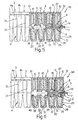
- Figure 6 shows a further embodiment of the present invention, referenced 36 as a whole.
- Belt 36 differs from belt 35 in that the endless band 2 has an outer toothing 8 and an inner toothing 37 provided on an inner surface 38 of the body 6 of the endless belt 2.
- the inner toothing 37 comprises a plurality of teeth 39 alternating with recesses 40; the teeth 39 of the inner toothing 37 are identical to respective teeth 10 of the outer toothing 8 and disposed on opposite sides with respect to the body 6.
- each transmission member 3 has a through cavity 14 which mates in shape with a portion of the endless belt 2, so that a tooth 10 of outer toothing 8 and a corresponding tooth 39 of inner toothing 37 are embedded in a respective inner block 12.
- the inner blocks 12 principally have the function of driving and structurally supporting the friction covering members 20 and therefore can be made from material having good structural properties but not necessarily optimal wear resistance and friction properties, while the covering members 20, which provide the belt-pulley interface enabling the friction torque transfer, can be made from a material specifically adapted to this purpose.
- the transmission belt of the present invention leads to a high torque transfer (for instance the belt is able to transfer torque values of over 90 Nm) and is therefore suited to a very wide range of motor vehicle and motorcycle applications.
Abstract
Description
- The present invention relates to a belt for a continuously variable transmission (CVT).
- As is known, continuously variable transmissions, or variable speed drives, employ belts with a substantially trapezial cross section (V-belts), which are provided with lateral friction surfaces designed to co-operate with respective sides of pulleys with trapezial or vee-shaped races. Variation of the transmission ratio is performed by modifying, via mechanisms of a known type, the width of the race of the pulleys and consequently the winding diameter of the belt.
- For low-power transmissions, there are currently used belts having a body made of elastomeric material and provided with longitudinal cord reinforcing elements designed to bestow the necessary mechanical tensile strength on the belt. The body made of elastomeric material is normally provided with an internal indentation and an external indentation, having the purpose of bestowing on the belt a good flexibility, thus enabling the belt to operate with reduced winding diameters, at the same time maintaining a sufficiently extended lateral surface.
- For higher-power transmissions, there is known the use of belts that are provided with transverse stiffening elements, which are set on top of respective teeth of the external indentation and internal indentation and are designed to limit the transverse compression deformations of the belt itself. The stiffening elements set on top of each pair of teeth set opposite to one another, i.e. the inner one and the outer one respectively, can be connected by a connection member extending through the body of the belt.
- The above-described belts, in which power transmission occurs through direct contact between the elastomeric material of the body and the pulleys, are not suitable for high-power drives, such as, for instance, the ones that can be employed in variable-speed drives for motor vehicles.
- For the latter applications metal belts are generally used, which, however, apart from being relatively costly and heavy, are able to operate only in oil-bath conditions and consequently present evident limits of application.
- In an attempt to overcome the above limitations of metal belts, belts have been proposed for dry power drives, which comprise an endless band having an elastomeric body, provided with an internal toothing and an external toothing and a plurality of longitudinal cord inserts embedded in the body, as well as a plurality of discrete transmission members overmoulded on the endless band, so as to embed one tooth of the external toothing and one tooth of the internal toothing. An example of belts of this type is illustrated in EP-A-1 106 865.
- An object of the present invention is to devise an improved CVT belt which allows to increase torque transmission and belt life and is still relatively simple and unexpensive to manufacture.
- The above object is achieved by the present invention, in so far as it regards a A CVT belt comprising an endless flexible band having a body made of elastomeric material and a plurality of longitudinal cord inserts embedded in said body, and a plurality of transmission members fixed along the endless band and laterally delimited by mutually inclined friction flanks for engagement with a vee-shaped race of a pulley, characterised in that each transmission member includes an inner block moulded around said endless band so as to completely surround a length of said endless band and be secured thereto, and a pair of half-shell covering members transversally fitted onto said inner block and defining said friction flanks.
- For a better understanding of the present invention, some preferred embodiments will be described hereunder with reference to the attached drawings, in which:
- Figure 1 is a partial side view of a belt made according to a first embodiment of the present invention;
- Figure 2 is a partial side view, at an enlarged scale and in partial longitudinal cross section, of the belt of Figure 1;
- Figure 3 is a cross section taken along the line III-III of Figure 2;
- Figure 4 is a partial cross section taken along the line IV-IV of Figure 3;
- With reference to Figures 1 to 4,
numeral 1 designates, as a whole, a belt for a continuously variable transmission (CVT). - The
belt 1 basically comprises a closed-loop endlessflexible band 2, having the purpose of transmitting the load, and a plurality oftransmission members 3, anchored to theendless band 2 adjacent to one another, having a substantially vee-shaped cross section in order to co-operate by friction, by means of respective pairs of mutuallyinclined friction flanks 4, with a vee-shaped race 5 of a pulley P (schematically indicated with a dashed line in Figures 1 and 3). - In particular, the
endless band 2 basically comprises atoothed body 6 made of elastomeric material, for example HNBR, and a plurality ofcord inserts 7, which are substantially inextensible and are embedded in thebody 6 and extend longitudinally and parallel to one another along the body itself. Theinserts 7, produced according to a conventional spiralling technique, may be made of glass or aramidic fibres, for example of the material known under the trade name Kevlar®. - The
band 2 comprises anexternal toothing 8, i.e., a toothing made on anouter surface 9 of thebody 6. - The
toothing 8 comprises a plurality ofteeth 10 alternated withrecesses 11. Theteeth 10 conveniently present a substantially semicircular or parabolic cross section, but can have any shape suitable for ensuring a stable coupling with thetransmission members 3. - The
transmission members 3 each comprise aninner block 12, which is overmoulded around theendless band 2 so as to completely surround a length thereof and embed arespective tooth 10 of theendless band 2, and afriction coating 13 defining theflanks 4 that co-operate with therace 5 of the pulley. - In particular, the
inner block 12 of eachtransmission member 3 has a substantially vee-shaped cross section (Figure 3), and presents a central throughcavity 14 engaged by, and mating in shape with, the endless band 2 (Figure 2). In particular, thecavity 14 is delimited, on the side facing the inside of thebelt 1, by aplane surface 15 and, on the side facing thetoothing 8, presents arecess 16, the shape of which is complementary to the shape of thecorresponding tooth 10. - The
friction coating 13 is made up of a pair of half-shell covering elements 20, which are fitted transversely on theinner block 12, on opposite sides of theendless band 2, so as to substantially mate with one another along a median plane M of the belt 1 (figure 3). - The covering
elements 20 are conveniently made of a plastic material having predetermined frictional properties and good resistance to wear, such as, for example, a polyamide with glass-fibre filler or a fluoropolymer of the class of materials known under the trade name of MARLON-H. An example of a material that can be used is MARLON-H82 produced by M.A.P. s.r.l. of San Giorgio Canavese (Turin), Italy, said material having tensile strength at brake of 48.3 MPa, elongation at brake of 350% (measured according to the standard ASTM D 638), flexural elasticity modulus of 1110 MPa at 23°C, hardness 82 shoreD (ASTM D 2240), maximum operating temperature of 150°C (ASTM D 648) and melting point of 223°C (ASTM D 3418). - The covering
members 20 each present acavity 24 having a shape corresponding to half of the respectiveinner block 12, and comprise a pair offront walls 25, aninner base wall 26, anouter base wall 27 and aside wall 28, one outer surface of which defines aflank 4 of the transmission member 3 (figure 3). - The
front walls 25 present respectivemedian slits 30 elongated in a direction perpendicular to the plane M and open towards the plane M, so as to enable insertion of theendless band 2. The edges of theslits 30 are mutually convergent towards plane M. - The
flanks 4 of thetransmission members 3 conveniently present one ormore grooves 31, which extend longitudinally, i.e., from theinner base wall 26 to theouter base wall 27, with the purpose of dividing theflanks 4 into one ormore areas - The
front walls 25 are mutually convergent starting from theendless band 2 towards the inside of thebelt 1. Consequently, eachtransmission member 3 presents, in a longitudinal section, a shape which is tapered towards the inside of thebelt 1, which is necessary for enabling small winding diameters of the belt 1 (Figure 1) to be obtained without interference betweenadjacent transmission members 3. - In the embodiment illustrated in Figures 1 to 4, for constructional reasons, the
transmission members 3 are slightly tapered also towards the outside, starting from theendless band 2. - A process for manufacturing the
belt 1 is described in what follows. - In a first step, the
endless band 2 is produced using known techniques employed in the manufacture of toothed belts. In a second step, theendless band 2 is positioned in a mould (not illustrated) having a seat for theendless band 2, and a plurality of cavities, which are intersected by said seat, of a shape corresponding to that of theinner blocks 12 of thetransmission members 3 of thebelt 1, and which are equal in number to theblocks 12 themselves, in such a way that one tooth of theendless band 2 will be housed in each cavity of the mould. In a third step, the plastic material which makes up theinner blocks 12 is injected into the aforesaid cavities, so as to overmould theinner blocks 12 of the transmission members on theendless band 2, so that they are spaced apart from one another. In a fourth step, a respective pair of coveringmembers 20 is inserted on eachinner block 12. - It should be noted that, when assembly is completed, the covering
members 20 of each pair ofadjacent transmission members 3 are substantially in contact with one another at least in the proximity of theendless band 2. The expression "substantially in contact" is here used both in the sense that the coveringmembers 20 are actually in contact with one another and in the sense that a small clearance is left during assembly, of the order of some tenths of a millimetre, which means that during use there is an effective contact between theelements 20 in the proximity of theendless band 2 at least on the inner side of thebelt 1 when theendless band 2 is flexed. - The substantial contact between the
transmission members 3 limits the oscillations of the blocks about an axis perpendicular to the plane M when thetransmission members 3 come into contact with the pulley. As a result, any fatigue stresses on theendless band 2 are substantially limited. - Figure 5 is a partial illustration of a
belt 35 according to a different embodiment of the invention. - The
belt 35 differs from thebelt 1 described above, in that thefront walls 25 of each coveringmember 20 are substantially parallel to one another in the portion thereof that is external to theendless band 2, except for minimum rakes. - In this way, the
friction coatings 13 of each pair ofadjacent transmission members 3 arrange themselves in contact with one another, in an area corresponding to the portion thereof that is external to theendless band 2, in the rectilinear stretches of the belt and, in particular, in the portion of the belt which disengages from the pulley. The oscillations of thetransmission members 3 about a transverse axis are thus reduced and, consequently, also the stresses on theendless band 2. - Figure 6 shows a further embodiment of the present invention, referenced 36 as a whole.
-
Belt 36 differs frombelt 35 in that theendless band 2 has anouter toothing 8 and aninner toothing 37 provided on an inner surface 38 of thebody 6 of theendless belt 2. - The
inner toothing 37 comprises a plurality ofteeth 39 alternating with recesses 40; theteeth 39 of theinner toothing 37 are identical torespective teeth 10 of theouter toothing 8 and disposed on opposite sides with respect to thebody 6. - The
inner block 12 of eachtransmission member 3 has a throughcavity 14 which mates in shape with a portion of theendless belt 2, so that atooth 10 ofouter toothing 8 and acorresponding tooth 39 ofinner toothing 37 are embedded in a respectiveinner block 12. - From an examination of the characteristics of the
belt 1 made according to the present invention, the advantages that the belt makes possible emerge clearly. - The
inner blocks 12 principally have the function of driving and structurally supporting thefriction covering members 20 and therefore can be made from material having good structural properties but not necessarily optimal wear resistance and friction properties, while the coveringmembers 20, which provide the belt-pulley interface enabling the friction torque transfer, can be made from a material specifically adapted to this purpose. - Research and experiments conducted by the Applicant have shown that the transmission belt of the present invention leads to a high torque transfer (for instance the belt is able to transfer torque values of over 90 Nm) and is therefore suited to a very wide range of motor vehicle and motorcycle applications.
- Further, it has been found that, also thanks to the contiguous arrangement of the
transmission members 3, a good torque transmission is obtained with relatively low loads on the teeth of thetoothing 8 and with low oscillations under load. The fatigue behaviour of thebelt 1 is, therefore, improved. - The use of a
endless band 2 with a single external toothing enables a considerable reduction in time and costs for production. - Finally, it is clear that modifications and variations can be made to the
belt 1, without thereby departing from the scope of protection defined by the ensuing claims.
Figure 6 is a side view, in partial longitudinal cross section, of a belt according to a third embodiment of the invention.
Claims (11)
- A CVT belt comprising an endless flexible band (2) having a body (6) made of elastomeric material and a plurality of longitudinal cord inserts (7) embedded in said body, and a plurality of transmission members (3) fixed along the endless band (2) and laterally delimited by mutually inclined friction flanks (4) for engagement with a vee-shaped race (5) of a pulley (P), characterised in that each transmission member (3) includes an inner block (12) moulded around said endless band (2) so as to completely surround a length of said endless band and be secured thereto, and a pair of half-shell covering members (20) transversally fitted onto said inner block (12) and defining said friction flanks (4).
- A belt as claimed in claim 1, characterised in that said covering members (20) define respective inner cavities (24) housing respective halves of the inner block (12).
- A belt as claimed in claims 1 or 2, characterised in that said covering members (20) comprise a pair of front walls (25), an inner base wall (26), an outer base wall (27) and a side wall (28), one outer surface of said side wall (28) defining a flank (4) of the respective transmission member (3).
- A belt as claimed in claim 3, characterised in that said front walls (25) present respective median slits (30) elongated in a direction perpendicular to a median plane (M) of the belt (1) and open towards said madian plane (M), so as to enable insertion of said endless band (2).
- A belt as claimed in claim 3 or 4, characterised in that said flanks (4) of the transmission members (3) have at least one longitudinal groove (31).
- A belt as claimed in any of the preceding claims, characterised in that said endless band (2) has at least one toothing (8, 37) defined by a plurality of teeth (10, 39) spaced by recesses (11, 40) and in that said inner blocks (12) of said transmission members (3) each embed at least one respective tooth (10, 39) of said toothing (8, 37).
- A belt as claimed in claim 6, characterised in that said endless band (2) has a single outer toothing (8).
- A belt as claimed in claim 6, characterised in that said endless band (2) has an outer toothing (8) and an inner toothing (37), and in that said inner blocks (12) of said transmission members (3) each embed one tooth (10) of said outer toothing (8) and one tooth (39) of said inner toothing (37).
- A belt as claimed in any of the preceding claims, characterized in that said transmission members (3) are arranged substantially in contact with one another at least in the proximity of said endless band (2).
- A belt as claimed in claim 9, characterized in that said inner blocks (12) of said transmission members (3) are spaced apart from one another, and in that said covering members (20) of each pair of adjacent transmission members (3) are arranged substantially in contact with one another at least in the proximity of said endless band (2).
- A belt as claimed in claim 10, characterized in that each pair of adjacent transmission members (3) are arranged substantially in contact with one another throughout the portion thereof extending outside said endless band (2).
Applications Claiming Priority (7)
| Application Number | Priority Date | Filing Date | Title |
|---|---|---|---|
| ITTO20010095 | 2001-10-09 | ||
| ITTO20010956 | 2001-10-09 | ||
| ITTO20010956 ITTO20010956A1 (en) | 2001-10-09 | 2001-10-09 | BELT FOR VARIABLE RATIO TRANSMISSION IN CONTINUOUS MODE - CVT. |
| ITTO20020031 | 2002-01-11 | ||
| IT2002TO000314A ITTO20020314A1 (en) | 2002-04-10 | 2002-04-10 | BELT FOR A CONTINUOUSLY VARIABLE RATIO TRANSMISSION. |
| ITTO20020314 | 2002-04-10 | ||
| PCT/EP2002/011307 WO2003031841A1 (en) | 2001-10-09 | 2002-10-09 | A belt for a continuously variable transmission |
Publications (2)
| Publication Number | Publication Date |
|---|---|
| EP1440252A1 EP1440252A1 (en) | 2004-07-28 |
| EP1440252B1 true EP1440252B1 (en) | 2005-09-14 |
Family
ID=26332886
Family Applications (1)
| Application Number | Title | Priority Date | Filing Date |
|---|---|---|---|
| EP02800612A Expired - Lifetime EP1440252B1 (en) | 2001-10-09 | 2002-10-09 | A belt for a continuously variable transmission |
Country Status (3)
| Country | Link |
|---|---|
| EP (1) | EP1440252B1 (en) |
| DE (1) | DE60206190T2 (en) |
| WO (1) | WO2003031841A1 (en) |
Families Citing this family (4)
| Publication number | Priority date | Publication date | Assignee | Title |
|---|---|---|---|---|
| ITTO20040185A1 (en) | 2004-03-19 | 2004-06-19 | Dayco Europe Srl | BELT FOR A VARIABLE TRANSMISSION WITH CONTINUITY |
| NL1027685C2 (en) * | 2004-12-08 | 2006-06-09 | Bosch Gmbh Robert | Drive belt for a transmission with bombed pulley discs. |
| JP6322073B2 (en) * | 2014-07-17 | 2018-05-09 | 三ツ星ベルト株式会社 | Power transmission belt |
| CN107816509B (en) * | 2017-11-02 | 2021-01-19 | 陈学琴 | Transmission belt of movable-plate continuously variable transmission |
Family Cites Families (10)
| Publication number | Priority date | Publication date | Assignee | Title |
|---|---|---|---|---|
| DE850539C (en) * | 1951-06-01 | 1952-09-25 | Edmund Stelzner | Link V-belt |
| JPS5722441A (en) * | 1980-07-16 | 1982-02-05 | Nissan Motor Co Ltd | Transmission v-belt |
| US4595385A (en) * | 1984-03-26 | 1986-06-17 | Dayco Corporation | Belt construction, transverse belt element therefor and method of making the same |
| JPS61103030A (en) * | 1984-10-24 | 1986-05-21 | Honda Motor Co Ltd | Transmission v-belt |
| JPS61140650A (en) * | 1984-12-13 | 1986-06-27 | Daihatsu Motor Co Ltd | Block type v-belt |
| JPS61286638A (en) * | 1985-06-14 | 1986-12-17 | Honda Motor Co Ltd | Transmission belt |
| EP0240912A3 (en) * | 1986-03-31 | 1990-05-30 | Mitsuboshi Belting Ltd. | High load transmission belt |
| JPH0510396A (en) * | 1990-11-09 | 1993-01-19 | Bando Chem Ind Ltd | High-load transmitting v-belt and manufacture thereof |
| IT1311308B1 (en) | 1999-12-10 | 2002-03-12 | Dayco Europe Srl | BELT FOR A VARIABLE RATIO TRANSMISSION IN A CONTINUOUS WAY. |
| BR0110580A (en) * | 2000-05-09 | 2003-04-01 | Gates Corp | Block type cvt belt |
-
2002
- 2002-10-09 DE DE60206190T patent/DE60206190T2/en not_active Expired - Lifetime
- 2002-10-09 EP EP02800612A patent/EP1440252B1/en not_active Expired - Lifetime
- 2002-10-09 WO PCT/EP2002/011307 patent/WO2003031841A1/en not_active Application Discontinuation
Also Published As
| Publication number | Publication date |
|---|---|
| WO2003031841A1 (en) | 2003-04-17 |
| DE60206190T2 (en) | 2006-06-08 |
| DE60206190D1 (en) | 2005-10-20 |
| EP1440252A1 (en) | 2004-07-28 |
Similar Documents
| Publication | Publication Date | Title |
|---|---|---|
| US3643518A (en) | Belt and belt drive assembly | |
| KR100500501B1 (en) | Block type cvt belt | |
| US7393487B2 (en) | Method of molding synthetic resin guide for transmission device | |
| AU2001259834A1 (en) | Block type CVT belt | |
| JPH0158376B2 (en) | ||
| KR100502763B1 (en) | Transverse reinforced cvt belt | |
| CA1217957A (en) | Belt construction for a continuously variable transmission, transverse belt element therefor and methods of making the same | |
| EP1929179B1 (en) | Toothed belt drive for use in oil and toothed belt thereof | |
| AU2001263253A1 (en) | Transverse reinforced CVT belt | |
| EP1440252B1 (en) | A belt for a continuously variable transmission | |
| EP1106865B1 (en) | Continuously-variable-ratio transmission belt | |
| US20030129350A1 (en) | Thermally conductive drive belt | |
| EP1258652A2 (en) | Belt for variable-speed drives with a continuously variable velocity ratio | |
| WO2005090823A1 (en) | Belt for a continuously variable transmission | |
| JPH0125797Y2 (en) | ||
| JPH0141967Y2 (en) | ||
| JPH0142681Y2 (en) | ||
| JPH0331870Y2 (en) | ||
| JPS61171936A (en) | Rubber v-belt | |
| JPH0118915Y2 (en) | ||
| JPS61165046A (en) | V-belt | |
| JP2009262390A (en) | Mold for manufacturing block | |
| AU2003256527A1 (en) | Belt |
Legal Events
| Date | Code | Title | Description |
|---|---|---|---|
| PUAI | Public reference made under article 153(3) epc to a published international application that has entered the european phase |
Free format text: ORIGINAL CODE: 0009012 |
|
| 17P | Request for examination filed |
Effective date: 20040505 |
|
| AK | Designated contracting states |
Kind code of ref document: A1 Designated state(s): AT BE BG CH CY CZ DE DK EE ES FI FR GB GR IE IT LI LU MC NL PT SE SK TR |
|
| AX | Request for extension of the european patent |
Extension state: AL LT LV MK RO SI |
|
| GRAP | Despatch of communication of intention to grant a patent |
Free format text: ORIGINAL CODE: EPIDOSNIGR1 |
|
| GRAS | Grant fee paid |
Free format text: ORIGINAL CODE: EPIDOSNIGR3 |
|
| GRAA | (expected) grant |
Free format text: ORIGINAL CODE: 0009210 |
|
| AK | Designated contracting states |
Kind code of ref document: B1 Designated state(s): DE FR GB IT |
|
| RAP1 | Party data changed (applicant data changed or rights of an application transferred) |
Owner name: DAYCO EUROPE S.R.L. |
|
| REG | Reference to a national code |
Ref country code: GB Ref legal event code: FG4D |
|
| REF | Corresponds to: |
Ref document number: 60206190 Country of ref document: DE Date of ref document: 20051020 Kind code of ref document: P |
|
| ET | Fr: translation filed | ||
| PLBE | No opposition filed within time limit |
Free format text: ORIGINAL CODE: 0009261 |
|
| STAA | Information on the status of an ep patent application or granted ep patent |
Free format text: STATUS: NO OPPOSITION FILED WITHIN TIME LIMIT |
|
| 26N | No opposition filed |
Effective date: 20060615 |
|
| PGFP | Annual fee paid to national office [announced via postgrant information from national office to epo] |
Ref country code: FR Payment date: 20141008 Year of fee payment: 13 Ref country code: DE Payment date: 20141007 Year of fee payment: 13 Ref country code: GB Payment date: 20141008 Year of fee payment: 13 |
|
| PGFP | Annual fee paid to national office [announced via postgrant information from national office to epo] |
Ref country code: IT Payment date: 20141022 Year of fee payment: 13 |
|
| REG | Reference to a national code |
Ref country code: DE Ref legal event code: R119 Ref document number: 60206190 Country of ref document: DE |
|
| GBPC | Gb: european patent ceased through non-payment of renewal fee |
Effective date: 20151009 |
|
| PG25 | Lapsed in a contracting state [announced via postgrant information from national office to epo] |
Ref country code: IT Free format text: LAPSE BECAUSE OF NON-PAYMENT OF DUE FEES Effective date: 20151009 Ref country code: DE Free format text: LAPSE BECAUSE OF NON-PAYMENT OF DUE FEES Effective date: 20160503 Ref country code: GB Free format text: LAPSE BECAUSE OF NON-PAYMENT OF DUE FEES Effective date: 20151009 |
|
| REG | Reference to a national code |
Ref country code: FR Ref legal event code: ST Effective date: 20160630 |
|
| PG25 | Lapsed in a contracting state [announced via postgrant information from national office to epo] |
Ref country code: FR Free format text: LAPSE BECAUSE OF NON-PAYMENT OF DUE FEES Effective date: 20151102 |