EP1439947B1 - Casting mold half and casting mold for producing contact lenses - Google Patents
Casting mold half and casting mold for producing contact lenses Download PDFInfo
- Publication number
- EP1439947B1 EP1439947B1 EP02790299A EP02790299A EP1439947B1 EP 1439947 B1 EP1439947 B1 EP 1439947B1 EP 02790299 A EP02790299 A EP 02790299A EP 02790299 A EP02790299 A EP 02790299A EP 1439947 B1 EP1439947 B1 EP 1439947B1
- Authority
- EP
- European Patent Office
- Prior art keywords
- casting mold
- insert
- mold half
- mount
- shaping surface
- Prior art date
- Legal status (The legal status is an assumption and is not a legal conclusion. Google has not performed a legal analysis and makes no representation as to the accuracy of the status listed.)
- Expired - Lifetime
Links
- 238000005266 casting Methods 0.000 title claims abstract description 145
- 238000007493 shaping process Methods 0.000 claims abstract description 49
- 239000000463 material Substances 0.000 claims abstract description 44
- 239000007858 starting material Substances 0.000 claims abstract description 38
- 238000004132 cross linking Methods 0.000 claims abstract description 16
- 239000004033 plastic Substances 0.000 claims description 8
- 229920003023 plastic Polymers 0.000 claims description 8
- 239000004926 polymethyl methacrylate Substances 0.000 claims description 8
- 229910001369 Brass Inorganic materials 0.000 claims description 7
- 239000010951 brass Substances 0.000 claims description 7
- 229920003229 poly(methyl methacrylate) Polymers 0.000 claims description 7
- 238000003754 machining Methods 0.000 claims description 6
- 229920012287 polyphenylene sulfone Polymers 0.000 claims description 4
- 238000011144 upstream manufacturing Methods 0.000 claims description 3
- 238000005520 cutting process Methods 0.000 claims description 2
- VYPSYNLAJGMNEJ-UHFFFAOYSA-N Silicium dioxide Chemical compound O=[Si]=O VYPSYNLAJGMNEJ-UHFFFAOYSA-N 0.000 description 15
- 238000000034 method Methods 0.000 description 14
- 238000004519 manufacturing process Methods 0.000 description 13
- VYZAMTAEIAYCRO-UHFFFAOYSA-N Chromium Chemical compound [Cr] VYZAMTAEIAYCRO-UHFFFAOYSA-N 0.000 description 11
- 229910052804 chromium Inorganic materials 0.000 description 11
- 239000011651 chromium Substances 0.000 description 11
- 230000008569 process Effects 0.000 description 9
- 238000000465 moulding Methods 0.000 description 7
- 125000006850 spacer group Chemical group 0.000 description 6
- 230000035699 permeability Effects 0.000 description 5
- 229920000491 Polyphenylsulfone Polymers 0.000 description 4
- 229930040373 Paraformaldehyde Natural products 0.000 description 3
- XAGFODPZIPBFFR-UHFFFAOYSA-N aluminium Chemical compound [Al] XAGFODPZIPBFFR-UHFFFAOYSA-N 0.000 description 3
- 229910052782 aluminium Inorganic materials 0.000 description 3
- 238000011161 development Methods 0.000 description 3
- 238000007689 inspection Methods 0.000 description 3
- 238000001459 lithography Methods 0.000 description 3
- 229920006324 polyoxymethylene Polymers 0.000 description 3
- 238000007789 sealing Methods 0.000 description 3
- 239000004696 Poly ether ether ketone Substances 0.000 description 2
- 229910000831 Steel Inorganic materials 0.000 description 2
- JUPQTSLXMOCDHR-UHFFFAOYSA-N benzene-1,4-diol;bis(4-fluorophenyl)methanone Chemical compound OC1=CC=C(O)C=C1.C1=CC(F)=CC=C1C(=O)C1=CC=C(F)C=C1 JUPQTSLXMOCDHR-UHFFFAOYSA-N 0.000 description 2
- 238000004891 communication Methods 0.000 description 2
- 230000000295 complement effect Effects 0.000 description 2
- 230000000694 effects Effects 0.000 description 2
- 230000006872 improvement Effects 0.000 description 2
- 238000001746 injection moulding Methods 0.000 description 2
- 239000007788 liquid Substances 0.000 description 2
- 238000000206 photolithography Methods 0.000 description 2
- 229920002530 polyetherether ketone Polymers 0.000 description 2
- -1 polypropylene Polymers 0.000 description 2
- 239000010959 steel Substances 0.000 description 2
- XLYOFNOQVPJJNP-UHFFFAOYSA-N water Substances O XLYOFNOQVPJJNP-UHFFFAOYSA-N 0.000 description 2
- 241000789082 Diachrysia chrysitis Species 0.000 description 1
- 229920005482 Oroglas® Polymers 0.000 description 1
- 239000004743 Polypropylene Substances 0.000 description 1
- 239000012876 carrier material Substances 0.000 description 1
- 238000010276 construction Methods 0.000 description 1
- 239000000356 contaminant Substances 0.000 description 1
- 238000011109 contamination Methods 0.000 description 1
- 230000007547 defect Effects 0.000 description 1
- 230000001419 dependent effect Effects 0.000 description 1
- 238000006073 displacement reaction Methods 0.000 description 1
- 238000000605 extraction Methods 0.000 description 1
- 230000009969 flowable effect Effects 0.000 description 1
- 239000011521 glass Substances 0.000 description 1
- 230000001771 impaired effect Effects 0.000 description 1
- 235000015252 lyoner Nutrition 0.000 description 1
- 230000000873 masking effect Effects 0.000 description 1
- 238000005259 measurement Methods 0.000 description 1
- 239000000203 mixture Substances 0.000 description 1
- 230000003287 optical effect Effects 0.000 description 1
- 230000002093 peripheral effect Effects 0.000 description 1
- 229920000642 polymer Polymers 0.000 description 1
- 238000006116 polymerization reaction Methods 0.000 description 1
- 229920001155 polypropylene Polymers 0.000 description 1
- 239000010453 quartz Substances 0.000 description 1
- 230000005855 radiation Effects 0.000 description 1
- 230000009467 reduction Effects 0.000 description 1
- 230000000717 retained effect Effects 0.000 description 1
- 238000000926 separation method Methods 0.000 description 1
- 239000002904 solvent Substances 0.000 description 1
- 230000001954 sterilising effect Effects 0.000 description 1
- 238000004659 sterilization and disinfection Methods 0.000 description 1
- 239000000126 substance Substances 0.000 description 1
- 238000012360 testing method Methods 0.000 description 1
- 230000007704 transition Effects 0.000 description 1
Images




Classifications
-
- B—PERFORMING OPERATIONS; TRANSPORTING
- B29—WORKING OF PLASTICS; WORKING OF SUBSTANCES IN A PLASTIC STATE IN GENERAL
- B29D—PRODUCING PARTICULAR ARTICLES FROM PLASTICS OR FROM SUBSTANCES IN A PLASTIC STATE
- B29D11/00—Producing optical elements, e.g. lenses or prisms
- B29D11/00009—Production of simple or compound lenses
- B29D11/00038—Production of contact lenses
- B29D11/00125—Auxiliary operations, e.g. removing oxygen from the mould, conveying moulds from a storage to the production line in an inert atmosphere
-
- B—PERFORMING OPERATIONS; TRANSPORTING
- B29—WORKING OF PLASTICS; WORKING OF SUBSTANCES IN A PLASTIC STATE IN GENERAL
- B29D—PRODUCING PARTICULAR ARTICLES FROM PLASTICS OR FROM SUBSTANCES IN A PLASTIC STATE
- B29D11/00—Producing optical elements, e.g. lenses or prisms
- B29D11/00009—Production of simple or compound lenses
- B29D11/00038—Production of contact lenses
-
- B—PERFORMING OPERATIONS; TRANSPORTING
- B29—WORKING OF PLASTICS; WORKING OF SUBSTANCES IN A PLASTIC STATE IN GENERAL
- B29D—PRODUCING PARTICULAR ARTICLES FROM PLASTICS OR FROM SUBSTANCES IN A PLASTIC STATE
- B29D11/00—Producing optical elements, e.g. lenses or prisms
- B29D11/00009—Production of simple or compound lenses
- B29D11/00038—Production of contact lenses
- B29D11/00057—Production of contact lenses characterised by the shape or surface condition of the edge, e.g. flashless, burrless, smooth
-
- B—PERFORMING OPERATIONS; TRANSPORTING
- B29—WORKING OF PLASTICS; WORKING OF SUBSTANCES IN A PLASTIC STATE IN GENERAL
- B29D—PRODUCING PARTICULAR ARTICLES FROM PLASTICS OR FROM SUBSTANCES IN A PLASTIC STATE
- B29D11/00—Producing optical elements, e.g. lenses or prisms
- B29D11/00009—Production of simple or compound lenses
- B29D11/00038—Production of contact lenses
- B29D11/00125—Auxiliary operations, e.g. removing oxygen from the mould, conveying moulds from a storage to the production line in an inert atmosphere
- B29D11/00134—Curing of the contact lens material
-
- Y—GENERAL TAGGING OF NEW TECHNOLOGICAL DEVELOPMENTS; GENERAL TAGGING OF CROSS-SECTIONAL TECHNOLOGIES SPANNING OVER SEVERAL SECTIONS OF THE IPC; TECHNICAL SUBJECTS COVERED BY FORMER USPC CROSS-REFERENCE ART COLLECTIONS [XRACs] AND DIGESTS
- Y10—TECHNICAL SUBJECTS COVERED BY FORMER USPC
- Y10S—TECHNICAL SUBJECTS COVERED BY FORMER USPC CROSS-REFERENCE ART COLLECTIONS [XRACs] AND DIGESTS
- Y10S425/00—Plastic article or earthenware shaping or treating: apparatus
- Y10S425/808—Lens mold
Definitions
- the invention relates to a casting mold half and a casting mold for producing contact lenses.
- the contact lenses are preferably produced by what is known as the mold or full-mold process.
- the lenses are produced in their final shape between two casting mold halves (molds), so that neither subsequent machining of the surfaces of the lenses nor machining of the edge is required. Mold processes are described, for example, in WO-A-87/04390 or in the EP-A 0 367 513.
- the geometry of the contact lens to be produced is established by the cavity defined between the casting mold halves.
- the edge of the contact lens is likewise formed by the casting mold, usually comprising two casting mold halves.
- the geometry of the edge is established by the contour of the two casting mold halves in the region in which they contact each other.
- a specific amount of the flowable starting material is introduced into the female casting mold half. After that, the mold is closed by placing on the male casting mold half. It is customary for a little more starting material than is necessary to be fed in, so that, when the casting mold is closed, the excess amount is displaced into an overflow space adjoining the cavity on the outside.
- the subsequent polymerization or crosslinkage of the starting material takes place by irradiation with UV light or by heat exposure or some other non-thermal method. In this case, both the starting material in the cavity and excess material in the overflow space are cured. To obtain flawless separation of the contact lens from the excess material, good sealing and displacement of the excess material must be achieved in the contact zone of the two casting mold halves. Only in this way flawless contact lens edges can be obtained.
- the contact lenses produced in this way are flexible, soft moldings with a water content of typically over 60% by weight. After its completion, the contact lens also undergoes verifying test measurements, is then packed and subjected to high-temperature sterilization (for example at 121°C) in an autoclave.
- high-temperature sterilization for example at 121°C
- Plastics such as polypropylene for example, are used with preference as materials for these casting molds or casting mold halves.
- the molds are produced by injection molding and used only once.
- One reason for this is that the casting molds or casting mold halves are sometimes contaminated by the excess material, damaged when the contact lenses are detached or deformed irreversibly in partial regions when the casting mold is sealed.
- the casting molds are used only once, since a certain deformation of the casting molds in their edge region cannot be ruled out with certainty.
- US-A-5,508,317 describes a novel contact lens material which represents an important improvement of the polymerizable starting materials for the production of contact lenses.
- the patent discloses a water-soluble composition of a prepolymer, which is filled into the cavity and subsequently crosslinked photochemically.
- the prepolymer carries a plurality of crosslinkable groups, and the crosslinkage process is distinguished by high speed, so that a finished contact lens of optical quality can be produced within a few seconds, without subsequent extraction or secondary finishing steps being required.
- Contact lenses can be produced at considerably lower costs by the improved starting material presented in the patent, so that as a result the production of disposable contact lenses is made possible.
- EP-A-0 637 490 describes a method by which a further improvement of the production process for contact lenses can be achieved with the prepolymer described in US-A-5,508,317.
- the starting material prepolymer
- the starting material is in this case filled into a casting mold comprising two casting mold halves, the two casting mold halves not being in contact with each other, but instead a thin, annular gap being arranged between them.
- the gap is in communication with the cavity, so that excess starting material (prepolymer) can flow away into the gap.
- the crosslinkage of the starting material takes place by irradiation, in particular with UV light, a delimitation of the irradiation to the mold cavity being achieved for example by a chromium mask. Consequently, only the material located in the cavity is crosslinked, so that a high degree of reproducibility of the edge shapes of the contact lens can be achieved without completely closing the two casting mold halves.
- quartz glass molds are used in practice, since, on account of the water-soluble starting material, they can be quickly and effectively cleaned of the uncrosslinked prepolymer and other residues and dried after a contact lens has been produced. Furthermore, quartz glass is distinguished by very good UV permeability and is very hard and resistant. In addition, quartz is an established substance as a carrier material for chromium masks in UV lithography.
- EP-A-0 941 829 use is made of the principles explained above for the efficient production of contact lenses.
- a molding tool which has two tool halves is proposed in EP-A-0 941 829, which corresponds to the preamble of claim 1.
- Each tool half has a number of receptacles, into which respectively complementary casting mold halves are inserted, to be precise for example female casting mold halves into one tool half and the associated male casting mold halves into the other tool half.
- the casting mold halves are clamped with high precision in the receptacles and, when the tool halves are closed, the tool halves and consequently the casting mold halves are positioned precisely in relation to one another.
- Such a casting mold half clamped into a receptacle in each case comprises a mount, for example made of brass, which has a channel and a wall surrounding this channel.
- a mount for example made of brass
- an insert which is accommodated by the mount and has a shaping surface for the shaping of the front or rear surface of the contact lens to be produced.
- the insert is produced, for example, from the quartz glass mentioned above, the previously already mentioned chromium mask being applied for example to the insert of the male casting mold half.
- the chromium mask applied to the quartz glass has a layer thickness of about 0.3 ⁇ m and is preferably produced by processes known in photolithography or UV lithography.
- the chromium masks produced in this way often do not have the service lives required for an automatic production process and exhibit damage at an early time due to detachment of the chromium layer. Since, however, the inserts made of quartz glass with the chromium layer applied to them are very expensive to produce, the service lives of the casting molds should be very long to allow a cost-effective process to be ensured.
- the object of the present invention is therefore to improve a casting mold or casting mold half of the generic type in such a way that the same edge quality of the contact lenses as with the previous casting molds or casting mold halves can be achieved.
- the technical production-related expenditure for the casting molds or casting mold halves is to be reduced, and consequently further cost reductions are to be made possible for the production of contact lenses.
- a casting mold half with a mount and with an insert (a placed-on attachment would also be possible), which is arranged at one end of the mount and can be connected to the mount and which has a shaping surface for the shaping of the front or rear surface of the contact lens to be produced.
- the insert consists in the region of the shaping surface of a material which is permeable to the energy crosslinking the starting material of the contact lens.
- the casting mold half comprises a mask made of a material impermeable to the energy crosslinking the starting material, for spatially delimiting this energy.
- the mask itself comprises a separate surround made of a material impermeable to the energy crosslinking the starting material of the contact lens, which surrounds the edge region of the shaping surface of the insert.
- the masking properties of the surround should happen to be no longer retained completely, for example on account of a material defect, it is merely necessary to exchange the surround - which after all is a separate part - and not for instance, as previously, to replace the entire quartz glass mold with the chromium mask applied to it, which is costly because applying the chromium mask to the quartz glass is a relatively complex technical process.
- a separate surround can also be adapted in respect of its dimensions to the part of the insert with the shaping surface (for example by turning the inside diameter of the surround on a lathe), if the dimensions of the surround and of the part of the insert with the shaping surface should happen not quite to match one another optimally.
- the surround is therefore produced from a material which can be machined.
- the insert is likewise produced in the region of the shaping surface from a material which can be machined, and the material of the surround is formed in terms of its machining properties in such a way that it can be machined by the same cutting tool. Consequently, it is possible to rework both the shaping part and the surround (for example to remove a certain amount by turning on a lathe) from time to time, for example whenever deviations occur in the dimensional accuracy (geometry) of the contact lenses.
- the remachined casting mold half (for example the remachined male casting mold half) can be reused together with the other (for example non-remachined female) casting mold half without further measures, as explained in more detail further below.
- the setting-up operation when setting up the molding tool in this case remains the same as in the case of a non-remachined casting mold half, as explained further below.
- a separate diaphragm is arranged within the mount, near the insert with the shaping surface, to be precise upstream of the insert in the direction of the path of the energy.
- the diaphragm consists of a material which is impermeable to the energy crosslinking the starting material.
- the diaphragm has the effect that the energy is already delimited shortly before reaching the shaping part of the insert, and, for example in the case of UV light as the crosslinking energy, at most a slightly diverging UV light beam can pass through the diaphragm. Should the UV light beam nevertheless happen to diverge slightly, the UV light is delimited by the surround which surrounds the part of the insert with the shaping surface definitively at the desired location to the desired extent, i.e. in particular to the diameter of the contact lens.
- the diaphragm is produced from a plastic, in particular an injection-moldable plastic, such as for example polyphenylene sulfone (PPSU, black).
- a plastic in particular an injection-moldable plastic, such as for example polyphenylene sulfone (PPSU, black).
- PPSU polyphenylene sulfone
- Such a material can be processed well, for example using the injection-molding technique or using the Ihating technique, and, for example when UV light is used as the energy which crosslinks the starting material for the contact lenses, has the required impermeability to the UV light.
- the diaphragm is preferably an insert part, which, when considered in the direction of the path of the energy, is arranged directly adjacent to the insert, so that the insert rests on the diaphragm.
- the insert part - the diaphragm - may in this case initially be pressed into the mount. Subsequently, that surface of the diaphragm (that is of the insert part) on which the insert or placed-on attachment comes to lie may be lathed or milled flat, for example, to be precise in particular to a level which corresponds to the level of a bearing surface of the mount surrounding the bearing surface of the diaphragm (of the insert part). The insert then rests both on the bearing surface of the diaphragm (that is of the insert part) and on the bearing surface of the mount, which then of course both lie at the same level.
- the inside diameter of the diaphragm is smaller than the inside diameter of the surround which surrounds the edge region of the shaping surface of the insert. Downstream of the diaphragm, when considered in the path of the UV light, the UV light beam may still have a certain divergence, until it impinges on the starting material for the contact lenses through the region with the shaping surface in the insert.
- the inside diameter of the diaphragm is therefore chosen to be smaller than the inside diameter of the surround, in order that, even taking into account a certain divergence of the light beam, as far as possible no UV light impinges on the starting material outside the desired region.
- the surround itself which of course - like the annular insert part also - is produced from a material impermeable to the UV light (to the crosslinking energy), delimits the light beam once again, to be precise directly at the location where the UV light impinges on the starting material for the contact lenses.
- that part of the insert on which the region with the shaping surface is provided is also produced from plastic. This allows parts with shaping surfaces which can be produced at low cost to be used.
- a polymethyl methacrylate which is adequately permeable to UV light as the crosslinking energy, may be used as the material for the part of the insert with the shaping surface.
- the surround consists for example of brass.
- a closure which is permeable to the energy crosslinking the starting material is provided at that end of the mount which is facing away from the insert.
- One purpose of such a closure is to avoid contaminants in the interior of the mount, which may have disruptive effects on the impingement of the starting material with UV light. If the closure is also adequately transparent to visible light, an initial inspection of the contact lens for inclusions (for example bubbles) is also possible while it is still in the mold, as still to be explained.
- a casting mold according to the invention for producing contact lenses comprises a male casting mold half and a female casting mold half, which have a shaping surface, respectively forming the rear and front surfaces of the contact lens, and which in the closed state define between them a cavity which substantially defines the shape of the contact lens.
- At least one of the casting mold halves, preferably the male casting mold half, is formed according to one of the exemplary embodiments described above.
- the casting mold according to the prior art shown in Fig. 1 is designed for the production of contact lenses from a liquid starting material which can be polymerized or crosslinked by UV radiation. It comprises a casting mold 1 and an energy source 2a, here a UV light source, and also means 2b for directing the energy provided by the energy source 2a onto the mold in the form of a substantially parallel beam 3. It goes without saying that the energy source 2a and the means 2b can also be combined to form a single unit.
- the casting mold 1 comprises two casting mold halves 11 and 12, which each have a curved shaping surface 13 and 14, respectively, which together define a cavity 15, which for its part in turn determines the shape of the contact lens to be produced.
- the shaping surface 13 of the casting mold half 11 that is the upper half in the drawing, known as the "male” casting mold half, is convex and determines the rear surface of the contact lens with the edge region of the same adjoining it.
- the shaping surface 14 of the other casting mold half 12 which is correspondingly referred to as the "female” casting mold half, is of a concave form and determines the front surface of the contact lens to be produced, likewise with the edge region of the same adjoining it.
- the cavity 15 is not closed off completely and in a sealed manner, but in the exemplary embodiment shown is open all around in the region of its peripheral edge, defining the edge of the contact lens to be produced, and is in communication with a relatively narrow annular gap 16.
- the annular gap 16 is delimited or formed by a planar mold wall 17 on the male casting mold half 11 and a planar mold wall 18 on the female casting mold half 12.
- spacing means are provided on the female mold half 12, for example in the form of a plurality of spacing bolts 19a and 19b, which act together with a collar or flange 20 of the male casting mold half 11 and keep the two casting mold halves at such a distance that said annular gap 16 is produced.
- the casting mold is able to be opened and closed in the customary way, for example by means of a closing unit only indicated here by the arrow symbol 1a.
- the adjustment of the spacing of the two casting mold halves 11, 12 to compensate for shrinkage may also take place by means of this external closing unit, for example.
- the male casting mold half 11 is produced, for example, from quartz glass and is reusable.
- the mask 21 is a thin chromium layer, which is applied to the quartz glass by processes known for example from photolithography or UV lithography.
- Fig. 2 shows the configuration of the casting mold 1 in the transitional region between the cavity 15 and the annular channel 16 in an enlarged representation.
- the cavity 15 has here, in the sense of an example, a shape which corresponds to the typical edge geometry of what is known as a soft contact lens CL.
- the edge of the cavity, and consequently of the lens is formed here by two wall areas 22 and 23 at right angles to one another, which are respectively formed on the male casting mold half and the female casting mold half.
- the width and height of these two wall areas and of the edge regions of the contact lens defined by them are denoted by X and Y, respectively.
- the edge of the lens may also be rounded off.
- the cylindrical wall area 23 of the female mold half 12 does not reach quite up to the planar wall area 22 or the wall area 17 of the male mold half 11 seamlessly adjoining it, but is less high by the amount ⁇ y, so that the annular gap 16 is formed or remains free between the wall area 17 and the wall area 18 of the two mold halves.
- the mask 21 provided on the wall area 17 of the male casting mold half 11 reaches horizontally right up to the extension 23a of the wall area of the female casting mold half 12.
- the UV light effecting the crosslinkage in the form of a parallel beam 3 is incident perpendicularly to the wall area 22 or 17 or parallel to the cylindrical wall area 23
- the space located perpendicularly below the mask 21 is occluded and only the starting material located within the cavity 15, that is within the imaginary extension of the wall 23a, is crosslinked, and a cleanly finished, burr-free lens edge which does not require mechanical secondary finishing is created.
- any still adhering uncrosslinked material is flushed away by means of a suitable solvent, which, depending on the material, may well be water.
- FIG. 3 A detail of a tool half of a molding tool according to the prior art, in which use is made of the principles explained above, can be seen in Fig. 3. It reveals a female casting mold half 4 which is accommodated in a receptacle of the tool half and comprises a mount 40 in which there is provided an insert 41 which has a shaping surface 410, here for shaping the front surface of a contact lens.
- the mount 40 is clamped with great precision in the receptacle with the aid of clamping means.
- the chromium mask described above is applied to the insert, which consists of quartz glass.
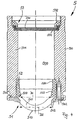
- FIG. 4 An exemplary embodiment of a casting mold half according to the invention in the form of a male casting mold half 5 is then represented in a longitudinal section in Fig. 4. It reveals a mount 50, which consists for example of brass, and which has a channel 500 and also a wall 501 surrounding this channel. Fig. 4 also reveals an insert 51, which is arranged at one end of the mount 50 and is fastened on the mount 50 by means of screws 502.
- the insert 51 comprises a region with a shaping surface 510, which is formed here on a separate part 511, which is preferably produced from plastic, in particular from polymethyl methacrylate (PMMA). However, it may also be produced from glass, in particular from quartz glass.
- the separate part 511 with the shaping surface 510 is enclosed in an annular surround 512, which consists for example of brass and extends around the edge region of the shaping surface 510, that is around the separate part 511.
- a diaphragm 52 Arranged inside the mount 50, directly adjoining the insert 51, is a diaphragm 52 formed as a separate annular insert part, to be precise upstream of the insert 51 when considered in the direction of the light path of the UV light.
- the diaphragm 52 is produced from a material which is impermeable to UV light, in particular from an injection-moldable plastic, such as for example polyphenylene sulfone (PPSU, black).
- PPSU polyphenylene sulfone
- the insert 51 is inserted into the mount 50 and connected to the mount 50 by means of three screws 502 (see screw holes 502a in Fig. 5).
- the insert 51 in this case rests both on the bearing surface 503 of the mount 50 and on the surface 520 of the diaphragm 52.
- the diaphragm 52 consequently not only brings about the delimitation of the UV light, but also improves the mechanical stability of the bearing for the insert 51.
- the exemplary embodiment of the diaphragm 52 represented here firstly has a cylindrical portion 521, which is adjoined in the direction of the insert 51 by a slightly conical portion 522.
- This slightly conical portion 522 has in particular the function of reflecting UV light possibly reflected on it into the region of the shaping surface 510, and not for instance in a direction outside this region, which is also the reason why only a slight cone is provided.
- the inside diameter D1 of the diaphragm 52 at the end of the cone facing the insert 51 is somewhat smaller than the inside diameter D2 of the surround 512.
- the surround 512 spatially delimits the UV light definitively to the region of the shaping surface 510, which establishes the geometrical shape of the rear surface of the contact lens, to be precise directly at the location at which the UV light impinges on the starting material of the contact lens.
- a small divergence of the UV light beam after passing through the diaphragm 52 is consequently delimited by the surround 512 once again directly at the location at which it impinges on the starting material, so that the starting material is impinged with UV light only in the region of the shaping surface 510.
- a closure 53 is provided for the channel 500.
- the closure 53 here comprises a disk 530, for example made of quartz glass, which is permeable to UV light, a sealing O-ring 531, and also a hold-down device 532 with an external thread, which can be screwed into a corresponding internal thread in the mount 50, so that the channel 500 is closed in a sealed manner and no contamination can penetrate.
- the quartz glass is not only suitable as a material for the disk 530, because of its UV permeability, but it also makes possible in particular (because of its permeability to visible light) an initial inspection of the contact lens for inclusions (for example bubbles) while the casting mold is still closed, that is through the disk 530.
- Fig. 6 reveals an exemplary embodiment of a casting mold 7 according to the invention, as it is represented during setting-up, in particular during the setting-up of a molding tool (see also Fig. 7, still to be explained).
- the male casting mold half 5a in Fig. 6 is formed in a way very similar to the male casting mold half 5 explained above on the basis of Fig. 4.
- a female casting mold half 6 which is of a similar construction in principle to the male casting mold half.
- the female casting mold half 6 likewise comprises a mount 60, in which there is accommodated an insert 61 which has a shaping surface 610, which establishes the shape of the front surface of the contact lens to be produced.
- the female casting mold half 6 also has a closure 63 for the channel 600, with a disk 630, for example of quartz glass, which closes the channel 600 with the aid of a sealing O-ring 631 and with the aid of a hold-down device 632.
- the diaphragm 52a of the male casting mold half 5a of the casting mold 7, formed as an annular insert part, is formed slightly differently in Fig. 6 than in the exemplary embodiment of the male casting mold half 5 in Fig. 4, but has the same function.
- the insert 51a of the casting mold half 5a is also differently formed to the extent that the inner surface of the insert 51a does not run approximately parallel in the same way as the shaping (outer) surface of the insert 51a, as is the case in the exemplary embodiment of the casting mold half 5 in Fig. 4. Rather, in the exemplary embodiment of the casting mold half 5a according to Fig. 6 it is the case that the inner surface of the insert 51a is of a flat form.
- both described variants are possible; which variant is to be preferred depends on the respective materials chosen for the inserts 51 and 51a, on the UV permeability and on the requirements demanded of the mechanical stability of the insert, etc.
- Fig. 6 also reveals a spacer 8, which is formed here as a ring and is arranged between the two casting mold halves 5a and 6 during the setting-up of the tool 9 and plays an important part during the setting-up.
- the spacer 8 is a part produced with high precision which has a very low tolerance and ensures that the two casting mold halves 5a and 6 are at a precisely defined distance from each other. In this state, the respective male casting mold half 5 or 5a and the respective female casting mold half 6 is clamped with great precision in the receptacle of the respective tool half 90 and 91 of the tool 9 (see Fig. 3 and Fig. 7).
- the tool 9 represented in Fig. 7 must be closed.
- the tool 9 can be opened again and the spacers 8 can be removed, because then the casting mold halves 5 or 5a and 6 are clamped in the respective tool half 90 and 91 in such a way that they are very precisely at the desired distance from each other when the tool 9 is closed, because the casting mold halves 5 or 5a and 6 have of course been clamped in the respective tool half 90 or 91 precisely at this distance from each other (spacers 8) beforehand with the tool 9 closed during the setting-up of the tool 9.
- the cavity formed between the two mold halves 5 or 5a and 6, which defines the shape of the contact lens is slightly open at the edge, that is to say there is an annular gap (see explanation further above), through which any extra starting material can flow into the cavity.
- the tool 9 can be closed after starting material has been dispensed into the female casting mold halves 6 or into the insert 61 with the tool 9 open. Since it is customary for a little more starting material than is necessary to be fed in, excess material is displaced through the annular gap, but any extra material may also flow through the annular gap back into the cavity.
- the tool half 91 in which the male casting mold halves 5 and 5a are clamped is swung shut by the tool half 91 being pivoted about the joint 92.
- the pivoting takes place with the aid of a movement guide 93 known per se, the two tool halves 90, 91 being held together in the closed state by a latching lever 94.
- a movement guide 93 known per se
- the two tool halves 90, 91 being held together in the closed state by a latching lever 94.
- contact surfaces 95 are provided on the mutually facing upper sides of the tool halves 90 and 91 .
- a precise alignment of the two tool halves 90, 91 during closing, and consequently a precise alignment of the casting mold halves 5 or 5a and 6 in relation to one another, is achieved with the aid of positioning bolts 96 and corresponding positioning bushes 97, the positioning bolts 96 being provided on the one tool half 91 and the positioning bushes 97 being provided on the other tool half 90, and the positioning bolts 96 entering into the positioning bushes 97 when the tool is closed.
- the male casting mold half 5a has to be reworked, because for example the contact lens produced with it has a dimensional inaccuracy of the contact lens rear surface, the entire "end" face of the male casting mold half 5a facing the female casting mold half 6 (insert together with surround and outer mount) can be lathed until it again has the desired preset geometry with dimensional accuracy over the entire "end" face.
- diaphragm materials for the diaphragm are, in particular, the already mentioned polyphenylene sulfone PPSU, black, from Ensinger GmbH & Co., Technische Kunststoffe, Rudolf-Diesel-Strasse 8, D-71154 Nurfingen, and also POM (polyoxymethylene) from the same company, and similarly for example burnished brass or blackened aluminum.
- PPSU polyphenylene sulfone
- POM polyoxymethylene
- the surrounds are as thin as desired at the transition to the edge region of the shaping surface, so that the materials used for the surround also have to be sufficiently impermeable to the UV light that the high quality of the edge of the contact lens cannot be impaired by stray UV light which impinges on the starting material outside the desired region and deviating from the direction of incidenee of the UV light.
Landscapes
- Engineering & Computer Science (AREA)
- Health & Medical Sciences (AREA)
- Manufacturing & Machinery (AREA)
- Ophthalmology & Optometry (AREA)
- Mechanical Engineering (AREA)
- Moulds For Moulding Plastics Or The Like (AREA)
- Casting Or Compression Moulding Of Plastics Or The Like (AREA)
- Eyeglasses (AREA)
Abstract
Description
- The invention relates to a casting mold half and a casting mold for producing contact lenses.
- In automatic contact lens production processes, in particular for the production of contact lenses which are to be produced cost-effectively in large numbers, the contact lenses are preferably produced by what is known as the mold or full-mold process. In these processes, the lenses are produced in their final shape between two casting mold halves (molds), so that neither subsequent machining of the surfaces of the lenses nor machining of the edge is required. Mold processes are described, for example, in WO-A-87/04390 or in the EP-A 0 367 513.
- In these known mold processes, the geometry of the contact lens to be produced is established by the cavity defined between the casting mold halves. The edge of the contact lens is likewise formed by the casting mold, usually comprising two casting mold halves.
The geometry of the edge is established by the contour of the two casting mold halves in the region in which they contact each other. - To produce a contact lens, firstly a specific amount of the flowable starting material is introduced into the female casting mold half. After that, the mold is closed by placing on the male casting mold half. It is customary for a little more starting material than is necessary to be fed in, so that, when the casting mold is closed, the excess amount is displaced into an overflow space adjoining the cavity on the outside. The subsequent polymerization or crosslinkage of the starting material takes place by irradiation with UV light or by heat exposure or some other non-thermal method. In this case, both the starting material in the cavity and excess material in the overflow space are cured. To obtain flawless separation of the contact lens from the excess material, good sealing and displacement of the excess material must be achieved in the contact zone of the two casting mold halves. Only in this way flawless contact lens edges can be obtained.
- The contact lenses produced in this way are flexible, soft moldings with a water content of typically over 60% by weight. After its completion, the contact lens also undergoes verifying test measurements, is then packed and subjected to high-temperature sterilization (for example at 121°C) in an autoclave.
- Plastics, such as polypropylene for example, are used with preference as materials for these casting molds or casting mold halves. The molds are produced by injection molding and used only once. One reason for this is that the casting molds or casting mold halves are sometimes contaminated by the excess material, damaged when the contact lenses are detached or deformed irreversibly in partial regions when the casting mold is sealed. In particular because of the requirements demanded of the quality of the contact lens edge, the casting molds are used only once, since a certain deformation of the casting molds in their edge region cannot be ruled out with certainty.
- US-A-5,508,317 describes a novel contact lens material which represents an important improvement of the polymerizable starting materials for the production of contact lenses. The patent discloses a water-soluble composition of a prepolymer, which is filled into the cavity and subsequently crosslinked photochemically. The prepolymer carries a plurality of crosslinkable groups, and the crosslinkage process is distinguished by high speed, so that a finished contact lens of optical quality can be produced within a few seconds, without subsequent extraction or secondary finishing steps being required. Contact lenses can be produced at considerably lower costs by the improved starting material presented in the patent, so that as a result the production of disposable contact lenses is made possible.
- EP-A-0 637 490 describes a method by which a further improvement of the production process for contact lenses can be achieved with the prepolymer described in US-A-5,508,317. The starting material (prepolymer) is in this case filled into a casting mold comprising two casting mold halves, the two casting mold halves not being in contact with each other, but instead a thin, annular gap being arranged between them. The gap is in communication with the cavity, so that excess starting material (prepolymer) can flow away into the gap. The crosslinkage of the starting material takes place by irradiation, in particular with UV light, a delimitation of the irradiation to the mold cavity being achieved for example by a chromium mask. Consequently, only the material located in the cavity is crosslinked, so that a high degree of reproducibility of the edge shapes of the contact lens can be achieved without completely closing the two casting mold halves.
- In this method, reusable quartz glass molds are used in practice, since, on account of the water-soluble starting material, they can be quickly and effectively cleaned of the uncrosslinked prepolymer and other residues and dried after a contact lens has been produced. Furthermore, quartz glass is distinguished by very good UV permeability and is very hard and resistant. In addition, quartz is an established substance as a carrier material for chromium masks in UV lithography.
- In EP-A-0 941 829, use is made of the principles explained above for the efficient production of contact lenses. For this purpose, a molding tool which has two tool halves is proposed in EP-A-0 941 829, which corresponds to the preamble of
claim 1. Each tool half has a number of receptacles, into which respectively complementary casting mold halves are inserted, to be precise for example female casting mold halves into one tool half and the associated male casting mold halves into the other tool half. The casting mold halves are clamped with high precision in the receptacles and, when the tool halves are closed, the tool halves and consequently the casting mold halves are positioned precisely in relation to one another. - Such a casting mold half clamped into a receptacle in each case comprises a mount, for example made of brass, which has a channel and a wall surrounding this channel.
Provided at one end of the mount is an insert, which is accommodated by the mount and has a shaping surface for the shaping of the front or rear surface of the contact lens to be produced. The insert is produced, for example, from the quartz glass mentioned above, the previously already mentioned chromium mask being applied for example to the insert of the male casting mold half. - The chromium mask applied to the quartz glass has a layer thickness of about 0.3 µm and is preferably produced by processes known in photolithography or UV lithography.
However, it is found that the chromium masks produced in this way often do not have the service lives required for an automatic production process and exhibit damage at an early time due to detachment of the chromium layer. Since, however, the inserts made of quartz glass with the chromium layer applied to them are very expensive to produce, the service lives of the casting molds should be very long to allow a cost-effective process to be ensured. - The object of the present invention is therefore to improve a casting mold or casting mold half of the generic type in such a way that the same edge quality of the contact lenses as with the previous casting molds or casting mold halves can be achieved. At the same time, however, the technical production-related expenditure for the casting molds or casting mold halves is to be reduced, and consequently further cost reductions are to be made possible for the production of contact lenses.
- This object is achieved by a casting mold half according to the invention or a casting mold according to the invention as defined by the features of the respective independent patent claim. Further advantageous embodiments of the casting mold half or the casting mold emerge from the features of the dependent patent claims.
- The object is achieved in particular by a casting mold half with a mount and with an insert (a placed-on attachment would also be possible), which is arranged at one end of the mount and can be connected to the mount and which has a shaping surface for the shaping of the front or rear surface of the contact lens to be produced. The insert consists in the region of the shaping surface of a material which is permeable to the energy crosslinking the starting material of the contact lens. Finally, the casting mold half comprises a mask made of a material impermeable to the energy crosslinking the starting material, for spatially delimiting this energy. The mask itself comprises a separate surround made of a material impermeable to the energy crosslinking the starting material of the contact lens, which surrounds the edge region of the shaping surface of the insert.
- If, for whatever reason, the masking properties of the surround should happen to be no longer retained completely, for example on account of a material defect, it is merely necessary to exchange the surround - which after all is a separate part - and not for instance, as previously, to replace the entire quartz glass mold with the chromium mask applied to it, which is costly because applying the chromium mask to the quartz glass is a relatively complex technical process.
- A separate surround can also be adapted in respect of its dimensions to the part of the insert with the shaping surface (for example by turning the inside diameter of the surround on a lathe), if the dimensions of the surround and of the part of the insert with the shaping surface should happen not quite to match one another optimally. In an advantageous exemplary embodiment of the casting mold half according to the invention, the surround is therefore produced from a material which can be machined.
- In a development of this variant, the insert is likewise produced in the region of the shaping surface from a material which can be machined, and the material of the surround is formed in terms of its machining properties in such a way that it can be machined by the same cutting tool. Consequently, it is possible to rework both the shaping part and the surround (for example to remove a certain amount by turning on a lathe) from time to time, for example whenever deviations occur in the dimensional accuracy (geometry) of the contact lenses. In such a case, the remachined casting mold half (for example the remachined male casting mold half) can be reused together with the other (for example non-remachined female) casting mold half without further measures, as explained in more detail further below. The setting-up operation when setting up the molding tool in this case remains the same as in the case of a non-remachined casting mold half, as explained further below.
- In a further exemplary embodiment of the casting mold half according to the invention, a separate diaphragm is arranged within the mount, near the insert with the shaping surface, to be precise upstream of the insert in the direction of the path of the energy. The diaphragm consists of a material which is impermeable to the energy crosslinking the starting material. The diaphragm has the effect that the energy is already delimited shortly before reaching the shaping part of the insert, and, for example in the case of UV light as the crosslinking energy, at most a slightly diverging UV light beam can pass through the diaphragm. Should the UV light beam nevertheless happen to diverge slightly, the UV light is delimited by the surround which surrounds the part of the insert with the shaping surface definitively at the desired location to the desired extent, i.e. in particular to the diameter of the contact lens.
- In a development of this exemplary embodiment, the diaphragm is produced from a plastic, in particular an injection-moldable plastic, such as for example polyphenylene sulfone (PPSU, black). Such a material can be processed well, for example using the injection-molding technique or using the Ihating technique, and, for example when UV light is used as the energy which crosslinks the starting material for the contact lenses, has the required impermeability to the UV light.
- The diaphragm is preferably an insert part, which, when considered in the direction of the path of the energy, is arranged directly adjacent to the insert, so that the insert rests on the diaphragm. The insert part - the diaphragm - may in this case initially be pressed into the mount. Subsequently, that surface of the diaphragm (that is of the insert part) on which the insert or placed-on attachment comes to lie may be lathed or milled flat, for example, to be precise in particular to a level which corresponds to the level of a bearing surface of the mount surrounding the bearing surface of the diaphragm (of the insert part). The insert then rests both on the bearing surface of the diaphragm (that is of the insert part) and on the bearing surface of the mount, which then of course both lie at the same level.
- In a development of the exemplary embodiment of the casting mold half with diaphragm, the inside diameter of the diaphragm is smaller than the inside diameter of the surround which surrounds the edge region of the shaping surface of the insert. Downstream of the diaphragm, when considered in the path of the UV light, the UV light beam may still have a certain divergence, until it impinges on the starting material for the contact lenses through the region with the shaping surface in the insert. The inside diameter of the diaphragm is therefore chosen to be smaller than the inside diameter of the surround, in order that, even taking into account a certain divergence of the light beam, as far as possible no UV light impinges on the starting material outside the desired region. The surround itself, which of course - like the annular insert part also - is produced from a material impermeable to the UV light (to the crosslinking energy), delimits the light beam once again, to be precise directly at the location where the UV light impinges on the starting material for the contact lenses.
- In a further advantageous exemplary embodiment of the casting mold half according to the invention, that part of the insert on which the region with the shaping surface is provided is also produced from plastic. This allows parts with shaping surfaces which can be produced at low cost to be used.
- For example, a polymethyl methacrylate (PMMA), which is adequately permeable to UV light as the crosslinking energy, may be used as the material for the part of the insert with the shaping surface. The surround consists for example of brass. These materials are advantageous to this extent, because they are already known for their suitability in the production of contact lenses and because they also have to a certain extent similar properties with regard to machining, so that the same tool can be used for the machining both of the part with the shaping surface and of the surround.
- In a further exemplary embodiment, a closure which is permeable to the energy crosslinking the starting material is provided at that end of the mount which is facing away from the insert. One purpose of such a closure is to avoid contaminants in the interior of the mount, which may have disruptive effects on the impingement of the starting material with UV light. If the closure is also adequately transparent to visible light, an initial inspection of the contact lens for inclusions (for example bubbles) is also possible while it is still in the mold, as still to be explained.
- A casting mold according to the invention for producing contact lenses comprises a male casting mold half and a female casting mold half, which have a shaping surface, respectively forming the rear and front surfaces of the contact lens, and which in the closed state define between them a cavity which substantially defines the shape of the contact lens. At least one of the casting mold halves, preferably the male casting mold half, is formed according to one of the exemplary embodiments described above.
- Further advantageous refinements emerge from the exemplary embodiments described below with the aid of the drawing, in which:
- Fig. 1
- shows a schematic representation of an embodiment of a casting mold known in the prior art;
- Fig. 2
- shows the detail designated in Fig. 1 by II in a greatly enlarged representation
- Fig. 3
- shows a detail from a molding tool for the efficient production of contact lenses according to the prior art, with an exemplary embodiment of a female casting mold half,
- Fig. 4
- shows a section through an exemplary embodiment of a male casting mold half according to the invention,
- Fig. 5
- shows a plan view of the casting mold half according to Fig. 4,
- Fig. 6
- shows a section through an exemplary embodiment of a casting mold according to the invention, with a male casting mold half and a female casting mold half, and
- Fig. 7
- shows a molding tool with two tool halves, a plurality of male or female casting mold halves being respectively arranged in each tool half.
- The casting mold according to the prior art shown in Fig. 1 is designed for the production of contact lenses from a liquid starting material which can be polymerized or crosslinked by UV radiation. It comprises a casting
mold 1 and anenergy source 2a, here a UV light source, and also means 2b for directing the energy provided by theenergy source 2a onto the mold in the form of a substantiallyparallel beam 3. It goes without saying that theenergy source 2a and themeans 2b can also be combined to form a single unit. - The casting
mold 1 comprises two castingmold halves curved shaping surface cavity 15, which for its part in turn determines the shape of the contact lens to be produced. The shapingsurface 13 of the castingmold half 11 that is the upper half in the drawing, known as the "male" casting mold half, is convex and determines the rear surface of the contact lens with the edge region of the same adjoining it. Conversely, the shapingsurface 14 of the othercasting mold half 12, which is correspondingly referred to as the "female" casting mold half, is of a concave form and determines the front surface of the contact lens to be produced, likewise with the edge region of the same adjoining it. - The
cavity 15 is not closed off completely and in a sealed manner, but in the exemplary embodiment shown is open all around in the region of its peripheral edge, defining the edge of the contact lens to be produced, and is in communication with a relatively narrowannular gap 16. Theannular gap 16 is delimited or formed by aplanar mold wall 17 on the male castingmold half 11 and aplanar mold wall 18 on the femalecasting mold half 12. To prevent complete closing of the mold, spacing means are provided on thefemale mold half 12, for example in the form of a plurality of spacingbolts flange 20 of the male castingmold half 11 and keep the two casting mold halves at such a distance that saidannular gap 16 is produced. The casting mold is able to be opened and closed in the customary way, for example by means of a closing unit only indicated here by the arrow symbol 1a. The adjustment of the spacing of the two castingmold halves - A
mask 21, which is impermeable to the UV light (or at least very poorly permeable in comparison with the permeability of the of the material for the casting mold or casting mold half), is provided on themold wall 17 in the region of theannular gap 16, extends right up to thecavity 15 and, with the exception of the same, shields from the irradiated energy all the remaining parts, hollow spaces or surfaces of the castingmold 1 which are in contact or could come into contact with the starting material, which here is liquid, uncrosslinked and possibly constitutes excess material. - In practice, the male casting
mold half 11 is produced, for example, from quartz glass and is reusable. Themask 21 is a thin chromium layer, which is applied to the quartz glass by processes known for example from photolithography or UV lithography. - Fig. 2 shows the configuration of the casting
mold 1 in the transitional region between thecavity 15 and theannular channel 16 in an enlarged representation. Thecavity 15 has here, in the sense of an example, a shape which corresponds to the typical edge geometry of what is known as a soft contact lens CL. The edge of the cavity, and consequently of the lens, is formed here by two wall areas 22 and 23 at right angles to one another, which are respectively formed on the male casting mold half and the female casting mold half. The width and height of these two wall areas and of the edge regions of the contact lens defined by them are denoted by X and Y, respectively. In practice, the edge of the lens may also be rounded off. As can be clearly seen, the cylindrical wall area 23 of thefemale mold half 12 does not reach quite up to the planar wall area 22 or thewall area 17 of themale mold half 11 seamlessly adjoining it, but is less high by the amount Δy, so that theannular gap 16 is formed or remains free between thewall area 17 and thewall area 18 of the two mold halves. - The
mask 21 provided on thewall area 17 of the male castingmold half 11 reaches horizontally right up to theextension 23a of the wall area of the femalecasting mold half 12. When the UV light effecting the crosslinkage in the form of aparallel beam 3 is incident perpendicularly to thewall area 22 or 17 or parallel to the cylindrical wall area 23, the space located perpendicularly below themask 21 is occluded and only the starting material located within thecavity 15, that is within the imaginary extension of thewall 23a, is crosslinked, and a cleanly finished, burr-free lens edge which does not require mechanical secondary finishing is created. After the contact lens produced in this way has been removed from the mold, any still adhering uncrosslinked material is flushed away by means of a suitable solvent, which, depending on the material, may well be water. - A detail of a tool half of a molding tool according to the prior art, in which use is made of the principles explained above, can be seen in Fig. 3. It reveals a female
casting mold half 4 which is accommodated in a receptacle of the tool half and comprises a mount 40 in which there is provided aninsert 41 which has a shapingsurface 410, here for shaping the front surface of a contact lens. The mount 40 is clamped with great precision in the receptacle with the aid of clamping means. In the case of the associated male casting mold half, the chromium mask described above is applied to the insert, which consists of quartz glass. - An exemplary embodiment of a casting mold half according to the invention in the form of a male
casting mold half 5 is then represented in a longitudinal section in Fig. 4. It reveals amount 50, which consists for example of brass, and which has achannel 500 and also awall 501 surrounding this channel. Fig. 4 also reveals aninsert 51, which is arranged at one end of themount 50 and is fastened on themount 50 by means ofscrews 502. - The
insert 51 comprises a region with a shapingsurface 510, which is formed here on aseparate part 511, which is preferably produced from plastic, in particular from polymethyl methacrylate (PMMA). However, it may also be produced from glass, in particular from quartz glass. Theseparate part 511 with the shapingsurface 510 is enclosed in anannular surround 512, which consists for example of brass and extends around the edge region of the shapingsurface 510, that is around theseparate part 511. - Arranged inside the
mount 50, directly adjoining theinsert 51, is adiaphragm 52 formed as a separate annular insert part, to be precise upstream of theinsert 51 when considered in the direction of the light path of the UV light. Thediaphragm 52 is produced from a material which is impermeable to UV light, in particular from an injection-moldable plastic, such as for example polyphenylene sulfone (PPSU, black). In the production of such acasting mold half 5, thediaphragm 52 formed as an insert part is pressed into themount 50 and subsequently the surface 520 of thediaphragm 52 adjoining theinsert 51 is lathed flat to the same level as the bearingsurface 503 of themount 50. Subsequently, theinsert 51 is inserted into themount 50 and connected to themount 50 by means of three screws 502 (seescrew holes 502a in Fig. 5). Theinsert 51 in this case rests both on thebearing surface 503 of themount 50 and on the surface 520 of thediaphragm 52. Thediaphragm 52 consequently not only brings about the delimitation of the UV light, but also improves the mechanical stability of the bearing for theinsert 51. - The exemplary embodiment of the
diaphragm 52 represented here firstly has acylindrical portion 521, which is adjoined in the direction of theinsert 51 by a slightlyconical portion 522. This slightlyconical portion 522 has in particular the function of reflecting UV light possibly reflected on it into the region of the shapingsurface 510, and not for instance in a direction outside this region, which is also the reason why only a slight cone is provided. The inside diameter D1 of thediaphragm 52 at the end of the cone facing theinsert 51 is somewhat smaller than the inside diameter D2 of thesurround 512. Thesurround 512 spatially delimits the UV light definitively to the region of the shapingsurface 510, which establishes the geometrical shape of the rear surface of the contact lens, to be precise directly at the location at which the UV light impinges on the starting material of the contact lens. A small divergence of the UV light beam after passing through thediaphragm 52 is consequently delimited by thesurround 512 once again directly at the location at which it impinges on the starting material, so that the starting material is impinged with UV light only in the region of the shapingsurface 510. - At the other end of the
mount 50, that is at that end which is facing away from theinsert 51, aclosure 53 is provided for thechannel 500. Theclosure 53 here comprises adisk 530, for example made of quartz glass, which is permeable to UV light, a sealing O-ring 531, and also a hold-downdevice 532 with an external thread, which can be screwed into a corresponding internal thread in themount 50, so that thechannel 500 is closed in a sealed manner and no contamination can penetrate. The quartz glass is not only suitable as a material for thedisk 530, because of its UV permeability, but it also makes possible in particular (because of its permeability to visible light) an initial inspection of the contact lens for inclusions (for example bubbles) while the casting mold is still closed, that is through thedisk 530. - Fig. 6 reveals an exemplary embodiment of a casting
mold 7 according to the invention, as it is represented during setting-up, in particular during the setting-up of a molding tool (see also Fig. 7, still to be explained). The malecasting mold half 5a in Fig. 6 is formed in a way very similar to the male castingmold half 5 explained above on the basis of Fig. 4. - Additionally provided is a female
casting mold half 6, which is of a similar construction in principle to the male casting mold half. In particular, the femalecasting mold half 6 likewise comprises amount 60, in which there is accommodated aninsert 61 which has a shapingsurface 610, which establishes the shape of the front surface of the contact lens to be produced. The femalecasting mold half 6 also has aclosure 63 for thechannel 600, with adisk 630, for example of quartz glass, which closes thechannel 600 with the aid of a sealing O-ring 631 and with the aid of a hold-downdevice 632. In the case of such acasting mold 7, an initial inspection of the contact lens for inclusions (for example bubbles) in particular is still possible while the castingmold 7 is closed, as is directly evident since the light path through both castingmold halves - The
diaphragm 52a of the male castingmold half 5a of the castingmold 7, formed as an annular insert part, is formed slightly differently in Fig. 6 than in the exemplary embodiment of the male castingmold half 5 in Fig. 4, but has the same function. What is more, theinsert 51a of the castingmold half 5a is also differently formed to the extent that the inner surface of theinsert 51a does not run approximately parallel in the same way as the shaping (outer) surface of theinsert 51a, as is the case in the exemplary embodiment of the castingmold half 5 in Fig. 4. Rather, in the exemplary embodiment of the castingmold half 5a according to Fig. 6 it is the case that the inner surface of theinsert 51a is of a flat form. In principle, both described variants are possible; which variant is to be preferred depends on the respective materials chosen for theinserts - Fig. 6 also reveals a
spacer 8, which is formed here as a ring and is arranged between the two castingmold halves tool 9 and plays an important part during the setting-up. Thespacer 8 is a part produced with high precision which has a very low tolerance and ensures that the two castingmold halves mold half mold half 6 is clamped with great precision in the receptacle of therespective tool half - For this purpose, the
tool 9 represented in Fig. 7 must be closed. After the various castingmold halves tool 9 can be opened again and thespacers 8 can be removed, because then the castingmold halves respective tool half tool 9 is closed, because the castingmold halves respective tool half tool 9 closed during the setting-up of thetool 9. In the closed state of thetool 9, the cavity formed between the twomold halves - Once the casting
mold halves tool halves spacers 8 have been removed, thetool 9 can be closed after starting material has been dispensed into the femalecasting mold halves 6 or into theinsert 61 with thetool 9 open. Since it is customary for a little more starting material than is necessary to be fed in, excess material is displaced through the annular gap, but any extra material may also flow through the annular gap back into the cavity. When thetool 9 is closed, thetool half 91 in which the male castingmold halves tool half 91 being pivoted about the joint 92. The pivoting takes place with the aid of amovement guide 93 known per se, the twotool halves lever 94. Provided on the mutually facing upper sides of the tool halves 90 and 91 are defined contact surfaces 95 (here, four on eachtool half tool 9 is closed. A precise alignment of the twotool halves mold halves bolts 96 andcorresponding positioning bushes 97, the positioningbolts 96 being provided on the onetool half 91 and thepositioning bushes 97 being provided on theother tool half 90, and thepositioning bolts 96 entering into thepositioning bushes 97 when the tool is closed. - In principle, the precise alignment of the casting mold halves in relation to one another can also take place in some other way; numerous possibilities for this are known from the prior art. The above description of the precise positioning of tool halves in which individual casting mold halves are clamped with high precision represents only one of many possible ways in which such an alignment of complementary casting mold halves in relation to one another can be performed.
- If, for example, the male casting
mold half 5a has to be reworked, because for example the contact lens produced with it has a dimensional inaccuracy of the contact lens rear surface, the entire "end" face of the male castingmold half 5a facing the female casting mold half 6 (insert together with surround and outer mount) can be lathed until it again has the desired preset geometry with dimensional accuracy over the entire "end" face. The setting-up operation during the setting-up of thetool 9 remains unchanged, as described above, because both the "end" face of the surround around the edge region of the shaping surface and the corresponding "end" face of the surround arranged around the latter have of course been lathed by the same amount to the same level and thespacer 8 rests on these two "end" faces during the setting-up. The remaining "end" faces are also turned to their associated preset geometry, so that altogether in such a remachining operation the castingmold half 5a is shortened somewhat in its overall length (to be precise by the amount of the turned material), but the overall "end" face is returned to its preset geometry. - Coming into consideration as materials for the inserts permeable to UV light that are used for the casting mold halves are, in particular, the materials PMMA GS 2458 from Röhm GmbH Chemische Fabrik, Kirchenallee, D-64293 Darmstadt, Oroglas VS UVT glass-clear from Polymerland Kunststoff GmbH, Industriestrasse 28a, D-68519 Viernheim, Lucryl G77 from BASF Aktiengesellschaft, D-67056 Ludwigshafen, Zeonex from Nippon Zeon Co., Ltd, Furakawa Sogo Building 2-6-1 Marunochi Chioda-ku, Tokyo 100, Japan, and also Tobas from Ticona GmbH, Lyoner Str. 38, D-60528 Frankfurt/Main.
- Coming into consideration as materials for the diaphragm are, in particular, the already mentioned polyphenylene sulfone PPSU, black, from Ensinger GmbH & Co., Technische Kunststoffe, Rudolf-Diesel-
Strasse 8, D-71154 Nurfingen, and also POM (polyoxymethylene) from the same company, and similarly for example burnished brass or blackened aluminum. - Apart from the brass already mentioned, coming into consideration for the surround are in principle also aluminum, steel, PPSU black, PEEK black, POM black, and also PMMA black, it having to be ensured that, depending on the direction in which the light is proceeding, the surrounds are as thin as desired at the transition to the edge region of the shaping surface, so that the materials used for the surround also have to be sufficiently impermeable to the UV light that the high quality of the edge of the contact lens cannot be impaired by stray UV light which impinges on the starting material outside the desired region and deviating from the direction of incidenee of the UV light.
- Finally, apart from the brass material already cited, coming into consideration for the mount are also aluminum, steel or PEEK.
Claims (11)
- A casting mold half (5,5a) for producing contact lenses, with a mount (50) and with an insert (51, 51a), which is arranged at one end of the mount (50) and can be connected to the mount (50) and which has a shaping surface (510) for the shaping of the front or rear surface of the contact lens to be produced, the insert (51, 51a) consisting in the region of the shaping surface (510) of a material which is permeable to the energy crosslinking the starting material of the contact lens, and finally with a mask made of a material impermeable to the energy crosslinking the starting material, for spatially delimiting this energy, characterised in that the mask comprises a separate surround (512) made of a material impermeable to the energy crosslinking the starting material of the contact lens, which surrounds the edge region of the shaping surface (510) of the insert (51, 51a).
- The casting mold half according to claim 1, in which the mount (512) is produced from a material which can be machined.
- The casting mold half according to claim 2, in which the insert (51, 51a) is likewise produced in the region of the shaping surface (510) from a material which can be machined, and in which the material of the surround (512) is formed in terms of its machining properties in such a way that it can be machined by the same cutting tool.
- The casting mold half according to any one of the preceding claims, in which a separate diaphragm (52, 52a) is arranged within the mount (50), near the insert (51, 51a) with the shaping surface (510), to be precise upstream of the insert (51, 51a) in the direction of the path of the energy, the diaphragm (52, 52a) consisting of a material which is impermeable to the energy crosslinking the starting material.
- The casting mold half according to claim 4, in which the diaphragm (52, 52a) is produced from a plastic, in particular polyphenylene sulfone.
- The casting mold half according to claim 4 or 5, in which the diaphragm (52, 52a) is an insert part, which, when considered in the direction of the path of the energy, is arranged directly adjacent to the insert (51, 51a), so that the insert (51, 51a) rests on the insert part.
- The casting mold half according to any one of claims 4 to 6, in which the inside diameter (D1) of the diaphragm (52, 52a) is smaller than the inside diameter (D2) of the surround (512), which surrounds the region with the shaping surface (510).
- The casting mold half according to any one of the preceding claims, in which the part of the insert (51, 51a) on which the region with the shaping surface (510) is provided is produced from plastic.
- The casting mold half according to any one of the preceding claims, in which the insert (51, 51a) in the region of the shaping surface (510) consists of polymethyl methacrylate and the surround (512) consists of brass.
- The casting mold half according to any one of the preceding claims, in which a closure (53) which is permeable to the energy crosslinking the starting material is provided at that end of the mount which is facing away from the insert (51, 51a).
- A casting mold for producing contact lenses, with a male casting mold half (5,5a) and a female casting mold half (6), which have a shaping surface (510, 610), respectively forming the rear and front surfaces of the contact lens, and which in the closed state define between them a cavity (15) which substantially defines the shape of the contact lens, at least one of the casting mold halves (5, 5a, 6), preferably the male casting mold half (5, 5a), being formed according to one of the preceding claims.
Priority Applications (1)
| Application Number | Priority Date | Filing Date | Title |
|---|---|---|---|
| EP02790299A EP1439947B1 (en) | 2001-10-19 | 2002-10-18 | Casting mold half and casting mold for producing contact lenses |
Applications Claiming Priority (4)
| Application Number | Priority Date | Filing Date | Title |
|---|---|---|---|
| EP01811025 | 2001-10-19 | ||
| EP01811025 | 2001-10-19 | ||
| PCT/EP2002/011697 WO2003035376A1 (en) | 2001-10-19 | 2002-10-18 | Casting mold half and casting mold for producing contact lenses |
| EP02790299A EP1439947B1 (en) | 2001-10-19 | 2002-10-18 | Casting mold half and casting mold for producing contact lenses |
Publications (2)
| Publication Number | Publication Date |
|---|---|
| EP1439947A1 EP1439947A1 (en) | 2004-07-28 |
| EP1439947B1 true EP1439947B1 (en) | 2006-04-19 |
Family
ID=8184200
Family Applications (1)
| Application Number | Title | Priority Date | Filing Date |
|---|---|---|---|
| EP02790299A Expired - Lifetime EP1439947B1 (en) | 2001-10-19 | 2002-10-18 | Casting mold half and casting mold for producing contact lenses |
Country Status (5)
| Country | Link |
|---|---|
| US (1) | US6997693B2 (en) |
| EP (1) | EP1439947B1 (en) |
| AT (1) | ATE323592T1 (en) |
| DE (1) | DE60210798T2 (en) |
| WO (1) | WO2003035376A1 (en) |
Families Citing this family (13)
| Publication number | Priority date | Publication date | Assignee | Title |
|---|---|---|---|---|
| FR2856005B1 (en) * | 2003-06-11 | 2007-03-23 | Essilor Int | METHOD AND DEVICE FOR MOLDING AN OPTICAL LENS, ESPECIALLY AN OPHTHALMIC LENS |
| DE102004010648B4 (en) | 2004-02-26 | 2008-12-04 | Jenoptik Laser, Optik, Systeme Gmbh | Radiation-permeable mold half for a mold |
| EP1757435A1 (en) | 2005-08-24 | 2007-02-28 | Novartis AG | Process for the manufacture of an ophthalmic lens |
| ES2332461T3 (en) * | 2005-12-13 | 2010-02-05 | Sauflon Cl Limited | LENTILLAS PRODUCTION. |
| JP5363503B2 (en) | 2007-12-31 | 2013-12-11 | ボーシュ アンド ローム インコーポレイティド | Casting mold for forming biomedical devices including ophthalmic devices |
| CN101537676B (en) * | 2008-03-20 | 2012-07-18 | 鸿富锦精密工业(深圳)有限公司 | Die and adjusting method thereof |
| CN101544034A (en) * | 2008-03-28 | 2009-09-30 | 鸿富锦精密工业(深圳)有限公司 | Mold positioning structure |
| MY157217A (en) * | 2008-12-18 | 2016-05-13 | Novartis Ag | Reusable lens molds, methods of use thereof and ophthalmic lenses |
| CN102387910B (en) * | 2009-04-09 | 2015-09-30 | 诺华股份有限公司 | For automatically manufacturing the method and apparatus of different double-curved surface optical lens |
| JP5558152B2 (en) * | 2010-03-23 | 2014-07-23 | 京セラメディカル株式会社 | Photografting lens and film forming apparatus |
| US20130235334A1 (en) * | 2011-08-31 | 2013-09-12 | Michael F. Widman | Ophthalmic lens forming optic |
| WO2014005020A1 (en) * | 2012-06-29 | 2014-01-03 | Johnson & Johnson Vision Care, Inc. | Lens precursor with features for the fabrication of an ophthalmic lens |
| GB202013420D0 (en) * | 2020-08-27 | 2020-10-14 | Ams Sensors Singapore Pte Ltd | Manufacturing an optical element |
Family Cites Families (37)
| Publication number | Priority date | Publication date | Assignee | Title |
|---|---|---|---|---|
| US3380718A (en) * | 1964-07-20 | 1968-04-30 | Neefe Hamilton Res Company | Process for molding high quality plastic lenses |
| US3374982A (en) * | 1965-11-24 | 1968-03-26 | Sallade George Joseph | Ice cube tray |
| US3684234A (en) * | 1970-03-11 | 1972-08-15 | Virgil L Clinebell | Expandable ice form |
| US3841598A (en) * | 1972-09-19 | 1974-10-15 | B Grucza | A mold for casting a hydrophilic contact lens blank |
| US4113224A (en) * | 1975-04-08 | 1978-09-12 | Bausch & Lomb Incorporated | Apparatus for forming optical lenses |
| US3971841A (en) * | 1974-06-20 | 1976-07-27 | Polaroid Corporation | Molding devices and process for making a molded plastic lens mount |
| US4121896A (en) * | 1976-03-24 | 1978-10-24 | Shepherd Thomas H | Apparatus for the production of contact lenses |
| FR2416104A1 (en) * | 1978-02-07 | 1979-08-31 | Essilor Int | MOLDING DEVICE, IN PARTICULAR FOR SOFT CONTACT LENS |
| US4247492A (en) * | 1979-06-28 | 1981-01-27 | Neefe Optical Laboratory, Inc. | Method of controlling the adhesion of cast lenses to the mold |
| FR2523505A2 (en) * | 1982-03-17 | 1983-09-23 | Medicornea Sa | IMPROVED PROCESS FOR THE MANUFACTURE, BY MOLDING, OF CONTACT LENSES AND IMPLEMENTING DEVICE |
| DE3402648A1 (en) * | 1983-01-28 | 1984-08-02 | Canon K.K., Tokio/Tokyo | MOLDING DEVICE FOR AN OPTICAL ELEMENT |
| EP0226123A3 (en) | 1985-12-03 | 1988-08-10 | Matsushita Electric Industrial Co., Ltd. | Method for producing transparent plastic article |
| GB8601967D0 (en) | 1986-01-28 | 1986-03-05 | Coopervision Optics | Manufacturing contact lenses |
| JPS6334108A (en) | 1986-07-30 | 1988-02-13 | Hitachi Ltd | Manufacture of substrate for optical disc and device therefor |
| US4842782A (en) * | 1986-10-14 | 1989-06-27 | Allergan, Inc. | Manufacture of ophthalmic lenses by excimer laser |
| US4815690A (en) * | 1988-02-09 | 1989-03-28 | Shepherd Thomas H | Apparatus for the production of monolithic intraocular implants |
| IE883230L (en) | 1988-10-25 | 1990-04-25 | Provost Fellows Ans Scholars O | Laser profiling of lenses |
| US5105280A (en) * | 1989-01-12 | 1992-04-14 | Minolta Camera Kabushiki Kaisha | Image forming device which can form an image by printing a plurality of pixel unit areas which are composed of multiple sub pixels |
| GB8900616D0 (en) * | 1989-01-12 | 1989-03-08 | Galley Geoffrey H | Methods of manufacturing contact lenses |
| JPH02239123A (en) * | 1989-03-10 | 1990-09-21 | Hoya Corp | Production of glass and mold vessel to be used in this method |
| US5252056A (en) * | 1990-03-16 | 1993-10-12 | Ciba-Geigy Corporation | Contact lens casting mould |
| US5158718A (en) * | 1990-08-02 | 1992-10-27 | Pilkington Visioncare, Inc. | Contact lens casting |
| DE69113392T2 (en) | 1990-10-30 | 1996-05-15 | Minnesota Mining & Mfg | Procedures for networking conspicuous objects. |
| US5158717A (en) * | 1990-11-27 | 1992-10-27 | Bausch & Lomb Incorporated | Method of molding shaped polymeric articles |
| US5274008A (en) * | 1990-11-27 | 1993-12-28 | Bausch & Lomb Incorporated | Mold materials for silicone containing lens materials |
| SG49612A1 (en) * | 1993-07-19 | 2003-03-18 | Novartis Ag | A process and device for the manufacture of moulding and mouldings manufactured in accordance with that process |
| DE59404515D1 (en) * | 1993-07-29 | 1997-12-11 | Ciba Geigy Ag | Method and device for producing molded articles |
| TW272976B (en) * | 1993-08-06 | 1996-03-21 | Ciba Geigy Ag | |
| US5545366A (en) | 1994-06-10 | 1996-08-13 | Lust; Victor | Molding arrangement to achieve short mold cycle time and method of molding |
| US5540410A (en) | 1994-06-10 | 1996-07-30 | Johnson & Johnson Vision Prod | Mold halves and molding assembly for making contact lenses |
| US5702735A (en) | 1994-06-10 | 1997-12-30 | Johnson & Johnson Vision Products, Inc. | Molding arrangement to achieve short mold cycle time |
| IL113693A0 (en) | 1994-06-10 | 1995-08-31 | Johnson & Johnson Vision Prod | Contact lens production line pallet system |
| US5681510A (en) | 1994-10-13 | 1997-10-28 | Bausch & Lomb Incorporated | Method for treating plastic mold pieces |
| ATE229413T1 (en) * | 1998-03-10 | 2002-12-15 | Novartis Ag | MOLDING TOOL FOR PRODUCING PRECISION PARTS, IN PARTICULAR CONTACT LENSES |
| EP0941829B1 (en) * | 1998-03-10 | 2002-12-11 | Novartis AG | Mould for making precision parts especially contact lenses |
| TW482720B (en) | 1999-03-31 | 2002-04-11 | Novartis Ag | Contact lens mold |
| AU2001238306A1 (en) * | 2000-03-31 | 2001-10-15 | Bausch And Lomb Incorporated | Method and device to control polymerization |
-
2002
- 2002-10-09 US US10/267,377 patent/US6997693B2/en not_active Expired - Lifetime
- 2002-10-18 DE DE60210798T patent/DE60210798T2/en not_active Expired - Lifetime
- 2002-10-18 WO PCT/EP2002/011697 patent/WO2003035376A1/en not_active Ceased
- 2002-10-18 EP EP02790299A patent/EP1439947B1/en not_active Expired - Lifetime
- 2002-10-18 AT AT02790299T patent/ATE323592T1/en not_active IP Right Cessation
Also Published As
| Publication number | Publication date |
|---|---|
| US20030077350A1 (en) | 2003-04-24 |
| WO2003035376A1 (en) | 2003-05-01 |
| DE60210798D1 (en) | 2006-05-24 |
| EP1439947A1 (en) | 2004-07-28 |
| ATE323592T1 (en) | 2006-05-15 |
| US6997693B2 (en) | 2006-02-14 |
| DE60210798T2 (en) | 2007-04-12 |
Similar Documents
| Publication | Publication Date | Title |
|---|---|---|
| US6997693B2 (en) | Casting mold half and casting mold for producing contact lenses | |
| JP4358988B2 (en) | Single mold centering | |
| EP1575749B1 (en) | System and method for curing polymeric moldings | |
| US5160749A (en) | Three piece mold assembly for making an ocular device | |
| US6113817A (en) | Molding processes | |
| US20070252294A1 (en) | Apparatus and method for forming optical element | |
| CA2282090A1 (en) | Molding processes | |
| JPH0697289B2 (en) | Method and apparatus for recoating optical waveguide fiber | |
| CA2057832A1 (en) | Process and apparatus for examining optical components, especially optical components for the eye and device for illuminating clear-transparent test-objects | |
| JPH04161305A (en) | Manufacture of lens and its manufacturing device | |
| NO310760B1 (en) | Method and apparatus for making contact lenses | |
| JPH11119005A (en) | Plastic lens | |
| US6276920B1 (en) | Mold assembly for lens blank, having mold cavity and material reservoir defined by press-fitting engagement of upper and lower molds with intermediate sleeve | |
| US5067800A (en) | Composite optical article and method of manufacture thereof | |
| WO2025145882A1 (en) | Method for processing rigid optical lens | |
| WO2009069940A1 (en) | Device and method for fabricating lens | |
| US6428301B1 (en) | Lens molding apparatus and lens molding tool | |
| JP2545311Y2 (en) | Mold assembly for ophthalmic device manufacturing | |
| KR101858486B1 (en) | Device and Method of Manufacturing a Structure Made of a Curable Material by Means of Molding | |
| JPH10177105A (en) | Composite optical element | |
| MXPA00003915A (en) | Single mould alignment | |
| JPH04361009A (en) | Manufacture of composite type optical element | |
| JPH0985754A (en) | Injection method of plastic lens raw material liquid | |
| JPH10193464A (en) | Optical stereo-shaping method | |
| JPH1076223A (en) | Method and apparatus for manufacturing composite type optical element |
Legal Events
| Date | Code | Title | Description |
|---|---|---|---|
| PUAI | Public reference made under article 153(3) epc to a published international application that has entered the european phase |
Free format text: ORIGINAL CODE: 0009012 |
|
| 17P | Request for examination filed |
Effective date: 20040519 |
|
| AK | Designated contracting states |
Kind code of ref document: A1 Designated state(s): AT BE BG CH CY CZ DE DK EE ES FI FR GB GR IE IT LI LU MC NL PT SE SK TR |
|
| AX | Request for extension of the european patent |
Extension state: AL LT LV MK RO SI |
|
| GRAP | Despatch of communication of intention to grant a patent |
Free format text: ORIGINAL CODE: EPIDOSNIGR1 |
|
| GRAS | Grant fee paid |
Free format text: ORIGINAL CODE: EPIDOSNIGR3 |
|
| GRAA | (expected) grant |
Free format text: ORIGINAL CODE: 0009210 |
|
| AK | Designated contracting states |
Kind code of ref document: B1 Designated state(s): AT BE BG CH CY CZ DE DK EE ES FI FR GB GR IE IT LI LU MC NL PT SE SK TR |
|
| PG25 | Lapsed in a contracting state [announced via postgrant information from national office to epo] |
Ref country code: IT Free format text: LAPSE BECAUSE OF FAILURE TO SUBMIT A TRANSLATION OF THE DESCRIPTION OR TO PAY THE FEE WITHIN THE PRESCRIBED TIME-LIMIT;WARNING: LAPSES OF ITALIAN PATENTS WITH EFFECTIVE DATE BEFORE 2007 MAY HAVE OCCURRED AT ANY TIME BEFORE 2007. THE CORRECT EFFECTIVE DATE MAY BE DIFFERENT FROM THE ONE RECORDED. Effective date: 20060419 Ref country code: BE Free format text: LAPSE BECAUSE OF FAILURE TO SUBMIT A TRANSLATION OF THE DESCRIPTION OR TO PAY THE FEE WITHIN THE PRESCRIBED TIME-LIMIT Effective date: 20060419 Ref country code: FI Free format text: LAPSE BECAUSE OF FAILURE TO SUBMIT A TRANSLATION OF THE DESCRIPTION OR TO PAY THE FEE WITHIN THE PRESCRIBED TIME-LIMIT Effective date: 20060419 Ref country code: LI Free format text: LAPSE BECAUSE OF FAILURE TO SUBMIT A TRANSLATION OF THE DESCRIPTION OR TO PAY THE FEE WITHIN THE PRESCRIBED TIME-LIMIT Effective date: 20060419 Ref country code: CZ Free format text: LAPSE BECAUSE OF FAILURE TO SUBMIT A TRANSLATION OF THE DESCRIPTION OR TO PAY THE FEE WITHIN THE PRESCRIBED TIME-LIMIT Effective date: 20060419 Ref country code: CH Free format text: LAPSE BECAUSE OF FAILURE TO SUBMIT A TRANSLATION OF THE DESCRIPTION OR TO PAY THE FEE WITHIN THE PRESCRIBED TIME-LIMIT Effective date: 20060419 Ref country code: SK Free format text: LAPSE BECAUSE OF FAILURE TO SUBMIT A TRANSLATION OF THE DESCRIPTION OR TO PAY THE FEE WITHIN THE PRESCRIBED TIME-LIMIT Effective date: 20060419 Ref country code: AT Free format text: LAPSE BECAUSE OF FAILURE TO SUBMIT A TRANSLATION OF THE DESCRIPTION OR TO PAY THE FEE WITHIN THE PRESCRIBED TIME-LIMIT Effective date: 20060419 Ref country code: NL Free format text: LAPSE BECAUSE OF FAILURE TO SUBMIT A TRANSLATION OF THE DESCRIPTION OR TO PAY THE FEE WITHIN THE PRESCRIBED TIME-LIMIT Effective date: 20060419 |
|
| REG | Reference to a national code |
Ref country code: GB Ref legal event code: FG4D |
|
| RIN1 | Information on inventor provided before grant (corrected) |
Inventor name: HAGMANN, PETER Inventor name: HOERNER, WILHELM |
|
| REF | Corresponds to: |
Ref document number: 60210798 Country of ref document: DE Date of ref document: 20060524 Kind code of ref document: P |
|
| REG | Reference to a national code |
Ref country code: IE Ref legal event code: FG4D |
|
| PG25 | Lapsed in a contracting state [announced via postgrant information from national office to epo] |
Ref country code: SE Free format text: LAPSE BECAUSE OF FAILURE TO SUBMIT A TRANSLATION OF THE DESCRIPTION OR TO PAY THE FEE WITHIN THE PRESCRIBED TIME-LIMIT Effective date: 20060719 Ref country code: DK Free format text: LAPSE BECAUSE OF FAILURE TO SUBMIT A TRANSLATION OF THE DESCRIPTION OR TO PAY THE FEE WITHIN THE PRESCRIBED TIME-LIMIT Effective date: 20060719 |
|
| PG25 | Lapsed in a contracting state [announced via postgrant information from national office to epo] |
Ref country code: ES Free format text: LAPSE BECAUSE OF FAILURE TO SUBMIT A TRANSLATION OF THE DESCRIPTION OR TO PAY THE FEE WITHIN THE PRESCRIBED TIME-LIMIT Effective date: 20060730 |
|
| PG25 | Lapsed in a contracting state [announced via postgrant information from national office to epo] |
Ref country code: PT Free format text: LAPSE BECAUSE OF FAILURE TO SUBMIT A TRANSLATION OF THE DESCRIPTION OR TO PAY THE FEE WITHIN THE PRESCRIBED TIME-LIMIT Effective date: 20060919 |
|
| NLV1 | Nl: lapsed or annulled due to failure to fulfill the requirements of art. 29p and 29m of the patents act | ||
| PG25 | Lapsed in a contracting state [announced via postgrant information from national office to epo] |
Ref country code: MC Free format text: LAPSE BECAUSE OF NON-PAYMENT OF DUE FEES Effective date: 20061031 |
|
| REG | Reference to a national code |
Ref country code: CH Ref legal event code: PL |
|
| PLBE | No opposition filed within time limit |
Free format text: ORIGINAL CODE: 0009261 |
|
| STAA | Information on the status of an ep patent application or granted ep patent |
Free format text: STATUS: NO OPPOSITION FILED WITHIN TIME LIMIT |
|
| 26N | No opposition filed |
Effective date: 20070122 |
|
| EN | Fr: translation not filed | ||
| PG25 | Lapsed in a contracting state [announced via postgrant information from national office to epo] |
Ref country code: GR Free format text: LAPSE BECAUSE OF FAILURE TO SUBMIT A TRANSLATION OF THE DESCRIPTION OR TO PAY THE FEE WITHIN THE PRESCRIBED TIME-LIMIT Effective date: 20060720 Ref country code: FR Free format text: LAPSE BECAUSE OF FAILURE TO SUBMIT A TRANSLATION OF THE DESCRIPTION OR TO PAY THE FEE WITHIN THE PRESCRIBED TIME-LIMIT Effective date: 20070309 |
|
| PG25 | Lapsed in a contracting state [announced via postgrant information from national office to epo] |
Ref country code: BG Free format text: LAPSE BECAUSE OF FAILURE TO SUBMIT A TRANSLATION OF THE DESCRIPTION OR TO PAY THE FEE WITHIN THE PRESCRIBED TIME-LIMIT Effective date: 20060719 Ref country code: EE Free format text: LAPSE BECAUSE OF FAILURE TO SUBMIT A TRANSLATION OF THE DESCRIPTION OR TO PAY THE FEE WITHIN THE PRESCRIBED TIME-LIMIT Effective date: 20060419 |
|
| PG25 | Lapsed in a contracting state [announced via postgrant information from national office to epo] |
Ref country code: TR Free format text: LAPSE BECAUSE OF FAILURE TO SUBMIT A TRANSLATION OF THE DESCRIPTION OR TO PAY THE FEE WITHIN THE PRESCRIBED TIME-LIMIT Effective date: 20060419 Ref country code: LU Free format text: LAPSE BECAUSE OF NON-PAYMENT OF DUE FEES Effective date: 20061018 |
|
| PG25 | Lapsed in a contracting state [announced via postgrant information from national office to epo] |
Ref country code: FR Free format text: LAPSE BECAUSE OF FAILURE TO SUBMIT A TRANSLATION OF THE DESCRIPTION OR TO PAY THE FEE WITHIN THE PRESCRIBED TIME-LIMIT Effective date: 20060419 Ref country code: CY Free format text: LAPSE BECAUSE OF FAILURE TO SUBMIT A TRANSLATION OF THE DESCRIPTION OR TO PAY THE FEE WITHIN THE PRESCRIBED TIME-LIMIT Effective date: 20060419 |
|
| REG | Reference to a national code |
Ref country code: DE Ref legal event code: R082 Ref document number: 60210798 Country of ref document: DE Representative=s name: PFENNING, MEINIG & PARTNER MBB PATENTANWAELTE, DE Ref country code: DE Ref legal event code: R081 Ref document number: 60210798 Country of ref document: DE Owner name: ALCON INC., CH Free format text: FORMER OWNER: NOVARTIS AG, 4056 BASEL, CH |
|
| REG | Reference to a national code |
Ref country code: GB Ref legal event code: 732E Free format text: REGISTERED BETWEEN 20200123 AND 20200129 |
|
| PGFP | Annual fee paid to national office [announced via postgrant information from national office to epo] |
Ref country code: IE Payment date: 20210923 Year of fee payment: 20 |
|
| PGFP | Annual fee paid to national office [announced via postgrant information from national office to epo] |
Ref country code: GB Payment date: 20210922 Year of fee payment: 20 |
|
| PGFP | Annual fee paid to national office [announced via postgrant information from national office to epo] |
Ref country code: DE Payment date: 20210923 Year of fee payment: 20 |
|
| REG | Reference to a national code |
Ref country code: DE Ref legal event code: R071 Ref document number: 60210798 Country of ref document: DE |
|
| REG | Reference to a national code |
Ref country code: GB Ref legal event code: PE20 Expiry date: 20221017 |
|
| REG | Reference to a national code |
Ref country code: IE Ref legal event code: MK9A |
|
| PG25 | Lapsed in a contracting state [announced via postgrant information from national office to epo] |
Ref country code: IE Free format text: LAPSE BECAUSE OF EXPIRATION OF PROTECTION Effective date: 20221018 Ref country code: GB Free format text: LAPSE BECAUSE OF EXPIRATION OF PROTECTION Effective date: 20221017 |