EP1439600A2 - Elément de raccordement par soudage - Google Patents
Elément de raccordement par soudage Download PDFInfo
- Publication number
- EP1439600A2 EP1439600A2 EP04290025A EP04290025A EP1439600A2 EP 1439600 A2 EP1439600 A2 EP 1439600A2 EP 04290025 A EP04290025 A EP 04290025A EP 04290025 A EP04290025 A EP 04290025A EP 1439600 A2 EP1439600 A2 EP 1439600A2
- Authority
- EP
- European Patent Office
- Prior art keywords
- welding
- contact surface
- support
- connection element
- cover sheet
- Prior art date
- Legal status (The legal status is an assumption and is not a legal conclusion. Google has not performed a legal analysis and makes no representation as to the accuracy of the status listed.)
- Granted
Links
Images
Classifications
-
- H—ELECTRICITY
- H01—ELECTRIC ELEMENTS
- H01R—ELECTRICALLY-CONDUCTIVE CONNECTIONS; STRUCTURAL ASSOCIATIONS OF A PLURALITY OF MUTUALLY-INSULATED ELECTRICAL CONNECTING ELEMENTS; COUPLING DEVICES; CURRENT COLLECTORS
- H01R12/00—Structural associations of a plurality of mutually-insulated electrical connecting elements, specially adapted for printed circuits, e.g. printed circuit boards [PCB], flat or ribbon cables, or like generally planar structures, e.g. terminal strips, terminal blocks; Coupling devices specially adapted for printed circuits, flat or ribbon cables, or like generally planar structures; Terminals specially adapted for contact with, or insertion into, printed circuits, flat or ribbon cables, or like generally planar structures
- H01R12/50—Fixed connections
- H01R12/59—Fixed connections for flexible printed circuits, flat or ribbon cables or like structures
- H01R12/62—Fixed connections for flexible printed circuits, flat or ribbon cables or like structures connecting to rigid printed circuits or like structures
-
- H—ELECTRICITY
- H01—ELECTRIC ELEMENTS
- H01Q—ANTENNAS, i.e. RADIO AERIALS
- H01Q1/00—Details of, or arrangements associated with, antennas
- H01Q1/12—Supports; Mounting means
- H01Q1/1271—Supports; Mounting means for mounting on windscreens
-
- H—ELECTRICITY
- H01—ELECTRIC ELEMENTS
- H01R—ELECTRICALLY-CONDUCTIVE CONNECTIONS; STRUCTURAL ASSOCIATIONS OF A PLURALITY OF MUTUALLY-INSULATED ELECTRICAL CONNECTING ELEMENTS; COUPLING DEVICES; CURRENT COLLECTORS
- H01R43/00—Apparatus or processes specially adapted for manufacturing, assembling, maintaining, or repairing of line connectors or current collectors or for joining electric conductors
- H01R43/02—Apparatus or processes specially adapted for manufacturing, assembling, maintaining, or repairing of line connectors or current collectors or for joining electric conductors for soldered or welded connections
- H01R43/0235—Apparatus or processes specially adapted for manufacturing, assembling, maintaining, or repairing of line connectors or current collectors or for joining electric conductors for soldered or welded connections for applying solder
-
- H—ELECTRICITY
- H05—ELECTRIC TECHNIQUES NOT OTHERWISE PROVIDED FOR
- H05K—PRINTED CIRCUITS; CASINGS OR CONSTRUCTIONAL DETAILS OF ELECTRIC APPARATUS; MANUFACTURE OF ASSEMBLAGES OF ELECTRICAL COMPONENTS
- H05K3/00—Apparatus or processes for manufacturing printed circuits
- H05K3/36—Assembling printed circuits with other printed circuits
- H05K3/361—Assembling flexible printed circuits with other printed circuits
- H05K3/363—Assembling flexible printed circuits with other printed circuits by soldering
-
- H—ELECTRICITY
- H05—ELECTRIC TECHNIQUES NOT OTHERWISE PROVIDED FOR
- H05K—PRINTED CIRCUITS; CASINGS OR CONSTRUCTIONAL DETAILS OF ELECTRIC APPARATUS; MANUFACTURE OF ASSEMBLAGES OF ELECTRICAL COMPONENTS
- H05K2201/00—Indexing scheme relating to printed circuits covered by H05K1/00
- H05K2201/20—Details of printed circuits not provided for in H05K2201/01 - H05K2201/10
- H05K2201/2036—Permanent spacer or stand-off in a printed circuit or printed circuit assembly
-
- H—ELECTRICITY
- H05—ELECTRIC TECHNIQUES NOT OTHERWISE PROVIDED FOR
- H05K—PRINTED CIRCUITS; CASINGS OR CONSTRUCTIONAL DETAILS OF ELECTRIC APPARATUS; MANUFACTURE OF ASSEMBLAGES OF ELECTRICAL COMPONENTS
- H05K2203/00—Indexing scheme relating to apparatus or processes for manufacturing printed circuits covered by H05K3/00
- H05K2203/10—Using electric, magnetic and electromagnetic fields; Using laser light
- H05K2203/101—Using electrical induction, e.g. for heating during soldering
-
- H—ELECTRICITY
- H05—ELECTRIC TECHNIQUES NOT OTHERWISE PROVIDED FOR
- H05K—PRINTED CIRCUITS; CASINGS OR CONSTRUCTIONAL DETAILS OF ELECTRIC APPARATUS; MANUFACTURE OF ASSEMBLAGES OF ELECTRICAL COMPONENTS
- H05K3/00—Apparatus or processes for manufacturing printed circuits
- H05K3/22—Secondary treatment of printed circuits
- H05K3/28—Applying non-metallic protective coatings
- H05K3/281—Applying non-metallic protective coatings by means of a preformed insulating foil
-
- H—ELECTRICITY
- H05—ELECTRIC TECHNIQUES NOT OTHERWISE PROVIDED FOR
- H05K—PRINTED CIRCUITS; CASINGS OR CONSTRUCTIONAL DETAILS OF ELECTRIC APPARATUS; MANUFACTURE OF ASSEMBLAGES OF ELECTRICAL COMPONENTS
- H05K3/00—Apparatus or processes for manufacturing printed circuits
- H05K3/30—Assembling printed circuits with electric components, e.g. with resistors
- H05K3/32—Assembling printed circuits with electric components, e.g. with resistors electrically connecting electric components or wires to printed circuits
- H05K3/34—Assembling printed circuits with electric components, e.g. with resistors electrically connecting electric components or wires to printed circuits by soldering
- H05K3/3494—Heating processes for reflow soldering
Definitions
- the invention relates to a connecting element for welding for the realization of an electrical connection between at least one electrical conductor and a conductive structure disposed on the surface of a support, which has the features of the preamble of claim 1.
- DE-C2 43 04 788 discloses a sheet contact at several layers including the sheet metal strip used as an electrical conductor is surrounded by an insulating envelope in two layers of material synthetic that resists heat.
- the sheet contact has a welding eyelet.
- both the band of sheet metal that the two sheets of synthetic lining are provided with a cutting, cutting the metal foil strip being smaller than that of the leaves of recovery.
- the foil strip is maintained at a defined distance from the surface of the support by the lower cover sheet applied on the support, the intermediate space can be filled with molten solder that enters through the welding eyelet. We can not equip previously this contact sheet of a deposit of welding.
- DE-A1 198 56 663 discloses a contact device similar in which several contact surfaces electric are connected by welding to surfaces of corresponding connections of a structure conductive. In the region of the locations of welding, the contact sheets are covered with a closed cover sheet on the unturned side towards the support, a cover sheet covers the surface of the support and is arranged on the opposite side being provided with a cut that surrounds the entire welding site. The zone of welding is further surrounded by a layer of adhesive who must protect it from the outside.
- the object of the invention is to create an element of welding connection in which a pre-installed deposit welding can be compressed to achieve a minimum thickness defined so as to obtain a regular and safe distribution of the weld under the thrust of a welding tool placed on the other side.
- this element of welding connection can be made only a lower cover sheet and the electrical conductor (free) closest to the contact surface, the contact surface in front of this case be slightly larger than cutting in the cover sheet to thereby get a space which can finally be closed by the surface of contact and the edge of the cut in addition to the surface support and connecting surface at least planned.
- the support sheet is then used as a distanceur which makes it possible to obtain a weld the thickness is precisely defined. It is necessary obviously that its material is sufficiently resistant to pressure to resist without deforming to the thrust not negligible of a tool. It is no longer necessary to limit in a complicated way the progress of a welding tool. On the contrary, welding operations automatically guided by thermal welding (heated buffer), welding by induction with counter-support or even manual welding at using a manual welding plunger can provide a weld of net shape and reproducible way defined.
- a visual control of thermal influences on the flat conductor can be realized so particularly good by "change of hue” on partially overlapping sheets transparent, that is to say possibly also by optical detectors, in addition to an evaluation of signal.
- the electrical conductor has increased flexural strength in any the area of its contact area and cutting in the cover sheet. In this way, we also ensures a constant thickness and reproducible of the weld. If a rear cover or a back cover sheet are provided they can also contribute to the desired rigidity. However, as a general rule, we will select and will use the welding tool so that the conductor or its contact surface do not flex in the space defined for the welding that must be done to melt.
- connecting element by welding can be used both for simple connections and for multiple connections, and in the latter case, may simultaneously melt the entire deposit welding in a known manner, by a design appropriate contact surfaces and with tools appropriate.
- the area of the connection will preferably be protected against external influences through sealing adhesive.
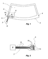
- a window 1 which can be a window composite of glass and / or synthetic material or monolithic window, carries along its edge device an opaque coating 2. This surrounds the field of vision of the glass, moreover transparent and covers a border 4 particularly wide along a curved (lower) edge 3 of the 1.
- a zone of connection 5 in which several tracks conductors 6 of a conductive structure, which are not represented here only in part, extend connecting surfaces that are gathered closely, is provided in a manner known per se a surface of the window.
- the surface of the window 1 which is directed towards the interior space of the vehicle when mounted on a vehicle.
- connection zone 5 In the connection zone 5 is arranged an element 7 welding connection, which is shown here on an exaggerated scale and which also known per se, serves to simultaneously contact electrical connecting surfaces, collected in the connection zone 5, of the structure conductive and electrical components arranged out glass (amplifier, control units, source Of voltage).
- an element 7 welding connection which is shown here on an exaggerated scale and which also known per se, serves to simultaneously contact electrical connecting surfaces, collected in the connection zone 5, of the structure conductive and electrical components arranged out glass (amplifier, control units, source Of voltage).
- amplifier, control units, source Of voltage At its free end opposite the window 1, we have symbolically indicated a multiple form 8 which, when the window 1 is mounted, can be connected to the vehicle or component circuit board mentioned above.
- the conductive structure may for example be a field antenna (for example diversity antenna) and / or a printed and baked heating field, a coating electrically conductive and thermally insulating by contact, etc.
- a field antenna for example diversity antenna
- a printed and baked heating field a coating electrically conductive and thermally insulating by contact, etc.
- its function is not not important and is therefore not explained anymore in detail.
- Figure 2 shows an enlarged view of the contact side of the welding connection element 7 made as a flat-band conductor and who, when he was mounted, is turned towards the support or the surface of the glass 1.
- the welding connection element 7 includes three electrical conductors 9 which parallel to one another and which have the shape of thin strips of leaf metallic.
- these strips of metal foil extend into surfaces which are left bare and have welding, see figure 3.
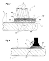
- the conductive tracks 9 of the element 7 of connection by welding are basically encompassed completely by two thin sheets of overlap 11 and 12 electrically insulating.
- they are made of a synthetic material which resistant to heat, for example polyimide, known also under the name of "Capton".
- the welding connection element 7 is then applied with solder deposits 14 on surfaces 15 made in the zone of connection 5 of the glass 1, the end points forming the associated conductive tracks 6 shown in Figure 1.
- a tool for 16 welding suitable over the entire surface of the connection zone 5 located on the surface of the welding connection element 7 turned towards the 1.
- This tool will apply at least the force of mechanical thrust required; he can also bring the necessary energy to melt the welding deposit 14 ("thermode"). We can bring directly from the heat that runs through the sheet upper recovery, or melt the deposit of induction heating welding.
- This last technique is also possible with a tool appropriate (not shown here) from the side of the window 1 which is not facing the zone of connection 5; tool 16 is then only used to mechanically maintain element 7 of connection by welding.
- Figure 4 shows the state of the connection area immediately after the melting of the weld deposit 14. If we compare it to Figure 3, we see that element 7 welding connection was slightly sunk towards the surface of the glass 1. It can be seen that the cutting edges 13 in the cover sheet 11 are located on the connecting surfaces 15. From this way they act as distancers by not not allowing the connection element 7 by welding or at its contact surfaces 10 of move closer to the connecting surface 15.
- the connecting surfaces 15 do not overflow only a few tenths of a millimeter from the surface of the pane 1 and the opaque coating 2; by therefore, in reality, the lower side of the element 7 welding connection and the cover sheet 11 underneath rests at the surface of the glass and thus guarantees the desired distance between the contact surfaces 10 and the connecting surfaces 15.
- a crash side of the weld in excess or too thick Low welding in the bond area are so virtually excluded.
- connection zone can still be protected by an adhesive seal 17 vis-à-vis environmental influences (fouling, humidity). It can also help to shed mechanically the connection area and the welded locations completed.
- the sealing 17 may as well be applied on the welding connection element 7 itself or on the connection zone 5 before the placement of the element 7 welding connection on the glass, for example in the form of a double adhesive tape face or the like. We can also realize the sealing after welding with glue pasty, which has the advantage of avoiding thermal damage by the heat of welding.
Landscapes
- Engineering & Computer Science (AREA)
- Manufacturing & Machinery (AREA)
- Microelectronics & Electronic Packaging (AREA)
- Connections Effected By Soldering, Adhesion, Or Permanent Deformation (AREA)
- Battery Mounting, Suspending (AREA)
- Manufacturing Of Electrical Connectors (AREA)
Abstract
Description
Claims (11)
- Elément (7) de raccordement par soudage pour au moins une surface de contact (10) d'un conducteur électrique (9) qui doit être soudé à une structure conductrice prévue sur un support (1), le conducteur électrique (9) étant recouvert au moins sur le côté qui doit être tourné vers le support (1) par une feuille de recouvrement (11, 12) isolante qui est dotée d'une découpe (13) dans la zone de la surface de contact (10) et dont le bord entoure en anneau la surface de contact, caractérisé en ce que par dimensionnement de l'épaisseur de la feuille de recouvrement (11) et de la surface de sa découpe (13) dans la zone de la surface de contact (10), on crée un espace harmonisé par rapport au volume prédéterminé de métal d'un dépôt de soudure (14) à appliquer sur la surface de contact (10), cet espace pouvant être exactement rempli par la soudure lors de la fusion de celle-ci.
- Elément de raccordement par soudage selon la revendication 1, qui fait partie d'un conducteur plat doté d'au moins une bande de feuille métallique (9) électriquement conductrice et d'une enveloppe isolante (11, 12) en plusieurs couches qui entoure celle-ci et qui comprend également la feuille de recouvrement (11) à appliquer sur le support (1).
- Elément de raccordement pas soudage selon l'une des revendications précédentes, caractérisé en ce que la feuille de recouvrement (11) est dotée pour chacune des surfaces de contact (10) à souder d'une pluralité de conducteurs électriques avec une découpe (13) associée qui entoure chaque surface de contact (10).
- Elément de raccordement par soudage selon l'une des revendications précédentes, caractérisé en ce que la feuille de recouvrement (11) résiste suffisamment à la pression pour ne pas se déformer même lors d'une poussée non négligeable d'un outil de soudage (16) appliqué sur le côté de l'élément de raccordement par soudage qui n'est pas tourné vers le support (1).
- Elément de raccordement par soudage selon l'une des revendications précédentes, caractérisé en ce que le conducteur électrique présente dans toute la région de la surface de contact au moins prévue et de la découpe dans la feuille de recouvrement une résistance accrue à la flexion.
- Utilisation d'un élément de raccordement par soudage selon l'une des revendications précédentes pour assurer le contact électrique entre une structure conductrice prévue sur une vitre, en particulier une vitre de véhicule, en particulier d'une structure d'antenne et/ou une structure de conducteur de chauffage, et des composants électriques associés.
- Vitre de véhicule, en particulier vitre en verre, qui comporte au moins un élément (7) de raccordement par soudage disposé sur une zone de raccordement (5) d'une structure conductrice qui comprend des pistes conductrices (6) et selon l'une des revendications précédentes.
- Vitre pour véhicule selon la revendication 7, dans laquelle la zone de raccordement est protégée des influences extérieures au moyen d'un scellement adhésif (17).
- Procédé pour la réalisation d'un raccordement par soudage d'un conducteur électrique et d'une surface de contact qui présente un dépôt de soudure avec un volume de métal prédéterminé sur une structure conductrice prévue sur un support, par recours à un élément de raccordement par soudage selon l'une des revendications 1 à 6 qui précèdent, le conducteur étant recouvert au moins sur son côté qui doit être tourné vers le support par une feuille de recouvrement électriquement isolante qui présente dans la zone de ladite surface de contact une découpe dont le bord entoure la surface de contact en anneau, caractérisé par les étapes qui consistent à :réaliser la découpe pour chaque surface de contact individuelle de telle sorte que sa surface et l'épaisseur de la feuille de recouvrement délimitent dans la zone de la surface de contact un espace harmonisé au volume du dépôt de soudure qui doit être au plus rempli exactement lors de la fusion de la soudure,appliquer sur la surface de contact un dépôt de soudure qui contient une quantité de soudure qui correspond au volume de la découpe recouverte par le support,appliquer la feuille de recouvrement sur le support et appliquer la surface de contact avec le dépôt de soudure sur une surface de raccordement associée de la structure conductrice,repousser un outil de soudage dans la région de la surface de contact etfaire fondre la soudure pour réaliser la liaison électrique permanente.
- Procédé selon la revendication 9, caractérisé en ce que la chaleur de fusion du dépôt de soudure est créée par un outil de soudage appliqué sur le côté du conducteur qui n'est pas tourné vers le support et qui sert également de contre-appui mécanique.
- Procédé selon la revendication 9, caractérisé en ce que la chaleur de fusion du dépôt de soudure est créée par l'apport d'énergie, en particulier par chauffage du dépôt de soudure par induction, qui traverse le support, l'outil de soudage appliqué sur le côté du conducteur qui n'est pas tourné vers le support constituant un contre-appui mécanique.
Applications Claiming Priority (2)
| Application Number | Priority Date | Filing Date | Title |
|---|---|---|---|
| DE10301352 | 2003-01-16 | ||
| DE10301352A DE10301352B3 (de) | 2003-01-16 | 2003-01-16 | Lötanschlusselement sowie Verfahren zum Herstellen eines Lötanschlusses |
Publications (3)
| Publication Number | Publication Date |
|---|---|
| EP1439600A2 true EP1439600A2 (fr) | 2004-07-21 |
| EP1439600A3 EP1439600A3 (fr) | 2004-12-15 |
| EP1439600B1 EP1439600B1 (fr) | 2018-05-09 |
Family
ID=32519983
Family Applications (1)
| Application Number | Title | Priority Date | Filing Date |
|---|---|---|---|
| EP04290025.8A Expired - Lifetime EP1439600B1 (fr) | 2003-01-16 | 2004-01-07 | Elément de raccordement par soudage |
Country Status (4)
| Country | Link |
|---|---|
| EP (1) | EP1439600B1 (fr) |
| DE (1) | DE10301352B3 (fr) |
| ES (1) | ES2682599T3 (fr) |
| PT (1) | PT1439600T (fr) |
Cited By (5)
| Publication number | Priority date | Publication date | Assignee | Title |
|---|---|---|---|---|
| WO2008027148A1 (fr) * | 2006-08-31 | 2008-03-06 | Antaya Technologies Corporation | Bande de barre omnibus |
| WO2009015975A1 (fr) | 2007-07-30 | 2009-02-05 | Pilkington Automotive Deutschland Gmbh | Connecteur électrique amélioré |
| EP3001782A4 (fr) * | 2013-11-15 | 2017-03-22 | Wonder Future Corporation | Procédé de fabrication d'un produit électrique |
| CN111856830A (zh) * | 2019-09-29 | 2020-10-30 | 法国圣戈班玻璃公司 | 具有分区段调控功能的玻璃以及玻璃分区段调控系统 |
| WO2021239937A1 (fr) | 2020-05-29 | 2021-12-02 | Agc Glass Europe | Connecteur plat pour brasage sur verre feuilleté |
Families Citing this family (8)
| Publication number | Priority date | Publication date | Assignee | Title |
|---|---|---|---|---|
| DE102005009443A1 (de) * | 2005-03-02 | 2006-09-07 | Hirschmann Electronics Gmbh | Folienantenne für ein Fahrzeug |
| US20070137141A1 (en) * | 2005-11-30 | 2007-06-21 | Hirschmann Car Communication Gmbh | Integration of functional layers in or on transparent plastic parts for vehicle manufacture |
| DE102008006647A1 (de) * | 2008-01-29 | 2009-07-30 | Few Fahrzeugelektrik Werk Gmbh & Co. Kg | Folienanschluss |
| CN103636060B (zh) | 2011-04-06 | 2016-03-23 | 法国圣戈班玻璃厂 | 用于天线结构的扁平导体连接元件 |
| PL3235339T3 (pl) | 2014-12-16 | 2019-08-30 | Saint-Gobain Glass France | Elektrycznie podgrzewana szyba antenowa jak również sposób jej wytwarzania |
| ES2849948T3 (es) | 2015-04-08 | 2021-08-24 | Saint Gobain | Luna con antena para vehículos |
| CN106463812A (zh) | 2015-04-08 | 2017-02-22 | 法国圣戈班玻璃厂 | 天线玻璃板 |
| DE102022209231A1 (de) * | 2022-09-06 | 2024-03-07 | Zf Friedrichshafen Ag | Verfahren zum Verbinden von zwei elektrisch leitfähigen Abschnitten eines Steuergeräts |
Family Cites Families (6)
| Publication number | Priority date | Publication date | Assignee | Title |
|---|---|---|---|---|
| US5014162A (en) * | 1989-06-27 | 1991-05-07 | At&T Bell Laboratories | Solder assembly of components |
| DE4132995A1 (de) * | 1991-10-04 | 1993-04-08 | Bodenseewerk Geraetetech | Verfahren zur herstellung elektrisch leitender verbindungen an leiterplatten |
| DE4304788C2 (de) * | 1993-02-17 | 1996-05-15 | Ver Glaswerke Gmbh | Verfahren zur Herstellung einer Leiterstruktur mit sich kreuzenden elektrischen Leitern auf der Oberfläche einer Glasscheibe |
| DE19856663C2 (de) * | 1998-12-09 | 2003-04-03 | Saint Gobain Sekurit D Gmbh | Kontaktvorrichtung für ein an einer Fensterscheibe angeordnetes elektrisches Funktionselement |
| JP2001230339A (ja) * | 2000-02-18 | 2001-08-24 | Nec Corp | 半導体装置 |
| DE10046489C1 (de) * | 2000-06-02 | 2001-12-20 | Saint Gobain Sekurit D Gmbh | Lötbares elektrisches Anschlußelement mit Lotdepot und dessen Verwendung |
-
2003
- 2003-01-16 DE DE10301352A patent/DE10301352B3/de not_active Expired - Lifetime
-
2004
- 2004-01-07 PT PT04290025T patent/PT1439600T/pt unknown
- 2004-01-07 ES ES04290025.8T patent/ES2682599T3/es not_active Expired - Lifetime
- 2004-01-07 EP EP04290025.8A patent/EP1439600B1/fr not_active Expired - Lifetime
Cited By (15)
| Publication number | Priority date | Publication date | Assignee | Title |
|---|---|---|---|---|
| WO2008027148A1 (fr) * | 2006-08-31 | 2008-03-06 | Antaya Technologies Corporation | Bande de barre omnibus |
| US9012776B2 (en) | 2006-08-31 | 2015-04-21 | Antaya Technologies Corporation | Buss bar strip |
| US7700878B2 (en) | 2006-08-31 | 2010-04-20 | Antaya Technologies Corporation | Buss bar strip |
| US8779291B2 (en) | 2006-08-31 | 2014-07-15 | Antaya Technologies Corporation | Buss bar strip |
| US7902460B2 (en) | 2006-08-31 | 2011-03-08 | Antaya Technologies Corporation | Buss bar strip |
| US8222523B2 (en) | 2006-08-31 | 2012-07-17 | Antaya Technologies Corporation | Buss bar strip |
| US8373067B2 (en) | 2007-07-30 | 2013-02-12 | Pilkington Automotive Deutschland Gmbh | Electrical connector |
| US20100193242A1 (en) * | 2007-07-30 | 2010-08-05 | Pilkington Automotive Deutschland Gmbh | Electrical connector |
| WO2009015975A1 (fr) | 2007-07-30 | 2009-02-05 | Pilkington Automotive Deutschland Gmbh | Connecteur électrique amélioré |
| EP3001782A4 (fr) * | 2013-11-15 | 2017-03-22 | Wonder Future Corporation | Procédé de fabrication d'un produit électrique |
| US9949375B2 (en) | 2013-11-15 | 2018-04-17 | Wonder Future Corporation | Method for manufacturing an electric product |
| CN111856830A (zh) * | 2019-09-29 | 2020-10-30 | 法国圣戈班玻璃公司 | 具有分区段调控功能的玻璃以及玻璃分区段调控系统 |
| WO2021239937A1 (fr) | 2020-05-29 | 2021-12-02 | Agc Glass Europe | Connecteur plat pour brasage sur verre feuilleté |
| EP4158734A1 (fr) * | 2020-05-29 | 2023-04-05 | AGC Glass Europe | Connecteur plat pour brasage sur verre feuilleté |
| US12212107B2 (en) | 2020-05-29 | 2025-01-28 | Agc Glass Europe | Flat connector for soldering on laminated glass |
Also Published As
| Publication number | Publication date |
|---|---|
| EP1439600A3 (fr) | 2004-12-15 |
| DE10301352B3 (de) | 2004-07-15 |
| ES2682599T3 (es) | 2018-09-21 |
| EP1439600B1 (fr) | 2018-05-09 |
| PT1439600T (pt) | 2018-10-01 |
Similar Documents
| Publication | Publication Date | Title |
|---|---|---|
| EP1439600B1 (fr) | Elément de raccordement par soudage | |
| EP1803327B1 (fr) | Vitrage transparent avec un revetement chauffant resistif | |
| EP1559296B1 (fr) | Vitre transparente avec surface de contact non transparente pour une liaison par brasage | |
| EP1817942B1 (fr) | Procede et dispositif pour braser des raccords par chauffage inductif | |
| EP1980137B1 (fr) | Vitrage transparent muni d'un systeme stratifie chauffant | |
| EP0394089B1 (fr) | Vitrage automobile chauffable électriquement | |
| FR2921520A1 (fr) | Element de connexion electrique et vitrage pourvu d'un tel element | |
| EP2649566B1 (fr) | Carte électronique ayant un connecteur externe | |
| EP1627555B1 (fr) | Element feuillete dote d'une couche chauffante | |
| EP0527680B1 (fr) | Raccordement de vitrages à couche électroconductrice | |
| FR2549296A1 (fr) | Procede de fabrication d'une pile solaire | |
| WO2003026869A1 (fr) | Procede pour fabriquer une vitre en matiere plastique avec une structure de conducteurs electriques et vitre en matiere plastique avec fils noyes | |
| EP1160937B1 (fr) | Elément de raccordement électrique soudable avec dépôt de soudure | |
| FR2670070A1 (fr) | Pieces de connexion pour vitrages electrifies. | |
| EP0490723A1 (fr) | Vitrage en verre feuilleté chauffable avec élément de connexion de câble | |
| BE1004164A3 (fr) | Substrat en verre portant un circuit electrique et sa methode de fabrication. | |
| FR2458978A2 (fr) | Procede et dispositif d'interconnexions de composants electronique | |
| FR2630550A1 (fr) | Procede de montage d'elements optiques sur un support et circuit optique ainsi obtenu | |
| FR2850489A1 (fr) | Procede de realisation d'un module photovoltaique et module photovoltaique realise par ce procede | |
| WO2005004539A1 (fr) | Element en plaque avec un chauffage en couche | |
| EP1806032B1 (fr) | Dispositif de chauffage de sols, notamment recouverts d'un revetement de synthese | |
| EP0242667B1 (fr) | Outil de soudage pour dispositifs électroniques | |
| EP1079259A1 (fr) | Procédé de réalisation d'un module d'affichage à cellule à cristaux liquides | |
| FR2644011A1 (fr) | Procede de realisation de contacts pour des electrodes en couche mince sur du verre | |
| FR2472903A1 (fr) | Piece de fixation d'un composant sur un substrat et procede de fixation |
Legal Events
| Date | Code | Title | Description |
|---|---|---|---|
| PUAI | Public reference made under article 153(3) epc to a published international application that has entered the european phase |
Free format text: ORIGINAL CODE: 0009012 |
|
| 17P | Request for examination filed |
Effective date: 20040113 |
|
| AK | Designated contracting states |
Kind code of ref document: A2 Designated state(s): AT BE BG CH CY CZ DE DK EE ES FI FR GB GR HU IE IT LI LU MC NL PT RO SE SI SK TR |
|
| AX | Request for extension of the european patent |
Extension state: AL LT LV MK |
|
| PUAL | Search report despatched |
Free format text: ORIGINAL CODE: 0009013 |
|
| AK | Designated contracting states |
Kind code of ref document: A3 Designated state(s): AT BE BG CH CY CZ DE DK EE ES FI FR GB GR HU IE IT LI LU MC NL PT RO SE SI SK TR |
|
| AX | Request for extension of the european patent |
Extension state: AL LT LV MK |
|
| AKX | Designation fees paid |
Designated state(s): AT BE BG CH CY CZ DE DK EE ES FI FR GB GR HU IE IT LI LU MC NL PT RO SE SI SK TR |
|
| 17Q | First examination report despatched |
Effective date: 20070531 |
|
| RIC1 | Information provided on ipc code assigned before grant |
Ipc: H01R 12/62 20110101ALI20170526BHEP Ipc: H05K 3/36 20060101ALI20170526BHEP Ipc: H01R 43/02 20060101ALI20170526BHEP Ipc: H05K 3/28 20060101ALI20170526BHEP Ipc: H01Q 1/32 20060101ALI20170526BHEP Ipc: H01R 13/20 20060101ALI20170526BHEP Ipc: H05K 3/34 20060101ALI20170526BHEP Ipc: H01Q 1/12 20060101AFI20170526BHEP |
|
| GRAP | Despatch of communication of intention to grant a patent |
Free format text: ORIGINAL CODE: EPIDOSNIGR1 |
|
| STAA | Information on the status of an ep patent application or granted ep patent |
Free format text: STATUS: GRANT OF PATENT IS INTENDED |
|
| INTG | Intention to grant announced |
Effective date: 20170913 |
|
| GRAJ | Information related to disapproval of communication of intention to grant by the applicant or resumption of examination proceedings by the epo deleted |
Free format text: ORIGINAL CODE: EPIDOSDIGR1 |
|
| STAA | Information on the status of an ep patent application or granted ep patent |
Free format text: STATUS: EXAMINATION IS IN PROGRESS |
|
| INTC | Intention to grant announced (deleted) | ||
| GRAP | Despatch of communication of intention to grant a patent |
Free format text: ORIGINAL CODE: EPIDOSNIGR1 |
|
| STAA | Information on the status of an ep patent application or granted ep patent |
Free format text: STATUS: GRANT OF PATENT IS INTENDED |
|
| INTG | Intention to grant announced |
Effective date: 20180119 |
|
| GRAS | Grant fee paid |
Free format text: ORIGINAL CODE: EPIDOSNIGR3 |
|
| GRAA | (expected) grant |
Free format text: ORIGINAL CODE: 0009210 |
|
| STAA | Information on the status of an ep patent application or granted ep patent |
Free format text: STATUS: THE PATENT HAS BEEN GRANTED |
|
| AK | Designated contracting states |
Kind code of ref document: B1 Designated state(s): AT BE BG CH CY CZ DE DK EE ES FI FR GB GR HU IE IT LI LU MC NL PT RO SE SI SK TR |
|
| REG | Reference to a national code |
Ref country code: GB Ref legal event code: FG4D Free format text: NOT ENGLISH |
|
| REG | Reference to a national code |
Ref country code: CH Ref legal event code: EP Ref country code: AT Ref legal event code: REF Ref document number: 998345 Country of ref document: AT Kind code of ref document: T Effective date: 20180515 |
|
| REG | Reference to a national code |
Ref country code: IE Ref legal event code: FG4D Free format text: LANGUAGE OF EP DOCUMENT: FRENCH |
|
| REG | Reference to a national code |
Ref country code: DE Ref legal event code: R096 Ref document number: 602004052683 Country of ref document: DE |
|
| REG | Reference to a national code |
Ref country code: NL Ref legal event code: FP |
|
| REG | Reference to a national code |
Ref country code: SE Ref legal event code: TRGR |
|
| REG | Reference to a national code |
Ref country code: ES Ref legal event code: FG2A Ref document number: 2682599 Country of ref document: ES Kind code of ref document: T3 Effective date: 20180921 |
|
| REG | Reference to a national code |
Ref country code: PT Ref legal event code: SC4A Ref document number: 1439600 Country of ref document: PT Date of ref document: 20181001 Kind code of ref document: T Free format text: AVAILABILITY OF NATIONAL TRANSLATION Effective date: 20180808 |
|
| PG25 | Lapsed in a contracting state [announced via postgrant information from national office to epo] |
Ref country code: BG Free format text: LAPSE BECAUSE OF FAILURE TO SUBMIT A TRANSLATION OF THE DESCRIPTION OR TO PAY THE FEE WITHIN THE PRESCRIBED TIME-LIMIT Effective date: 20180809 Ref country code: FI Free format text: LAPSE BECAUSE OF FAILURE TO SUBMIT A TRANSLATION OF THE DESCRIPTION OR TO PAY THE FEE WITHIN THE PRESCRIBED TIME-LIMIT Effective date: 20180509 |
|
| REG | Reference to a national code |
Ref country code: SK Ref legal event code: T3 Ref document number: E 27971 Country of ref document: SK |
|
| PG25 | Lapsed in a contracting state [announced via postgrant information from national office to epo] |
Ref country code: GR Free format text: LAPSE BECAUSE OF FAILURE TO SUBMIT A TRANSLATION OF THE DESCRIPTION OR TO PAY THE FEE WITHIN THE PRESCRIBED TIME-LIMIT Effective date: 20180810 |
|
| REG | Reference to a national code |
Ref country code: CH Ref legal event code: PK Free format text: RECTIFICATIONS |
|
| REG | Reference to a national code |
Ref country code: AT Ref legal event code: MK05 Ref document number: 998345 Country of ref document: AT Kind code of ref document: T Effective date: 20180509 |
|
| RIC2 | Information provided on ipc code assigned after grant |
Ipc: H05K 3/36 20060101ALI20170526BHEP Ipc: H01R 12/62 20110101ALI20170526BHEP Ipc: H05K 3/34 20060101ALI20170526BHEP Ipc: H01R 13/20 20060101ALI20170526BHEP Ipc: H05K 3/28 20060101ALI20170526BHEP Ipc: H01Q 1/32 20060101ALI20170526BHEP Ipc: H01Q 1/12 20060101AFI20170526BHEP Ipc: H01R 43/02 20060101ALI20170526BHEP |
|
| PG25 | Lapsed in a contracting state [announced via postgrant information from national office to epo] |
Ref country code: DK Free format text: LAPSE BECAUSE OF FAILURE TO SUBMIT A TRANSLATION OF THE DESCRIPTION OR TO PAY THE FEE WITHIN THE PRESCRIBED TIME-LIMIT Effective date: 20180509 Ref country code: AT Free format text: LAPSE BECAUSE OF FAILURE TO SUBMIT A TRANSLATION OF THE DESCRIPTION OR TO PAY THE FEE WITHIN THE PRESCRIBED TIME-LIMIT Effective date: 20180509 Ref country code: EE Free format text: LAPSE BECAUSE OF FAILURE TO SUBMIT A TRANSLATION OF THE DESCRIPTION OR TO PAY THE FEE WITHIN THE PRESCRIBED TIME-LIMIT Effective date: 20180509 |
|
| REG | Reference to a national code |
Ref country code: CH Ref legal event code: PK Free format text: RECTIFICATIONS |
|
| REG | Reference to a national code |
Ref country code: DE Ref legal event code: R097 Ref document number: 602004052683 Country of ref document: DE |
|
| RIC2 | Information provided on ipc code assigned after grant |
Ipc: H05K 3/34 20060101ALI20170526BHEP Ipc: H01R 43/02 20060101ALI20170526BHEP Ipc: H05K 3/28 20060101ALI20170526BHEP Ipc: H01R 13/20 20060101ALI20170526BHEP Ipc: H01Q 1/32 20060101ALI20170526BHEP Ipc: H01R 12/62 20110101ALI20170526BHEP Ipc: H05K 3/36 20060101ALI20170526BHEP Ipc: H01Q 1/12 20060101AFI20170526BHEP |
|
| PLBE | No opposition filed within time limit |
Free format text: ORIGINAL CODE: 0009261 |
|
| STAA | Information on the status of an ep patent application or granted ep patent |
Free format text: STATUS: NO OPPOSITION FILED WITHIN TIME LIMIT |
|
| 26N | No opposition filed |
Effective date: 20190212 |
|
| PG25 | Lapsed in a contracting state [announced via postgrant information from national office to epo] |
Ref country code: SI Free format text: LAPSE BECAUSE OF FAILURE TO SUBMIT A TRANSLATION OF THE DESCRIPTION OR TO PAY THE FEE WITHIN THE PRESCRIBED TIME-LIMIT Effective date: 20180509 |
|
| REG | Reference to a national code |
Ref country code: RO Ref legal event code: EPE |
|
| PG25 | Lapsed in a contracting state [announced via postgrant information from national office to epo] |
Ref country code: MC Free format text: LAPSE BECAUSE OF FAILURE TO SUBMIT A TRANSLATION OF THE DESCRIPTION OR TO PAY THE FEE WITHIN THE PRESCRIBED TIME-LIMIT Effective date: 20180509 |
|
| REG | Reference to a national code |
Ref country code: CH Ref legal event code: PL |
|
| REG | Reference to a national code |
Ref country code: IE Ref legal event code: MM4A |
|
| PG25 | Lapsed in a contracting state [announced via postgrant information from national office to epo] |
Ref country code: CH Free format text: LAPSE BECAUSE OF NON-PAYMENT OF DUE FEES Effective date: 20190131 Ref country code: LI Free format text: LAPSE BECAUSE OF NON-PAYMENT OF DUE FEES Effective date: 20190131 |
|
| PG25 | Lapsed in a contracting state [announced via postgrant information from national office to epo] |
Ref country code: IE Free format text: LAPSE BECAUSE OF NON-PAYMENT OF DUE FEES Effective date: 20190107 |
|
| PGFP | Annual fee paid to national office [announced via postgrant information from national office to epo] |
Ref country code: PT Payment date: 20200102 Year of fee payment: 17 Ref country code: SE Payment date: 20200110 Year of fee payment: 17 |
|
| PG25 | Lapsed in a contracting state [announced via postgrant information from national office to epo] |
Ref country code: CY Free format text: LAPSE BECAUSE OF FAILURE TO SUBMIT A TRANSLATION OF THE DESCRIPTION OR TO PAY THE FEE WITHIN THE PRESCRIBED TIME-LIMIT Effective date: 20180509 |
|
| PG25 | Lapsed in a contracting state [announced via postgrant information from national office to epo] |
Ref country code: HU Free format text: LAPSE BECAUSE OF FAILURE TO SUBMIT A TRANSLATION OF THE DESCRIPTION OR TO PAY THE FEE WITHIN THE PRESCRIBED TIME-LIMIT; INVALID AB INITIO Effective date: 20040107 |
|
| REG | Reference to a national code |
Ref country code: SE Ref legal event code: EUG |
|
| PG25 | Lapsed in a contracting state [announced via postgrant information from national office to epo] |
Ref country code: SE Free format text: LAPSE BECAUSE OF NON-PAYMENT OF DUE FEES Effective date: 20210108 Ref country code: PT Free format text: LAPSE BECAUSE OF NON-PAYMENT OF DUE FEES Effective date: 20210707 |
|
| PGFP | Annual fee paid to national office [announced via postgrant information from national office to epo] |
Ref country code: RO Payment date: 20211228 Year of fee payment: 19 Ref country code: SK Payment date: 20211214 Year of fee payment: 19 Ref country code: CZ Payment date: 20211215 Year of fee payment: 19 Ref country code: LU Payment date: 20211224 Year of fee payment: 19 |
|
| PGFP | Annual fee paid to national office [announced via postgrant information from national office to epo] |
Ref country code: NL Payment date: 20211216 Year of fee payment: 19 Ref country code: BE Payment date: 20211221 Year of fee payment: 19 |
|
| PGFP | Annual fee paid to national office [announced via postgrant information from national office to epo] |
Ref country code: ES Payment date: 20220203 Year of fee payment: 19 |
|
| PGFP | Annual fee paid to national office [announced via postgrant information from national office to epo] |
Ref country code: GB Payment date: 20221201 Year of fee payment: 20 |
|
| PGFP | Annual fee paid to national office [announced via postgrant information from national office to epo] |
Ref country code: FR Payment date: 20230130 Year of fee payment: 20 |
|
| PGFP | Annual fee paid to national office [announced via postgrant information from national office to epo] |
Ref country code: TR Payment date: 20230105 Year of fee payment: 20 Ref country code: IT Payment date: 20221213 Year of fee payment: 20 Ref country code: DE Payment date: 20221130 Year of fee payment: 20 |
|
| PG25 | Lapsed in a contracting state [announced via postgrant information from national office to epo] |
Ref country code: CZ Free format text: LAPSE BECAUSE OF NON-PAYMENT OF DUE FEES Effective date: 20230107 |
|
| REG | Reference to a national code |
Ref country code: SK Ref legal event code: MM4A Ref document number: E 27971 Country of ref document: SK Effective date: 20230107 |
|
| REG | Reference to a national code |
Ref country code: NL Ref legal event code: MM Effective date: 20230201 |
|
| PG25 | Lapsed in a contracting state [announced via postgrant information from national office to epo] |
Ref country code: LU Free format text: LAPSE BECAUSE OF NON-PAYMENT OF DUE FEES Effective date: 20230107 |
|
| REG | Reference to a national code |
Ref country code: BE Ref legal event code: MM Effective date: 20230131 |
|
| PG25 | Lapsed in a contracting state [announced via postgrant information from national office to epo] |
Ref country code: RO Free format text: LAPSE BECAUSE OF NON-PAYMENT OF DUE FEES Effective date: 20230107 Ref country code: NL Free format text: LAPSE BECAUSE OF NON-PAYMENT OF DUE FEES Effective date: 20230201 |
|
| PG25 | Lapsed in a contracting state [announced via postgrant information from national office to epo] |
Ref country code: SK Free format text: LAPSE BECAUSE OF NON-PAYMENT OF DUE FEES Effective date: 20230107 Ref country code: BE Free format text: LAPSE BECAUSE OF NON-PAYMENT OF DUE FEES Effective date: 20230131 |
|
| REG | Reference to a national code |
Ref country code: DE Ref legal event code: R071 Ref document number: 602004052683 Country of ref document: DE |
|
| REG | Reference to a national code |
Ref country code: GB Ref legal event code: PE20 Expiry date: 20240106 |
|
| REG | Reference to a national code |
Ref country code: ES Ref legal event code: FD2A Effective date: 20240229 |
|
| PG25 | Lapsed in a contracting state [announced via postgrant information from national office to epo] |
Ref country code: ES Free format text: LAPSE BECAUSE OF NON-PAYMENT OF DUE FEES Effective date: 20230108 |
|
| PG25 | Lapsed in a contracting state [announced via postgrant information from national office to epo] |
Ref country code: ES Free format text: LAPSE BECAUSE OF NON-PAYMENT OF DUE FEES Effective date: 20230108 Ref country code: GB Free format text: LAPSE BECAUSE OF EXPIRATION OF PROTECTION Effective date: 20240106 |