EP1439491B1 - Signal processing method and processor - Google Patents
Signal processing method and processor Download PDFInfo
- Publication number
- EP1439491B1 EP1439491B1 EP02802019A EP02802019A EP1439491B1 EP 1439491 B1 EP1439491 B1 EP 1439491B1 EP 02802019 A EP02802019 A EP 02802019A EP 02802019 A EP02802019 A EP 02802019A EP 1439491 B1 EP1439491 B1 EP 1439491B1
- Authority
- EP
- European Patent Office
- Prior art keywords
- image
- similarity
- signal processing
- image data
- value
- Prior art date
- Legal status (The legal status is an assumption and is not a legal conclusion. Google has not performed a legal analysis and makes no representation as to the accuracy of the status listed.)
- Expired - Fee Related
Links
Images


Classifications
-
- G—PHYSICS
- G06—COMPUTING; CALCULATING OR COUNTING
- G06T—IMAGE DATA PROCESSING OR GENERATION, IN GENERAL
- G06T7/00—Image analysis
- G06T7/0002—Inspection of images, e.g. flaw detection
-
- G—PHYSICS
- G06—COMPUTING; CALCULATING OR COUNTING
- G06T—IMAGE DATA PROCESSING OR GENERATION, IN GENERAL
- G06T7/00—Image analysis
- G06T7/30—Determination of transform parameters for the alignment of images, i.e. image registration
- G06T7/32—Determination of transform parameters for the alignment of images, i.e. image registration using correlation-based methods
-
- G—PHYSICS
- G06—COMPUTING; CALCULATING OR COUNTING
- G06V—IMAGE OR VIDEO RECOGNITION OR UNDERSTANDING
- G06V10/00—Arrangements for image or video recognition or understanding
- G06V10/40—Extraction of image or video features
- G06V10/44—Local feature extraction by analysis of parts of the pattern, e.g. by detecting edges, contours, loops, corners, strokes or intersections; Connectivity analysis, e.g. of connected components
- G06V10/443—Local feature extraction by analysis of parts of the pattern, e.g. by detecting edges, contours, loops, corners, strokes or intersections; Connectivity analysis, e.g. of connected components by matching or filtering
-
- G—PHYSICS
- G06—COMPUTING; CALCULATING OR COUNTING
- G06V—IMAGE OR VIDEO RECOGNITION OR UNDERSTANDING
- G06V10/00—Arrangements for image or video recognition or understanding
- G06V10/70—Arrangements for image or video recognition or understanding using pattern recognition or machine learning
- G06V10/74—Image or video pattern matching; Proximity measures in feature spaces
- G06V10/75—Organisation of the matching processes, e.g. simultaneous or sequential comparisons of image or video features; Coarse-fine approaches, e.g. multi-scale approaches; using context analysis; Selection of dictionaries
- G06V10/751—Comparing pixel values or logical combinations thereof, or feature values having positional relevance, e.g. template matching
- G06V10/7515—Shifting the patterns to accommodate for positional errors
Definitions
- This invention relates to a signal processing method and device, a signal processing program, and a recording medium, and particularly to a signal processing method and device, a signal processing program, and a recording medium having a signal processing program recorded thereon for evaluating the similarity in the case where plural image data include a similar pattern.
- partly identical or similar patterns such as images of similar scenes in a video (a collective time section in the video), a logo of a company name in a commercial, and a characters or pattern indicating an owner inserted in an image may be included in different images.
- these similar patterns used because they are related to each image or video to a certain extent. If the similarity can be detected and evaluated, search for and classification or collection of related image or video scenes can be realized.
- Figs. 1A and 1B show different images in which the same logo "ABE" is inserted.
- a logo represents, for example, information of an owner of the two images or an enterprise providing a product of a commercial image.
- substantially the same logo may be inserted at different positions in the images.
- the positions where such a logo is inserted cannot be specified in advance and what pattern is inserted cannot be known in advance, either.
- the pattern is separately prepared in advance by a certain technique and the pattern id detected by a correlative method, a histogram comparison method or the like.
- Japanese Laid-Open Patent Application No. 2000-312343 discloses a technique of fast search for the same image as an image that is registered in advance. However, this requires preparation of the same image as the image to be searched for, in advance. Moreover, this technique cannot be applied to detection of a partly similar image constituting a video.
- Japanese Laid-Open Patent Application No. H11-328311 discloses a technique of detecting a pattern similar to a registered pattern using a correlative method in the case where such a similar pattern exists at a certain position another image.
- this technique requires registration of the similar pattern in advance and it fails to detect and evaluate partial similarity between two arbitrary images from which a similar pattern cannot be found in advance.
- US 5,406,642 A describes that, in a block matching method, a successive one of segmented blocks of a first image is superimposed on a portion of a second image, and a correlation is detected therebetween.
- the superimposed block is successively moved by a small amount and correlations are repeatedly detected for different locations of the successively moved block.
- a maximum value of the correlations is detected and a vector representing the location of the block of the maximum correlation is stored into a memory as a match between a block of the first image and a portion of the second image.
- the process is repeated for the remaining blocks of the first image to create a map of the matching vectors in the memory.
- Direction sensitivity functions and vector smoothing functions are derived from the segmented blocks for respectively correcting the stored matching vectors.
- US 4,677,476 A describes a method for detecting a movement of a television signal corresponding to the movement of a television camera during a panning operation includes dividing a picture plane of the television signal into blocks and obtaining an absolute value of a difference between pixel values from two consecutive frames for each block.
- the absolute value is integrated and a block matching table of frame difference integration data is derived therefrom.
- An extremum value of the frame difference integration data is linearly obtained from a maximum gradient of four gradients taken in upper, lower, left and right gradient directions from the respective origin of each block using the block matching table. This extremum value may be compared with frame difference integration data taken in four oblique directions intermediate the gradient directions to verify the extremum value.
- a signal processing method includes: a division step of inputting plural image data and dividing at least one of the plural image data into plural small areas; a parameter extraction step of extracting a conversion parameter used for converting the small areas so that the small areas become similar to the other image data; a totaling step of totaling values indicating the degree of similarity found on the basis of the conversion parameter; and a similarity evaluation step of evaluating the similarity between the plural image data on the basis of the result of the totaling.
- the signal processing method may further include a similar area extraction step of extracting a similar area of the plural image data.
- the conversion parameter may be found using a correlative method.
- the conversion parameter is, for example, a position difference and/or luminance ratio at a point where a maximum correlation value between the small area and the other image data is obtained, and at the totaling step, values indicating the degree of similarity between the plural image data are totaled in a space centering the conversion parameter as an axis.
- At least one of inputted plural image data is divided into plural small areas and the similarity between each small area and the other image data is found. As these similarity values are totaled, the similarity between the plural image data is evaluated. On the basis of the similarity, a similar area of the plural image data may be extracted.
- the signal processing method may includes: a reproduction step of reproducing image data recorded in recording means; a designation step of designating desired image data from the image data that are being reproduced; and a similar area detection step of detecting a similar area of the desired image data and search target image data of the image data.
- the signal processing method according to the present invention may include: a similar area extraction step of extracting a similar area of the plural image data; a first coding step of coding the similar area of the plural image data extracted at the similar area extraction step; and a second coding step of coding the areas other than the similar area.
- the first coding step for example, information of position difference of the similar area, luminance ratio, and shape of the similar area is coded.
- At least one of inputted plural image data is divided into plural small areas and the similarity between each small area and the other image data is found. As the similarity values are totaled, the similarity between the plural image data is evaluated. On the basis of the similarity, a similar area of the plural image data may be extracted, and the similar area and the other areas may be separately coded.
- a signal processing device as an example useful for understanding the present invention includes: division means for inputting plural image data and dividing at least one of the plural image data into plural small areas; parameter extraction means for extracting a conversion parameter used for converting the small areas so that the small areas become similar to the other image data; totaling means for totaling values indicating the degree of similarity found on the basis of the conversion parameter; and similarity evaluation means for evaluating the similarity between the plural image data on the basis of the result of the totaling
- the signal processing device may further include similar area extraction means for extracting a similar area of the plural image data.
- the conversion parameter may be found using a correlative method.
- the conversion parameter is, for example, a position difference and/or luminance ratio at a point where a maximum correlation value between the small area and the other image data is obtained, and at the totaling means totals values indicating the degree of similarity between the plural image data in a space centering the conversion parameter as an axis.
- At least one of inputted plural image data is divided into plural small areas and the similarity between each small area and the other image data is found. As these similarity values are totaled, the similarity between the plural image data is evaluated. On the basis of the similarity, a similar area of the plural image data may be extracted.
- the signal processing device may include: recording means for recording plural image data; reproduction means for reproducing the image data recorded in the recording means; designation means for designating desired image data from the image data that are being reproduced; and similar area detection means for detecting a similar area of the desired image data and the search target image data of the image data.
- the image data when desired image data is designated from image data that are being reproduced, the image data is divided into small areas and the similarity between each small area and search target image data recorded in the recording means is found. As the similarity values are totaled, the similarity between the plural image data is evaluated and a similar area may be extracted on the basis of the similarity.
- the signal processing device may include: similar area extraction means for extracting a similar area of the plural image data; first coding means for coding the similar area of the plural image data extracted by the similar area extraction means; and second coding means for coding the areas other than the similar area.
- the first coding means codes, for example, information of position difference of the similar area, luminance ratio, and shape of the similar area.
- At least one of inputted plural image data is divided into plural small areas and the similarity between each small area and the other image data is found. As the similarity values are totaled, the similarity between the plural image data is evaluated. On the basis of the similarity, a similar area of the plural image data may be extracted, and the similar area and the other areas may be separately coded.
- a signal processing program as an example useful for understanding the present invention includes:a division step of inputting plural image data and dividing at least one of the plural image data into plural small areas; a parameter extraction step of extracting a conversion parameter used for converting the small areas so that the small areas become similar to the other image data; a totaling step of totaling values indicating the degree of similarity found on the basis of the conversion parameter; and a similarity evaluation step of evaluating the similarity between the plural image data on the basis of the result of the totaling
- the signal processing program may further include a similar area extraction step of extracting a similar area of the plural image data.
- the conversion parameter may be found using a correlative method.
- the conversion parameter is, for example, a position difference and/or luminance ratio at a point where a maximum correlation value between the small area and the other image data is obtained, and at the totaling step, values indicating the degree of similarity between the plural image data are totaled in a space centering the conversion parameter as an axis.
- At least one of inputted plural image data is divided into plural small areas and the similarity between each small area and the other image data is found. As these similarity values are totaled, the similarity between the plural image data is evaluated. On the basis of the similarity, a similar area of the plural image data may be extracted.
- the signal processing program may include: a reproduction step of reproducing image data recorded in recording means; a designation step of designating desired image data from the image data that are being reproduced; and a similar area detection step of detecting a similar area of the desired image data and the search target image data of the image data.
- the signal processing program according to the present invention may include: a similar area extraction step of extracting a similar area of the plural image data; a first coding step of coding the similar area of the plural image data extracted at the similar area extraction step; and a second coding step of coding the areas other than the similar area.
- the first coding step for example, information of position difference of the similar area, luminance ratio, and shape of the similar area is coded.
- At least one of inputted plural image data is divided into plural small areas and the similarity between each small area and the other image data is found. As the similarity values are totaled, the similarity between the plural image data is evaluated. On the basis of the similarity, a similar area of the plural image data may be extracted, and the similar area and the other areas may be separately coded.
- a recording medium as an example useful for understanding the present invention is a computer-controllable recording medium having a signal processing program recorded therein, the signal processing program including: a division step of inputting plural image data and dividing at least one of the plural image data into plural small areas; a parameter extraction step of extracting a conversion parameter used for converting the small areas so that the small areas become similar to the other image data; a totaling step of totaling values indicating the degree of similarity found on the basis of the conversion parameter; and a similarity evaluation step of evaluating the similarity between the plural image data on the basis of the result of the totaling
- the signal processing program may further include a similar area extraction step of extracting a similar area of the plural image data.
- the conversion parameter may be found using a correlative method.
- the conversion parameter is, for example, a position difference and/or luminance ratio at a point where a maximum correlation value between the small area and the other image data is obtained, and at the totaling step, values indicating the degree of similarity between the plural image data are totaled in a space centering the conversion parameter as an axis.
- the signal processing program recorded in such a recording medium at least one of inputted plural image data is divided into plural small areas and the similarity between each small area and the other image data is found. As these similarity values are totaled, the similarity between the plural image data is evaluated. On the basis of the similarity, a similar area of the plural image data may be extracted.
- the recording medium according to the present invention is a computer-controllable recording medium having a signal processingprogram recorded therein
- the signal processing program may include: a reproduction step of reproducing image data recorded in recording means; a designation step of designating desired image data from the image data that are being reproduced; and a similar area detection step of detecting a similar area of the desired image data and the search target image data of the image data.
- the signal processing program recorded in such a recording medium when desired image data is designated from image data that are being reproduced, the image data is divided into small areas and the similarity between each small area and search target image data recorded in the recording means is found. As the similarity values are totaled, the similarity between the plural image data is evaluated and a similar area may be extracted on the basis of the similarity.
- the recording medium according to the present invention is a computer-controllable recording medium having a signal processing program recorded therein, the signal processing program may be include: a similar area extraction step of extracting a similar area of the plural image data; a first coding step of coding the similar area of the plural image data extracted at the similar area extraction step; and a second coding step of coding the areas other than the similar area.
- the first coding step of the signal processing program for example, information of position difference of the similar area, luminance ratio, and shape of the similar area is coded.
- the signal processing program recorded in such a recording medium at least one of inputted plural image data is divided into plural small areas and the similarity between each small area and the other image data is found. As the similarity values are totaled, the similarity between the plural image data is evaluated. On the basis of the similarity, a similar area of the plural image data may be extracted, and the similar area and the other areas may be separately coded.
- the present invention is applied to a signal processing device which evaluates partial similarity of two or more arbitrary images and automatically extracts a similar area.
- two different images are used inputted images.
- two or more images may be used or plural images acquired from video data or plural partial images acquired from one image may also be used.
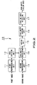
- Fig.2 shows the schematic structure of a signal processing device of this embodiment.
- a signal processing device 10 has a first preprocessing unit 11, an area dividing unit 12, a second preprocessing unit 13, a similarity calculating unit 14, a voting unit 15, a similarity judging unit 16, and a similar area detecting unit 17.
- the first preprocessing unit 11 performs, to a first image of the two images to be compared, known filter processing for extracting image characteristics such as differentiation or high-order differentiation, known transform processing such as color-reducing arithmetic operation, monochromatization or binarization processing, and processing to limit the subsequent processing range on the basis of the characteristic quantity of edge detection, edge density detection, local color histogram or the like. Preprocessing of a combination of the above-described processing may be performed. Alternatively, identical transform may be performed without performing any processing.
- the area dividing unit 12 divides the first image into small areas. For example, as shown in Fig.3A , the area dividing unit 12 divides the first image into 63 small areas. Of course, the number of divisions is not limited to this and can be arbitrarily set. However, it is preferred that the size of a small area is set to be much smaller than that of an anticipated similar area. For example, in the above-described example of Figs.1A and 1B , it is preferred that the logo "ABE" is set to be divided into at least plural areas. While the small areas in Fig.3A are divided in such a manner that they do not overlap each other, the small areas may overlap each other.
- the second preprocessing unit 13 performs preprocessing similar to that of the first preprocessing unit 11, to a second image of the two images to be compared. Alternatively, identical transform may be performed without performing any processing, as in the case of the first image.
- the similarity calculating unit 14 calculates the correlation between each of the small areas provided by division at the area dividing unit 12 and the second image. Normally, to calculate the correlation, correlation operation is performed for the entire range of the second image using each of the small areas as template, as shown in Fig.3B .
- the similarity calculating unit 14 searches for a small area having the largest correlation value of the resulting correlation values, and acquires the correlative value s, position difference dx, dy, and luminance ratio 1.
- the position difference is a parameter indicating the relative positional relation between the original position of this small area in the first image and the position where the maximum correlation value is obtained.
- the luminance ratio is a multiplication coefficient for the patter of the small area pattern such that the pattern of the small area and the pattern of the second image are most coincident with each other at the position where the maximum correlation value is obtained.
- the luminance of the overall image differs because of the difference in conditions, for example, fluctuation of video data
- that difference becomes the coefficient.
- the square of the correlation value may be used.
- equivalent characteristic quantities may also be found using a method other than the correlative method.
- the voting unit 15 votes the acquired position difference dx, dy, luminance ratio I and similarity s into a voting space.
- the voting space is a feature space using the position difference dx, dy and luminance ratio I as variables and using an integral value of the similarity s as a value, as shown in Fig.3C .
- the similarity s is integrated at a position having the position difference dx, dy and the luminance ratio 1 acquired from the small area.
- the position difference dx, dy is shown on a single axis in Fig.3C , a typical image has two axes in horizontal and vertical directions and therefore has three variables in the voting space. To improve the operation efficiency, one of the axes may be omitted to reduce the number of dimensions.
- the patterns of the corresponding small areas are similar to each other. Therefore, the similarity s is high and the position difference dx, dy and the luminance ratio I are approximately coincident with those of the other small areas.
- the maximum similarity is acquired at a position that is accidentally most similar. Therefore, the overall similarity s is low and the position difference dx, dy and the luminance ratio I are independent of those of the other small areas.
- voting of plural small areas corresponding to this part concentrates at the same position and a significantly large peak is expected to be formed.
- the similarity is essentially low and voting is dispersed at different positions. Therefore, no significant peak is formed.
- the similarity judging unit 16 searches for the maximum similarity s m in the voting space and compares the maximum similarity s m with a threshold value s thsd , thereby judging the similarity.
- the similar area detecting unit 17 detects a similar area.
- the similar area detecting unit 17 detects a similar area, for example, by selecting only a small area where the position difference dx, dy and the luminance ratio I are sufficiently close to the position difference dx m ,dy m and the luminance ratio I m of the peak position.
- step S10 the preprocessing as described above is performed to the first image and the second image.
- the first image is divided into small areas as described above, and at the next step S12, one of the small areas is selected.
- the correlation between the small area selected at step S12 and the second image is calculated.
- the correlative method is used for the entire range of the second image with respect to the selected small area, thus calculating the correlation between the small area and the second image.
- step S14 the largest value of the similarity obtained at step S13 is found and the similarity s, the position difference dx, dy and the luminance ratio I are acquired.
- the similarity s, the position difference dx, dy and the luminance ratio 1 acquired at step S14 are voted in the voting space. That is, the similarity s is integrated at the position having the position difference dx, dy and the luminance ratio 1 acquired from the small area.
- step S16 whether processing is completed for all the small areas or not is judged. If there still is a small area for which processing is not completed at step S16, the processing returns to step S12 and the above-described processing is repeated for the remaining small area. If processing is completed for all the small areas, the processing goes to step S17.
- step S17 the maximum similarity s m in the voting space is searched for and acquired.
- step S18 whether the maximum similarity s m exceeds a predetermined threshold value s thsd or not is judged. If the maximum similarity s m does not exceed the predetermined threshold value s thsd (NO) at step S18, it is assumed that no significant peak is formed and the processing goes to step S21. Then, it is judged that the first image and the second image are not similar to each other, and the processing ends. If the maximum similarity s m exceeds the predetermined threshold value s thsd (YES) at step S18, it is assumed that a significant peak is formed and the processing goes to step S19.
- step S19 it is judged that the first image and the second image are similar to each other, and the position difference dx m , dy m and the luminance ratio I m are acquired.
- the similarity between the first image and the second image is assumed to be the maximum similarity s m .
- a similar area is detected. Specifically, only a small area having the position difference dx, dy and the luminance ratio 1 that are sufficiently close to the position difference dx m , dy m and the luminance ratio I m of the peak position is selected, and the processing ends.
- the signal processing device 10 of this embodiment perform detection and evaluation of significant similarity or non-similarity between two arbitrary images from which a similar pattern is not found in advance.
- the signal processing device 10 can detect similar areas by selecting only a small area having the position difference dx, dy and the luminance ratio I that are sufficiently close to the position difference dx m , dy m and the luminance ratio I m of the peak position.
- the similarity s, the position difference dx, dy and the luminance ratio 1 at one position having the highest correlation with the second image are acquired for each small area and voting is then performed.
- the processing is not limited to this and the similarity s, the position difference dx, dy and the luminance ratio 1 at several positions having high correlation may be acquired and voting may be then performed.
- the processing is not limited to this, and even when the second image includes plural parts similar to those of the first image, all these similar parts can be extracted.
- the above-described signal processing device 10 can be used, for example in a video/image search device 20 as shown in Fig.5 .
- This video/image search device 20 is adapted for searching a recorded video or image for a similar part.
- the video/image search device 20 has a recording unit 21, a reproducing/display unit 22, an input unit 23, and a similarity search unit 24.
- the similarity search unit 24 is equivalent to the above-described signal processing device 10.
- step S30 a user reproduces a signal recorded in the recording unit 21 or a signal that is being broadcast in real time, using the reproducing/display unit 22.
- the user designates an image or frame to be retrieved from the signal via the input unit 23.
- the similarity search unit 24 is notified of the designated image.
- the similarity search unit 24 searches search target data recorded in the recording unit 21 to find video data or image data having a similar part.
- Video data or image data as a search target is not limited to data recorded in advance in a magnetic recording medium or the like, and may be a signal that is being broadcast in real time or a signal acquired via a network.
- the similarity search unit 24 waits for video data or image data having a similar part while receiving the signal.
- this similar part is displayed on the reproducing/display unit 22 at step S33 and the processing ends.
- the user designates an image or frame to be retrieved from video data or image data that is being reproduced.
- the operation is not limited to this.
- the user may designate a file name of video data or image data, and search for video data or image data similar to the video data or image data of the designated file name may be performed.
- the operation is not limited to this and an image or frame may be designated, for example, via an interface with another device.
- Such a video/image search device 20 for example, if the user designates a commercial part of a broadcast, highly related commercials such as commercials provided by the same company may be searched because such highly related commercials usually include a similar part. Moreover, when video data or image data designated by the user is commonly used for similar broadcast programs, such similar broadcast programs may be searched.
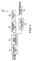
- the above-described signal processing device 10 can also be used, for example, in an image coding device 30 as shown in Fig.7 .
- the above-described signal processing device 10 is provided in the image coding device 30 and preprocessing to collectively code similar parts of plural images (including different partial images of one image) is performed in advance, thereby improving the coding efficiency (compression efficiency).
- the image coding device 30 has a similar area detecting unit 31, a similar component separating unit 32, a similar component coding unit 33, a similar component subtracting unit 34, an image coding unit 35, and an integrating unit 36.
- the similar area detecting unit 31 is equivalent to the above-described signal processing device 10.
- the similar area detecting unit 31 inputs a first image and a second image.
- the first image is shown on the left side and the second image is shown on the right side.
- the similar area detecting unit 31 detects whether the second image includes a part similar to a part of the first image or not. If the second image includes a similar part (YES) at step S41, the processing goes to step S42. If not, the processing goes to step S43.
- the similar component separating unit 32 extracts the position difference, luminance ratio and area shape of the similar area a, as shown in Fig.9A , and the similar component coding unit 33 codes these. Then, the processing returns to step S41 and another similar part is detected. Thus, a similar area b is detected as shown in Fig.9B and the position difference, luminance ratio and area shape of the similar area b are coded.
- the similar component subtracting unit 34 at step S43 subtracts the parts similar to those of the first image from the second image, as shown in Fig.9C .
- the image coding unit 35 codes the first image and the second image from which the similar parts have been subtracted.
- a typical image coding method such as a DCT (discrete cosine transform) method or a wavelet method can be used.
- the integrating unit 36 integrates the information of the position difference and the like of the similar areas coded at step S42 and the first and second images coded at step S44, as one code sequence, and outputs the code sequence. Then, the processing ends.
- the coding efficiency is the same as that of the typical coding method.
- the second image since the parts similar to those of the first image have been subtracted, the quantity of information is reduced. Therefore, the coding efficiency can be improved, compared with the case of using the ordinary coding method as it is.
- this technique of the image coding device 30 is applied to compression of a dynamic image including plural continuous images, it can be used as an effective motion vector detecting technique used in the compression system such as MPEG2 (Moving Picture Experts Group 2).
- MPEG2 Motion Picture Experts Group 2
- the signal processing device of this embodiment at least one of inputted plural image data is divided into small areas and the similarity of each of the small areas to the other image data is found and integrated to evaluate the overall similarity. Therefore, the similarity of arbitrary image data including a partially similar pattern, which cannot be detected by the conventional technique, can be evaluated, and the similar area can be extracted.
- this signal processing device is provided in a video/image search device, by designating a desired video or image of video data or image data that is being reproduced, video data or image data recorded in a recording medium or video data or image data acquired via a network can be searched for video data or image data having a pattern partly similar to the desired video or image.
- this signal processing device is provided in an image coding device and preprocessing to collectively code similar patterns is performed in advance, the coding efficiency can be improved.
- the present invention is not limited to this and can be applied to other types of similarity evaluation quantity.
- At least one of inputted plural image data is divided into small areas and the similarity of each of the small areas to the other image data is found and integrated to evaluate the overall similarity. Therefore, the similarity of arbitrary image data including a partially similar pattern, which cannot be detected by the conventional technique, can be evaluated, and the similar area can be extracted. Moreover, this can be used to search for video data or image data having a pattern partially similar to a desired video or image. Furthermore, as preprocessing to collectively code similar patterns is performed in advance, the coding efficiency can be improved.
Abstract
Description
- This invention relates to a signal processing method and device, a signal processing program, and a recording medium, and particularly to a signal processing method and device, a signal processing program, and a recording medium having a signal processing program recorded thereon for evaluating the similarity in the case where plural image data include a similar pattern.
- For example, partly identical or similar patterns such as images of similar scenes in a video (a collective time section in the video), a logo of a company name in a commercial, and a characters or pattern indicating an owner inserted in an image may be included in different images. In most cases, these similar patterns used because they are related to each image or video to a certain extent. If the similarity can be detected and evaluated, search for and classification or collection of related image or video scenes can be realized.
- As a specific example,
Figs. 1A and 1B show different images in which the same logo "ABE" is inserted. Such a logo represents, for example, information of an owner of the two images or an enterprise providing a product of a commercial image. As in this case, substantially the same logo may be inserted at different positions in the images. Usually, however, the positions where such a logo is inserted cannot be specified in advance and what pattern is inserted cannot be known in advance, either. - Not only a logo but also the same person, animal, object or background may be inserted in different images or videos.
- Meanwhile, as a conventional method for searching for such a similar pattern, the pattern is separately prepared in advance by a certain technique and the pattern id detected by a correlative method, a histogram comparison method or the like.
- For example, the Publication of Japanese Laid-Open Patent Application No.
2000-312343 - The Publication of Japanese Laid-Open Patent Application No.
H11-328311 -
US 5,406,642 A describes that, in a block matching method, a successive one of segmented blocks of a first image is superimposed on a portion of a second image, and a correlation is detected therebetween. The superimposed block is successively moved by a small amount and correlations are repeatedly detected for different locations of the successively moved block. A maximum value of the correlations is detected and a vector representing the location of the block of the maximum correlation is stored into a memory as a match between a block of the first image and a portion of the second image. The process is repeated for the remaining blocks of the first image to create a map of the matching vectors in the memory. Direction sensitivity functions and vector smoothing functions are derived from the segmented blocks for respectively correcting the stored matching vectors. -
US 4,677,476 A describes a method for detecting a movement of a television signal corresponding to the movement of a television camera during a panning operation includes dividing a picture plane of the television signal into blocks and obtaining an absolute value of a difference between pixel values from two consecutive frames for each block. The absolute value is integrated and a block matching table of frame difference integration data is derived therefrom. An extremum value of the frame difference integration data is linearly obtained from a maximum gradient of four gradients taken in upper, lower, left and right gradient directions from the respective origin of each block using the block matching table. This extremum value may be compared with frame difference integration data taken in four oblique directions intermediate the gradient directions to verify the extremum value. - The document "Robust Image Matching for Occlusion Using Vote by Block Matching" by F. Saitoh (Gifu Univ., Fac. of Eng.), published in IEICE Transactions on Information and Systems, Pt.2 (Japanese Edition), Vol. J84-D-2; no.10; pages 2270-2279, 2001, proposes an image template matching method, in which a template image is separated to local areas and normalized correlation matching is implemented in each block area. The method which accumulates the matching rate of all blocks and the method which votes to the address with the maximum matching rate are mentioned.
- In view of the foregoing status of the art, it is an object of the present invention to provide a signal processing method and device, a signal processing program, and a recording medium having a signal processing program recorded therein that enable evaluation of partial similarity of two or more arbitrary images and automatic extraction of a similar area.
- In order to achieve the above-described object a signal processing method is defined according claim 1. The device, program and recording medium are defined in
claims 13, 25 and 26, respectively. Further details are defined in the dependent claims. A signal processing method as an example useful for understanding the present invention includes: a division step of inputting plural image data and dividing at least one of the plural image data into plural small areas; a parameter extraction step of extracting a conversion parameter used for converting the small areas so that the small areas become similar to the other image data; a totaling step of totaling values indicating the degree of similarity found on the basis of the conversion parameter; and a similarity evaluation step of evaluating the similarity between the plural image data on the basis of the result of the totaling. - The signal processing method may further include a similar area extraction step of extracting a similar area of the plural image data.
- In the signal processing method, the conversion parameter may be found using a correlative method. In this case, the conversion parameter is, for example, a position difference and/or luminance ratio at a point where a maximum correlation value between the small area and the other image data is obtained, and at the totaling step, values indicating the degree of similarity between the plural image data are totaled in a space centering the conversion parameter as an axis.
- In such a signal processing method, at least one of inputted plural image data is divided into plural small areas and the similarity between each small area and the other image data is found. As these similarity values are totaled, the similarity between the plural image data is evaluated. On the basis of the similarity, a similar area of the plural image data may be extracted.
- Moreover, the signal processing method according to the present invention may includes: a reproduction step of reproducing image data recorded in recording means; a designation step of designating desired image data from the image data that are being reproduced; and a similar area detection step of detecting a similar area of the desired image data and search target image data of the image data.
- In such a signal processing method, when desired image data is designated from image data that are being reproduced, the image data is divided into small areas and the similarity between each small area and search target image data recorded in the recording means is found. As the similarity values are totaled, the similarity between the plural image data is evaluated and a similar area may be extracted on the basis of the similarity.
- Moreover, the signal processing method according to the present invention may include: a similar area extraction step of extracting a similar area of the plural image data; a first coding step of coding the similar area of the plural image data extracted at the similar area extraction step; and a second coding step of coding the areas other than the similar area.
- In this case, at the first coding step, for example, information of position difference of the similar area, luminance ratio, and shape of the similar area is coded.
- In such a signal processing method, at least one of inputted plural image data is divided into plural small areas and the similarity between each small area and the other image data is found. As the similarity values are totaled, the similarity between the plural image data is evaluated. On the basis of the similarity, a similar area of the plural image data may be extracted, and the similar area and the other areas may be separately coded.
- A signal processing device as an example useful for understanding the present invention includes: division means for inputting plural image data and dividing at least one of the plural image data into plural small areas; parameter extraction means for extracting a conversion parameter used for converting the small areas so that the small areas become similar to the other image data; totaling means for totaling values indicating the degree of similarity found on the basis of the conversion parameter; and similarity evaluation means for evaluating the similarity between the plural image data on the basis of the result of the totaling
- The signal processing device may further include similar area extraction means for extracting a similar area of the plural image data.
- In the signal precessing device, the conversion parameter may be found using a correlative method. In this case, the conversion parameter is, for example, a position difference and/or luminance ratio at a point where a maximum correlation value between the small area and the other image data is obtained, and at the totaling means totals values indicating the degree of similarity between the plural image data in a space centering the conversion parameter as an axis.
- In such a signal processing device, at least one of inputted plural image data is divided into plural small areas and the similarity between each small area and the other image data is found. As these similarity values are totaled, the similarity between the plural image data is evaluated. On the basis of the similarity, a similar area of the plural image data may be extracted.
- Moreover, the signal processing device according to the present invention may include: recording means for recording plural image data; reproduction means for reproducing the image data recorded in the recording means; designation means for designating desired image data from the image data that are being reproduced; and similar area detection means for detecting a similar area of the desired image data and the search target image data of the image data.
- In such a signal processing device, when desired image data is designated from image data that are being reproduced, the image data is divided into small areas and the similarity between each small area and search target image data recorded in the recording means is found. As the similarity values are totaled, the similarity between the plural image data is evaluated and a similar area may be extracted on the basis of the similarity.
- Moreover, the signal processing device according to the present invention may include: similar area extraction means for extracting a similar area of the plural image data; first coding means for coding the similar area of the plural image data extracted by the similar area extraction means; and second coding means for coding the areas other than the similar area.
- In this case, the first coding means codes, for example, information of position difference of the similar area, luminance ratio, and shape of the similar area.
- In such a signal processing device, at least one of inputted plural image data is divided into plural small areas and the similarity between each small area and the other image data is found. As the similarity values are totaled, the similarity between the plural image data is evaluated. On the basis of the similarity, a similar area of the plural image data may be extracted, and the similar area and the other areas may be separately coded.
- A signal processing program as an example useful for understanding the present invention includes:a division step of inputting plural image data and dividing at least one of the plural image data into plural small areas; a parameter extraction step of extracting a conversion parameter used for converting the small areas so that the small areas become similar to the other image data; a totaling step of totaling values indicating the degree of similarity found on the basis of the conversion parameter; and a similarity evaluation step of evaluating the similarity between the plural image data on the basis of the result of the totaling
- The signal processing program may further include a similar area extraction step of extracting a similar area of the plural image data.
- In the signal precessing program, the conversion parameter may be found using a correlative method. In this case, the conversion parameter is, for example, a position difference and/or luminance ratio at a point where a maximum correlation value between the small area and the other image data is obtained, and at the totaling step, values indicating the degree of similarity between the plural image data are totaled in a space centering the conversion parameter as an axis.
- In such a signal processing program, at least one of inputted plural image data is divided into plural small areas and the similarity between each small area and the other image data is found. As these similarity values are totaled, the similarity between the plural image data is evaluated. On the basis of the similarity, a similar area of the plural image data may be extracted.
- Moreover, the signal processing program according to the present invention may include: a reproduction step of reproducing image data recorded in recording means; a designation step of designating desired image data from the image data that are being reproduced; and a similar area detection step of detecting a similar area of the desired image data and the search target image data of the image data.
- In such a signal processing program, when desired image data is designated from image data that are being reproduced, the image data is divided into small areas and the similarity between each small area and search target image data recorded in the recording means is found. As the similarity values are totaled, the similarity between the plural image data is evaluated and a similar area may be extracted on the basis of the similarity.
- Moreover, the signal processing program according to the present invention may include: a similar area extraction step of extracting a similar area of the plural image data; a first coding step of coding the similar area of the plural image data extracted at the similar area extraction step; and a second coding step of coding the areas other than the similar area.
- In this case, at the first coding step, for example, information of position difference of the similar area, luminance ratio, and shape of the similar area is coded.
- In such a signal processing program, at least one of inputted plural image data is divided into plural small areas and the similarity between each small area and the other image data is found. As the similarity values are totaled, the similarity between the plural image data is evaluated. On the basis of the similarity, a similar area of the plural image data may be extracted, and the similar area and the other areas may be separately coded.
- A recording medium as an example useful for understanding the present invention is a computer-controllable recording medium having a signal processing program recorded therein, the signal processing program including: a division step of inputting plural image data and dividing at least one of the plural image data into plural small areas; a parameter extraction step of extracting a conversion parameter used for converting the small areas so that the small areas become similar to the other image data; a totaling step of totaling values indicating the degree of similarity found on the basis of the conversion parameter; and a similarity evaluation step of evaluating the similarity between the plural image data on the basis of the result of the totaling
- The signal processing program may further include a similar area extraction step of extracting a similar area of the plural image data.
- In the signal precessing program, the conversion parameter may be found using a correlative method. In this case, the conversion parameter is, for example, a position difference and/or luminance ratio at a point where a maximum correlation value between the small area and the other image data is obtained, and at the totaling step, values indicating the degree of similarity between the plural image data are totaled in a space centering the conversion parameter as an axis.
- In the signal processing program recorded in such a recording medium, at least one of inputted plural image data is divided into plural small areas and the similarity between each small area and the other image data is found. As these similarity values are totaled, the similarity between the plural image data is evaluated. On the basis of the similarity, a similar area of the plural image data may be extracted.
- Moreover, the recording medium according to the present invention is a computer-controllable recording medium having a signal processingprogram recorded therein, the signal processing program may include: a reproduction step of reproducing image data recorded in recording means; a designation step of designating desired image data from the image data that are being reproduced; and a similar area detection step of detecting a similar area of the desired image data and the search target image data of the image data.
- In the signal processing program recorded in such a recording medium, when desired image data is designated from image data that are being reproduced, the image data is divided into small areas and the similarity between each small area and search target image data recorded in the recording means is found. As the similarity values are totaled, the similarity between the plural image data is evaluated and a similar area may be extracted on the basis of the similarity.
- Moreover, the recording medium according to the present invention is a computer-controllable recording medium having a signal processing program recorded therein, the signal processing program may be include: a similar area extraction step of extracting a similar area of the plural image data; a first coding step of coding the similar area of the plural image data extracted at the similar area extraction step; and a second coding step of coding the areas other than the similar area.
- In this case, at the first coding step of the signal processing program, for example, information of position difference of the similar area, luminance ratio, and shape of the similar area is coded.
- In the signal processing program recorded in such a recording medium, at least one of inputted plural image data is divided into plural small areas and the similarity between each small area and the other image data is found. As the similarity values are totaled, the similarity between the plural image data is evaluated. On the basis of the similarity, a similar area of the plural image data may be extracted, and the similar area and the other areas may be separately coded.
- The other objects of the present invention and specific advantages provided by the present invention will be further clarified by the following description of an embodiment.
-
-
Figs.1A and 1B are views for explaining exemplary images including the same logo. -
Fig.2 is a view for explaining the schematic structure of a signal processing device of this embodiment. -
Figs.3A to 3C are views for explaining the operation of the signal processing device.Fig.3A shows division of a first image into small areas.Fig.3B shows detection of a similar area in a second image using a correlative method.Fig.3C shows voting for a parameter of that area in a voting space. -
Fig.4 is a flowchart for explaining the operation of the signal processing device. -
Fig.5 is a view for explaining the schematic structure of a video/image search device to which the signal precessing device is applied. -
Fig.6 is a flowchart for explaining the operation of the video/image search device. -
Fig.7 is a view for explaining the schematic structure of an image coding device using the signal processing device. -
Fig.8 is a flowchart for explaining the operation of the image coding device. -
Figs.9A to 9C are views for explaining the operation of the image coding device.Fig.9A shows detection of a similar area a.Fig.9B shows detection of a similar area b.Fig.9C shows subtraction of the similar areas from a second image. - A specific embodiment to which the present invention is applied will now be described in detail with reference to the drawings. In this embodiment, the present invention is applied to a signal processing device which evaluates partial similarity of two or more arbitrary images and automatically extracts a similar area. In the following description, two different images are used inputted images. However, two or more images may be used or plural images acquired from video data or plural partial images acquired from one image may also be used.
- First,
Fig.2 shows the schematic structure of a signal processing device of this embodiment. As shown inFig.2 , asignal processing device 10 has afirst preprocessing unit 11, anarea dividing unit 12, asecond preprocessing unit 13, asimilarity calculating unit 14, avoting unit 15, asimilarity judging unit 16, and a similararea detecting unit 17. - The
first preprocessing unit 11 performs, to a first image of the two images to be compared, known filter processing for extracting image characteristics such as differentiation or high-order differentiation, known transform processing such as color-reducing arithmetic operation, monochromatization or binarization processing, and processing to limit the subsequent processing range on the basis of the characteristic quantity of edge detection, edge density detection, local color histogram or the like. Preprocessing of a combination of the above-described processing may be performed. Alternatively, identical transform may be performed without performing any processing. - The
area dividing unit 12 divides the first image into small areas. For example, as shown inFig.3A , thearea dividing unit 12 divides the first image into 63 small areas. Of course, the number of divisions is not limited to this and can be arbitrarily set. However, it is preferred that the size of a small area is set to be much smaller than that of an anticipated similar area. For example, in the above-described example ofFigs.1A and 1B , it is preferred that the logo "ABE" is set to be divided into at least plural areas. While the small areas inFig.3A are divided in such a manner that they do not overlap each other, the small areas may overlap each other. - The
second preprocessing unit 13 performs preprocessing similar to that of thefirst preprocessing unit 11, to a second image of the two images to be compared. Alternatively, identical transform may be performed without performing any processing, as in the case of the first image. - The
similarity calculating unit 14 calculates the correlation between each of the small areas provided by division at thearea dividing unit 12 and the second image. Normally, to calculate the correlation, correlation operation is performed for the entire range of the second image using each of the small areas as template, as shown inFig.3B . Thesimilarity calculating unit 14 searches for a small area having the largest correlation value of the resulting correlation values, and acquires the correlative value s, position difference dx, dy, and luminance ratio 1. The position difference is a parameter indicating the relative positional relation between the original position of this small area in the first image and the position where the maximum correlation value is obtained. The luminance ratio is a multiplication coefficient for the patter of the small area pattern such that the pattern of the small area and the pattern of the second image are most coincident with each other at the position where the maximum correlation value is obtained. For example, when the luminance of the overall image differs because of the difference in conditions, for example, fluctuation of video data, at the time of acquiring the first image and the second image, that difference becomes the coefficient. As the similarity, the square of the correlation value may be used. For the above-described position difference dx, dy, luminance ratio I and similarity s, equivalent characteristic quantities may also be found using a method other than the correlative method. - The
voting unit 15 votes the acquired position difference dx, dy, luminance ratio I and similarity s into a voting space. The voting space is a feature space using the position difference dx, dy and luminance ratio I as variables and using an integral value of the similarity s as a value, as shown inFig.3C . The similarity s is integrated at a position having the position difference dx, dy and the luminance ratio 1 acquired from the small area. Although the position difference dx, dy is shown on a single axis inFig.3C , a typical image has two axes in horizontal and vertical directions and therefore has three variables in the voting space. To improve the operation efficiency, one of the axes may be omitted to reduce the number of dimensions. - When the first signal and the second signal include a similar part, the patterns of the corresponding small areas are similar to each other. Therefore, the similarity s is high and the position difference dx, dy and the luminance ratio I are approximately coincident with those of the other small areas.
- On the other hand, with respect to a small area corresponding to a part that is not similar, the maximum similarity is acquired at a position that is accidentally most similar. Therefore, the overall similarity s is low and the position difference dx, dy and the luminance ratio I are independent of those of the other small areas.
- Therefore, when a similar part exists, voting of plural small areas corresponding to this part concentrates at the same position and a significantly large peak is expected to be formed. When no similar part exists, the similarity is essentially low and voting is dispersed at different positions. Therefore, no significant peak is formed.
- Thus, after voting for all the small areas is performed, the
similarity judging unit 16 searches for the maximum similarity sm in the voting space and compares the maximum similarity sm with a threshold value sthsd, thereby judging the similarity. - When the
similarity judging unit 16 judges that the similarity is high, the similararea detecting unit 17 detects a similar area. The similararea detecting unit 17 detects a similar area, for example, by selecting only a small area where the position difference dx, dy and the luminance ratio I are sufficiently close to the position difference dxm ,dym and the luminance ratio Im of the peak position. - The operation of the
signal processing device 10 having the above-described structure will now be described with reference to the flowchart ofFig.4 . First at step S10, the preprocessing as described above is performed to the first image and the second image. - At the next step S11, the first image is divided into small areas as described above, and at the next step S12, one of the small areas is selected.
- At step S13, the correlation between the small area selected at step S12 and the second image is calculated. For example, the correlative method is used for the entire range of the second image with respect to the selected small area, thus calculating the correlation between the small area and the second image.
- At step S14, the largest value of the similarity obtained at step S13 is found and the similarity s, the position difference dx, dy and the luminance ratio I are acquired.
- At the next step S15, the similarity s, the position difference dx, dy and the luminance ratio 1 acquired at step S14 are voted in the voting space. That is, the similarity s is integrated at the position having the position difference dx, dy and the luminance ratio 1 acquired from the small area.
- At step S16, whether processing is completed for all the small areas or not is judged. If there still is a small area for which processing is not completed at step S16, the processing returns to step S12 and the above-described processing is repeated for the remaining small area. If processing is completed for all the small areas, the processing goes to step S17.
- At step S17, the maximum similarity sm in the voting space is searched for and acquired. At the next step S18, whether the maximum similarity sm exceeds a predetermined threshold value sthsd or not is judged. If the maximum similarity sm does not exceed the predetermined threshold value sthsd (NO) at step S18, it is assumed that no significant peak is formed and the processing goes to step S21. Then, it is judged that the first image and the second image are not similar to each other, and the processing ends. If the maximum similarity sm exceeds the predetermined threshold value sthsd (YES) at step S18, it is assumed that a significant peak is formed and the processing goes to step S19.
- At step S19, it is judged that the first image and the second image are similar to each other, and the position difference dxm, dym and the luminance ratio Im are acquired. The similarity between the first image and the second image is assumed to be the maximum similarity sm.
- At step S20, a similar area is detected. Specifically, only a small area having the position difference dx, dy and the luminance ratio 1 that are sufficiently close to the position difference dxm, dym and the luminance ratio Im of the peak position is selected, and the processing ends.
- By carrying out the processing as described above, the
signal processing device 10 of this embodiment perform detection and evaluation of significant similarity or non-similarity between two arbitrary images from which a similar pattern is not found in advance. - Moreover, as described above, the
signal processing device 10 can detect similar areas by selecting only a small area having the position difference dx, dy and the luminance ratio I that are sufficiently close to the position difference dxm, dym and the luminance ratio Im of the peak position. - In the above description, the similarity s, the position difference dx, dy and the luminance ratio 1 at one position having the highest correlation with the second image are acquired for each small area and voting is then performed. However, the processing is not limited to this and the similarity s, the position difference dx, dy and the luminance ratio 1 at several positions having high correlation may be acquired and voting may be then performed.
- In the above description, only the maximum similarity sm at the peak position in the voting space is compared with the threshold value sthsd, and if it exceeds the threshold value sthsd, the small area on which voting is performed for that peak is found. However, the processing is not limited to this, and even when the second image includes plural parts similar to those of the first image, all these similar parts can be extracted.
- The above-described
signal processing device 10 can be used, for example in a video/image search device 20 as shown inFig.5 . This video/image search device 20 is adapted for searching a recorded video or image for a similar part. - As shown in
Fig.5 , the video/image search device 20 has arecording unit 21, a reproducing/display unit 22, aninput unit 23, and asimilarity search unit 24. Thesimilarity search unit 24 is equivalent to the above-describedsignal processing device 10. - The operation of the video/
image search device 20 having such a structure will now be described with reference to the flowchart ofFig.6 . In therecording unit 21, video data and image data are recorded. First at step S30, a user reproduces a signal recorded in therecording unit 21 or a signal that is being broadcast in real time, using the reproducing/display unit 22. - At the next step S31, the user designates an image or frame to be retrieved from the signal via the
input unit 23. Thesimilarity search unit 24 is notified of the designated image. - At the next step S32, the
similarity search unit 24 searches search target data recorded in therecording unit 21 to find video data or image data having a similar part. - Video data or image data as a search target is not limited to data recorded in advance in a magnetic recording medium or the like, and may be a signal that is being broadcast in real time or a signal acquired via a network. In the case of a real-time broadcast signal, the
similarity search unit 24 waits for video data or image data having a similar part while receiving the signal. - When a similar part is found, this similar part is displayed on the reproducing/
display unit 22 at step S33 and the processing ends. - In the above-described example, the user designates an image or frame to be retrieved from video data or image data that is being reproduced. However, the operation is not limited to this. For example, the user may designate a file name of video data or image data, and search for video data or image data similar to the video data or image data of the designated file name may be performed. Moreover, though the user directly designates an image or frame to be retrieved in the above-described example, the operation is not limited to this and an image or frame may be designated, for example, via an interface with another device.
- With such a video/
image search device 20, for example, if the user designates a commercial part of a broadcast, highly related commercials such as commercials provided by the same company may be searched because such highly related commercials usually include a similar part. Moreover, when video data or image data designated by the user is commonly used for similar broadcast programs, such similar broadcast programs may be searched. - The above-described
signal processing device 10 can also be used, for example, in animage coding device 30 as shown inFig.7 . Specifically, the above-describedsignal processing device 10 is provided in theimage coding device 30 and preprocessing to collectively code similar parts of plural images (including different partial images of one image) is performed in advance, thereby improving the coding efficiency (compression efficiency). - As shown in
Fig.7 , theimage coding device 30 has a similararea detecting unit 31, a similarcomponent separating unit 32, a similarcomponent coding unit 33, a similarcomponent subtracting unit 34, animage coding unit 35, and an integratingunit 36. The similararea detecting unit 31 is equivalent to the above-describedsignal processing device 10. - The operation of the
image coding device 30 having such a structure will now be described with reference to the flowchart ofFig.8 andFigs.9A to 9C . First at step S40, the similararea detecting unit 31 inputs a first image and a second image. InFigs.9A and 9B , the first image is shown on the left side and the second image is shown on the right side. - At the next step S41, the similar
area detecting unit 31 detects whether the second image includes a part similar to a part of the first image or not. If the second image includes a similar part (YES) at step S41, the processing goes to step S42. If not, the processing goes to step S43. - At step S42, the similar
component separating unit 32 extracts the position difference, luminance ratio and area shape of the similar area a, as shown inFig.9A , and the similarcomponent coding unit 33 codes these. Then, the processing returns to step S41 and another similar part is detected. Thus, a similar area b is detected as shown inFig.9B and the position difference, luminance ratio and area shape of the similar area b are coded. - After all similar sections are extracted and coded, the similar
component subtracting unit 34 at step S43 subtracts the parts similar to those of the first image from the second image, as shown inFig.9C . - At step S44, the
image coding unit 35 codes the first image and the second image from which the similar parts have been subtracted. For this coding, a typical image coding method such as a DCT (discrete cosine transform) method or a wavelet method can be used. - At step S45, the integrating
unit 36 integrates the information of the position difference and the like of the similar areas coded at step S42 and the first and second images coded at step S44, as one code sequence, and outputs the code sequence. Then, the processing ends. - With this
image coding device 30, since a general coding method is directly applied to the first image, the coding efficiency is the same as that of the typical coding method. As for the second image, however, since the parts similar to those of the first image have been subtracted, the quantity of information is reduced. Therefore, the coding efficiency can be improved, compared with the case of using the ordinary coding method as it is. - As this technique of the
image coding device 30 is applied to compression of a dynamic image including plural continuous images, it can be used as an effective motion vector detecting technique used in the compression system such as MPEG2 (Moving Picture Experts Group 2). - As described above, in the signal processing device of this embodiment, at least one of inputted plural image data is divided into small areas and the similarity of each of the small areas to the other image data is found and integrated to evaluate the overall similarity. Therefore, the similarity of arbitrary image data including a partially similar pattern, which cannot be detected by the conventional technique, can be evaluated, and the similar area can be extracted.
- Moreover, as this signal processing device is provided in a video/image search device, by designating a desired video or image of video data or image data that is being reproduced, video data or image data recorded in a recording medium or video data or image data acquired via a network can be searched for video data or image data having a pattern partly similar to the desired video or image.
- Furthermore, as this signal processing device is provided in an image coding device and preprocessing to collectively code similar patterns is performed in advance, the coding efficiency can be improved.
- The present invention is not limited to the above-described embodiment and various modifications can be made without departing from the scope of the invention.
- For example, while the technique of minimizing the secondary error energy, which is the most common similarity evaluation quantity, is used, that is, the correlative method is used in evaluating the similarity in the above description, the present invention is not limited to this and can be applied to other types of similarity evaluation quantity.
- According to the present invention, at least one of inputted plural image data is divided into small areas and the similarity of each of the small areas to the other image data is found and integrated to evaluate the overall similarity. Therefore, the similarity of arbitrary image data including a partially similar pattern, which cannot be detected by the conventional technique, can be evaluated, and the similar area can be extracted. Moreover, this can be used to search for video data or image data having a pattern partially similar to a desired video or image. Furthermore, as preprocessing to collectively code similar patterns is performed in advance, the coding efficiency can be improved.
Claims (26)
- A signal processing method comprising:providing (S40) at least a first and a second image;dividing (S11) the first image into a plurality of small areas;determining a plurality of conversions for a respective small area based on a conversion parameter, the conversion parameter resulting in a different position, wherein each conversion is determined based on a certain value of the conversion parameter;calculating (S13) for the plurality of conversions a plurality of similarity values, wherein a respective similarity value is descriptive of the similarity between the respective converted small area and the second image;determining (S14), for each small area, the respective maximum similarity value out of the plurality of similarity values and the corresponding value of the conversion parameter which was used for the conversion leading to the respective maximum similarity value; andcharacterized by
totaling (S15) the maximum similarity values of the plurality of small areas for each certain value of the conversion parameter;
evaluating (S19) the similarity between the first and second images on the basis of the result of the totaling. - The signal processing method as claimed in claim 1, further comprising a similar area extraction step (S42) of extracting a similar area of the first image and second image, wherein at the similar area extraction step, a small area is extracted for which a conversion parameter corresponding to the maximum similarity value is substantially equal to the conversion parameter of a point where the result of the totaling reaches its maximum as the similar area .
- The signal processing method as claimed in claim 1, wherein the similarity values are found using a correlative method.
- The signal processing method as claimed in claim 3, wherein
the conversion comprises further change of luminance value, and the value of the conversion parameter which was used for the conversion leading to the respective maximum similarity value is a position difference and luminance ratio. - The signal processing method as claimed in claim 1, wherein at the totaling step (S15), values indicating the degree of similarity between the first and the second image are totaled in a space having the conversion parameter as an axis.
- The signal processing method as claimed in claim 1, wherein the similarity values are values proportional to the similarity between the respective controlled small areas of the first image and the second image.
- The signal processing method as claimed in claim 6. wherein a correlation value or the square of the correlation value is used as the similarity value.
- The signal processing method as claimed in claim 1, wherein the first image and the second image are different partial image data of one image .
- A signal processing method as claimed in claim 1, further comprising:a reproduction step (S30) of reproducing image data recorded in recording means (21);a designation step (S31) of designating desired image data from the image data that are being reproduced as the first image and search target image data recorded in the recording means as second image; anda similar area detection step of detecting a similar area of the desired image data and the search target image data, by detecting a small area for which a conversion parameter corresponding to the maximum similarity value is substantially equal to the conversion parameter of a point where the result of the totaling reaches its maximum.
- The signal processing method as claimed in claim 9, wherein the search target image data is acquired from a network or a broadcast signal.
- A signal processing method as claimed in claim 2, further comprising:a first coding step of coding the similar area of the first image and second image extracted at the similar area extraction step; anda second coding (S44) step of coding the areas other than the similar area.
- The signal processing method as claimed in claim 11, wherein at the first coding step, information of position difference of the similar area, luminance ratio, and shape of the similar area is coded.
- A signal processing device(10, 20. 30) comprising:division means (12) for inputting at least a first and a second image and dividing the first image data into a plurality of small areas; andparameter extraction means (14) for determining a plurality of conversions for a respective small area based on a conversion parameter, the conversion parameter resulting in a different position, wherein each conversion is determined based on a certain value of the conversion parameter, and for calculating for the plurality of conversions a plurality of similarity values, wherein a respective similarity value is descriptive of the similarity between the respective converted small area and the second image, and for determining, for each small area, the respective maximum similarity value out of the plurality of similarity values and the corresponding value of the conversion parameter which was used for the conversion leading to the respective maximum similarity value;characterized by
totaling means (15) for totaling the maximum similarity values of the plurality of small areas for each certain value of the conversion parameter; and
similarity evaluation means (16) for evaluating the similarity between the first and second image on the basis of the result of the totaling. - The signal processing device as claimed in claim 13, further comprising similar area extraction means (32) for extracting a similar area of the first image and the second image wherein the similar area extraction means (32) extracts a small area, for which a conversion parameter corresponding to the maximum similarity value is substantially equal to the conversion parameter of a point where the result of the totaling reaches its maximum similarity value as the similar, area.
- The signal processing device as claimed in claim 13, wherein the similarity values are found using a correlative method.
- The signal processing device as claimed in claim 15, wherein
the conversion comprises further change of luminance value, and
the value of the conversion parameter which was used for the conversion leading to the respective maximum similarity value is a position difference and/or luminance ratio. - The signal processing device as claimed in claim 13. wherein the totaling means totals values indicating the degree of similarity between the first and the second image in a space having the conversion parameter as an axis.
- The signal processing device as claimed in claim 13. wherein the similarity values are values proportional to the similarity between the respective concentrated small area of the first image and the second image.
- The signal processing device as claimed in claim 18. wherein a correlation value or the square of the correlation value is used as the similarity value.
- The signal processing device as claimed in claim 13, wherein the first image and the second image are different partial image data of one image.
- A signal processing device as claimed in claim 13. further comprising:recording means (21) for recording plural image data;reproduction means (22) for reproducing the image data recorded in the recording means (21);designation means for designating desired image data from the image data that are being reproduced as first image and search target image data recorded in the recording means (21) as the second image; andsimilar area detection means for detecting a similar area of the desired image data and the search target image data, by selecting a small area for which a conversion parameter corresponding to the maximum similarity value is substantially equal to the conversion parameter of a point where the result of the totaling reaches its maximum similarity value.
- The signal processing device as claimed in claim 21, wherein the search target image data is acquired from a network or a broadcast signal.
- A signal processing device as claimed in claim 14, further comprising:first coding means (33) for coding the similar area of the first and the second image extracted by the similar area extraction means; andsecond coding means (35) for coding the areas other than the similar area.
- The signal processing device as claimed in claim 23. wherein the first coding means (33) codes information of position difference of the similar area, luminance ratio, and shape of the similar area.
- A signal processing program for executing a method according to claims 1 to 12.
- A computer-controllable recording medium having a signal processing program recorded therein according to claim 25.
Applications Claiming Priority (3)
| Application Number | Priority Date | Filing Date | Title |
|---|---|---|---|
| JP2001324255A JP3997749B2 (en) | 2001-10-22 | 2001-10-22 | Signal processing method and apparatus, signal processing program, and recording medium |
| JP2001324255 | 2001-10-22 | ||
| PCT/JP2002/010749 WO2003036563A1 (en) | 2001-10-22 | 2002-10-16 | Signal processing method and processor |
Publications (3)
| Publication Number | Publication Date |
|---|---|
| EP1439491A1 EP1439491A1 (en) | 2004-07-21 |
| EP1439491A4 EP1439491A4 (en) | 2008-01-23 |
| EP1439491B1 true EP1439491B1 (en) | 2011-03-30 |
Family
ID=19141005
Family Applications (1)
| Application Number | Title | Priority Date | Filing Date |
|---|---|---|---|
| EP02802019A Expired - Fee Related EP1439491B1 (en) | 2001-10-22 | 2002-10-16 | Signal processing method and processor |
Country Status (6)
| Country | Link |
|---|---|
| US (1) | US7729545B2 (en) |
| EP (1) | EP1439491B1 (en) |
| JP (1) | JP3997749B2 (en) |
| CN (1) | CN100365661C (en) |
| DE (1) | DE60239627D1 (en) |
| WO (1) | WO2003036563A1 (en) |
Families Citing this family (24)
| Publication number | Priority date | Publication date | Assignee | Title |
|---|---|---|---|---|
| JP4255239B2 (en) * | 2002-03-29 | 2009-04-15 | 富士通株式会社 | Document search method |
| CN101110101A (en) * | 2006-07-17 | 2008-01-23 | 松下电器产业株式会社 | Method for recognizing picture pattern and equipment thereof |
| CN102156869B (en) * | 2006-07-17 | 2012-10-17 | 松下电器产业株式会社 | Method and device for detecting shapes formed by combining arbitrary line segments |
| US8107728B2 (en) | 2006-09-19 | 2012-01-31 | Sharp Kabushiki Kaisha | Image processing apparatus, image forming apparatus, image processing system, computer program and recording medium |
| JP4543067B2 (en) * | 2006-09-19 | 2010-09-15 | シャープ株式会社 | Image processing apparatus, image forming apparatus, image reading apparatus, image processing system, image processing method, computer program, and recording medium |
| JP5004743B2 (en) * | 2007-10-10 | 2012-08-22 | 東芝情報システム株式会社 | Data processing device |
| EP3239919A1 (en) | 2008-03-05 | 2017-11-01 | eBay Inc. | Method and apparatus for image recognition services |
| US9495386B2 (en) | 2008-03-05 | 2016-11-15 | Ebay Inc. | Identification of items depicted in images |
| US8086502B2 (en) | 2008-03-31 | 2011-12-27 | Ebay Inc. | Method and system for mobile publication |
| US7991646B2 (en) | 2008-10-30 | 2011-08-02 | Ebay Inc. | Systems and methods for marketplace listings using a camera enabled mobile device |
| US8825660B2 (en) * | 2009-03-17 | 2014-09-02 | Ebay Inc. | Image-based indexing in a network-based marketplace |
| US9164577B2 (en) | 2009-12-22 | 2015-10-20 | Ebay Inc. | Augmented reality system, method, and apparatus for displaying an item image in a contextual environment |
| EP2407928A1 (en) * | 2010-07-16 | 2012-01-18 | STMicroelectronics (Grenoble 2) SAS | Fidelity measurement of digital images |
| US10127606B2 (en) | 2010-10-13 | 2018-11-13 | Ebay Inc. | Augmented reality system and method for visualizing an item |
| JP2012133679A (en) * | 2010-12-22 | 2012-07-12 | Fujitsu Ltd | Image collation program, image collation method, and image collation device |
| US9449342B2 (en) | 2011-10-27 | 2016-09-20 | Ebay Inc. | System and method for visualization of items in an environment using augmented reality |
| US9240059B2 (en) | 2011-12-29 | 2016-01-19 | Ebay Inc. | Personal augmented reality |
| US9934522B2 (en) | 2012-03-22 | 2018-04-03 | Ebay Inc. | Systems and methods for batch- listing items stored offline on a mobile device |
| US10846766B2 (en) | 2012-06-29 | 2020-11-24 | Ebay Inc. | Contextual menus based on image recognition |
| KR101569622B1 (en) * | 2014-05-14 | 2015-11-16 | 엘에스산전 주식회사 | Converter and operating method thereof |
| KR101858829B1 (en) * | 2016-09-12 | 2018-05-18 | 주식회사 포스코 | Segregation analysis apparatus and method |
| JP7010004B2 (en) * | 2018-01-10 | 2022-01-26 | 京セラドキュメントソリューションズ株式会社 | Surveillance system and imaging device |
| KR102541500B1 (en) * | 2022-11-14 | 2023-06-13 | (주)오로스테크놀로지 | System for centering position of overlay key based on correlation and method thereof |
| KR102560241B1 (en) * | 2022-11-14 | 2023-07-28 | (주)오로스테크놀로지 | System for centering position of overlay key based on deep learning and method thereof |
Family Cites Families (37)
| Publication number | Priority date | Publication date | Assignee | Title |
|---|---|---|---|---|
| US3713100B2 (en) * | 1953-02-10 | 1991-05-07 | Method and apparatus for identifying letters,characters,symbols,and the like | |
| US3576534A (en) * | 1969-08-11 | 1971-04-27 | Compuscan Inc | Image cross correlator |
| JPS5214112B2 (en) * | 1973-02-22 | 1977-04-19 | ||
| US4110737A (en) * | 1977-08-22 | 1978-08-29 | The Singer Company | Character recognition apparatus for serially comparing an unknown character with a plurality of reference characters |
| US4736437A (en) * | 1982-11-22 | 1988-04-05 | View Engineering, Inc. | High speed pattern recognizer |
| JPH07118784B2 (en) | 1984-10-27 | 1995-12-18 | ソニー株式会社 | Method for detecting motion of television signals |
| JPH082106B2 (en) | 1986-11-10 | 1996-01-10 | 国際電信電話株式会社 | Hybrid coding method for moving image signals |
| US5406642A (en) * | 1988-12-23 | 1995-04-11 | Nec Corporation | Image matching method using direction sensitivity and vector smoothing functions for correcting matches |
| JP2941846B2 (en) | 1989-05-26 | 1999-08-30 | キヤノン株式会社 | Encoding and decoding device |
| JPH03260782A (en) * | 1990-03-09 | 1991-11-20 | Eastman Kodak Japan Kk | Pattern recognition device |
| JP3373008B2 (en) * | 1993-10-20 | 2003-02-04 | オリンパス光学工業株式会社 | Image area separation device |
| JPH0879760A (en) | 1994-09-05 | 1996-03-22 | Oki Electric Ind Co Ltd | Moving vector detection circuit |
| KR0154921B1 (en) * | 1994-12-30 | 1998-11-16 | 배순훈 | Motion estimation device of video encoding apparatus |
| JP2778567B2 (en) | 1995-12-23 | 1998-07-23 | 日本電気株式会社 | Signal encoding apparatus and method |
| US5809171A (en) * | 1996-01-05 | 1998-09-15 | Mcdonnell Douglas Corporation | Image processing method and apparatus for correlating a test image with a template |
| US5809717A (en) * | 1996-02-15 | 1998-09-22 | Sequoyah Exo Systems, Inc. | Apparatus and method for assembling composite building panels |
| US5845241A (en) | 1996-09-04 | 1998-12-01 | Hughes Electronics Corporation | High-accuracy, low-distortion time-frequency analysis of signals using rotated-window spectrograms |
| EP0869445A3 (en) * | 1997-03-31 | 2002-11-06 | Hitachi, Ltd. | Video signal processing system and method using time code |
| JPH10336593A (en) | 1997-03-31 | 1998-12-18 | Hitachi Ltd | Synchronous video processing system and method |
| KR100234264B1 (en) * | 1997-04-15 | 1999-12-15 | 윤종용 | Block matching method using moving target window |
| JP3242864B2 (en) | 1997-06-12 | 2001-12-25 | アロカ株式会社 | Ultrasonic diagnostic apparatus and ultrasonic transmitting / receiving method for ultrasonic diagnostic |
| US6038069A (en) | 1997-06-18 | 2000-03-14 | Konica Corporation | Real image type zoom finder |
| JPH11328311A (en) | 1997-08-06 | 1999-11-30 | Nippon Telegr & Teleph Corp <Ntt> | Method for extracting pattern in image, method for recognizing pattern in image, method for deciding image abnormality, and storage medium |
| US6438165B2 (en) * | 1998-03-09 | 2002-08-20 | Lg Electronics | Method and apparatus for advanced encoder system |
| JP3065314B1 (en) | 1998-06-01 | 2000-07-17 | 日本電信電話株式会社 | High-speed signal search method and apparatus and recording medium thereof |
| JP4057147B2 (en) * | 1998-06-16 | 2008-03-05 | コニカミノルタビジネステクノロジーズ株式会社 | Backlight scene determination method, computer-readable storage medium storing a backlight scene determination method program, and image processing apparatus having a backlight scene determination function |
| EP0973336A2 (en) * | 1998-07-15 | 2000-01-19 | Sony Corporation | Motion vector detecting, picture encoding and recording method and apparatus |
| JP2000078589A (en) | 1998-08-27 | 2000-03-14 | Sony Corp | Method for calculating movement vector and storage medium for recording movement vector calculating program |
| US6226606B1 (en) | 1998-11-24 | 2001-05-01 | Microsoft Corporation | Method and apparatus for pitch tracking |
| AU1930700A (en) * | 1998-12-04 | 2000-06-26 | Interval Research Corporation | Background estimation and segmentation based on range and color |
| US6330428B1 (en) | 1998-12-23 | 2001-12-11 | Nortel Networks Limited | Voice quality performance evaluator and method of operation in conjunction with a communication network |
| US6625216B1 (en) * | 1999-01-27 | 2003-09-23 | Matsushita Electic Industrial Co., Ltd. | Motion estimation using orthogonal transform-domain block matching |
| JP2001016447A (en) * | 1999-06-30 | 2001-01-19 | Minolta Co Ltd | Picture processor, picture processing method and recording medium with picture processing program stored therein |
| JP2001228900A (en) | 1999-12-10 | 2001-08-24 | Ricoh Co Ltd | Speech parameter encoding device, encoding system used for the same, computer-readable recording medium stated having encoding algorithm for the same, speech parameter quantizing device, quantization method used for this device and computer-readable recording medium loaded with quantization algorithm |
| JP3742279B2 (en) * | 2000-06-09 | 2006-02-01 | 日本電信電話株式会社 | Image collation apparatus, image collation method, and recording medium recording image collation program |
| US6859552B2 (en) * | 2000-11-07 | 2005-02-22 | Minolta Co., Ltd. | Image retrieving apparatus |
| US6907367B2 (en) | 2001-08-31 | 2005-06-14 | The United States Of America As Represented By The Secretary Of The Navy | Time-series segmentation |
-
2001
- 2001-10-22 JP JP2001324255A patent/JP3997749B2/en not_active Expired - Fee Related
-
2002
- 2002-10-16 EP EP02802019A patent/EP1439491B1/en not_active Expired - Fee Related
- 2002-10-16 CN CNB028032691A patent/CN100365661C/en not_active Expired - Fee Related
- 2002-10-16 DE DE60239627T patent/DE60239627D1/en not_active Expired - Lifetime
- 2002-10-16 WO PCT/JP2002/010749 patent/WO2003036563A1/en active Application Filing
- 2002-10-16 US US10/451,360 patent/US7729545B2/en not_active Expired - Fee Related
Also Published As
| Publication number | Publication date |
|---|---|
| JP3997749B2 (en) | 2007-10-24 |
| US7729545B2 (en) | 2010-06-01 |
| JP2003132354A (en) | 2003-05-09 |
| CN1479910A (en) | 2004-03-03 |
| WO2003036563A1 (en) | 2003-05-01 |
| US20040057627A1 (en) | 2004-03-25 |
| EP1439491A1 (en) | 2004-07-21 |
| DE60239627D1 (en) | 2011-05-12 |
| EP1439491A4 (en) | 2008-01-23 |
| CN100365661C (en) | 2008-01-30 |
Similar Documents
| Publication | Publication Date | Title |
|---|---|---|
| EP1439491B1 (en) | Signal processing method and processor | |
| JP4725690B2 (en) | Video identifier extraction device | |
| US8355569B2 (en) | Object region extracting device | |
| US7689011B2 (en) | Extracting features from face regions and auxiliary identification regions of images for person recognition and other applications | |
| US5708767A (en) | Method and apparatus for video browsing based on content and structure | |
| Aner et al. | Video summaries through mosaic-based shot and scene clustering | |
| JP5005154B2 (en) | Apparatus for reproducing an information signal stored on a storage medium | |
| US8160366B2 (en) | Object recognition device, object recognition method, program for object recognition method, and recording medium having recorded thereon program for object recognition method | |
| EP1494132B1 (en) | Method and apparatus for representing a group of images | |
| EP3358479A1 (en) | System, apparatus, method, program and recording medium for processing image | |
| EP1233374A2 (en) | Apparatus and method for extracting objects based on feature matching between segmented regions in images | |
| US7400784B2 (en) | Search of similar features representing objects in a large reference database | |
| US7340096B2 (en) | Method for identification of tokens in video sequences | |
| EP0866606B1 (en) | Method for temporally and spatially integrating and managing a plurality of videos, device used for the same, and recording medium storing program of the method | |
| WO2013036086A2 (en) | Apparatus and method for robust low-complexity video fingerprinting | |
| KR100924690B1 (en) | System for managing digital image features and its method | |
| JP5644505B2 (en) | Collation weight information extraction device | |
| Julliand et al. | Automated image splicing detection from noise estimation in raw images | |
| EP1460835B1 (en) | Method for identification of tokens in video sequences | |
| JP4683238B2 (en) | Object recognition device, object recognition method, and object recognition program | |
| KR100695128B1 (en) | Method for determining color of illuminant | |
| Xiong et al. | Novel technique for automatic key frame computing | |
| JP3499729B2 (en) | Method and apparatus for spatio-temporal integration and management of a plurality of videos, and recording medium recording the program | |
| KR20040023677A (en) | Method and apparatus for processing digital video, and recording medium therefor | |
| KR20010017515A (en) | Method for extraction and indexing and retrieval of object's representative color and its added information by using suppressed color histogram |
Legal Events
| Date | Code | Title | Description |
|---|---|---|---|
| PUAI | Public reference made under article 153(3) epc to a published international application that has entered the european phase |
Free format text: ORIGINAL CODE: 0009012 |
|
| 17P | Request for examination filed |
Effective date: 20030617 |
|
| AK | Designated contracting states |
Kind code of ref document: A1 Designated state(s): AT BE BG CH CY CZ DE DK EE ES FI FR GB GR IE IT LI LU MC NL PT SE SK TR |
|
| AX | Request for extension of the european patent |
Extension state: AL LT LV MK RO SI |
|
| A4 | Supplementary search report drawn up and despatched |
Effective date: 20080102 |
|
| 17Q | First examination report despatched |
Effective date: 20090126 |
|
| RIC1 | Information provided on ipc code assigned before grant |
Ipc: G06T 7/20 20060101ALI20100719BHEP Ipc: G06K 9/46 20060101AFI20100719BHEP Ipc: G06K 9/64 20060101ALI20100719BHEP Ipc: G06T 7/00 20060101ALI20100719BHEP |
|
| GRAP | Despatch of communication of intention to grant a patent |
Free format text: ORIGINAL CODE: EPIDOSNIGR1 |
|
| RIN1 | Information on inventor provided before grant (corrected) |
Inventor name: ABE, MOTOTSUGU Inventor name: NISHIGUCHI, MASAYUKI |
|
| GRAS | Grant fee paid |
Free format text: ORIGINAL CODE: EPIDOSNIGR3 |
|
| GRAA | (expected) grant |
Free format text: ORIGINAL CODE: 0009210 |
|
| RAP1 | Party data changed (applicant data changed or rights of an application transferred) |
Owner name: SONY CORPORATION |
|
| RIN1 | Information on inventor provided before grant (corrected) |
Inventor name: NISHIGUCHI, MASAYUKI Inventor name: ABE, MOTOTSUGU |
|
| AK | Designated contracting states |
Kind code of ref document: B1 Designated state(s): DE FR GB |
|
| REG | Reference to a national code |
Ref country code: GB Ref legal event code: FG4D |
|
| REF | Corresponds to: |
Ref document number: 60239627 Country of ref document: DE Date of ref document: 20110512 Kind code of ref document: P |
|
| REG | Reference to a national code |
Ref country code: DE Ref legal event code: R096 Ref document number: 60239627 Country of ref document: DE Effective date: 20110512 |
|
| PLBE | No opposition filed within time limit |
Free format text: ORIGINAL CODE: 0009261 |
|
| STAA | Information on the status of an ep patent application or granted ep patent |
Free format text: STATUS: NO OPPOSITION FILED WITHIN TIME LIMIT |
|
| 26N | No opposition filed |
Effective date: 20120102 |
|
| REG | Reference to a national code |
Ref country code: DE Ref legal event code: R097 Ref document number: 60239627 Country of ref document: DE Effective date: 20120102 |
|
| REG | Reference to a national code |
Ref country code: GB Ref legal event code: 746 Effective date: 20120703 |
|
| REG | Reference to a national code |
Ref country code: DE Ref legal event code: R084 Ref document number: 60239627 Country of ref document: DE Effective date: 20120614 |
|
| PGFP | Annual fee paid to national office [announced via postgrant information from national office to epo] |
Ref country code: DE Payment date: 20121023 Year of fee payment: 11 Ref country code: FR Payment date: 20121031 Year of fee payment: 11 |
|
| PGFP | Annual fee paid to national office [announced via postgrant information from national office to epo] |
Ref country code: GB Payment date: 20121019 Year of fee payment: 11 |
|
| GBPC | Gb: european patent ceased through non-payment of renewal fee |
Effective date: 20131016 |
|
| PG25 | Lapsed in a contracting state [announced via postgrant information from national office to epo] |
Ref country code: GB Free format text: LAPSE BECAUSE OF NON-PAYMENT OF DUE FEES Effective date: 20131016 |
|
| REG | Reference to a national code |
Ref country code: FR Ref legal event code: ST Effective date: 20140630 |
|
| REG | Reference to a national code |
Ref country code: DE Ref legal event code: R119 Ref document number: 60239627 Country of ref document: DE Effective date: 20140501 |
|
| PG25 | Lapsed in a contracting state [announced via postgrant information from national office to epo] |
Ref country code: FR Free format text: LAPSE BECAUSE OF NON-PAYMENT OF DUE FEES Effective date: 20131031 Ref country code: DE Free format text: LAPSE BECAUSE OF NON-PAYMENT OF DUE FEES Effective date: 20140501 |