EP1439484A1 - Segmentierung eines Bildes mittels kürzester Zyklen - Google Patents
Segmentierung eines Bildes mittels kürzester Zyklen Download PDFInfo
- Publication number
- EP1439484A1 EP1439484A1 EP03078519A EP03078519A EP1439484A1 EP 1439484 A1 EP1439484 A1 EP 1439484A1 EP 03078519 A EP03078519 A EP 03078519A EP 03078519 A EP03078519 A EP 03078519A EP 1439484 A1 EP1439484 A1 EP 1439484A1
- Authority
- EP
- European Patent Office
- Prior art keywords
- shortest
- graph
- image
- list
- fields
- Prior art date
- Legal status (The legal status is an assumption and is not a legal conclusion. Google has not performed a legal analysis and makes no representation as to the accuracy of the status listed.)
- Granted
Links
Images




Classifications
-
- G—PHYSICS
- G06—COMPUTING OR CALCULATING; COUNTING
- G06V—IMAGE OR VIDEO RECOGNITION OR UNDERSTANDING
- G06V30/00—Character recognition; Recognising digital ink; Document-oriented image-based pattern recognition
- G06V30/40—Document-oriented image-based pattern recognition
- G06V30/41—Analysis of document content
- G06V30/412—Layout analysis of documents structured with printed lines or input boxes, e.g. business forms or tables
Definitions
- the invention relates to a method of segmenting a composite image of pixels into a number of fields corresponding to lay-out elements of the image, the pixels having a value representing the intensity and/or color of a picture element.
- the invention further relates to a device implementing the method, which device comprises an input unit for inputting an image, and a processing unit.
- ⁇ ⁇ ⁇ ⁇ ⁇ ⁇ ⁇ ⁇ ⁇ ⁇ ⁇ ⁇ ⁇ ⁇ ⁇ ⁇ ⁇ ⁇ ⁇ ⁇ ⁇ ⁇ ⁇ ⁇ ⁇ ⁇ ⁇ ⁇ ⁇ ⁇ ⁇ ⁇ ⁇ ⁇ ⁇ ⁇ ⁇ ⁇ ⁇ ⁇ ⁇ ⁇ ⁇ ⁇ ⁇ ⁇ ⁇ ⁇ ⁇ ⁇ ⁇ ⁇ ⁇ ⁇ ⁇ ⁇ ⁇ ⁇ ⁇ ⁇ ⁇ ⁇ ⁇ ⁇ ⁇ ⁇ ⁇ ⁇ ⁇ ⁇ ⁇ ⁇ ⁇ ⁇ ⁇ ⁇ ⁇ ⁇ ⁇ ⁇ ⁇ ⁇ ⁇ ⁇ ⁇ ⁇ ⁇ ⁇ ⁇ ⁇ ⁇ ⁇ ⁇ ⁇ ⁇ ⁇ ⁇ ⁇ ⁇ ⁇ ⁇ ⁇ ⁇ ⁇ ⁇ ⁇ ⁇ ⁇ ⁇ ⁇ ⁇ ⁇ ⁇ ⁇ ⁇ ⁇ ⁇ ⁇ ⁇ ⁇ ⁇ ⁇ ⁇ ⁇ ⁇ ⁇
- a method for page segmentation is known from the article "Image Segmentation by Shape-Directed Covers” by H.S. Baird et.al. in "Proceedings 10th International Conference on Pattern Recognition, Atlantic City, NY, June 1990, pp. 820-825".
- a set of maximal rectangles is constructed that are rectangles of background pixels that cannot be enlarged without including a foreground pixel.
- Fields are defined in the image based on the set by covering the total image with a reduced set of maximal rectangles. The remaining 'uncovered' area is considered foreground and fields are found by connected component analysis of the uncovered foreground areas.
- a problem of the method is that the fields are defined as areas in the pixel domain, which does not allow computationally efficient further processing.
- US 6,470,095 discloses a method of page segmentation in which text areas are first preprocessed in a number of processing steps, to construct closed areas, called "enclosure blobs", of black pixels.
- bands of white space having a maximal length are constructed by suppressing bands of white space adjacent to a longer band.
- the final bands of white space, horizontal and vertical are then replaced by their midlines.
- the junctions between horizontal and vertical midlines are detected, and loose ends are cut of.
- the remaining midline sections are used as delimiters of text fields. This known method involves a large number of processing steps and may in some instances give inaccurate results, when white spaces connect, but their midlines do not.
- the object is achieved by providing a method comprising
- the object is achieved with a device for segmenting an image of pixels into a number of fields corresponding to lay-out elements of the image, the pixels having a value representing the intensity and/or color of a picture element, which device comprises
- the object is achieved with a computer program product for performing the method.
- Construction of a graph has the advantage that the edges provide a compact and efficient representation of the borders of the fields. Further analysis of the fields based on the graph is computationally efficient. However, the step from the graph representation of the image to the fields is not self-evident, because a graph does not have an inherent odering of edges and vertices that show the fields.
- a graph representation is used for representing the layout of a document in: Y. Belaid et al.: Item searching in forms: application to french tax form", Document analysis and recognition, 1995, Proceedings of the third international conference on Montreal, Que., Canada, 14-16 Aug. 1995, Los Alamitos, CA, USA, IEEE Comput. Soc., US, 14 August 1995 (1995-08-14), pp. 744-747, XP010231002, ISBN: 0-8186-7128-9.
- a graph is constructed from existing black lines in the document, that frame fields that may or may not contain text. Thus, there is not made use of text areas and white spaces in the document image, and therefore this method cannot be applied to normal text pages.
- the method of Bela ⁇ d also extracts fields from the graph, but uses a different technique, namely tracing along the graph edges and branching off at each node in a direction given by a priority scheme (in practice: first priority to the right, second priority straight on and third priority to the left).
- the step of constructing a list of shortest cycles is a particularly advantageous way of determining the fields in the image, because the shortest cycles already have a shape substantially corresponding with the relevant polygon fields in the image.
- Such fields may have complex forms, although normally they are bordered by vertical and horizontal lines, at least in a Manhattan type layout, that is predominantly used in newspapers.
- the effect of constructing a list of shortest cycles is that the fields can be easily identified from the list.
- a weight is assigned to an edge, such as the Euclidean distance between the vertices of that edge. This weight is used in determining the shortest cycles.
- the shortest cycles are indeed the "shortest" ones in Euclidean terms.
- other forms of weights may be contemplated, e.g. stepped functions of the distance.
- the step of constructing the list of shortest cycles comprises selecting an edge that can be part of at most a single shortest cycle, determining the shortest path that connects the vertices of said edge alternative to said edge, and combining said edge and said shortest path. In this way, shortest cycles are efficiency found.
- the step of constructing the list of shortest cycles is an iterative process, wherein, after finding a shortest cycle, the graph is reduced by removing any edge that is part of that shortest cycle and that cannot be part of a further shortest cycle, and then a next shortest cycle is determined.
- the advantage is that the graph is steadily reduced during the process of constructing the list of shortest cycles, which reduces the computational effort.
- Such an edge that can be part of at most a single shortest cycle is for instance an edge at the outer border of the graph.
- the step of defining the fields comprises checking if a first shortest cycle that encloses a first area completely includes a second shortest cycle that encloses a second area smaller than the first area, and, if so, subtracting the second enclosed area from the first enclosed area.
- the list of shortest cycles is sorted on the size of the enclosed areas of the shortest cycles and any further processing of the image is performed successively on fields corresponding to the shortest cycles in the order of the sorted list.
- any further processing of the image is performed successively on fields corresponding to the shortest cycles in the order of the sorted list.
- FIG. 1 shows an overview of an exemplary segmentation method, showing three basic steps from known segmentation systems.
- the input image 11 is processed in a CCA module 14 that analyses the pixels of the image using Connected Component Analysis.
- First an original picture that may be a black-and-white, grayscale or coloured document, e.g. a newspaper page, is scanned, preferably in gray scale.
- Grayscale scanned pictures are halftoned for assigning a foreground value (e.g. black) or a background value (e.g. white) to each pixel.
- the CCA module 14 finds foreground elements in the image by detecting connected components (CC) of adjacent pixels having similar properties.
- CC connected components
- the CCA module produces as output CC Objects 12, that are connected components of connected foreground pixels.
- An LA module 15 receives the CC Objects 12 as input and produces Layout Objects 13 by merging and grouping the CC Objects to form larger layout objects such as text lines and text blocks. During this phase, heuristics are used to group layout elements to form larger layout elements. This is a logical step in a regular bottom-up procedure.
- An AF module 16 receives the Layout Objects 13 as input and produces Articles 17 as output by article formation. In this module, several layout objects that constitute a larger entity are grouped together. The larger entity is assembled using layout rules that apply to the original picture.
- the AF module groups the text blocks and graphical elements like pictures to form the separate articles, according to the layout rules of that specific newspaper style.
- Knowledge of the layout type of the image e.g. Western type magazine, Scientific text or Japanese article layouts, can be used for a rule-based approach of article formation resulting in an improved grouping of text blocks.
- the steps relate to segmentation of the image into fields before detecting elements within a field, i.e. before forming layout objects that are constituted by smaller, separated but interrelated items.
- Figure 2 shows a sample Japanese newspaper. Such newspapers have a specific layout that includes text lines in both horizontal reading direction 22 and vertical reading direction 21.
- the problem for a traditional bottom-up grouping process of detected connected components is that it is not known in which direction the grouping should proceed.
- the segmentation is augmented by an additional step of processing the background for detecting the fields in the page. Subsequently the reading direction for each field of the Japanese paper is detected before the grouping of characters is performed.
- separator elements e.g. black lines 23 for separating columns are detected and converted into background elements.
- black lines 23 e.g. vertical and horizontal lines that are actually connected into different separator elements.
- lines are very important objects for separating fields in the layout. It is required that these objects are recognized as lines along separation directions. Without this option, these objects would be classified as graphics.
- the lines can be treated as separator elements in the different orientations separately for each separation direction.
- Figure 3 shows a basic method of merging objects in a single direction.
- the Figure depicts the basic function of the LA module 15 for finding the layout objects oriented in a known direction, such as text blocks for the situation that the reading order is known.
- Connected components 12 are processed in a first, analysis step 31 by statistical analysis resulting in computed thresholds 32.
- classification step 33 the CC-classification is corrected resulting in the corrected connected components 34, which are processed in a third, merging step 35 to join characters to text lines, resulting in text lines and other objects 36.
- text merging step 37 the text lines are joined to text blocks 38 (and possibly other graphical objects). According to the requirements for Japanese news papers the traditional joining of objects must be along at least two reading directions, and the basic method described above must be improved therefor.
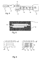
- Figure 4 shows segmentation and two directional joining of objects. New additional steps have been added compared to the single directional processing in Figure 3.
- a graph 41 of the image is constructed. The construction of the graph by finding field separators is described below.
- fields are detected in field detection step 42 by finding areas that are enclosed by edges of the graph. The relevant areas are classified as fields containing text blocks 47.
- the reading order 45 is determined in step 44. The reading direction detection is based upon the document spectrum. Using the fields of the text blocks 47, the contained connected components 43 and the reading order 45 as input, the Line Build step 46 joins the characters to lines as required along the direction found.
- a graph-representation of a document is created using the background of a scan. Pixels in the scan are classified as background (usually white) or foreground (usually black). Because only large areas of white provide information on fields, small noise objects are removed, e.g. by down-sampling the image. The down-sampled image may further be de-speckled to remove single foreground (black) pixels.
- the next task is to extract the important white areas.
- the first step is to detect so-called white runs, one pixel high areas of adjacent background pixels. White runs that are shorter than a predetermined minimal length are excluded from the processing.
- Figure 5 shows, as an example, four horizontal runs 51 of white pixels, that are adjacent in vertical direction.
- Foreground area 53 is assumed to have foreground pixels directly surrounding the white runs 51.
- a "maximal white rectangle" is defined as the largest rectangular area that can be constructed from the adjacent white runs 51, hence a rectangular white area that can not be extended without including black (foreground) pixels.
- a maximal white rectangle 52 is shown based on the four white runs 51 having a length as indicated by the vertical dotted lines and a width of 4 pixels. When a white rectangle can not be extended it has a so-called maximal separating power. Such a rectangle is not a smaller part of a more significant white area. Hence the rectangle 52 is the only possible maximal rectangle of width 4. Further rectangles can be constructed of width 3 or 2. A further example is shown in Figure 6.
- white rectangles are done separately in different separation directions, e.g. horizontal and vertical white rectangles.
- Vertical white rectangles are detected by rotating the image, and detecting horizontal white runs for the rotated image. It is noted that depending on the type of image or application also other separation directions may be selected such as diagonal.
- An algorithm for constructing maximal white rectangles is as follows.
- the input of the algorithm consists of all horizontal one pixel high white runs (WR) detected from a given image.
- Each white run is represented as a rectangle characterized by a set of coordinates ((x 1 ,y 1 ),(x 2 ,y 2 )), where and x 1 and y 1 are coordinates of its top left corner and x 2 ,y 2 are the coordinates of its bottom right corner.
- Each white run present in the active ordered object INPUT LIST is tested on an extension possibility.
- the extension possibility is formulated in the condition whether a given WR, labeled by p , can produce a maximal white rectangle (MWR) or not.
- extension possibility FALSE
- p is already a maximal one
- p is deleted from the active INPUT LIST and written to the active RESULT LIST.
- the extension possibility is TRUE, the test for extension is repeated until all MWRs initiated by p have been constructed. Then p is deleted from the INPUT LIST and all MWRs obtained from p are written to the active RESULT LIST. When all white rectangles from the INPUT LIST have been processed, the RESULT LIST will contain all MWRs.
- a sort on the y value is applied to the INPUT LIST. First, the algorithm is applied for horizontal WRs, i.e. for white runs with width larger than height. And after a 90° turn of the image it can be applied to vertical WRs.
- the algorithm for constructing the maximal rectangles is as follows.
- the rectangle data are stored as a linked list, with, at least, the coordinates of the rectangle vertices contained in it.
- the INPUT and RESULT LISTs are stored as a linked list too, with, at least, three elements, such as the number of white rectangles, and pointers on the first and the last element in the linked list.
- the following steps are executed: Activate INPUT LIST; Initiate RESULT LIST; Initiate BUFFER for temporary coordinates of the selected rectangle. Start from the first white rectangle, labeled by p 1 , out of the active ordered INPUT LIST. The next white rectangle on the list is labeled by p 2 .
- Figure 6 shows construction of maximal white rectangles.
- the pixel coordinates are displayed along a horizontal x axis and a vertical y axis.
- Four white runs 61 are shown left in the Figure.
- the white runs (WR) are described as rectangles with the coordinates of their upper and bottom corners correspondingly:
- the INPUT LIST contain the four white runs 61.
- the first element from the INPUT LIST is WR 1 ((10,1),(50,2)). Label WR 1 as p 1 .
- the first candidate for extension is WR 2 ((10,2),(50,3)).
- Test p 1 and p n1 on the absorption effect with p 1,n1 As follows from absorption test both p 1 and p n1 are absorbed by p 1,n1 .
- p (1,n1),t1 has no extension possibility. It means that p (1,n1),t1 is maximal.
- the second candidate WR 4 ((40,3),(60,4)) is found.
- the test fails, i.e. no absorption.
- Test p 1,n1 again on extension possibility. The test fails and p 1,n1 is maximal.
- the INPUT LIST on this stage contains two write runs, i.e. WR 3 : ((5,3),(30,4)), WR 4 : ((40,3),(60,4)). Start from WR 3 , and label it as p 2 . Repeat test on extension possibility for p 2 . The test fails, p 2 is maximal. Write p 2 with the coordinates ((5,3),(30,4)) to the RESULT LIST. Remove p 2 from the INPUT LIST. Proceed with WR 4 and label it as p 3 . Test on extension possibility for p 3 gives us that p 3 is maximal. Write p 3 with the coordinates ((40,3),(60,4)) to the RESULT LIST.
- the RESULT LIST contains five maximal white rectangles, i.e. MWR 1 : ((10,1),(50,3)) indicated in Figure 6 as 64, MWR 2 : ((10,1),(30,4)) indicated as 62, MWR 3 : ((40,1),(50,4)) indicated as 63, and MWR 4 : ((5,3),(30,4)) as 65, MWR 5 : ((40,3),(60,4)) as 66.
- MWR 1 ((10,1),(50,3)) indicated in Figure 6 as 64
- MWR 2 ((10,1),(30,4)) indicated as 62
- MWR 3 ((40,1),(50,4)) indicated as 63
- MWR 4 ((5,3),(30,4)) as 65
- MWR 5 ((40,3),(60,4)) as 66.
- Figure 7 shows a next step in the method according to the invention, namely a cleaning step of overlapping maximal white rectangles.
- a cleaning step of overlapping maximal white rectangles.
- plural overlapping maximal white rectangles are consolidated into a single so-called "Informative Maximal Rectangle" (IWR) that combines the most relevant properties of the original maximal white rectangles, as discussed below in detail.
- IWR Informative Maximal Rectangle
- the cleaning may further include steps like checking on size and spatial relation.
- the upper part of Figure 7 shows, as an example, two maximal white rectangles MWR1 and MWR2.
- the pair is consolidated into a single Informative White Rectangle IWR in the cleaning step as shown in the lower part of the Figure.
- the process of detecting overlap and consolidating is repeated until no relevant pairs can be formed anymore.
- a criterion for forming pairs may be the size of the overlap area.
- Further cleaning steps may include removing thin or short rectangles or rectangles that have an aspect ratio below a certain predefined value.
- the criteria for removing are based on the type of image, e.g. a width below a predefined number of pixels indicates a separator of text lines and is not relevant for separating fields, and a length below a certain value is not relevant in view of the expected sizes of the fields.
- An algorithm for the cleaning step is as follows.
- the start of the cleaning procedure is the whole set of MWRs constructed as described above with reference to Figures 5 and 6.
- the cleaning procedure is applied to discard non-informative MWRs. For this reason a measure of non-informativeness is defined. For example a long MWR is more informative than a short one. A low aspect ratio indicates a more or less square rectangle that is less informative. Further, extremely thin rectangles, which for instance separate two text lines, must be excluded.
- All MWRs are classified as being horizontal, vertical or square by computing the ration between their heights and widths. Square MWRs are deleted because of their non-informativeness.
- the cleaning technique is applied which consists of three steps:
- Figure 8 shows such a graph on a newspaper page.
- the picture shows a down-sampled digital image 80 of a newspaper page.
- the original text is visible in black in a down-sampled version corresponding to Figure 2.
- the informative rectangles IWR constituting separating elements are shown in gray.
- intersections of separating elements constituted by horizontal and vertical white IWRs are determined.
- the intersection point of two IWRs is indicated by a small black square representing a vertex or vertex 81 in the graph.
- Edges 82 that represent lines that separate the fields in the page are constructed by connecting pairs of vertices 81 via ''field separators".
- the edges 82 of the graph are shown in white.
- the distance between the two vertices of an edge i.e. the length, is assigned as weight to the edge for further processing.
- a different parameter is used for assigning the weight, e.g. the colour of the pixels.
- An algorithm for constructing the graph is as follows.
- Each rectangle r ⁇ is classified as horizontal, vertical or square based on the ratio of its height and width.
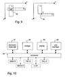
- Figure 9 shows two types of intersection of maximal rectangles.
- the intersection points of vertical and horizontal informative maximal rectangles are determined to find the position of vertices of the graph, i.e. to determine the exact coordinates of the vertices.
- the left part of the Figure shows a first type of intersection of vertical IWR v and a horizontal IWR h, which results in a rectangular area 88 with a center of intersection point P.
- the right part of the Figure shows a second type of intersection of a vertical IWR v and a horizontal IWR h, that results in a single intersection point 89 with a center of intersection at P'.
- the graph as constructed may now be further processed for classifying the areas within the graph as text blocks or a similar classification depending on the type of picture.
- the graph is augmented by including foreground separators, e.g. black lines or patterned lines such as dashed/dotted lines, in the analysis.
- edges of photos or graphic objects which are detected can be included in the analysis.
- the present segmenting method may also include a step of removing foreground separators. First, foreground separators are recognized and reconstructed as single objects. The components that constitute a patterned line are connected by analyzing element heuristics, spatial relation heuristics and line heuristics, i.e.
- a further method for reconstructing a solid line from a patterned line is down-sampling and/or using the Run Length Smoothing Algorithm (RLSA) as described by K.Y. Wong, R.G. Casey, F.M. Wahl in "Document analysis system” IBM J. Res. Dev 26 (1982) 647-656. After detecting the foreground separators they are replaced by background pixels. The effect is that larger maximal white rectangles can be constructed, or supporting any other suitable method using the background pixel property for finding background separators.
- RLSA Run Length Smoothing Algorithm
- Figure 11 shows a flow diagram of a method, according to the invention, for defining fields in an image of pixels, based on generating a list of shortest cycles in a graph representation of the image.
- the method first constructs a mathematical description of the image of pixels in the form of a graph having vertices and edges connecting the vertices. Then, the graph is broken up into contiguous areas having a smallest possible perimeter, i.e. areas that are delineated by smallest possible cycles formed by edges of the graph. Finally, fields are defined in the pixel domain of the original image, in correspondance with the (mathematically defined) smallest cycles. This approach of searching for smallest possible cycles in the graph has the advantage, that the corresponding calculations are simple and fast.
- a graph is constructed having edges that correspond to background areas separating the fields in the image.
- the vertices in the graph correspond to angular points of the fields in the image.
- the fields in the image are for example text blocks in a newspaper page. Basically, the fields are polygon areas having mainly vertical and horizontal borders, but they are not necessarily rectangular. For instance, L-shaped text blocks appear frequently in practical situations.
- a weight is assigned to each edge.
- the weight of an edge in a graph of a layout type image to be segmented may be the Euclidian distance between the vertices, i.e. its length in the original image.
- a suitable measure for weight may be traveling time, or a different parameter like cost.
- the weight for each edge is calculated and added to the graph data-structure.
- a shortest cycle is defined as a closed path in the graph via edges that are connected by vertices, which path has the lowest sum of weights accumulated by adding the weights of the edges involved.
- a list of shortest cycles is created having an initially empty content, and a first starting point, a vertex or edge, within the graph is determined. For example for this purpose the graph is sorted and the first starting point is set to be the upper left corner vertex of the graph.
- the process now enters a loop of steps S4, S5, S6 and S7, in which a shortest cycle is constructed starting from the preselected starting point.
- step S7 selects a new starting point for finding a next shortest cycle. The status of the vertices or edges in the graph for still being available as candidate starting point is maintained. If no candidate starting points are remaining, step S7 terminates the loop and proceeds to the next step S8.
- the CYCLE step S4 determines a shortest cycle for the selected starting point.
- the shortest cycle algorithm may construct every possible cycle and select the shortest cycle from the set.
- the shortest cycle found is judged in NEW step S5 for being new with respect to the list of shortest cycles already found. If the shortest cycle is new, the ADD step S6 is performed for adding the latest shortest cycle to the list of shortest cycles. Suitable algorithms for constructing the shortest cycle, selecting and maintaining starting points and constructing the list of new shortest cycles are described below.
- the list contains the shortest cycles that can be formed in the graph.
- the NEXT step S7 may also be arranged for detecting if a required specific part of the graph has been fully processed. Such a required part can be defined if it is known from the application that only fields contained in a specific part of the graph need to be constructed. The list of shortest cycles will then contain the shortest cycles in that part of the graph only.
- a FIELD step S8 the fields are defined on the basis of the list of shortest cycles.
- a field is a polygon represented by the vertices and edges in the shortest cycle that encloses the field.
- the step S8 may also include additional steps for detecting shortest cycles that contain other, smaller shortest cycles, and for correcting the initial results for that case.
- the FIELD step S8 includes an additional step for defining the fields. First it is determined if a shortest cycle that encloses a larger area further contains a smaller area that itself is enclosed by a second shortest cycle. The corresponding larger field is corrected by subtracting the smaller enclosed area from the larger enclosed area. Alternatively the field corresponding to the second shortest cycle is processed before processing the field corresponding to the first shortest cycle. When processing the latter the first area is skipped.
- the additional step is further explained below with reference to Figure 12b.
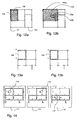
- Figures 12a and 12b show graphs and cycles in the graphs.
- the graph is constituted by edges 100 and vertices 101. Each area enclosed by edges 100 corresponds to a field in the original image as represented by the graph.
- Figure 12a shows a shortest cycle 102 around a text area 105.
- Figure 12b shows a further graph that has a further text area 104 enclosed by a rectangular shortest cycle 104a. The area 104 encloses a further, smaller text area 103a and a second smaller area 103b. The smaller areas are also enclosed by shortest cycles. This situation may be handled in one of two alternative approaches.
- the areas are sorted on size of their enclosed area before determining further properties of the fields like reading direction.
- the reading order in the smaller text block is determined first.
- the area of the smaller cycle is skipped, such that characters in that area do not influence the determination of reading direction in the larger area.
- the FIELD step S8 comprises detecting such inclusion and compensating for it.
- a first sub-step it is determined if a larger shortest cycle includes a smaller shortest cycle. Comparing the enclosed areas and/or the location of the shortest cycles reveals the enclosure. For this purpose shared edges or vertices may be used.
- a second sub-step the enclosed area of the smaller shortest cycle is subtracted from the enclosed area of the larger shortest cycle.
- Shortest cycles can be detected in several ways, for example using the following algorithm.
- Figures 13a and 13b show shortest cycle detection.
- a method is shown for finding a shortest cycle based on selecting a starting edge 108.
- a graph is shown that is temporarily reduced by removing starting edge 108 between the vertices u and v.
- a shortest path in the graph is constructed from vertex u to vertex v.
- Figure 13b shows constructing the shortest cycle by resetting the edge 109.
- Suitable algorithms for constructing the shortest path between two vertices in a graph can be found in "Graph theory: an algorithmic approach" by N. Christofides, Academic Press, New York, 1975, in particular Dijkstra's algorithm described therein.
- a list of shortest cycles is constructed covering the total of the graph.
- the constructing of the list of shortest cycles comprises only including a shortest cycle on the list if that cycle is not already included in the list.
- the amount of calculations can be drastically limited when a so-called graph reduction method is applied.
- a shortest cycle that is detected is removed from the graph, and detecting shortest cycles is continued within the reduced graph, preferably next to the removed cycle. In this way, the graph is successively reduced until nothing remains of it.
- each edge is assigned a potential number indicating the maximal number of shortest cycles it can be part of, normally 1 for an edge situated at an outer border of the graph and 2 for an edge situated within the graph borders.
- a shortest cycle 115 is shown detected in the upper left area. Once detected, the number of potential cycles of the 4 edges included in this shortest cycle is reduced by 1.
- the second step 112 the upper left edges that have a potential number of 0, are removed from the graph.
- a second shortest cycle 116 is detected in the second area to the right, adjacent to the area of cycle 115.
- the potential numbers are reduced and two more sides are removed from the graph.
- a third shortest cycle 117 is detected on the second row left.
- the determining of the shortest cycle is performed by constructing a minimal spanning tree.
- a minimal spanning tree represents all shortest paths from a root vertex to the other vertices.
- the root vertex u is the first vertex of the removed edge.
- the tree is used to find the shortest path to the other vertex v of the removed edge.
- a data structure of pointers is used to represent the minimal spanning tree.
- the tree is constructed by adding a vertex per iteration, which vertex has the shortest distance to the root vertex of all vertices not yet in the tree.
- the respective new vertex is found by checking the neighbors of all vertices that are already included in the tree and calculating the distance to the root if that neighbor is not yet in the tree. As soon as the vertex v is added to the tree the process is stopped.
- a separate list with the neighbors of the current iteration can be maintained
- the minimal spanning tree may also be represented in variables of the data structure that represents the graph, in particular associated with the vertex elements of the graph.
- Each vertex element has additional variables to store the tree.
- the variables For finding a new shortest cycle the variables must be initialized.
- the variables are not individually initialized, but an additional variable is added to each vertex that is initialized before the first tree is constructed. For each subsequent tree a different value is stored in the additional variable, identifying the respective vertex as being part of the current tree. Constructing the tree using variables in the graph is advantageous in that no separate data structure needs to be maintained for the minimal spanning tree.
- Figure 10 shows a device for segmenting a picture using a method according to the invention.
- the device has an input unit 91 for entering a digital image.
- the input unit may comprise a scanning unit for scanning an image from paper such as an electro-optical scanner, or a digital communication unit for receiving the image from a network like internet, or a playback unit for retrieving digital information from a record carrier like an optical disc drive.
- the input unit 91 is coupled to a processing unit 94, which cooperates with a memory unit 92.
- the processing unit 94 may comprise a general purpose computer central processing unit (CPU) and supporting circuits and operates using software for performing the segmentation as described above.
- CPU general purpose computer central processing unit
- the processing unit may also include a user interface 95 provided with control means such as a keyboard, a mouse device or operator buttons.
- the output of the processing unit is coupled to a display unit 93.
- the display unit is a printing unit for outputting a processed image on paper, or a recording unit for storing the segmented image on a record carrier like a magnetic tape or optical disk.
- the invention has been mainly explained by embodiments using a Japanese newspaper page as the digital image to be segmented
- the invention is also suitable for any digital representation of any text or image having a layout in fields on a background, such as electrical circuits in layout images for IC design or streets and buildings on city maps. Also for a very different application such as detecting closed sub-circuits in electric chains this approach may be used.
- the graph as starting point for executing the segmenting by shortest cycles may be constructed differently than the graph described above based on the MWR system. For example a graph may be constructed using tiles as described in the article by Antonacopoulos mentioned above, although the particular graph disclosed in Antonacopoulos is different from that of the present invention and cannot be used.
- the weight assigned to an edge in the graph is not necessarily the distance. It must be selected to correspond to a contribution to the shortest cycle, for example the weight may be the surface of the tile. It is noted, that in this document the use of the verb 'comprise' and its conjugations does not exclude the presence of other elements or steps than those listed and the word 'a' or 'an' preceding an element does not exclude the presence of a plurality of such elements, that any reference signs do not limit the scope of the claims, that the invention and every unit or means mentioned may be implemented by suitable hardware and/or software and that several 'means' or 'units' may be represented by the same item. Further, the scope of the invention is not limited to the embodiments, and the invention lies in each and every novel feature or combination of features described above.
Landscapes
- Engineering & Computer Science (AREA)
- Computer Vision & Pattern Recognition (AREA)
- Artificial Intelligence (AREA)
- Physics & Mathematics (AREA)
- General Physics & Mathematics (AREA)
- Multimedia (AREA)
- Theoretical Computer Science (AREA)
- Character Input (AREA)
Priority Applications (1)
| Application Number | Priority Date | Filing Date | Title |
|---|---|---|---|
| EP03078519A EP1439484B1 (de) | 2002-11-22 | 2003-11-10 | Segmentierung eines Bildes mittels kürzester Zyklen |
Applications Claiming Priority (3)
| Application Number | Priority Date | Filing Date | Title |
|---|---|---|---|
| EP02079935 | 2002-11-22 | ||
| EP02079935 | 2002-11-22 | ||
| EP03078519A EP1439484B1 (de) | 2002-11-22 | 2003-11-10 | Segmentierung eines Bildes mittels kürzester Zyklen |
Publications (2)
| Publication Number | Publication Date |
|---|---|
| EP1439484A1 true EP1439484A1 (de) | 2004-07-21 |
| EP1439484B1 EP1439484B1 (de) | 2009-01-21 |
Family
ID=32598789
Family Applications (1)
| Application Number | Title | Priority Date | Filing Date |
|---|---|---|---|
| EP03078519A Expired - Lifetime EP1439484B1 (de) | 2002-11-22 | 2003-11-10 | Segmentierung eines Bildes mittels kürzester Zyklen |
Country Status (1)
| Country | Link |
|---|---|
| EP (1) | EP1439484B1 (de) |
Citations (3)
| Publication number | Priority date | Publication date | Assignee | Title |
|---|---|---|---|---|
| EP0472313A2 (de) * | 1990-08-03 | 1992-02-26 | Canon Kabushiki Kaisha | Gerät und Verfahren zur Bildverarbeitung |
| US20010026633A1 (en) * | 1998-12-11 | 2001-10-04 | Philips Electronics North America Corporation | Method for detecting a face in a digital image |
| US6470095B2 (en) * | 1998-10-13 | 2002-10-22 | Xerox Corporation | Automatic extraction of text regions and region borders for an electronic work surface |
-
2003
- 2003-11-10 EP EP03078519A patent/EP1439484B1/de not_active Expired - Lifetime
Patent Citations (3)
| Publication number | Priority date | Publication date | Assignee | Title |
|---|---|---|---|---|
| EP0472313A2 (de) * | 1990-08-03 | 1992-02-26 | Canon Kabushiki Kaisha | Gerät und Verfahren zur Bildverarbeitung |
| US6470095B2 (en) * | 1998-10-13 | 2002-10-22 | Xerox Corporation | Automatic extraction of text regions and region borders for an electronic work surface |
| US20010026633A1 (en) * | 1998-12-11 | 2001-10-04 | Philips Electronics North America Corporation | Method for detecting a face in a digital image |
Non-Patent Citations (2)
| Title |
|---|
| ANTONACOPOULOS A ET AL: "Flexible page segmentation using the background", PATTERN RECOGNITION, 1994. VOL. 2 - CONFERENCE B: COMPUTER VISION & IMAGE PROCESSING., PROCEEDINGS OF THE 12TH IAPR INTERNATIONAL. CONFERENCE ON JERUSALEM, ISRAEL 9-13 OCT. 1994, LOS ALAMITOS, CA, USA,IEEE COMPUT. SOC, 9 October 1994 (1994-10-09), pages 339 - 344, XP010216306, ISBN: 0-8186-6270-0 * |
| BELAID Y ET AL: "Item searching in forms: Application to French tax form", DOCUMENT ANALYSIS AND RECOGNITION, 1995., PROCEEDINGS OF THE THIRD INTERNATIONAL CONFERENCE ON MONTREAL, QUE., CANADA 14-16 AUG. 1995, LOS ALAMITOS, CA, USA,IEEE COMPUT. SOC, US, 14 August 1995 (1995-08-14), pages 744 - 747, XP010231002, ISBN: 0-8186-7128-9 * |
Also Published As
| Publication number | Publication date |
|---|---|
| EP1439484B1 (de) | 2009-01-21 |
Similar Documents
| Publication | Publication Date | Title |
|---|---|---|
| JP5854802B2 (ja) | 画像処理装置、画像処理方法、及びコンピュータプログラム | |
| JP3950777B2 (ja) | 画像処理方法、画像処理装置および画像処理プログラム | |
| US20090148039A1 (en) | Colour document layout analysis with multi-level decomposition | |
| US7529407B2 (en) | Segmenting an image via shortest cycles | |
| CN101206719A (zh) | 用于检测和处理图像中特定图案的方法和设备 | |
| JP2001109895A (ja) | 複数のディジタル画像の処理方法 | |
| JPH05217019A (ja) | ビジネスフォーム識別システム及び画像処理システム | |
| JP4535584B2 (ja) | ディジタル画像処理方法 | |
| CN109948533B (zh) | 一种文本检测方法、装置、设备及可读存储介质 | |
| US7570811B2 (en) | Segmenting an image via a graph | |
| CN115861609A (zh) | 遥感图像的分割标注方法、电子设备及存储介质 | |
| US7336825B2 (en) | Segmenting a composite image via minimum areas | |
| JP2004282701A5 (de) | ||
| EP1439484B1 (de) | Segmentierung eines Bildes mittels kürzester Zyklen | |
| Ablameyko et al. | Computer-aided cartographical system for map digitizing | |
| EP1439485B1 (de) | Segmentierung eines zusammengesetzten Bildes mittels Basis-Rechtecken | |
| EP1229497B1 (de) | Lauflängenbasierte verbundene Komponenten und Konturverfolgung zur Laufzeitverbesserung eines Extraktionsalgorithmus für kreisförmigen Bereich | |
| JP2845107B2 (ja) | 画像処理装置 | |
| Kumar et al. | A hybrid approach for complex layout detection of newspapers in Gurumukhi script using deep learning | |
| JP4409678B2 (ja) | 罫線抽出方式 | |
| JP2005302056A (ja) | パターン抽出装置 | |
| Ablameyko et al. | Interpretation of colour maps. A combination of automatic and interactive techniques | |
| Marchand-Maillet et al. | A minimum spanning tree approach to line image analysis | |
| JP3435193B2 (ja) | 文字列の切り出し方法 | |
| JP3534997B2 (ja) | 罫線抽出装置および方法 |
Legal Events
| Date | Code | Title | Description |
|---|---|---|---|
| PUAI | Public reference made under article 153(3) epc to a published international application that has entered the european phase |
Free format text: ORIGINAL CODE: 0009012 |
|
| AK | Designated contracting states |
Kind code of ref document: A1 Designated state(s): AT BE BG CH CY CZ DE DK EE ES FI FR GB GR HU IE IT LI LU MC NL PT RO SE SI SK TR |
|
| AX | Request for extension of the european patent |
Extension state: AL LT LV MK |
|
| 17P | Request for examination filed |
Effective date: 20050121 |
|
| AKX | Designation fees paid |
Designated state(s): AT BE BG CH CY CZ DE DK EE ES FI FR GB GR HU IE IT LI LU MC NL PT RO SE SI SK TR |
|
| 17Q | First examination report despatched |
Effective date: 20070504 |
|
| GRAP | Despatch of communication of intention to grant a patent |
Free format text: ORIGINAL CODE: EPIDOSNIGR1 |
|
| GRAS | Grant fee paid |
Free format text: ORIGINAL CODE: EPIDOSNIGR3 |
|
| RIN1 | Information on inventor provided before grant (corrected) |
Inventor name: MARQUERING, HENRICUS A. Inventor name: PEETEN, DENNIS |
|
| GRAA | (expected) grant |
Free format text: ORIGINAL CODE: 0009210 |
|
| AK | Designated contracting states |
Kind code of ref document: B1 Designated state(s): AT BE BG CH CY CZ DE DK EE ES FI FR GB GR HU IE IT LI LU MC NL PT RO SE SI SK TR |
|
| REG | Reference to a national code |
Ref country code: GB Ref legal event code: FG4D |
|
| REG | Reference to a national code |
Ref country code: CH Ref legal event code: EP |
|
| REG | Reference to a national code |
Ref country code: IE Ref legal event code: FG4D |
|
| REF | Corresponds to: |
Ref document number: 60325934 Country of ref document: DE Date of ref document: 20090312 Kind code of ref document: P |
|
| PG25 | Lapsed in a contracting state [announced via postgrant information from national office to epo] |
Ref country code: SI Free format text: LAPSE BECAUSE OF FAILURE TO SUBMIT A TRANSLATION OF THE DESCRIPTION OR TO PAY THE FEE WITHIN THE PRESCRIBED TIME-LIMIT Effective date: 20090121 Ref country code: ES Free format text: LAPSE BECAUSE OF FAILURE TO SUBMIT A TRANSLATION OF THE DESCRIPTION OR TO PAY THE FEE WITHIN THE PRESCRIBED TIME-LIMIT Effective date: 20090502 Ref country code: FI Free format text: LAPSE BECAUSE OF FAILURE TO SUBMIT A TRANSLATION OF THE DESCRIPTION OR TO PAY THE FEE WITHIN THE PRESCRIBED TIME-LIMIT Effective date: 20090121 |
|
| PG25 | Lapsed in a contracting state [announced via postgrant information from national office to epo] |
Ref country code: PT Free format text: LAPSE BECAUSE OF FAILURE TO SUBMIT A TRANSLATION OF THE DESCRIPTION OR TO PAY THE FEE WITHIN THE PRESCRIBED TIME-LIMIT Effective date: 20090622 Ref country code: SE Free format text: LAPSE BECAUSE OF FAILURE TO SUBMIT A TRANSLATION OF THE DESCRIPTION OR TO PAY THE FEE WITHIN THE PRESCRIBED TIME-LIMIT Effective date: 20090421 Ref country code: AT Free format text: LAPSE BECAUSE OF FAILURE TO SUBMIT A TRANSLATION OF THE DESCRIPTION OR TO PAY THE FEE WITHIN THE PRESCRIBED TIME-LIMIT Effective date: 20090121 |
|
| PG25 | Lapsed in a contracting state [announced via postgrant information from national office to epo] |
Ref country code: BE Free format text: LAPSE BECAUSE OF FAILURE TO SUBMIT A TRANSLATION OF THE DESCRIPTION OR TO PAY THE FEE WITHIN THE PRESCRIBED TIME-LIMIT Effective date: 20090121 |
|
| PG25 | Lapsed in a contracting state [announced via postgrant information from national office to epo] |
Ref country code: DK Free format text: LAPSE BECAUSE OF FAILURE TO SUBMIT A TRANSLATION OF THE DESCRIPTION OR TO PAY THE FEE WITHIN THE PRESCRIBED TIME-LIMIT Effective date: 20090121 Ref country code: EE Free format text: LAPSE BECAUSE OF FAILURE TO SUBMIT A TRANSLATION OF THE DESCRIPTION OR TO PAY THE FEE WITHIN THE PRESCRIBED TIME-LIMIT Effective date: 20090121 Ref country code: CZ Free format text: LAPSE BECAUSE OF FAILURE TO SUBMIT A TRANSLATION OF THE DESCRIPTION OR TO PAY THE FEE WITHIN THE PRESCRIBED TIME-LIMIT Effective date: 20090121 |
|
| PLBE | No opposition filed within time limit |
Free format text: ORIGINAL CODE: 0009261 |
|
| STAA | Information on the status of an ep patent application or granted ep patent |
Free format text: STATUS: NO OPPOSITION FILED WITHIN TIME LIMIT |
|
| PG25 | Lapsed in a contracting state [announced via postgrant information from national office to epo] |
Ref country code: RO Free format text: LAPSE BECAUSE OF FAILURE TO SUBMIT A TRANSLATION OF THE DESCRIPTION OR TO PAY THE FEE WITHIN THE PRESCRIBED TIME-LIMIT Effective date: 20090121 Ref country code: SK Free format text: LAPSE BECAUSE OF FAILURE TO SUBMIT A TRANSLATION OF THE DESCRIPTION OR TO PAY THE FEE WITHIN THE PRESCRIBED TIME-LIMIT Effective date: 20090121 |
|
| 26N | No opposition filed |
Effective date: 20091022 |
|
| PG25 | Lapsed in a contracting state [announced via postgrant information from national office to epo] |
Ref country code: BG Free format text: LAPSE BECAUSE OF FAILURE TO SUBMIT A TRANSLATION OF THE DESCRIPTION OR TO PAY THE FEE WITHIN THE PRESCRIBED TIME-LIMIT Effective date: 20090421 |
|
| REG | Reference to a national code |
Ref country code: NL Ref legal event code: V1 Effective date: 20100601 |
|
| PG25 | Lapsed in a contracting state [announced via postgrant information from national office to epo] |
Ref country code: MC Free format text: LAPSE BECAUSE OF NON-PAYMENT OF DUE FEES Effective date: 20091130 |
|
| REG | Reference to a national code |
Ref country code: CH Ref legal event code: PL |
|
| GBPC | Gb: european patent ceased through non-payment of renewal fee |
Effective date: 20091110 |
|
| REG | Reference to a national code |
Ref country code: FR Ref legal event code: ST Effective date: 20100730 |
|
| PG25 | Lapsed in a contracting state [announced via postgrant information from national office to epo] |
Ref country code: LI Free format text: LAPSE BECAUSE OF NON-PAYMENT OF DUE FEES Effective date: 20091130 Ref country code: NL Free format text: LAPSE BECAUSE OF NON-PAYMENT OF DUE FEES Effective date: 20100601 Ref country code: IE Free format text: LAPSE BECAUSE OF NON-PAYMENT OF DUE FEES Effective date: 20091110 Ref country code: GR Free format text: LAPSE BECAUSE OF FAILURE TO SUBMIT A TRANSLATION OF THE DESCRIPTION OR TO PAY THE FEE WITHIN THE PRESCRIBED TIME-LIMIT Effective date: 20090422 Ref country code: CH Free format text: LAPSE BECAUSE OF NON-PAYMENT OF DUE FEES Effective date: 20091130 Ref country code: FR Free format text: LAPSE BECAUSE OF NON-PAYMENT OF DUE FEES Effective date: 20091130 |
|
| PG25 | Lapsed in a contracting state [announced via postgrant information from national office to epo] |
Ref country code: DE Free format text: LAPSE BECAUSE OF NON-PAYMENT OF DUE FEES Effective date: 20100601 |
|
| PG25 | Lapsed in a contracting state [announced via postgrant information from national office to epo] |
Ref country code: GB Free format text: LAPSE BECAUSE OF NON-PAYMENT OF DUE FEES Effective date: 20091110 |
|
| PG25 | Lapsed in a contracting state [announced via postgrant information from national office to epo] |
Ref country code: IT Free format text: LAPSE BECAUSE OF FAILURE TO SUBMIT A TRANSLATION OF THE DESCRIPTION OR TO PAY THE FEE WITHIN THE PRESCRIBED TIME-LIMIT Effective date: 20090121 |
|
| PG25 | Lapsed in a contracting state [announced via postgrant information from national office to epo] |
Ref country code: LU Free format text: LAPSE BECAUSE OF NON-PAYMENT OF DUE FEES Effective date: 20091110 |
|
| PG25 | Lapsed in a contracting state [announced via postgrant information from national office to epo] |
Ref country code: HU Free format text: LAPSE BECAUSE OF FAILURE TO SUBMIT A TRANSLATION OF THE DESCRIPTION OR TO PAY THE FEE WITHIN THE PRESCRIBED TIME-LIMIT Effective date: 20090722 |
|
| PG25 | Lapsed in a contracting state [announced via postgrant information from national office to epo] |
Ref country code: TR Free format text: LAPSE BECAUSE OF FAILURE TO SUBMIT A TRANSLATION OF THE DESCRIPTION OR TO PAY THE FEE WITHIN THE PRESCRIBED TIME-LIMIT Effective date: 20090121 |
|
| PG25 | Lapsed in a contracting state [announced via postgrant information from national office to epo] |
Ref country code: CY Free format text: LAPSE BECAUSE OF FAILURE TO SUBMIT A TRANSLATION OF THE DESCRIPTION OR TO PAY THE FEE WITHIN THE PRESCRIBED TIME-LIMIT Effective date: 20090121 |