EP1439439A2 - Multi-axis cutter diameter compensation for numeric control machine tools - Google Patents
Multi-axis cutter diameter compensation for numeric control machine tools Download PDFInfo
- Publication number
- EP1439439A2 EP1439439A2 EP04075098A EP04075098A EP1439439A2 EP 1439439 A2 EP1439439 A2 EP 1439439A2 EP 04075098 A EP04075098 A EP 04075098A EP 04075098 A EP04075098 A EP 04075098A EP 1439439 A2 EP1439439 A2 EP 1439439A2
- Authority
- EP
- European Patent Office
- Prior art keywords
- cutter
- software component
- tool
- addressable
- radius
- Prior art date
- Legal status (The legal status is an assumption and is not a legal conclusion. Google has not performed a legal analysis and makes no representation as to the accuracy of the status listed.)
- Granted
Links
Images




Classifications
-
- G—PHYSICS
- G05—CONTROLLING; REGULATING
- G05B—CONTROL OR REGULATING SYSTEMS IN GENERAL; FUNCTIONAL ELEMENTS OF SUCH SYSTEMS; MONITORING OR TESTING ARRANGEMENTS FOR SUCH SYSTEMS OR ELEMENTS
- G05B19/00—Program-control systems
- G05B19/02—Program-control systems electric
- G05B19/18—Numerical control [NC], i.e. automatically operating machines, in particular machine tools, e.g. in a manufacturing environment, so as to execute positioning, movement or co-ordinated operations by means of program data in numerical form
- G05B19/4097—Numerical control [NC], i.e. automatically operating machines, in particular machine tools, e.g. in a manufacturing environment, so as to execute positioning, movement or co-ordinated operations by means of program data in numerical form characterised by using design data to control NC machines, e.g. CAD/CAM
-
- G—PHYSICS
- G05—CONTROLLING; REGULATING
- G05B—CONTROL OR REGULATING SYSTEMS IN GENERAL; FUNCTIONAL ELEMENTS OF SUCH SYSTEMS; MONITORING OR TESTING ARRANGEMENTS FOR SUCH SYSTEMS OR ELEMENTS
- G05B2219/00—Program-control systems
- G05B2219/30—Nc systems
- G05B2219/35—Nc in input of data, input till input file format
- G05B2219/35165—Automatic cutter selection
-
- G—PHYSICS
- G05—CONTROLLING; REGULATING
- G05B—CONTROL OR REGULATING SYSTEMS IN GENERAL; FUNCTIONAL ELEMENTS OF SUCH SYSTEMS; MONITORING OR TESTING ARRANGEMENTS FOR SUCH SYSTEMS OR ELEMENTS
- G05B2219/00—Program-control systems
- G05B2219/30—Nc systems
- G05B2219/35—Nc in input of data, input till input file format
- G05B2219/35185—Select optimum tool radius
Definitions
- This invention relates generally to robotics and, more specifically, to numeric controlled machinery.
- the automated use of precision machining techniques is based upon precise movement of a motorized spindle through three-dimension space with a cutter chucked in the spindle.
- the cutter removes material based on its geometric relation to the spindle.
- a cutter with a known diameter is moved in precise, calculated strokes across the surface of the material being machined in order to produce a part.
- the cutter removes material based on its geometric relation to the spindle.
- a cutter is a tool that has a radius which represents the offset between the axis of the cutter and the cutter's cutting edge.
- the cutter also has a length that indicates the distance between one end of the cutting edge and the other. The cutter sits within a chuck on the turning spindle and when spinning, the length and radius of the cutter determine the location and the amount of material that the cutter will remove.
- Cutters can be readily and effectively sharpened, but doing so shortens the radius of the sharpened cutter in comparison to its radius when new.
- the sharpened cutter produces a part that is outside of tolerances. Rather than to produce parts that are out of tolerance, the cutters were not generally resharpened for use though nothing inherently prevented resharpening of the cutters.
- the present invention provides a method and software for facilitating the derivation of numeric controlled cutting programs (on-the-fly). By placing the derivation of the numeric control program at the production level, the manufacturer efficiently uses its inventory of cutters regardless of the current diameter of the cutter in use.
- a method for using previously sharpened cutters in an automated tool to produce a part is provided.
- a part for production on an automated tool is selected.
- a previously sharpened cutter is selected based upon its radius and gauge length, and the part is associated with the previously sharpened cutter.
- a numeric controlled cutting program is opened based upon the part and the radius and gauge length of the associated previously-sharpened cutter.
- a method for utilizing previously-sharpened cutters in an automated tool to produce a part is provided.
- a part for production on an automated tool is selected.
- a previously-sharpened cutter is selected based upon its radius and gauge length, and the part is associated with the previously sharpened cutter.
- a numeric controlled and cutting program is generated based upon the part and the radius and gauge length of the associated previously-sharpened cutter.
- the invention may also be practiced in distributed computing environments where tasks are performed by remote processing devices that are linked through a communications network.
- the program modules may be located in both local and remote memory storage devices. Execution of the program modules may occur locally in a stand-alone manner or remotely in a client/server manner. Examples of such distributed computing environments include local area networks of an office, enterprise wide computer networks, and the Internet.
- FIGURE 1 illustrates a typical client/server environment 10 in which an exemplary embodiment of the present invention operates.
- a computer system or client 1 such as the conventional personal computer or any devices operable to communicate over a network is connected to an Internet server computer 3 ("server").
- the server 3 is generally provided by an Internet service provider (ISP), which provides Internet access for a typical Internet user.
- ISP Internet service provider
- the server 3 is connected to a distributed computer network, such as the Internet or a wide area network (“WAN”), and enables the client 1 to communicate via the distributed computer network 5.
- WAN wide area network
- the client 1 communicates via combination of the server 3 and the distributed computer network 5 to a server 7, such as communication or an email server.
- servers 3 and 7 support email services, contain a message store for holding messages until delivery, and contain a translation facility or gateway for allowing users having different email programs to exchange mail.
- the server 7 is connected to an internal network 9, such as a local area network ("LAN") and enables the client 1 to communicate with the clients 11a, 11b, and 11c via the internal network 9.
- LAN local area network
- the clients 11a, 11b, and 11c are not only able to respond to a communication from the client 1, but are also able to initiate communication with the client 1.
- the clients 11a, 11b, and 11c can send information via the internal network 9 to the server 7.
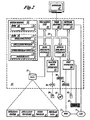
- an exemplary system for implementing the invention includes a conventional personal computer 11 which serves as a client.
- the client 11 may represent any or all of the clients 1, 11a, 11b, and 11c illustrated in FIGURE 1.
- the client 11 includes a processing unit 21, a system memory 22, and a system bus 23 that couples the system memory to the processing unit 21.
- the system memory 22 includes read-only memory (ROM) 24 and random access memory (RAM) 25.
- ROM read-only memory
- RAM random access memory
- a basic input/output system 26 (BIOS), containing basic routines that help to transfer information between elements with the client 11 such as during startup is stored in ROM 24.
- the client 11 further includes a hard disk drive 27, a magnetic disk drive 28, e.g.
- the hard disk drive 27, the magnetic disk drive 28, and an optical disk drive 30 are connected to the system bus 23 by a hard disk drive interface 32, a magnetic disk drive interface 33, and an optical disk drive interface 34, respectively.
- the drives and their associated computer-readable media provide non-volatile storage for the client 11.
- computer-readable media refers to a hard disk, a removable magnetic disk, and a CD-ROM disk
- other types of media which are readable by a computer such as magnetic cassettes, flash memory cards, digital video disks, Bernoulli cartridges, and the like, may also be used in the exemplary operating environment.
- a number of program modules may be stored in the drives and RAM 25, including an operating system 35, one or more application programs, such as an email program module 36, other program modules, such as the message manager program module 37, a local message store 38, and a database 39 for supporting email applications.
- a user may enter commands and information into the client 11 through a keyboard 40 and a pointing device, such as a mouse 42.
- Other input devices may include a pen, a touch operated device, a microphone, a joystick, a game pad, a satellite dish, a scanner, or the like.
- a port interface 46 that is coupled to the system bus, but may be connected by other interfaces, such as a serial port, a game port, or a universal serial bus (USB).
- a monitor 47 or other type of display device is also connected to the system bus 23 via an interface, such as the Video Doctor 48.
- personal computers typically include other peripheral output devices (not shown), such as speakers or printers.
- the client 11 operates typically in a networked environment using logical connections to one or more remote computers, such as the remote computer 49.
- the remote computer 49 may be an email server (which includes one or more message stores), as described above in connection with FIGURE 1.
- a file server (which includes one or more files stores), a router, a peer device or other common network note, and typically includes many or all of the elements described relative to the client 11.
- the logical connections depicted in FIGURE 2 include the local area network (LAN) or the wide area network (WAN) 5.
- LAN local area network
- WAN wide area network
- Such networking environments are commonplace in offices, enterprise wide computer networks, intranets, and the Internet.
- the client 11 When used in a LAN networking environment, the client 11 is connected to the LAN 9 through a network interface 53 or additionally through the WAN 5.
- the client 11 When used in an a WAN networking environment, the client 11 typically includes a modem 54 or other means for establishing communications over the WAN 5 such as the Internet.
- the modem 54 which may be internal or external is connected to the system bus 23 via the serial port interface 46.
- the program modules depicted relative to the client 11, or portions thereof may be stored in the remote memory storage device. It will be appreciated that the network connections shown are exemplary in other means of establishing a communications link between the computers may be used.
- the invention allows any of several clients 1, 11a, 11b, or 11c connected to the LAN 5 either directly or through the WAN 9 to initiate an exemplary routine 50.
- a user selects an NC control file defining the part the user seeks to produce.
- an NC control file is only but one means of defining the dimensions and shape of a machined part. Any suitable numeric model will suffice. Such models might include CAD/CAM models, finite element models and the like.
- the user selects a cutter for definition to associate with the model selected at the block 51. Taken together, the selected part model and the selected cutter will define an appropriate series of cutting strokes to machine a tool.
- the user checks the cutting diameter and comer radius against the range of undersized tools allowable for machining the part in question. In the event that the undersized tool is too large to cut the necessary comers in the machining of the tool, the tool is disqualified at a decision block 57.
- the display indicates that tool is out-of-range, the routine 50 returns to the block 53 where the operator can select another suitable cutter.
- the cutter gauge length is checked against the range of allowable gauge lengths.
- a determination is made whether the gauge length is allowed. If the gauge length is not allowed, at a block 65, an out-of-range warning is displayed on the display.
- the user is provided an opportunity to modify the gauge length.
- any of a number of commercial off-the-shelf products appropriate to compile an NC cutting program is invoked and the NC cutting program is compiled for producing the part in question with the selected cutter.
- the newly compiled NC program is run with the selected cutter to produce the part. According to the present invention, such parts will continue to be produced until the cutter is either too dull to reliably produce the defined part or a sufficient quantity of parts has been produced.
- a dialog box 75 allows the user to select the predefined definition of the part the operator wishes to produce.
- a list pane 77 with a scroll-down bar 79 allows the operator to survey those part definitions stored on the network. Where the user finds the appropriate part, the user moves a cursor to indicate that part and then either double-clicks on the definition or moves the cursor down to button 81 to click OK, thereby selecting the appropriate part definition. If for any reason the user wishes to defer the decision, the user merely clicks a button 83 and exits the process.
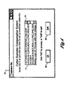
- a dialog box 85 provides means for selecting a cutter for creating the part 53 (FIGURE 4).
- the dialog box 85 displays in "grayed out” text, the name of the part the operator wishes to produce in a window pane 91 (indicating that the part definition is no longer selectable).
- a second pane 93 allows the user to associate any of several undersized cutters available with the part in question in a similar manner as the previous pane 91.
- the program that the user seeks to compile is used.
- any comments may be included that would be useful to the user to further describe the program.
- the user is presented with a dialog box 101 as a check against possible misassociation of a cutter and its dimensions.
- a pane 103 the program diameter of the selected cutter is shown in "grayed-out” text.
- the maximum allowable undersize of the cutter is showed in "grayed-out” text in pane 105.
- the user measures the cutter with a micrometer and enters the diameter of the cutter in a pane 107 along with the set length in pane 109.
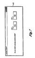
- FIGURE 7 portrays a dialog box 121 presented to the user in the event that the selected cutter is not appropriately sized. If the user wishes to return to that portion of the process to select a different cutter, the user may indicate so by clicking on a button 123. Otherwise, the user may exit the program by selecting the button 125.
Landscapes
- Engineering & Computer Science (AREA)
- Human Computer Interaction (AREA)
- Manufacturing & Machinery (AREA)
- Physics & Mathematics (AREA)
- General Physics & Mathematics (AREA)
- Automation & Control Theory (AREA)
- Numerical Control (AREA)
Abstract
Description
Claims (17)
- A method for utilizing previously sharpened cutters in an automated tool to produce a part, the method comprising:selecting a part for production on an automated tool; selecting a previously-sharpened cutter having a radius and gauge length based upon the radius and gauge length for the cutter;associating the part with the previously sharpened cutter; andgenerating a numeric controlled cutting program based upon the part and the radius and gauge length of the associated previously sharpened cutter.
- The method of Claim 1, wherein generating a numeric controlled cutting program includes running the generated numeric controlled cutting program on the automated tool.
- The method of Claim 1 or 2, wherein selecting a part for production includes selecting a previously-associated numeric model of the part.
- The method of Claim 1, 2 or 3, wherein the numeric controlled cutting program is generated by a CAD/CAM program.
- The method of Claim 4, wherein the CAD/CAM program includes a commercial off-the-shelf program.
- The method according to any of Claims 1-5, wherein the method further includes fabricating the part.
- A software product for commencing an executable instruction set directing an automated tool to machine a part, the software product comprising:a user-interface stored at a first addressable memory site within a network, the interface including:a first software component configured to select an identity of a cutter based upon a radius of the cutter, the radius being stored at a second addressable site within the network in association with the identity of the cutter;a second software component configured to select a name of a part for production, a numeric model of the part being stored at a third addressable site within the network in association with the name; anda third software component configured to initiate an executable program for execution on an automated tool, the third software component being stored at a fourth addressable site within the network, the third software component being configured to generate an executable instruction set based upon the selected cutter and associated data set and the selected part and associated numeric model, the third software component being further configured for storing the executable instruction set at a fifth addressable memory site within a network.
- The software product of Claim 7, wherein the user-interface further includes a fourth software component configured to initiate the executable program on the automated tool.
- The software product of Claim 7 or 8, wherein the user-interface further includes a fifth software component configured to receive information from the executable program.
- The software product of Claim 7, 8 or 9, wherein the user interface is configured to display received information.
- The software product of any of Claims 7-10, wherein a method according to any of Claims 1-6 is used.
- A tool for automatically milling a part, the tool comprising:a controllable end effecter with a chuck to accept a cutter with a known radius, the end effecter being configured to mill a part; anda central processing unit electrically coupled to the end effecter such that the central processing unit being configured to control the end effecter, the central processing unit including:an addressable memory;a user-interface stored at a first addressable memory site within the addressable memory, the interface including:a first software component configured to select an identity of the cutter inserted in the chuck based upon a radius of the cutter, the radius being stored at a second addressable site within the addressable memory in association with the identity of the cutter;a second software component configured to select a name of a part for production, a numeric model of the part being stored at a third addressable site within the addressable memory in association with the name; anda third software component configured to initiate an executable program for execution on an automated tool, the third software component being stored at a fourth addressable site within the addressable memory, the third software component being further configured to generate an executable instruction set based upon the selected cutter and associated data set and the selected part and associated numeric model, the third software component storing the executable instruction set at a fifth addressable memory site within the network.
- The tool of Claim 12, wherein the memory sites included sites within an addressable network.
- The tool of Claim 13, wherein the addressable network includes the Internet.
- The tool of Claim 12, 13 or 14, wherein the third software component includes a verification component.
- The tool of Claim 15, wherein the verification component simulates the movement of the end effecter in three-dimensioned space.
- The tool according to any of Claims 12-16, wherein the method according to any of Claims 1-6 and/or the software product according to any of Claims 7-11 is used.
Applications Claiming Priority (2)
| Application Number | Priority Date | Filing Date | Title |
|---|---|---|---|
| US10/346,310 US6895298B2 (en) | 2003-01-17 | 2003-01-17 | Multi-axis cutter diameter compensation for numeric control machine tools |
| US346310 | 2003-01-17 |
Publications (3)
| Publication Number | Publication Date |
|---|---|
| EP1439439A2 true EP1439439A2 (en) | 2004-07-21 |
| EP1439439A3 EP1439439A3 (en) | 2004-12-15 |
| EP1439439B1 EP1439439B1 (en) | 2009-03-18 |
Family
ID=32594876
Family Applications (1)
| Application Number | Title | Priority Date | Filing Date |
|---|---|---|---|
| EP04075098A Expired - Lifetime EP1439439B1 (en) | 2003-01-17 | 2004-01-15 | Multi-axis cutter diameter compensation for numeric control machine tools |
Country Status (3)
| Country | Link |
|---|---|
| US (1) | US6895298B2 (en) |
| EP (1) | EP1439439B1 (en) |
| DE (1) | DE602004020002D1 (en) |
Families Citing this family (2)
| Publication number | Priority date | Publication date | Assignee | Title |
|---|---|---|---|---|
| US7337086B2 (en) * | 2005-10-18 | 2008-02-26 | Honeywell International, Inc. | System and method for combining diagnostic evidences for turbine engine fault detection |
| US8862433B2 (en) | 2010-05-18 | 2014-10-14 | United Technologies Corporation | Partitioning of turbomachine faults |
Family Cites Families (23)
| Publication number | Priority date | Publication date | Assignee | Title |
|---|---|---|---|---|
| US2933244A (en) | 1956-01-27 | 1960-04-19 | Inductosyn Corp | Tool radius correction computer utilizing a resolver |
| US3500150A (en) | 1965-10-24 | 1970-03-10 | Inductosyn Corp | Tool radius offset control for a closed loop multiaxes numerical control system |
| US3482357A (en) | 1965-10-27 | 1969-12-09 | Fujitsu Ltd | Automatically controlled cam grinding system |
| US3621614A (en) | 1968-12-23 | 1971-11-23 | Toyota Central Res & Dev | Cam grinding machine |
| US3685022A (en) * | 1970-07-27 | 1972-08-15 | Rohr Corp | Numerical control machining apparatus programmed for families of cutter sizes |
| US3866179A (en) | 1972-09-22 | 1975-02-11 | Giddings & Lewis | Numerical control with envelope offset and automatic path segment transitions |
| US3866027A (en) * | 1973-05-09 | 1975-02-11 | Bendix Corp | Digital tool size compensation for numerical control |
| US3939330A (en) | 1974-10-10 | 1976-02-17 | Westinghouse Electric Corporation | Vector conversion system |
| US4084243A (en) | 1975-05-19 | 1978-04-11 | Oki Electric Industry Co., Ltd. | Cutter radius compensation system |
| US4109187A (en) | 1975-09-22 | 1978-08-22 | Autonumerics, Inc. | Contour control system including cutter radius compensation |
| DE2847510A1 (en) * | 1978-11-02 | 1980-06-04 | Hueller Hille Gmbh | METHOD FOR CORRECTING THE LENGTHS AND RADIUS OF TOOLS, ESPECIALLY FOR NUMERICALLY CONTROLLED MACHINES WITH POSITION OR TRAVEL MEASURING SYSTEMS BY MEANS OF THE REQUIRED-ACTUAL COMPARISON |
| JPS60127946A (en) * | 1983-12-14 | 1985-07-08 | Fanuc Ltd | Selection of tool for groove-cutting work in automatic programming |
| US5088207A (en) * | 1989-12-13 | 1992-02-18 | Betsill Harry E | True end-to-end electronic saddle micrometer |
| CA2082790A1 (en) * | 1991-12-02 | 1993-06-03 | R. David Hemmerle | Automated maintenance system for computer numerically controlled machines |
| JPH0957579A (en) * | 1995-08-22 | 1997-03-04 | Toshiba Mach Co Ltd | Dynamic tool wear compensation method for NC machine tools |
| US5822207A (en) * | 1996-05-06 | 1998-10-13 | Amadasoft America, Inc. | Apparatus and method for integrating intelligent manufacturing system with expert sheet metal planning and bending system |
| ATE287317T1 (en) * | 1997-03-15 | 2005-02-15 | Makino Milling Machine | PROCESSOR FOR MACHINE PROCESSING |
| US5933353A (en) * | 1997-09-16 | 1999-08-03 | New Focus, Inc. | Method and apparatus for computer aided machining |
| US6292712B1 (en) * | 1998-01-29 | 2001-09-18 | Northrop Grumman Corporation | Computer interface system for a robotic system |
| US20020103557A1 (en) * | 2000-10-04 | 2002-08-01 | Habersham Metal Products Company | Design tool systems and methods, and user interface |
| US6574527B1 (en) * | 2000-10-05 | 2003-06-03 | Kennametal Inc. | Method of selecting a cutting system |
| US20020133264A1 (en) * | 2001-01-26 | 2002-09-19 | New Jersey Institute Of Technology | Virtual reality system for creation of design models and generation of numerically controlled machining trajectories |
| US6704611B2 (en) * | 2001-08-21 | 2004-03-09 | Surfware, Inc. | System and method for rough milling |
-
2003
- 2003-01-17 US US10/346,310 patent/US6895298B2/en not_active Expired - Lifetime
-
2004
- 2004-01-15 EP EP04075098A patent/EP1439439B1/en not_active Expired - Lifetime
- 2004-01-15 DE DE602004020002T patent/DE602004020002D1/en not_active Expired - Lifetime
Also Published As
| Publication number | Publication date |
|---|---|
| US20040143361A1 (en) | 2004-07-22 |
| EP1439439A3 (en) | 2004-12-15 |
| DE602004020002D1 (en) | 2009-04-30 |
| EP1439439B1 (en) | 2009-03-18 |
| US6895298B2 (en) | 2005-05-17 |
Similar Documents
| Publication | Publication Date | Title |
|---|---|---|
| EP4031947B1 (en) | Hybrid additive and subtractive manufacturing | |
| EP3582044B1 (en) | Machining based on strategies selected from a database | |
| US6982731B2 (en) | Method and system for remotely providing user-defined cutting files for CNC robotic tools | |
| CN109670667A (en) | Server and system | |
| KR100244700B1 (en) | Processing Method Using Numerical Control Device | |
| US20210405611A1 (en) | Virtual computerized numerical control machine system and method | |
| Baron et al. | Proposal of the knowledge application environment of calculating operational parameters for conventional machining technology | |
| US6895298B2 (en) | Multi-axis cutter diameter compensation for numeric control machine tools | |
| US20250315020A1 (en) | Machining environment assist system and machining environment assist method | |
| EP1043118A1 (en) | Preparation of tool information database for nc machining and system for managing tools by utilizing the tool information database | |
| US7062351B2 (en) | Clamp avoidance cutter path regeneration | |
| EP1003087B1 (en) | Method to transfer data between a computer assisted design system and a computer assisted manufacturing system, applying such a method and interface between such systems | |
| US11712773B1 (en) | Machine tool operations optimization | |
| JP2023104771A (en) | MACHINE TOOL SYSTEM, TOOL TYPE ESTIMATION METHOD AND FEATURE VALUE EXTRACTION METHOD | |
| JPH05237740A (en) | Plane machining condition determining method in cam system | |
| JP2972048B2 (en) | How to create NC data | |
| JP7475177B2 (en) | Production machinery system, management method and management program | |
| JP2021170159A (en) | Tool path generator and tool path generation method | |
| WO2024257275A1 (en) | Machining proposal table creation device and machining proposal table creation program | |
| JP2599206B2 (en) | Numerical control information creation device | |
| WO2020090058A1 (en) | Processing support system | |
| WO2025079201A1 (en) | Machining proposal table creation device and machining proposal table creation program | |
| WO2025022527A1 (en) | Machining proposal table creation device and machining proposal table creation program | |
| US7409262B2 (en) | System and method for generating milling codes | |
| JP2002297218A (en) | Machine tool production control method |
Legal Events
| Date | Code | Title | Description |
|---|---|---|---|
| PUAI | Public reference made under article 153(3) epc to a published international application that has entered the european phase |
Free format text: ORIGINAL CODE: 0009012 |
|
| AK | Designated contracting states |
Kind code of ref document: A2 Designated state(s): AT BE BG CH CY CZ DE DK EE ES FI FR GB GR HU IE IT LI LU MC NL PT RO SE SI SK TR |
|
| AX | Request for extension of the european patent |
Extension state: AL LT LV MK |
|
| PUAL | Search report despatched |
Free format text: ORIGINAL CODE: 0009013 |
|
| AK | Designated contracting states |
Kind code of ref document: A3 Designated state(s): AT BE BG CH CY CZ DE DK EE ES FI FR GB GR HU IE IT LI LU MC NL PT RO SE SI SK TR |
|
| AX | Request for extension of the european patent |
Extension state: AL LT LV MK |
|
| RIC1 | Information provided on ipc code assigned before grant |
Ipc: 7G 05B 19/4093 A Ipc: 7B 24B 3/02 B |
|
| 17P | Request for examination filed |
Effective date: 20050613 |
|
| AKX | Designation fees paid |
Designated state(s): DE FR GB |
|
| 17Q | First examination report despatched |
Effective date: 20060324 |
|
| GRAP | Despatch of communication of intention to grant a patent |
Free format text: ORIGINAL CODE: EPIDOSNIGR1 |
|
| RAP1 | Party data changed (applicant data changed or rights of an application transferred) |
Owner name: THE BOEING COMPANY |
|
| GRAS | Grant fee paid |
Free format text: ORIGINAL CODE: EPIDOSNIGR3 |
|
| GRAA | (expected) grant |
Free format text: ORIGINAL CODE: 0009210 |
|
| AK | Designated contracting states |
Kind code of ref document: B1 Designated state(s): DE FR GB |
|
| REG | Reference to a national code |
Ref country code: GB Ref legal event code: FG4D |
|
| REF | Corresponds to: |
Ref document number: 602004020002 Country of ref document: DE Date of ref document: 20090430 Kind code of ref document: P |
|
| PLBI | Opposition filed |
Free format text: ORIGINAL CODE: 0009260 |
|
| PLAB | Opposition data, opponent's data or that of the opponent's representative modified |
Free format text: ORIGINAL CODE: 0009299OPPO |
|
| 26 | Opposition filed |
Opponent name: AIRBUS SAS(FR)/ AIRBUS OPERATIONS SAS(FR)/ AIRBUS Effective date: 20091217 |
|
| R26 | Opposition filed (corrected) |
Opponent name: AIRBUS SAS(FR)/ AIRBUS OPERATIONS SAS(FR)/ AIRBUS Effective date: 20091217 |
|
| PLAX | Notice of opposition and request to file observation + time limit sent |
Free format text: ORIGINAL CODE: EPIDOSNOBS2 |
|
| PLAF | Information modified related to communication of a notice of opposition and request to file observations + time limit |
Free format text: ORIGINAL CODE: EPIDOSCOBS2 |
|
| PLBB | Reply of patent proprietor to notice(s) of opposition received |
Free format text: ORIGINAL CODE: EPIDOSNOBS3 |
|
| PLAB | Opposition data, opponent's data or that of the opponent's representative modified |
Free format text: ORIGINAL CODE: 0009299OPPO |
|
| PLBP | Opposition withdrawn |
Free format text: ORIGINAL CODE: 0009264 |
|
| PLBD | Termination of opposition procedure: decision despatched |
Free format text: ORIGINAL CODE: EPIDOSNOPC1 |
|
| PLBM | Termination of opposition procedure: date of legal effect published |
Free format text: ORIGINAL CODE: 0009276 |
|
| 27C | Opposition proceedings terminated |
Effective date: 20120317 |
|
| PLAD | Information related to termination of opposition procedure modified |
Free format text: ORIGINAL CODE: 0009299OPPC |
|
| STAA | Information on the status of an ep patent application or granted ep patent |
Free format text: STATUS: OPPOSITION PROCEDURE CLOSED |
|
| R27C | Opposition proceedings terminated (corrected) |
Effective date: 20130317 |
|
| REG | Reference to a national code |
Ref country code: FR Ref legal event code: PLFP Year of fee payment: 13 |
|
| REG | Reference to a national code |
Ref country code: FR Ref legal event code: PLFP Year of fee payment: 14 |
|
| REG | Reference to a national code |
Ref country code: FR Ref legal event code: PLFP Year of fee payment: 15 |
|
| PGFP | Annual fee paid to national office [announced via postgrant information from national office to epo] |
Ref country code: FR Payment date: 20230125 Year of fee payment: 20 |
|
| PGFP | Annual fee paid to national office [announced via postgrant information from national office to epo] |
Ref country code: GB Payment date: 20230127 Year of fee payment: 20 Ref country code: DE Payment date: 20230127 Year of fee payment: 20 |
|
| P01 | Opt-out of the competence of the unified patent court (upc) registered |
Effective date: 20230503 |
|
| REG | Reference to a national code |
Ref country code: DE Ref legal event code: R071 Ref document number: 602004020002 Country of ref document: DE |
|
| REG | Reference to a national code |
Ref country code: GB Ref legal event code: PE20 Expiry date: 20240114 |
|
| PG25 | Lapsed in a contracting state [announced via postgrant information from national office to epo] |
Ref country code: GB Free format text: LAPSE BECAUSE OF EXPIRATION OF PROTECTION Effective date: 20240114 |