EP1439305A2 - Engine starter for vehicle - Google Patents
Engine starter for vehicle Download PDFInfo
- Publication number
- EP1439305A2 EP1439305A2 EP03030032A EP03030032A EP1439305A2 EP 1439305 A2 EP1439305 A2 EP 1439305A2 EP 03030032 A EP03030032 A EP 03030032A EP 03030032 A EP03030032 A EP 03030032A EP 1439305 A2 EP1439305 A2 EP 1439305A2
- Authority
- EP
- European Patent Office
- Prior art keywords
- gear
- starter
- crankshaft
- lubricating oil
- starter motor
- Prior art date
- Legal status (The legal status is an assumption and is not a legal conclusion. Google has not performed a legal analysis and makes no representation as to the accuracy of the status listed.)
- Withdrawn
Links
Images

Classifications
-
- F—MECHANICAL ENGINEERING; LIGHTING; HEATING; WEAPONS; BLASTING
- F01—MACHINES OR ENGINES IN GENERAL; ENGINE PLANTS IN GENERAL; STEAM ENGINES
- F01M—LUBRICATING OF MACHINES OR ENGINES IN GENERAL; LUBRICATING INTERNAL COMBUSTION ENGINES; CRANKCASE VENTILATING
- F01M5/00—Heating, cooling, or controlling temperature of lubricant; Lubrication means facilitating engine starting
- F01M5/02—Conditioning lubricant for aiding engine starting, e.g. heating
-
- F—MECHANICAL ENGINEERING; LIGHTING; HEATING; WEAPONS; BLASTING
- F02—COMBUSTION ENGINES; HOT-GAS OR COMBUSTION-PRODUCT ENGINE PLANTS
- F02N—STARTING OF COMBUSTION ENGINES; STARTING AIDS FOR SUCH ENGINES, NOT OTHERWISE PROVIDED FOR
- F02N15/00—Other power-operated starting apparatus; Component parts, details, or accessories, not provided for in, or of interest apart from groups F02N5/00 - F02N13/00
- F02N15/02—Gearing between starting-engines and started engines; Engagement or disengagement thereof
- F02N15/022—Gearing between starting-engines and started engines; Engagement or disengagement thereof the starter comprising an intermediate clutch
- F02N15/023—Gearing between starting-engines and started engines; Engagement or disengagement thereof the starter comprising an intermediate clutch of the overrunning type
-
- F—MECHANICAL ENGINEERING; LIGHTING; HEATING; WEAPONS; BLASTING
- F02—COMBUSTION ENGINES; HOT-GAS OR COMBUSTION-PRODUCT ENGINE PLANTS
- F02N—STARTING OF COMBUSTION ENGINES; STARTING AIDS FOR SUCH ENGINES, NOT OTHERWISE PROVIDED FOR
- F02N2250/00—Problems related to engine starting or engine's starting apparatus
- F02N2250/08—Lubrication of starters; Sealing means for starters
Definitions
- the invention relates to an engine starter for a vehicle.
- a type of starter is disclosed in Japanese Patent Laid-Open Publication No. 2000-120514 in which a gear group for a starter system is provided between an output shaft and a crankshaft of a starter motor, and a portion of the gears included in the starter system gear group are constantly meshed to rotate with the crankshaft, due to the provision of a one-way clutch among the starter system gear group.
- each gear of the starter system gear group is arranged such that a crank gear on the crankshaft is positioned at a lowermost position. Therefore, assuming that lubrication is performed by raking up the lubricating oil in the oil pan with the crank gear, the crank gear must be at least in contact with, if not semi- or fully immersed in, the lubricating oil. However, if the crank gear rotating with the crankshaft is at least in contact with the lubricating oil, friction drag between the crank gear and the lubricating oil continuously acts as a resistance to the rotation of the crankshaft, thus increasing engine friction loss.
- an engine starter for a vehicle is equipped with a starter motor; a gear group structured from a plurality of gears, which transmits the rotation of the starter motor to a crankshaft; and clutch means provided between the starter motor and the crankshaft, which permits the transmission of rotation from the starter motor to the crankshaft, but prevents the transmission of rotation from the crankshaft to the starter motor.
- the engine starter for a vehicle is characterized in that a first gear portion, among the plurality of gears structuring the gear group, disposed so as to enable the transmission of rotation from the clutch means to the crankshaft, is provided in a position where no contact is made with a maximum oil level position, which is a position of the crank chamber where lubricating oil is stored for lubricating gears in the gear group when the lubricating oil amount in the crank chamber reaches a predetermined maximum lubricating oil amount.
- gears disposed between the crankshaft and the clutch means rotate with the crankshaft.
- the gears do not come in contact with the lubricating oil at the maximum oil level position of the crank chamber, and thus no friction drag between the gears and the lubricating oil is created. Consequently, an increase in friction loss of the engine can be prevented, because there is no possibility of friction drag being continuously created between the gear group for starting and the lubricating oil during engine operation.
- a gear in the first gear group may be disposed at a position where the tooth top thereof does not reach the maximum oil level position.
- At least one gear of a second gear portion among the plurality of gears structuring the gear group, which is disposed between the starter motor and the clutch means, may be provided in a position where contact is made with a minimum oil level position of the crank chamber which is a position of the crank chamber when the lubricating oil amount in the crank chamber reaches a predetermined minimum lubricating oil amount.
- the gear group may be structured such that rotation of an output shaft of the starter motor is successively decreased and transmitted to the crankshaft, and provided in a position where a starter gear attached to the output shaft of the starter motor comes in contact with the minimum oil level position.
- lubricating oil can be sufficiently raked up through at least the contact of the starter gear with the lubricating oil, if not the semi- or full immersion of the starter gear therein, thus enabling extensive scattering of lubricating oil.
- the first gear portion may be structured with a crank gear provided on the crankshaft, and an intermediate gear provided on a support shaft parallel with the crankshaft, which is provided with the clutch means and meshed with the crank gear
- the second gear portion may be structured with a starter gear attached to the output shaft of the starter motor, and a driven gear provided on the support shaft and meshed with the starter gear.
- the maximum oil level position and the minimum oil level position may be determined based upon restrictions on the vehicle and engine sides, respectively. For example, in the case of a specific component (such as a connecting rod) present in the engine that should not come in contact with the lubricating oil surface, the maximum oil level position is determined such that the component does not contact the lubricating oil surface even when the vehicle is inclined to the maximum extent allowed in the vehicle specification.
- a specific component such as a connecting rod
- the minimum oil level position is determined such that the component is at least in contact with, if not semi- or fully immersed in, the lubricating oil even when the vehicle is inclined to the maximum extent allowed in the vehicle specification.
- the maximum and minimum oil level positions can be determined in consideration of various conditions required due to structural constraints of the engine and the vehicle.
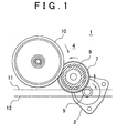
- FIG. 1 is a drawing showing a starter viewed from the direction of an axis of a gear according to an embodiment of the invention.
- FIG. 2 is a drawing showing the starter of FIG. 1 with a partial cutaway in the axial direction of the gear.
- FIGS. 1 and 2 show an engine starter for a vehicle according to an embodiment of the invention.
- the vehicle engine is a reciprocating engine that converts the reciprocating motion of a piston into a rotational motion.
- a starter 1 is equipped with a starter motor 2, and a gear group 4 for transmitting the rotation of the starter motor 2 to an engine crankshaft 3.
- the gear group 4 is equipped with a starter gear 5 driven by an output shaft 2a of the starter motor 2; a driven gear 7 provided so as to mesh with the starter gear 5 on a support shaft 6 provided parallel with the crankshaft 3 and the starter motor 2; an intermediate gear 9 coaxially provided on the support shaft 6 via a one-way clutch 8 serving as clutch means; and a crank gear 10 provided on the crankshaft 3 so as to mesh with the intermediate gear 9.
- the gear ratios between the starter gear 5 and the driven gear 7, and the intermediate gear 9 and the crank gear 10 are set such that rotation of the motor is decrease and transmitted toward the crankshaft 3 side from the output shaft 2a side of the starter motor 2 through the respective gears. Accordingly, the rotation is successively decreased and transmitted to the crankshaft 3 through the gear group 4.
- the driven gear 7 is integrally rotatable with the support shaft 6.
- the one-way clutch 8 transmits rotation from the driven gear 7 to the intermediate gear 9, and prevents the transmission of rotation from the intermediate gear 9 to the driven gear 7.
- the gear group 4 is housed in an oil pan (not shown) provided in the lower portion of a crank chamber of the engine. A maximum oil level position 11 and a minimum oil level position 12 for lubricating oil are set in the oil pan.
- the maximum oil level position 11 and the minimum oil level position 12 are respectively determined by structural constraints of the engine started by the starter 1 or the vehicle in which the starter 1 is installed.
- the maximum oil level position 11 is set such that, for example, a connecting rod that connects the crankshaft 3 and the piston does not contact the lubricating oil.
- the minimum oil level position 12 is set such that, for example, a strainer of a lubricating oil pump disposed at the bottom of the oil pan is semi- or fully immersed in the lubricating oil, even when the vehicle is inclined at a maximum degree within an allowable range.
- other factors including the shape of the engine bottom portion, the position of a gear rotating a balance shaft for negating engine vibration, and the incline of the engine mounted in the vehicle are also considered when determining the maximum oil level position 11 and the minimum oil level position 12.
- Each of the gears 5, 7, 9, and 10 structuring the gear group 4 in the starter 1 are arranged as follows with respect to the maximum oil level position 11 and the minimum oil level position 12 described above.
- the starter gear 5 is disposed such that at least one portion thereof is positioned lower than the minimum oil level position 12.
- a tip diameter of the crank gear 10 is set such that the crank gear 10 is separated above the maximum oil level position 11.
- the shaft core position and the tip diameter of the intermediate gear 9 are respectively set such that the entire gear is separated above the maximum oil level position 11.
- the diameter of the driven gear 7 is set such that the driven gear 7 is coaxial with the intermediate gear 9 and meshes with the starter gear 5.
- the intermediate gear 9 and the crank gear 10 disposed between the one-way clutch 8 and the crankshaft 3 do not come in contact with the lubricating oil surface, even when the oil level of the lubricating oil in the oil pan reaches the maximum oil level position 11.
- the starter gear 5 disposed between the starter motor 2 and the one-way clutch 8 comes in contact with the oil surface of the lubricating oil, even if the oil surface falls to the minimum oil level position 12.
- the lower end of the tip circle of the driven gear 7 is between the maximum oil level position 11 and the minimum oil level position 12, therefore it separates from and is at least in contact with, if not semi- or fully immersed in, the lubricating oil in accordance with changes in the oil level position of the lubricating oil.
- the starter 1 when starting the engine, the rotation of the starter motor 2 is successively transmitted to the starter gear 5, the driven gear 7, the one-way clutch 8, the intermediate gear 9, and the crank gear 10 to rotate and drive the crank shaft 3. Since the starter gear 5 rakes up lubricating oil at this time, lubricating oil spatters around the gear group 4 in mist form so that the lubricating oil is also supplied to the intermediate gear 9 and the crank gear 10, which are positioned above the oil level of the lubricating oil. Consequently, it is not necessary to provide a separate mechanism for supplying lubricating oil to the gears 9, 10 in particular. Furthermore, since the starter gear 5 rotates at the highest speed among the gear group 4, the effect of raking up lubricating oil is high, and the lubricating oil can be extensively scattered.
- the crank gear 10 and the intermediate gear 9 continue to be rotated and driven by the crankshaft 3.
- the one-way clutch 8 blocks transmission of that rotation, so that the driven gear 7 and the starter gear 5 are stopped in a manner similar to the output shaft 2a of the starter motor 2. Therefore, even if the starter gear 5 and the driven gear 7 are at least in contact with, if not semi- or fully immersed in, the lubricating oil, friction drag between the gears 5, 7 and the lubricating oil does not act as resistance to the rotation of the crankshaft 3, and there is no possibility of an increase in engine friction loss caused by contact between the gear group 4 and the lubricating oil.
- the invention is not limited to the embodiment described above, and may be implemented in various embodiments.
- the lower end of the tip circle of the driven gear 7 may be arranged lower than the minimum oil level position 12 in place of or in addition to the starter gear 5.
- the lubricating oil can be supplied to each location using the rotation of the gear during starting.
- the arrangement and number of gears structuring the gear group 4 may be modified as appropriate within the scope substantially identical to the technical concept of the invention.
Landscapes
- Engineering & Computer Science (AREA)
- Mechanical Engineering (AREA)
- General Engineering & Computer Science (AREA)
- Chemical & Material Sciences (AREA)
- Combustion & Propulsion (AREA)
- Lubrication Of Internal Combustion Engines (AREA)
- Gear Transmission (AREA)
- General Details Of Gearings (AREA)
Abstract
Description
Claims (6)
- An engine starter (1) for a vehicle comprising a starter motor (2); a gear group (4) structured from a plurality of gears, which transmits a rotation of the starter motor (2) to a crankshaft (3); and clutch means (8) provided between the starter motor (2) and the crankshaft (3), which permits a transmission of rotation from the starter motor (2) to the crankshaft (3), but prevents the transmission of rotation from the crankshaft (3) to the starter motor (2), characterized in that
a first gear portion (9, 10), among the plurality of gears structuring the gear group (4), disposed so as to enable the transmission of rotation from the clutch means (8) to the crankshaft (3), is provided in a position where no contact is made with a maximum oil level position (11), which is a position of the crank chamber where lubricating oil is stored for lubricating gears in the gear group (4) when the lubricating oil amount in the crank chamber reaches a predetermined maximum lubricating oil amount. - The engine starter (1) for a vehicle according to claim 1, characterized in that
a gear among the first gear portion (9, 10) is disposed at a position where a tooth top thereof does not reach the maximum oil level position (11). - The engine starter (1) for a vehicle according to claim 1 or 2, characterized in that
at least one gear of a second gear portion (5, 7), among the plurality of gears structuring the gear group (4), which is disposed so as to enable the transmission of rotation from the starter motor (2) to the clutch means (8), is provided in a position where contact is made with a minimum oil level position (12) which is a position of the crank chamber when the lubricating oil amount in the crank chamber reaches a predetermined minimum lubricating oil amount. - The engine starter (1) for a vehicle according to claim 3, characterized in that
the gear group (4) is structured such that rotation of an output shaft (2a) of the starter motor (2) is successively decreased and transmitted to the crankshaft (3), and provided in a position where a starter gear (5) attached to the output shaft (2a) of the starter motor (2) comes in contact with the minimum oil level position (12). - The engine starter (1) for a vehicle according to claim 3, characterized in that
the first gear portion (9, 10) comprises a crank gear (10) provided on the crankshaft (3), and an intermediate gear (9) provided on a support shaft (6) parallel with the crankshaft (3), which is provided with the clutch means (8) and meshed with the crank gear (10), and
the second gear portion (5, 7) comprises a starter gear (5) attached to the output shaft (2a) of the starter motor (2), and a driven gear (7) provided on the support shaft (6) and meshed with the starter gear (5). - The engine starter (1) for a vehicle according to any one of claims 1 to 5, characterized in that
the maximum oil level position (11) and the minimum oil level position (12) are determined based upon restrictions on the vehicle and engine sides, respectively.
Applications Claiming Priority (2)
| Application Number | Priority Date | Filing Date | Title |
|---|---|---|---|
| JP2003009142 | 2003-01-17 | ||
| JP2003009142A JP2004218591A (en) | 2003-01-17 | 2003-01-17 | Starting device for vehicle engine |
Publications (2)
| Publication Number | Publication Date |
|---|---|
| EP1439305A2 true EP1439305A2 (en) | 2004-07-21 |
| EP1439305A3 EP1439305A3 (en) | 2005-02-23 |
Family
ID=32588553
Family Applications (1)
| Application Number | Title | Priority Date | Filing Date |
|---|---|---|---|
| EP03030032A Withdrawn EP1439305A3 (en) | 2003-01-17 | 2003-12-31 | Engine starter for vehicle |
Country Status (2)
| Country | Link |
|---|---|
| EP (1) | EP1439305A3 (en) |
| JP (1) | JP2004218591A (en) |
Cited By (2)
| Publication number | Priority date | Publication date | Assignee | Title |
|---|---|---|---|---|
| WO2006016668A1 (en) | 2004-08-09 | 2006-02-16 | Toyota Jidosha Kabushiki Kaisha | Starting apparatus |
| FR2922605A1 (en) * | 2007-10-22 | 2009-04-24 | Skf Ab | DEBRAYABLE MODULE FOR A SYSTEM FOR TRANSMITTING A STARTING TORQUE TO AN INTERNAL COMBUSTION ENGINE |
Family Cites Families (4)
| Publication number | Priority date | Publication date | Assignee | Title |
|---|---|---|---|---|
| FR2456881A1 (en) * | 1979-05-18 | 1980-12-12 | Honda Motor Co Ltd | AUTOMATIC TRANSMISSION COMPRISING A PLANETARY DRIVE AND A CENTRIFUGAL CLUTCH WITH OIL BATH |
| JPH0794803B2 (en) * | 1990-08-01 | 1995-10-11 | 本田技研工業株式会社 | Lubricating oil passage structure of engine equipped with horizontal cylinder and outboard motor equipped with the engine |
| US5992355A (en) * | 1996-10-24 | 1999-11-30 | Honda Giken Kogyo Kabushiki Kaisha | Power unit of a saddle-seat vehicle |
| JP3154693B2 (en) * | 1998-10-14 | 2001-04-09 | 川崎重工業株式会社 | Starting device for vehicle engine |
-
2003
- 2003-01-17 JP JP2003009142A patent/JP2004218591A/en active Pending
- 2003-12-31 EP EP03030032A patent/EP1439305A3/en not_active Withdrawn
Cited By (6)
| Publication number | Priority date | Publication date | Assignee | Title |
|---|---|---|---|---|
| WO2006016668A1 (en) | 2004-08-09 | 2006-02-16 | Toyota Jidosha Kabushiki Kaisha | Starting apparatus |
| US7472672B2 (en) | 2004-08-09 | 2009-01-06 | Toyota Jidosha Kabushiki Kaisha | Starting apparatus |
| CN100590314C (en) * | 2004-08-09 | 2010-02-17 | 丰田自动车株式会社 | starter |
| FR2922605A1 (en) * | 2007-10-22 | 2009-04-24 | Skf Ab | DEBRAYABLE MODULE FOR A SYSTEM FOR TRANSMITTING A STARTING TORQUE TO AN INTERNAL COMBUSTION ENGINE |
| WO2009053276A1 (en) * | 2007-10-22 | 2009-04-30 | Aktiebolaget Skf | Disengageable module for a system for transmitting a starting torque to an internal combustion engine |
| US8464680B2 (en) | 2007-10-22 | 2013-06-18 | Aktiebolaget Skf | Disengageable module for a system for transmitting a starting torque to an internal combustion engine |
Also Published As
| Publication number | Publication date |
|---|---|
| JP2004218591A (en) | 2004-08-05 |
| EP1439305A3 (en) | 2005-02-23 |
Similar Documents
| Publication | Publication Date | Title |
|---|---|---|
| CN101233314B (en) | Starting torque transmission mechanism of internal combustion engine | |
| US9279363B2 (en) | Reciprocating piston mechanism | |
| US8302506B2 (en) | Power transmission device | |
| EP1813839A2 (en) | Positive lubrication of a meshing gear | |
| EP1571309B1 (en) | Power unit for saddle-ride type vehicle | |
| CN1690474A (en) | V-belt automatic transmission | |
| EP1439305A2 (en) | Engine starter for vehicle | |
| CA2542028C (en) | Internal combustion engine with torque converter | |
| CN101292100B (en) | Power train mechanism | |
| JP2008175137A (en) | Engine balancer equipment | |
| EP2017499B1 (en) | Engine | |
| CN1532378A (en) | OHV engine | |
| US7779727B2 (en) | Power unit case configured to house both an engine and a transmission, and power unit including same | |
| CN100526676C (en) | Marine propulsion machine having drive shaft | |
| JPH0533686Y2 (en) | ||
| US7201131B2 (en) | Crankcase cover plate | |
| CN1113159C (en) | V-shape internal combustion engine for vehicle | |
| JP5373526B2 (en) | Crankcase structure of internal combustion engine | |
| TWI871026B (en) | Engine with balancing device | |
| CN1755168A (en) | Transmissions for Small Vehicles | |
| EP0907042A2 (en) | Power transmission for an engine | |
| US20080053397A1 (en) | Mounting structure for supporting a starter motor on an internal combustion engine, and engine including same | |
| JP2605001B2 (en) | Lubrication device for two-stroke internal combustion engine | |
| JPH0536972Y2 (en) | ||
| CN110274006A (en) | Vehicle propulsion system |
Legal Events
| Date | Code | Title | Description |
|---|---|---|---|
| PUAI | Public reference made under article 153(3) epc to a published international application that has entered the european phase |
Free format text: ORIGINAL CODE: 0009012 |
|
| 17P | Request for examination filed |
Effective date: 20031231 |
|
| AK | Designated contracting states |
Kind code of ref document: A2 Designated state(s): AT BE BG CH CY CZ DE DK EE ES FI FR GB GR HU IE IT LI LU MC NL PT RO SE SI SK TR |
|
| AX | Request for extension of the european patent |
Extension state: AL LT LV MK |
|
| PUAL | Search report despatched |
Free format text: ORIGINAL CODE: 0009013 |
|
| AK | Designated contracting states |
Kind code of ref document: A3 Designated state(s): AT BE BG CH CY CZ DE DK EE ES FI FR GB GR HU IE IT LI LU MC NL PT RO SE SI SK TR |
|
| AX | Request for extension of the european patent |
Extension state: AL LT LV MK |
|
| RIC1 | Information provided on ipc code assigned before grant |
Ipc: 7F 01M 9/06 B Ipc: 7F 02N 11/00 B Ipc: 7F 02N 15/02 A |
|
| AKX | Designation fees paid |
Designated state(s): DE FR GB IT |
|
| STAA | Information on the status of an ep patent application or granted ep patent |
Free format text: STATUS: THE APPLICATION IS DEEMED TO BE WITHDRAWN |
|
| 18D | Application deemed to be withdrawn |
Effective date: 20050824 |