EP1439267A1 - Chapeau d'ordonnance à pastille magnétisable pour organe de commande hydraulique, organe de commande, procédé de réalisation - Google Patents
Chapeau d'ordonnance à pastille magnétisable pour organe de commande hydraulique, organe de commande, procédé de réalisation Download PDFInfo
- Publication number
- EP1439267A1 EP1439267A1 EP04300021A EP04300021A EP1439267A1 EP 1439267 A1 EP1439267 A1 EP 1439267A1 EP 04300021 A EP04300021 A EP 04300021A EP 04300021 A EP04300021 A EP 04300021A EP 1439267 A1 EP1439267 A1 EP 1439267A1
- Authority
- EP
- European Patent Office
- Prior art keywords
- cap
- square
- prescription
- housing
- rotation
- Prior art date
- Legal status (The legal status is an assumption and is not a legal conclusion. Google has not performed a legal analysis and makes no representation as to the accuracy of the status listed.)
- Granted
Links
- 238000004519 manufacturing process Methods 0.000 title claims description 7
- 239000000463 material Substances 0.000 claims abstract description 38
- 229910001369 Brass Inorganic materials 0.000 claims abstract description 13
- 239000010951 brass Substances 0.000 claims abstract description 13
- XLYOFNOQVPJJNP-UHFFFAOYSA-N water Substances O XLYOFNOQVPJJNP-UHFFFAOYSA-N 0.000 claims abstract description 12
- 238000009826 distribution Methods 0.000 claims abstract description 11
- 239000008188 pellet Substances 0.000 claims description 29
- 238000002788 crimping Methods 0.000 claims description 14
- 238000005520 cutting process Methods 0.000 claims description 6
- 230000002093 peripheral effect Effects 0.000 claims description 6
- 230000000295 complement effect Effects 0.000 claims description 5
- 229910001220 stainless steel Inorganic materials 0.000 claims description 4
- 239000010935 stainless steel Substances 0.000 claims description 4
- 239000002184 metal Substances 0.000 abstract description 7
- 229910052751 metal Inorganic materials 0.000 abstract description 7
- 238000000034 method Methods 0.000 abstract description 7
- JEIPFZHSYJVQDO-UHFFFAOYSA-N iron(III) oxide Inorganic materials O=[Fe]O[Fe]=O JEIPFZHSYJVQDO-UHFFFAOYSA-N 0.000 abstract 1
- 235000010603 pastilles Nutrition 0.000 description 44
- 239000000523 sample Substances 0.000 description 15
- 230000005291 magnetic effect Effects 0.000 description 9
- 210000000056 organ Anatomy 0.000 description 9
- 230000005415 magnetization Effects 0.000 description 6
- RGWOFTGZWJGPHG-NKWVEPMBSA-N (2r)-3-hydroxy-2-[(1r)-2-oxo-1-(6-oxo-3h-purin-9-yl)ethoxy]propanal Chemical compound N1C=NC(=O)C2=C1N([C@@H](C=O)O[C@H](CO)C=O)C=N2 RGWOFTGZWJGPHG-NKWVEPMBSA-N 0.000 description 5
- 241000897276 Termes Species 0.000 description 5
- 238000005260 corrosion Methods 0.000 description 4
- 239000004033 plastic Substances 0.000 description 4
- 229920003023 plastic Polymers 0.000 description 4
- 229910001018 Cast iron Inorganic materials 0.000 description 3
- 101100230509 Neurospora crassa (strain ATCC 24698 / 74-OR23-1A / CBS 708.71 / DSM 1257 / FGSC 987) hat-1 gene Proteins 0.000 description 3
- 230000007797 corrosion Effects 0.000 description 3
- 230000003068 static effect Effects 0.000 description 3
- 230000004308 accommodation Effects 0.000 description 2
- 230000005540 biological transmission Effects 0.000 description 2
- 239000011248 coating agent Substances 0.000 description 2
- 238000000576 coating method Methods 0.000 description 2
- 239000002131 composite material Substances 0.000 description 2
- 230000006378 damage Effects 0.000 description 2
- 238000000605 extraction Methods 0.000 description 2
- 238000009434 installation Methods 0.000 description 2
- 238000012423 maintenance Methods 0.000 description 2
- 239000003973 paint Substances 0.000 description 2
- 239000004593 Epoxy Substances 0.000 description 1
- 229920002430 Fibre-reinforced plastic Polymers 0.000 description 1
- 229910000831 Steel Inorganic materials 0.000 description 1
- 238000009825 accumulation Methods 0.000 description 1
- 238000013459 approach Methods 0.000 description 1
- 150000001875 compounds Chemical class 0.000 description 1
- 230000002950 deficient Effects 0.000 description 1
- 238000001514 detection method Methods 0.000 description 1
- 230000001627 detrimental effect Effects 0.000 description 1
- 238000005553 drilling Methods 0.000 description 1
- 230000007613 environmental effect Effects 0.000 description 1
- 230000002349 favourable effect Effects 0.000 description 1
- 230000005294 ferromagnetic effect Effects 0.000 description 1
- 239000011151 fibre-reinforced plastic Substances 0.000 description 1
- 238000002955 isolation Methods 0.000 description 1
- 230000004807 localization Effects 0.000 description 1
- 238000003754 machining Methods 0.000 description 1
- 238000012544 monitoring process Methods 0.000 description 1
- 238000004080 punching Methods 0.000 description 1
- 230000001846 repelling effect Effects 0.000 description 1
- 238000011160 research Methods 0.000 description 1
- 230000035945 sensitivity Effects 0.000 description 1
- 239000010959 steel Substances 0.000 description 1
- 239000000126 substance Substances 0.000 description 1
- 239000002699 waste material Substances 0.000 description 1
Images

Classifications
-
- E—FIXED CONSTRUCTIONS
- E03—WATER SUPPLY; SEWERAGE
- E03B—INSTALLATIONS OR METHODS FOR OBTAINING, COLLECTING, OR DISTRIBUTING WATER
- E03B9/00—Methods or installations for drawing-off water
- E03B9/02—Hydrants; Arrangements of valves therein; Keys for hydrants
- E03B9/04—Column hydrants
- E03B9/06—Covers
-
- E—FIXED CONSTRUCTIONS
- E03—WATER SUPPLY; SEWERAGE
- E03B—INSTALLATIONS OR METHODS FOR OBTAINING, COLLECTING, OR DISTRIBUTING WATER
- E03B9/00—Methods or installations for drawing-off water
- E03B9/02—Hydrants; Arrangements of valves therein; Keys for hydrants
-
- E—FIXED CONSTRUCTIONS
- E03—WATER SUPPLY; SEWERAGE
- E03B—INSTALLATIONS OR METHODS FOR OBTAINING, COLLECTING, OR DISTRIBUTING WATER
- E03B9/00—Methods or installations for drawing-off water
- E03B9/02—Hydrants; Arrangements of valves therein; Keys for hydrants
- E03B9/08—Underground hydrants
-
- E—FIXED CONSTRUCTIONS
- E03—WATER SUPPLY; SEWERAGE
- E03B—INSTALLATIONS OR METHODS FOR OBTAINING, COLLECTING, OR DISTRIBUTING WATER
- E03B9/00—Methods or installations for drawing-off water
- E03B9/02—Hydrants; Arrangements of valves therein; Keys for hydrants
- E03B9/08—Underground hydrants
- E03B9/10—Protective plates or covers
Definitions
- the present invention relates to a hat of prescription with magnetizable disc for organ of hydraulic control. It also concerns an organ order with such a prescription hat. She is intended to be used on taps, valves or other distribution network control devices hydraulics and it relates more particularly to their operating devices, in particular operating squares or prescription. It is applicable in particular in industry manufacturing of said control elements and services water distribution.
- the top of these prescription hats forms a maneuver square, also called square drive, exterior, male, standard size which is used to install an operating key with a corresponding female square to transmit the movement and the torque required to control the organ concerned.
- the operating key also called the service key, is generally called a fountain key.
- organ prescription hats underground hydraulics maneuverable from the ground, these organs are placed under a key mouth generally placed at the level of the road network, which covers and closes a tube of mouth with key and a tabernacle allowing its maintenance in relation to the hat.
- these prescription hats are in cast iron, magnetizable material and they are accordingly generally coated with a paint-like coating (epoxy compound for example) for corrosion resistance.
- the color of the paint affixed to the hats is used for mark the direction of closing the valve and it is not possible to mark the closing direction without differentiate the closure caps on the left or right.
- a square is provided female, intaglio, on the upper part of the square male cap maneuver in order to insert and fix it, if necessary, a first end of a maneuvering extension or extension comprising at its second end, which is free, a square for maneuvering the same type as that of the hat.
- a plug for example in plastic, can be placed in the female square with marking of the direction of closing of the tap, such as impose the standards for tap fittings.
- Listening can be performed remotely from the network, by surface, by sensitive microphones allowing an approach overall but which is penalized by low sensitivity and bothered by extraneous noise from the environment.
- the most effective method is to put in contact acoustic probes on different points of the network.
- the acoustic conduction of metal parts of organs hydraulic allows very good transmission of noise and precise location of leaks.
- the keyed mouth heads allow access to the prescription caps on which are placed respondents.
- the probes are with contact magnets to fix them by magnetization to hats.
- the cast prescription caps on which the probes magnets can attach present however several disadvantages.
- the foundry process which allows carrying them out does not ensure very reliable odds keeping and relatively large rejects are generated following a impossible fitting of the cap on the tap or of a set too important.
- the relative positioning of the hat with respect to the tap may vary and, being given that the hat supports stops most of the time in rotation of the shutter member, the open positions and closed taps are not always properly secured. These positioning errors are very detrimental for the takeover operations which consist in piercing the pressurized lines through valves.
- the cast iron requires an anti-corrosion coating of the paint type, which increases the cost of manufacturing the hat.
- caps which are made of stamped brass and which have means for fixing by magnetization hat probes. This solution allows in addition to enhance the appearance of products without resorting to additional corrosion protection operations.
- the stamping is preferably carried out hot.
- the invention therefore relates to a prescription hat for hydraulic network control unit water distribution, in particular valve or tap, the cap comprising an external operating square (male square) being intended to be actuated in rotation about an axis of rotation by an independent and removable square hollow key type of complementary fountain key coming in covering of the external operating square.
- an external operating square male square
- the hat is made of a material not magnetizable, the upper part of the outer square of maneuver comprising a hollow housing open towards the top and a pad in a magnetizable material is disposed and fixed in said housing.
- the term “no magnetizable” means that the material is not attracted by a magnetic field or insufficiently attracted to it remain stable, a magnet not fixing on said material, an example of such a non-magnetizable material is brass or plastics.
- magnetizable means, as opposed to the previous case, that the material is attracted by a magnetic field, a magnet attaching to said material and this, whether there is remanent magnetization or not of the material, an example of such a magnetizable material is a ferromagnetic substance.
- the invention also relates to a hydraulic control with a prescription cap.
- the hat of the organ of order is according to one or more, in combination, of the previous characteristics.
- this one is a tap to take charge on a hydraulic line.
- the invention finally relates to a method of making a prescription hat for the control unit water distribution system hydraulics, in particular valve or tap, the cap having an outer square being intended to be actuated in rotation around an axis of rotation by an independent square hollow key and removable as a complementary fountain key type covering the outer operating square.
- the method to obtain the hat according to one any of the foregoing features and in all their technically possible combinations, on the one hand, we takes a non-magnetizable material and we make a shape hat with in the upper part of the square maneuvering exterior at least one open recess upward in said non-magnetizable material, on the other part, a pellet is produced in a magnetizable material, and the tablet is placed and fixed in the housing.
- the brass hat of the invention has good corrosion resistance while like the metallic pad which is in a stainless steel or INOX sensitive to the static magnetic field of a magnet.
- INOX is of a particular magnetic shade but common, especially in INOX 330 (Z8C17).
- the tablet is preferably made by stamping cutting with reduced cost price.
- the tablet can be marked with stamping to identify the direction of operation of the tap. This marking is carried out during the operations of cutting and stamping the washer, at a cost negligible additional.
- the fitting of the patch in the hat by crimping allows disassembly to allow use of the female square with an extension.
- a central hole is made in the tablet to be able to slide a disassembly tool into it and leverage.
- the hole of the metal pad allows, firstly, to position the crimping tool by compared to the pellet and significantly facilitates the implementation, second, to avoid the "pump" phenomenon created by the air trapped under the tablet during installation and crimping of said pellet and, thirdly, as has been indicated, to slide a tool to disassemble this pad easily by exerting leverage.
- At least one opening can also be provided laterally, as an alternative or not from the central opening.
- crimping position characteristics of crimping previously listed are indicative as it is possible to obtain support (resistance to the attraction of magnet) and disassembly possibilities (force to provide for extract the tablet) equivalent with different positions, lengths and number of zones of crimping.
- the crimping can therefore be complete, i.e. on the whole periphery of the patch or only in certain areas, preferably regularly distributed over the periphery of the patch.
- the tablet is a circular metal washer just like its housing which removes all orientation constraints.
- the positioning of the pellet is made in a counterbore made in rough stamping or following machining of the cap.
- the tablet is set in the counterbore (raw or machined) of the brass cap by strikes, classic "industrial" system, with a set cost barely higher than fitting the plug traditional plastic.
- the crimping of the wafer is preferably carried out on small areas and not on the total circumference thereof, which minimizes the effort necessary crimping while maintaining greater than the attraction forces generated by the magnets probes while allowing disassembly of the washer.
- the present invention provides an advantage additional by better positioning on the Magnetic acoustic probe scheduling cap of fixation. Indeed, in the case of a traditional hat in cast iron, the magnet can be fixed on the whole mass metallic and therefore not necessarily on a very flat part. On the contrary, with the pellet which is of reduced size and positioned in an area favorable to good contact probe cap for good wave transmission noise, this risk of defective fixing is eliminated.
- the metal pellet is curved, which allows to bring its upper surface closer to the top of the cap, thereby improving cap-probe contact and magnetization phenomenon, while preserving the possibility of crimp the disc into the brass cap.
- the height of the tablet is entered and removing the counterbore from the hat to provide a space for material above the washer which can be folded over this and thus ensure its crimping.
- this curved surface towards the top of the patch avoids or limits the accumulation of earth or other foreign debris on the top surface of the hat that could alter the contact between the probe and the prescription cap.
- the invention is preferably implemented in hydraulic control members of a network of water distribution and in particular in its related part with users.
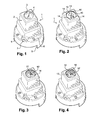
- a prescription hat 1 with a counterbore housing 3 extending by a female square 4 is seen in perspective.
- Hat 1 is made of brass.
- the upper part of the hat 1 forms the operating square 2 exterior, male, which has an upper surface with the recess 3 in circular recess whose plunging edge forms a counterbore. Housing continues down, in the depth of the cap 1 by a female square 4.
- the middle part of the hat has a double projection of which the lower 6 bears markers, D and G in this production.
- the form of the middle part can be different.
- the lower part of the tubular hat cylindrical has a notch whose edges 5 allow to realize rotational stops, the cap being actuated in rotation driving a command a hydraulic member not shown and on which is normally placed the cap, the hydraulic member having a corresponding lug intended to come against one of the stops 5 depending on the open or closed position of the control.
- the stop system can be carried out according to other known methods.
- the inner part of the hat presents suitable structural characteristics in the drive of the control of the hydraulic member, in generally an axis, and in particular means for fixing the hat with the command of which one sees the orifice 7 threaded intended to receive a locking screw for fixing the bonnet on the order.
- the command is a square axis with a corner is a cutaway, the opening 7 opening inside the hat on the corner opposite the cut plane.
- means of fixing a possible extension are preferably designed to fix the extension in the square female, said fastening means having not been shown here to avoid cluttering Figure 1.
- These fixing means can in particular be a passage threaded for screwing an extension clamp screw or a drilling for the installation of a pin.
- Figure 2 corresponds to the prescription hat of the Figure 1 but with a flat pad 10 crimped in the housing 3.
- the pellet is a washer, the housing being circular.
- the patch is set in four zones 14 evenly distributed over the periphery of the patch.
- the patch has an orifice 11 or central hole and a marking 12 direction of rotation. The opening allows, among other things, forcibly extract the tablet in case an extension must be placed in the female square 4.
- Figure 3 corresponds to the prescription hat of the Figure 1 but with a 10 'curved disc set in the housing 3.
- the pellet is a washer, the housing being circular.
- the patch is set in four zones 14 evenly distributed over the periphery of the patch.
- the patch has an orifice 11 or central hole and a marking 12 direction of rotation.
- the orifice allows the force to be extracted tablet if an extension is to be placed in the square female 4.
- the bulge makes it possible to bring together and even, in the example shown, to go beyond the upper plane of the operating square 2, the pellet being overflowing.
- Figure 4 corresponds to the prescription cap of the Figure 3 but with a 10 'curved disc, with notch peripheral 13, crimped in the housing 3.
- the notch 13 facilitates the extraction by force of the pellet by compared to the use of the central orifice 11.
- Figures 5a and 5b respectively represent a flat tablet 10 top view and the same tablet 10 view laterally.
- the pad which is here a washer has a central hole 11 and a marking 12 of at least the direction of rotation.
- Figures 6a and 6b respectively represent a 10 'curved tablet viewed from above and the same tablet convex 10 'seen laterally.
- the tablet which is here a washer has a central hole 11 and a marking 12 at least the direction of rotation.
- the curved tablet seen from above in Figure 7 has a peripheral notch 13 intended to facilitate the extraction of the pellet set in the cap.
- the cross section of the curved tablet 10 ′ in FIG. 8 is axial and passes through the central orifice 11.
- a pattern 12 produced by stamping / punching is visible hollow on the surface top of the pellet.
- the axial section in Figure 9 shows the inner and lower part of the cap, the housing 8 of maneuver, not visible in the other figures and which is adapted to receive in fixation the command of the organ hydraulics on which the hat is placed.
- a way of fixing of the hat to the control is also visible in the form of an orifice 7 for the passage of a locking screw not shown here.
- the housing 8 of the operation at the orifice 7 appears not symmetrical and axial because the cut goes through a cutaway 9 of the housing 8 of the cap 1 corresponding to the cutaway of the maneuver that must come into the accommodation.
Landscapes
- Health & Medical Sciences (AREA)
- Life Sciences & Earth Sciences (AREA)
- Engineering & Computer Science (AREA)
- Hydrology & Water Resources (AREA)
- Public Health (AREA)
- Water Supply & Treatment (AREA)
- Toys (AREA)
- Domestic Plumbing Installations (AREA)
- Vehicle Waterproofing, Decoration, And Sanitation Devices (AREA)
- Shaping Metal By Deep-Drawing, Or The Like (AREA)
- Prostheses (AREA)
- Finishing Walls (AREA)
- Fluid-Pressure Circuits (AREA)
- Actuator (AREA)
- Medicinal Preparation (AREA)
- Closures For Containers (AREA)
Abstract
Description
- le logement comporte un bord périphérique lamé destiné à la réalisation d'un sertissage,
- la pastille est sertie dans le logement,
- le logement est circulaire,
- la pastille est une rondelle circulaire,
- la pastille comporte au moins un orifice,
(l'orifice traverse la pastille de part en part) - la pastille comporte au moins un orifice central,
- la pastille comporte au moins un orifice latéral,
- l'orifice latéral est une encoche sur la périphérie de la pastille,
- la pastille est plate,
- la pastille est bombée,
- la pastille est bombée et la surface supérieure de la pastille
présente une zone de surface plane,
(le terme surface supérieure correspond à la partie de la pastille la plus haute et surélevée du bombement) - la pastille est bombée et la surface supérieure de la pastille
est en dessous du plan général de la surface supérieure du
chapeau,
(en d'autres termes, la pastille ne dépasse pas du chapeau) - la pastille est bombée et la surface supérieure de la pastille est dans le plan général de la surface supérieure du chapeau, (en d'autres termes, la pastille est affleurante de la partie supérieure du chapeau)
- la pastille est bombée et la surface supérieure de la pastille
est au-dessus du plan général de la surface supérieure du
chapeau,
(en d'autres termes, la pastille dépasse du chapeau ou une partie au moins de la surface supérieure de la pastille se trouve au-dessus du point le plus haut du chapeau), - de préférence, la pastille est bombée et la surface supérieure de la pastille est au-dessus du plan général de la surface supérieure du chapeau,
- le logement de pastille se prolonge dans le chapeau par un carré intérieur en creux (femelle),
- la pastille ayant été retirée, le carré intérieur comporte un prolongateur de manoeuvre inséré rapporté solidarisé au chapeau d'ordonnance, l'extrémité libre dudit prolongateur comportant un carré extérieur destiné à être actionné en rotation par une clé creuse carrée indépendante et amovible de type clé de fontainier complémentaire venant en recouvrement dudit carré extérieur du prolongateur,
- la pastille est circulaire dans un logement circulaire coaxial à l'axe de rotation et le sertissage est disposé en au moins trois zones équidistantes angulairement par rapport à l'axe de rotation,
- le sertissage est disposé en quatre zones équidistantes angulairement par rapport à l'axe de rotation,
- la pastille est magnétisée (en d'autres termes, la pastille est un aimant), l'orientation du champ magnétique de la pastille attirant les aimants des sondes compatibles et repoussant ceux des sondes incompatibles,
- la pastille est obtenue par découpe et emboutissage d'une plaque d'un matériau magnétisable,
- de préférence, le matériau magnétisable ne présente pas d'aimantation résiduelle après avoir été soumis à un champ magnétique statique,
- de préférence, le matériau magnétisable présente une aimantation résiduelle négligeable après avoir été soumis à un champ magnétique statique (c'est-à-dire qu'il ne perturbera pas la fixation ultérieure d'une sonde),
- le chapeau est en métal non magnétisable,
- le chapeau est en laiton,
- le chapeau est en matière plastique,
- le chapeau est en matière plastique renforcée de fibres,
- le chapeau est en matériau composite,
- le chapeau est obtenu par matriçage à chaud avec la matière non magnétisable qui est du laiton,
- la matière non magnétisable du chapeau est du laiton et le matériau magnétisable de la pastille est de l'acier inoxydable magnétisable,
- la pastille est en INOX 330 (Z8C17),
- le chapeau est obtenu par matriçage à chaud avec la matière non magnétisable et la pastille est obtenue par découpe et emboutissage d'une plaque d'un matériau magnétisable,
- la pastille comporte un marquage,
- le marquage de la pastille est réalisé lors de l'emboutissage,
- le marquage indique au moins le sens de rotation du chapeau de l'organe.
Claims (11)
- Chapeau d'ordonnance (1) pour organe de commande hydraulique de réseau de distribution d'eau, notamment vanne ou robinet, le chapeau comportant un carré extérieur (2) de manoeuvre étant destiné à être actionné en rotation autour d'un axe de rotation par une clé creuse carrée indépendante et amovible de type clé de fontainier complémentaire venant en recouvrement du carré extérieur de manoeuvre,
caractérisé en ce que le chapeau est dans une matière non magnétisable, la partie supérieure du carré extérieur (2) de manoeuvre comportant un logement (3) en creux ouvert vers le haut et en ce qu'une pastille (10,10') dans un matériau magnétisable est disposée et fixée dans ledit logement. - Chapeau d'ordonnance selon la revendication 1, caractérisé en ce que le logement comporte un bord périphérique lamé destiné à la réalisation d'un sertissage et en ce que la pastille (10,10') est sertie (14) dans le logement.
- Chapeau d'ordonnance selon la revendication 1 ou 2, caractérisé en ce que la pastille (10,10') comporte un orifice central.
- Chapeau d'ordonnance selon la revendication 1,2 ou 3, caractérisé en ce que la pastille (10') est bombée.
- Chapeau d'ordonnance selon la revendication 4, caractérisé en ce qu'une partie au moins de la surface supérieure de la pastille se trouve au-dessus du point le plus haut du chapeau.
- Chapeau d'ordonnance selon l'une quelconque des revendications précédentes, caractérisé en ce que le logement (3) de pastille se prolonge dans le chapeau par un carré femelle (4) intérieur en creux.
- Chapeau d'ordonnance selon l'une quelconque des revendications précédentes, caractérisé en ce que la pastille est circulaire dans un logement circulaire coaxial à l'axe de rotation et en ce que le sertissage est disposé en au moins trois zones équidistantes angulairement par rapport à l'axe de rotation.
- Chapeau d'ordonnance selon l'une quelconque des revendications précédentes, caractérisée en ce que la matière non magnétisable du chapeau est du laiton et en ce que le matériau magnétisable de la pastille est de l'acier inoxydable magnétisable.
- Organe de commande hydraulique de réseau de distribution d'eau, notamment vanne ou robinet, avec chapeau d'ordonnance comportant un carré extérieur de manoeuvre destiné à être actionné en rotation autour d'un axe de rotation par une clé creuse carrée indépendante et amovible de type clé de fontainier complémentaire venant en recouvrement du carré extérieur de manoeuvre, caractérisé en ce que le chapeau est dans une matière non magnétisable, la partie supérieure du carré extérieur de manoeuvre comportant un logement en creux ouvert vers le haut et en ce qu'une pastille dans un matériau magnétisable est disposée fixée dans ledit logement.
- Procédé de réalisation d'un chapeau d'ordonnance pour organe de commande hydraulique de réseau de distribution d'eau, notamment vanne ou robinet, le chapeau comportant un carré extérieur de manoeuvre étant destiné à être actionné en rotation autour d'un axe de rotation par une clé creuse carrée indépendante et amovible de type clé de fontainier complémentaire venant en recouvrement du carré extérieur de manoeuvre, caractérisé en ce que pour obtenir le chapeau selon l'une quelconque des revendications 1 à 8, d'une part, on prend une matière non magnétisable et on réalise une forme de chapeau comportant dans la partie supérieure du carré extérieur de manoeuvre au moins un logement en creux ouvert vers le haut dans ladite matière non magnétisable, d'autre part, on réalise dans un matériau magnétisable une pastille métallique, et on dispose et fixe la pastille dans le logement.
- Procédé de réalisation d'un chapeau d'ordonnance selon la revendication 10, caractérisé en ce que l'on prend une matière non magnétisable qui est du laiton et que l'on travaille par matriçage à chaud pour réaliser la forme de chapeau, et en ce que l'on réalise la pastille par découpe emboutissage d'une feuille d'un matériau magnétisable qui est de l'acier inoxydable magnétisable.
Applications Claiming Priority (2)
| Application Number | Priority Date | Filing Date | Title |
|---|---|---|---|
| FR0300357A FR2849879B1 (fr) | 2003-01-14 | 2003-01-14 | Chapeau d'ordonnance a pastille magnetisable pour organe de commande hydraulique, organe de commande, procede de realisation |
| FR0300357 | 2003-01-14 |
Publications (2)
| Publication Number | Publication Date |
|---|---|
| EP1439267A1 true EP1439267A1 (fr) | 2004-07-21 |
| EP1439267B1 EP1439267B1 (fr) | 2007-07-04 |
Family
ID=32524903
Family Applications (1)
| Application Number | Title | Priority Date | Filing Date |
|---|---|---|---|
| EP04300021A Expired - Lifetime EP1439267B1 (fr) | 2003-01-14 | 2004-01-14 | Chapeau d'ordonnance à pastille magnétisable pour organe de commande hydraulique, organe de commande, procédé de réalisation |
Country Status (5)
| Country | Link |
|---|---|
| EP (1) | EP1439267B1 (fr) |
| AT (1) | ATE366339T1 (fr) |
| DE (1) | DE602004007305D1 (fr) |
| ES (1) | ES2228303T3 (fr) |
| FR (1) | FR2849879B1 (fr) |
Cited By (1)
| Publication number | Priority date | Publication date | Assignee | Title |
|---|---|---|---|---|
| FR2970271A1 (fr) * | 2011-01-10 | 2012-07-13 | Sainte Lizaigne Sa | Chapeau d'ordonnance a pastille d'identification radiofrequence pour organe hydraulique manoeuvrable, organes hydrauliques manoeuvrable et de controle |
Families Citing this family (1)
| Publication number | Priority date | Publication date | Assignee | Title |
|---|---|---|---|---|
| DE102004061168B4 (de) | 2004-12-16 | 2023-02-16 | Schönborner Armaturen GmbH | Einbaugarnitur |
Citations (4)
| Publication number | Priority date | Publication date | Assignee | Title |
|---|---|---|---|---|
| US3267957A (en) * | 1964-07-13 | 1966-08-23 | Joseph T Glennon | Gas valve service boxes which are ventilated and offer chimney-action for escaping gas |
| FR1499373A (fr) * | 1966-09-08 | 1967-10-27 | Bayard & Ses Fils C | Perfectionnements aux robinets de branchement, notamment pour la distribution des eaux |
| US5205312A (en) * | 1992-06-02 | 1993-04-27 | Magna-Loc Valve Corp. | Fire hydrant locking arrangement |
| US5596893A (en) * | 1995-12-28 | 1997-01-28 | Hydra-Shield Manufacturing, Inc. | Devices for securing fire hydrant valves |
-
2003
- 2003-01-14 FR FR0300357A patent/FR2849879B1/fr not_active Expired - Fee Related
-
2004
- 2004-01-14 DE DE602004007305T patent/DE602004007305D1/de not_active Expired - Lifetime
- 2004-01-14 EP EP04300021A patent/EP1439267B1/fr not_active Expired - Lifetime
- 2004-01-14 ES ES04300021T patent/ES2228303T3/es not_active Expired - Lifetime
- 2004-01-14 AT AT04300021T patent/ATE366339T1/de not_active IP Right Cessation
Patent Citations (4)
| Publication number | Priority date | Publication date | Assignee | Title |
|---|---|---|---|---|
| US3267957A (en) * | 1964-07-13 | 1966-08-23 | Joseph T Glennon | Gas valve service boxes which are ventilated and offer chimney-action for escaping gas |
| FR1499373A (fr) * | 1966-09-08 | 1967-10-27 | Bayard & Ses Fils C | Perfectionnements aux robinets de branchement, notamment pour la distribution des eaux |
| US5205312A (en) * | 1992-06-02 | 1993-04-27 | Magna-Loc Valve Corp. | Fire hydrant locking arrangement |
| US5596893A (en) * | 1995-12-28 | 1997-01-28 | Hydra-Shield Manufacturing, Inc. | Devices for securing fire hydrant valves |
Cited By (1)
| Publication number | Priority date | Publication date | Assignee | Title |
|---|---|---|---|---|
| FR2970271A1 (fr) * | 2011-01-10 | 2012-07-13 | Sainte Lizaigne Sa | Chapeau d'ordonnance a pastille d'identification radiofrequence pour organe hydraulique manoeuvrable, organes hydrauliques manoeuvrable et de controle |
Also Published As
| Publication number | Publication date |
|---|---|
| ATE366339T1 (de) | 2007-07-15 |
| ES2228303T1 (es) | 2005-04-16 |
| FR2849879B1 (fr) | 2005-12-09 |
| EP1439267B1 (fr) | 2007-07-04 |
| FR2849879A1 (fr) | 2004-07-16 |
| DE602004007305D1 (de) | 2007-08-16 |
| ES2228303T3 (es) | 2008-01-01 |
Similar Documents
| Publication | Publication Date | Title |
|---|---|---|
| EP0008964B1 (fr) | Procédé d'obtention d'un corps creux monobloc par soufflage et corps creux obtenu | |
| FR2827364A1 (fr) | Connecteur rapide | |
| US9273453B2 (en) | Drain clean-out assembly and method of using | |
| EP1439267B1 (fr) | Chapeau d'ordonnance à pastille magnétisable pour organe de commande hydraulique, organe de commande, procédé de réalisation | |
| EP1489713B1 (fr) | Dispositif de traversée étanche de paroi | |
| EP2247799A2 (fr) | Dispositif de montage et de raccordement de conduites d'installations sanitaires prevues en arriere d'une paroi et procede correspondant | |
| EP1343995A1 (fr) | Coupleur rapide avec temoin de connexion | |
| EP1596116B1 (fr) | Bague de visualisation du sertissage d'un raccord pour tubes | |
| FR2970271A1 (fr) | Chapeau d'ordonnance a pastille d'identification radiofrequence pour organe hydraulique manoeuvrable, organes hydrauliques manoeuvrable et de controle | |
| US11486799B2 (en) | Device for use with measuring soil gas and method of use | |
| CA2675090A1 (fr) | Ensemble de nettoyage de drain et sa methode d'utilisation | |
| EP4042058B1 (fr) | Dispositif d'obturation d'un conduit muni d'un appareil de mesure comprenant un emetteur | |
| FR2985631A1 (fr) | Boitier pour dispositif electronique | |
| EP2412602B1 (fr) | Dispositif de verrouillage d'aiguillage ferroviaire | |
| EP0277898A1 (fr) | Boîtier destiné au passage des fluides sous pression dans la maçonnerie | |
| WO2008071864A2 (fr) | Moyens de fixation d'un element de robinetterie sur une paroi | |
| FR3080124A1 (fr) | Kit de fixation d'un robinet sur une paroi, avec platine, raccord et applique de finition | |
| FR2820487A1 (fr) | Robinet trois voies pour prise en charge sur le cote ou le dessus | |
| EP1649472B1 (fr) | Electrovalve, procede d'assemblage d'un solenoïde sur ladite electrovalve, et procede de desassemblage du solenoïde de ladite electrovalve | |
| EP3479689B1 (fr) | Installation à abreuvoir pour animaux | |
| FR2468711A1 (fr) | Protege-gond | |
| EP1279874B1 (fr) | Procédé de production d'une vanne melangeuse | |
| FR3072245A1 (fr) | Installation a abreuvoir pour animaux | |
| FR3074873A1 (fr) | Element tubulaire et procede de fabrication correspondant | |
| FR2683608A1 (fr) | Dispositif a ouverture et fermeture rapides pour maintenir des objets allonges sur un support. |
Legal Events
| Date | Code | Title | Description |
|---|---|---|---|
| PUAI | Public reference made under article 153(3) epc to a published international application that has entered the european phase |
Free format text: ORIGINAL CODE: 0009012 |
|
| AK | Designated contracting states |
Kind code of ref document: A1 Designated state(s): AT BE BG CH CY CZ DE DK EE ES FI FR GB GR HU IE IT LI LU MC NL PT RO SE SI SK TR |
|
| AX | Request for extension of the european patent |
Extension state: AL LT LV MK |
|
| RIN1 | Information on inventor provided before grant (corrected) |
Inventor name: MURIAS, LIONEL Inventor name: VERHEE, DAMIEN |
|
| 17P | Request for examination filed |
Effective date: 20050121 |
|
| AKX | Designation fees paid |
Designated state(s): AT BE BG CH CY CZ DE DK EE ES FI FR GB GR HU IE IT LI LU MC NL PT RO SE SI SK TR |
|
| GRAP | Despatch of communication of intention to grant a patent |
Free format text: ORIGINAL CODE: EPIDOSNIGR1 |
|
| GRAS | Grant fee paid |
Free format text: ORIGINAL CODE: EPIDOSNIGR3 |
|
| GRAA | (expected) grant |
Free format text: ORIGINAL CODE: 0009210 |
|
| AK | Designated contracting states |
Kind code of ref document: B1 Designated state(s): AT BE BG CH CY CZ DE DK EE ES FI FR GB GR HU IE IT LI LU MC NL PT RO SE SI SK TR |
|
| REG | Reference to a national code |
Ref country code: GB Ref legal event code: FG4D Free format text: NOT ENGLISH |
|
| REG | Reference to a national code |
Ref country code: CH Ref legal event code: EP |
|
| REG | Reference to a national code |
Ref country code: IE Ref legal event code: FG4D Free format text: LANGUAGE OF EP DOCUMENT: FRENCH |
|
| REF | Corresponds to: |
Ref document number: 602004007305 Country of ref document: DE Date of ref document: 20070816 Kind code of ref document: P |
|
| REG | Reference to a national code |
Ref country code: ES Ref legal event code: FG2A Ref document number: 2228303 Country of ref document: ES Kind code of ref document: T3 |
|
| NLV1 | Nl: lapsed or annulled due to failure to fulfill the requirements of art. 29p and 29m of the patents act | ||
| GBV | Gb: ep patent (uk) treated as always having been void in accordance with gb section 77(7)/1977 [no translation filed] |
Effective date: 20070704 |
|
| PG25 | Lapsed in a contracting state [announced via postgrant information from national office to epo] |
Ref country code: SI Free format text: LAPSE BECAUSE OF FAILURE TO SUBMIT A TRANSLATION OF THE DESCRIPTION OR TO PAY THE FEE WITHIN THE PRESCRIBED TIME-LIMIT Effective date: 20070704 Ref country code: NL Free format text: LAPSE BECAUSE OF FAILURE TO SUBMIT A TRANSLATION OF THE DESCRIPTION OR TO PAY THE FEE WITHIN THE PRESCRIBED TIME-LIMIT Effective date: 20070704 Ref country code: PT Free format text: LAPSE BECAUSE OF FAILURE TO SUBMIT A TRANSLATION OF THE DESCRIPTION OR TO PAY THE FEE WITHIN THE PRESCRIBED TIME-LIMIT Effective date: 20071204 Ref country code: FI Free format text: LAPSE BECAUSE OF FAILURE TO SUBMIT A TRANSLATION OF THE DESCRIPTION OR TO PAY THE FEE WITHIN THE PRESCRIBED TIME-LIMIT Effective date: 20070704 Ref country code: BG Free format text: LAPSE BECAUSE OF FAILURE TO SUBMIT A TRANSLATION OF THE DESCRIPTION OR TO PAY THE FEE WITHIN THE PRESCRIBED TIME-LIMIT Effective date: 20071004 |
|
| PG25 | Lapsed in a contracting state [announced via postgrant information from national office to epo] |
Ref country code: AT Free format text: LAPSE BECAUSE OF FAILURE TO SUBMIT A TRANSLATION OF THE DESCRIPTION OR TO PAY THE FEE WITHIN THE PRESCRIBED TIME-LIMIT Effective date: 20070704 |
|
| REG | Reference to a national code |
Ref country code: IE Ref legal event code: FD4D |
|
| PG25 | Lapsed in a contracting state [announced via postgrant information from national office to epo] |
Ref country code: GR Free format text: LAPSE BECAUSE OF FAILURE TO SUBMIT A TRANSLATION OF THE DESCRIPTION OR TO PAY THE FEE WITHIN THE PRESCRIBED TIME-LIMIT Effective date: 20071005 Ref country code: DK Free format text: LAPSE BECAUSE OF FAILURE TO SUBMIT A TRANSLATION OF THE DESCRIPTION OR TO PAY THE FEE WITHIN THE PRESCRIBED TIME-LIMIT Effective date: 20070704 |
|
| PLBE | No opposition filed within time limit |
Free format text: ORIGINAL CODE: 0009261 |
|
| STAA | Information on the status of an ep patent application or granted ep patent |
Free format text: STATUS: NO OPPOSITION FILED WITHIN TIME LIMIT |
|
| PG25 | Lapsed in a contracting state [announced via postgrant information from national office to epo] |
Ref country code: GB Free format text: LAPSE BECAUSE OF FAILURE TO SUBMIT A TRANSLATION OF THE DESCRIPTION OR TO PAY THE FEE WITHIN THE PRESCRIBED TIME-LIMIT Effective date: 20070704 Ref country code: SK Free format text: LAPSE BECAUSE OF FAILURE TO SUBMIT A TRANSLATION OF THE DESCRIPTION OR TO PAY THE FEE WITHIN THE PRESCRIBED TIME-LIMIT Effective date: 20070704 Ref country code: IE Free format text: LAPSE BECAUSE OF FAILURE TO SUBMIT A TRANSLATION OF THE DESCRIPTION OR TO PAY THE FEE WITHIN THE PRESCRIBED TIME-LIMIT Effective date: 20070704 Ref country code: CZ Free format text: LAPSE BECAUSE OF FAILURE TO SUBMIT A TRANSLATION OF THE DESCRIPTION OR TO PAY THE FEE WITHIN THE PRESCRIBED TIME-LIMIT Effective date: 20070704 |
|
| 26N | No opposition filed |
Effective date: 20080407 |
|
| PG25 | Lapsed in a contracting state [announced via postgrant information from national office to epo] |
Ref country code: RO Free format text: LAPSE BECAUSE OF FAILURE TO SUBMIT A TRANSLATION OF THE DESCRIPTION OR TO PAY THE FEE WITHIN THE PRESCRIBED TIME-LIMIT Effective date: 20070704 Ref country code: SE Free format text: LAPSE BECAUSE OF FAILURE TO SUBMIT A TRANSLATION OF THE DESCRIPTION OR TO PAY THE FEE WITHIN THE PRESCRIBED TIME-LIMIT Effective date: 20071004 |
|
| BERE | Be: lapsed |
Owner name: SAINTE LIZAIGNE SA Effective date: 20080131 |
|
| PG25 | Lapsed in a contracting state [announced via postgrant information from national office to epo] |
Ref country code: DE Free format text: LAPSE BECAUSE OF FAILURE TO SUBMIT A TRANSLATION OF THE DESCRIPTION OR TO PAY THE FEE WITHIN THE PRESCRIBED TIME-LIMIT Effective date: 20071005 |
|
| PG25 | Lapsed in a contracting state [announced via postgrant information from national office to epo] |
Ref country code: MC Free format text: LAPSE BECAUSE OF NON-PAYMENT OF DUE FEES Effective date: 20080131 |
|
| REG | Reference to a national code |
Ref country code: CH Ref legal event code: PL |
|
| PG25 | Lapsed in a contracting state [announced via postgrant information from national office to epo] |
Ref country code: CH Free format text: LAPSE BECAUSE OF NON-PAYMENT OF DUE FEES Effective date: 20080131 Ref country code: LI Free format text: LAPSE BECAUSE OF NON-PAYMENT OF DUE FEES Effective date: 20080131 |
|
| PG25 | Lapsed in a contracting state [announced via postgrant information from national office to epo] |
Ref country code: EE Free format text: LAPSE BECAUSE OF FAILURE TO SUBMIT A TRANSLATION OF THE DESCRIPTION OR TO PAY THE FEE WITHIN THE PRESCRIBED TIME-LIMIT Effective date: 20070704 |
|
| PG25 | Lapsed in a contracting state [announced via postgrant information from national office to epo] |
Ref country code: BE Free format text: LAPSE BECAUSE OF NON-PAYMENT OF DUE FEES Effective date: 20080131 |
|
| PG25 | Lapsed in a contracting state [announced via postgrant information from national office to epo] |
Ref country code: CY Free format text: LAPSE BECAUSE OF FAILURE TO SUBMIT A TRANSLATION OF THE DESCRIPTION OR TO PAY THE FEE WITHIN THE PRESCRIBED TIME-LIMIT Effective date: 20070704 |
|
| REG | Reference to a national code |
Ref country code: FR Ref legal event code: CA |
|
| PG25 | Lapsed in a contracting state [announced via postgrant information from national office to epo] |
Ref country code: HU Free format text: LAPSE BECAUSE OF FAILURE TO SUBMIT A TRANSLATION OF THE DESCRIPTION OR TO PAY THE FEE WITHIN THE PRESCRIBED TIME-LIMIT Effective date: 20080105 Ref country code: LU Free format text: LAPSE BECAUSE OF NON-PAYMENT OF DUE FEES Effective date: 20080114 |
|
| PG25 | Lapsed in a contracting state [announced via postgrant information from national office to epo] |
Ref country code: TR Free format text: LAPSE BECAUSE OF FAILURE TO SUBMIT A TRANSLATION OF THE DESCRIPTION OR TO PAY THE FEE WITHIN THE PRESCRIBED TIME-LIMIT Effective date: 20070704 |
|
| REG | Reference to a national code |
Ref country code: FR Ref legal event code: PLFP Year of fee payment: 13 |
|
| REG | Reference to a national code |
Ref country code: FR Ref legal event code: PLFP Year of fee payment: 14 |
|
| REG | Reference to a national code |
Ref country code: FR Ref legal event code: PLFP Year of fee payment: 15 |
|
| PGFP | Annual fee paid to national office [announced via postgrant information from national office to epo] |
Ref country code: FR Payment date: 20221202 Year of fee payment: 20 |
|
| PGFP | Annual fee paid to national office [announced via postgrant information from national office to epo] |
Ref country code: ES Payment date: 20230206 Year of fee payment: 20 |
|
| PGFP | Annual fee paid to national office [announced via postgrant information from national office to epo] |
Ref country code: IT Payment date: 20221206 Year of fee payment: 20 |
|
| P01 | Opt-out of the competence of the unified patent court (upc) registered |
Effective date: 20230525 |
|
| REG | Reference to a national code |
Ref country code: ES Ref legal event code: FD2A Effective date: 20240126 |
|
| PG25 | Lapsed in a contracting state [announced via postgrant information from national office to epo] |
Ref country code: ES Free format text: LAPSE BECAUSE OF EXPIRATION OF PROTECTION Effective date: 20240115 |
|
| PG25 | Lapsed in a contracting state [announced via postgrant information from national office to epo] |
Ref country code: ES Free format text: LAPSE BECAUSE OF EXPIRATION OF PROTECTION Effective date: 20240115 |