EP1439150A2 - Verfahren zum Herstellen einer tordierten optischen Faser mit verringerter Polarisationsmodendispersion - Google Patents
Verfahren zum Herstellen einer tordierten optischen Faser mit verringerter Polarisationsmodendispersion Download PDFInfo
- Publication number
- EP1439150A2 EP1439150A2 EP04250119A EP04250119A EP1439150A2 EP 1439150 A2 EP1439150 A2 EP 1439150A2 EP 04250119 A EP04250119 A EP 04250119A EP 04250119 A EP04250119 A EP 04250119A EP 1439150 A2 EP1439150 A2 EP 1439150A2
- Authority
- EP
- European Patent Office
- Prior art keywords
- fiber
- optical fiber
- spin
- spinning
- pmd
- Prior art date
- Legal status (The legal status is an assumption and is not a legal conclusion. Google has not performed a legal analysis and makes no representation as to the accuracy of the status listed.)
- Granted
Links
- 239000013307 optical fiber Substances 0.000 title claims abstract description 35
- 230000010287 polarization Effects 0.000 title claims abstract description 12
- 239000006185 dispersion Substances 0.000 title claims abstract description 7
- 238000004519 manufacturing process Methods 0.000 title description 2
- 239000000835 fiber Substances 0.000 claims abstract description 85
- 238000009987 spinning Methods 0.000 claims abstract description 45
- 238000000034 method Methods 0.000 claims abstract description 34
- 239000011248 coating agent Substances 0.000 claims abstract description 11
- 238000000576 coating method Methods 0.000 claims abstract description 11
- 230000000737 periodic effect Effects 0.000 claims abstract description 7
- 229920000058 polyacrylate Polymers 0.000 claims abstract description 3
- 238000004891 communication Methods 0.000 claims description 5
- 230000006835 compression Effects 0.000 claims description 3
- 238000007906 compression Methods 0.000 claims description 3
- 230000003287 optical effect Effects 0.000 claims description 3
- 238000013016 damping Methods 0.000 claims description 2
- 238000012681 fiber drawing Methods 0.000 claims description 2
- 238000010586 diagram Methods 0.000 description 7
- 230000033001 locomotion Effects 0.000 description 7
- 230000008569 process Effects 0.000 description 4
- 230000007704 transition Effects 0.000 description 2
- 238000005284 basis set Methods 0.000 description 1
- 230000005540 biological transmission Effects 0.000 description 1
- 230000008859 change Effects 0.000 description 1
- 230000001419 dependent effect Effects 0.000 description 1
- 238000002474 experimental method Methods 0.000 description 1
- 238000010438 heat treatment Methods 0.000 description 1
- 230000007246 mechanism Effects 0.000 description 1
- 238000012986 modification Methods 0.000 description 1
- 230000004048 modification Effects 0.000 description 1
- 229920000642 polymer Polymers 0.000 description 1
- 239000011347 resin Substances 0.000 description 1
- 229920005989 resin Polymers 0.000 description 1
- 230000005428 wave function Effects 0.000 description 1
Images


Classifications
-
- C—CHEMISTRY; METALLURGY
- C03—GLASS; MINERAL OR SLAG WOOL
- C03B—MANUFACTURE, SHAPING, OR SUPPLEMENTARY PROCESSES
- C03B37/00—Manufacture or treatment of flakes, fibres, or filaments from softened glass, minerals, or slags
- C03B37/01—Manufacture of glass fibres or filaments
- C03B37/02—Manufacture of glass fibres or filaments by drawing or extruding, e.g. direct drawing of molten glass from nozzles; Cooling fins therefor
- C03B37/03—Drawing means, e.g. drawing drums ; Traction or tensioning devices
- C03B37/032—Drawing means, e.g. drawing drums ; Traction or tensioning devices for glass optical fibres
-
- C—CHEMISTRY; METALLURGY
- C03—GLASS; MINERAL OR SLAG WOOL
- C03B—MANUFACTURE, SHAPING, OR SUPPLEMENTARY PROCESSES
- C03B37/00—Manufacture or treatment of flakes, fibres, or filaments from softened glass, minerals, or slags
- C03B37/01—Manufacture of glass fibres or filaments
- C03B37/02—Manufacture of glass fibres or filaments by drawing or extruding, e.g. direct drawing of molten glass from nozzles; Cooling fins therefor
- C03B37/025—Manufacture of glass fibres or filaments by drawing or extruding, e.g. direct drawing of molten glass from nozzles; Cooling fins therefor from reheated softened tubes, rods, fibres or filaments, e.g. drawing fibres from preforms
- C03B37/027—Fibres composed of different sorts of glass, e.g. glass optical fibres
- C03B37/02745—Fibres having rotational spin around the central longitudinal axis, e.g. alternating +/- spin to reduce polarisation mode dispersion
-
- C—CHEMISTRY; METALLURGY
- C03—GLASS; MINERAL OR SLAG WOOL
- C03B—MANUFACTURE, SHAPING, OR SUPPLEMENTARY PROCESSES
- C03B2203/00—Fibre product details, e.g. structure, shape
- C03B2203/10—Internal structure or shape details
- C03B2203/18—Axial perturbations, e.g. in refractive index or composition
- C03B2203/19—Alternating positive/negative spins or twists
-
- C—CHEMISTRY; METALLURGY
- C03—GLASS; MINERAL OR SLAG WOOL
- C03B—MANUFACTURE, SHAPING, OR SUPPLEMENTARY PROCESSES
- C03B2203/00—Fibre product details, e.g. structure, shape
- C03B2203/10—Internal structure or shape details
- C03B2203/18—Axial perturbations, e.g. in refractive index or composition
- C03B2203/20—Axial perturbations, e.g. in refractive index or composition helical
-
- C—CHEMISTRY; METALLURGY
- C03—GLASS; MINERAL OR SLAG WOOL
- C03B—MANUFACTURE, SHAPING, OR SUPPLEMENTARY PROCESSES
- C03B2203/00—Fibre product details, e.g. structure, shape
- C03B2203/36—Dispersion modified fibres, e.g. wavelength or polarisation shifted, flattened or compensating fibres (DSF, DFF, DCF)
-
- C—CHEMISTRY; METALLURGY
- C03—GLASS; MINERAL OR SLAG WOOL
- C03B—MANUFACTURE, SHAPING, OR SUPPLEMENTARY PROCESSES
- C03B2205/00—Fibre drawing or extruding details
- C03B2205/06—Rotating the fibre fibre about its longitudinal axis
-
- C—CHEMISTRY; METALLURGY
- C03—GLASS; MINERAL OR SLAG WOOL
- C03B—MANUFACTURE, SHAPING, OR SUPPLEMENTARY PROCESSES
- C03B2205/00—Fibre drawing or extruding details
- C03B2205/42—Drawing at high speed, i.e. > 10 m/s
-
- G—PHYSICS
- G02—OPTICS
- G02B—OPTICAL ELEMENTS, SYSTEMS OR APPARATUS
- G02B6/00—Light guides; Structural details of arrangements comprising light guides and other optical elements, e.g. couplings
- G02B6/02—Optical fibres with cladding with or without a coating
- G02B6/02214—Optical fibres with cladding with or without a coating tailored to obtain the desired dispersion, e.g. dispersion shifted, dispersion flattened
- G02B6/02285—Characterised by the polarisation mode dispersion [PMD] properties, e.g. for minimising PMD
Definitions
- the present invention relates to a method for drawing an optical fiber having reduced polarization mode dispersion (PMD).
- PMD polarization mode dispersion
- the present invention also relates to the single mode optical fiber made in accordance with the presently disclosed method.
- Single mode optical fiber commonly used in communication systems is not purely single mode. Rather, two modes, with perpendicular polarizations, exist in single mode fiber. These two polarizations form an orthogonal basis set. Accordingly, any configuration of light that propagates through a single mode fiber can be represented by a linear superposition of these two modes.
- the two polarization modes propagate with the same group velocity. They have no time delay difference after traveling the same distance in the fiber. But a practical fiber does not have perfect circular symmetry. Imperfections such as geometric deformation and stress asymmetry makes the two polarization modes to propagate with different velocities (a function of propagation constant). The difference between the propagation constants is termed as birefringence. The differential time delay between the two polarization modes is called PMD (polarization mode dispersion). This limits the high bit rate transmission in the communication system.
- PMD polarization mode dispersion
- the present invention now makes a disclosure of a method by which it is possible to achieve the reduced PMD in optical fiber as low as less than about 0.1 ps/ ⁇ km and the post cabling PMD to be as low as less than about 0.3 ps/ ⁇ km when the spinning is performed on a fiber, particularly on a drawn, coated and twisted fiber by employing the spin function, which is a combination of four discrete spin rates which repeat itself in a periodic fashion after a certain length of the fiber drawn and the spin rate of each spin function varies in a trapezoidal manner along the drawn length of fiber.
- the fibers drawn from performs in accordance with the method of the present invention have ovality at max about 3 %.
- the main object of the present invention is to provide a method for effectively reducing PMD in the fiber after drawing and in post cabling stage.
- the method uses an experimental technique of determining the discrete spin functions. These spin functions are made to vary in a periodic fashion with the length of fiber to achieve the PMD of the fiber after cabling to be as low as less than about 0.3 ps/ ⁇ km. Due to mechanical stresses generated during cabling the PMD value of fiber increases after cabling.
- the present invention describes a method in which a discrete spin function is used to effectively reduce the PMD of the fiber in post cabling stage.
- the present invention relates to a method for drawing an optical fiber having effectively reduced polarization mode dispersion (PMD) as low as less than about 0.1 ps/ ⁇ km and the post cabling PMD as low as less than about 0.3 ps/ ⁇ km.
- PMD polarization mode dispersion
- the spinning is performed on a fiber, particularly on a drawn, coated and twisted fiber by employing the spin function, which is a combination of four discrete spin rates which repeat itself in a periodic fashion after a certain length of the fiber drawn and the spin rate of each such spin function varies in a trapezoidal manner along the drawn length of fiber.
- the spin function which is a combination of four discrete spin rates which repeat itself in a periodic fashion after a certain length of the fiber drawn and the spin rate of each such spin function varies in a trapezoidal manner along the drawn length of fiber.
- the fibers drawn from performs in accordance with the method of the present invention have ovality at max about 3 %.
- the effective lowering of PMD is achieved in accordance with the present invention by providing spin functions characterized by :
- the present invention relates to a method of effectively reducing PMD in the fiber post drawn and post cabling stage by variably spinning the fiber during the drawing process.
- the process of spinning is done with the help of spinning wheels, which imparts a twist to the coated fiber. This twist gets impressed in the fiber near the hot zone.
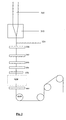
- Fig 1 shows the schematic diagram of the draw tower where the preform is drawn to fiber.
- An optical fiber preform 300 is fed into a drawing furnace 310 for softening by heating.
- An optical fiber 320 is drawn form one end of the softened optical fiber preform 300.
- the drawn optical fiber 320 is passed through a coating unit 340 via a diameter monitor 330, to be coated with a polymer coating by a coating unit 340.
- the optical fiber 320 is preferably sequentially passed through a coating concentricity monitor 350, a coating resin setting unit 360 e.g. UV lamp, and a coating diameter monitor 370.
- the optical fiber 320 is passed through a Fiber Spinning Unit (FSU) 410.
- FSU Fiber Spinning Unit
- the fiber spinning unit comprises of four wheels one servomotor to control the spinning of the wheels. Out of four wheels two are guiding wheels and two are spinning wheels. These two guiding wheels are on the upper side of the unit and they guide the fiber during normal run. According to this invention, the lower pair of wheels are spinning wheels, these wheels directly touch the fiber during draw.
- Fig 2 shows a schematic diagram of a spinning wheels/guiding wheels.
- the diameter of the wheel is of the order of about 80 mm
- the width of the wheel on which the fiber spins is about 12 mm
- a flange is curved out of the wheel as shown in Fig 2.
- the depth and thickness of the flange are about 5.66 mm and about 2.8 mm respectively.
- the gap between the guiding wheels is maintained at about 3 mm. This gap is maintained to prevent the slip of the fiber on the spinning wheels. Further, the distance between the spinning wheels is kept at about 0.3 mm. The height difference between the centers of guiding and spinning wheels is maintained at about 50 mm.
- the compression force is maintained in the range varying from about 0.7 to about 1.2 N. This force can be adjusted in the conventional manner. However, according to this invention it is adjusted with the spring attached to the wheels.
- the clockwise and anticlockwise motion of the spinning wheel is driven by means of a tilting plate 710.
- the tilting plate 710 is a circular plate whose thickness varies along the circumference.
- the tilting plate is supported on a non-moving base 720.
- the spinning wheel is connected to a contact roller 730 with a rod 740.
- the contact roller moves on the circumference of the tilting plate 710.
- the spring force given by the spring 750 provides the flexible movement of the rod about an axis at the contact roller.
- the contact roller 730 moves up and down with respect to the horizontal reference plane XX'. This motion in turn gives an up and down motion to the rod 740.
- the servomotor is coupled with the drive, which receives a feedback from the PLC attached with the system.
- All Process parameters to rotate the wheels like clockwise angle and counter clockwise angle for different ranges of length can be set on user friendly MMI.
- This FSU is mounted on a table. The horizontal and vertical alignment of the system can be done. In the normal run the alignment of the FSU is important, any misalignment may generate vibration in the fiber resulting in wrong reading in the Bubble detector mounted below FSU or bad coating application.
- the fiber then passes through a flaw detector 440.
- the optical fiber 320 after passing through the flaw detector 440 runs through the capstan 450.
- the optical fiber 320 then is passed onto a take up spool with a set of guide rollers.
- the spin rate of the presently disclosed method results in effectively reduced PMD value which is as low as less than about 0.3 ps/ ⁇ km at post cabling stage.
- the spin function of the presently disclosed method also results in draw speed ranging between about 10 to about 23 meters/ sec.
- the spin function in accordance with the present invention has a trapezoidal shape with the following parameters:
- ⁇ K (spin rate) where ⁇ [Fig. 4] is the amplitude of swing motion and K is a constant. This implies that when the spin rate increases the angle of maximum rotation also increases and vice versa.
- the speed of the angular motion of the spinning wheel is dependent on the line speed, swivel length and the spin rate.
- the presently disclosed method for drawing an optical fiber having reducing polarization mode dispersion comprises the steps of :
- the combination of four discrete spin functions repeats after a specific length in the range varying between about 800-1200 meters.
- the cabled fiber PMD achieved has a minimum of about 99.0 % compliance with about 0.3-ps/ ⁇ km.
- the fiber drawing speed varies from about 10 to about 23 meters/sec.
- the coated optical fiber diameter is in the range varying from about 240 to about 250 micron.
- the gap between the two guiding wheels is at least about 0.3 mm.
- the gap between the two spinning wheels is at max about 0.35 mm.
- the difference between gap of spinning wheels and coated fiber diameter is in the range varying from about 30 to about 100 micron for achieving a compression force in the range varying from about 0.7 to about 1.2 N.
- the distance between the centers of the guiding wheels and the spinning wheels is at least about 45 mm.
- the distance between the spinning roller and capstan is less than about 35 cm for efficient damping of vibration of the fiber.
- the single mode optical fiber made in accordance with the presently disclosed method is also provided.
- the single mode optical fiber is used in the optical communication system consisting of a transmitter and receiver.
- the experimental study was carried out in 13 stages with different spin functions to achieve the effectively reduced PMD of the fiber.
- the fiber drawn with different spin functions were cabled.
- the PMD of the cabled fiber was measured and these values were used as feedback to modify the spin function.
- Table 2(a) shows the spin function with which the inventors were able to achieve the best results in the cabled fiber PMD using single spin function.
- Clockwise Counter clockwise Spins per meter 10 10 Spin length 16 16 Swivel length 1 1 Straight length 1 Cabled fiber PMD results.
- the PMD results the percentage compliance to the desired PMD value of about 0.3-ps/ ⁇ km was low, the inventors experimented on a combination of four different spin rates to achieve the effectively reduced PMD of the fiber. These spin rates were repeated in a definite sequence to effectively lower the PMD of the fiber. The inventors merged the best of single spin rate functions.
- the structure of the recipe is designed such that recipe # 1 is continued for the times mentioned in repeat gain and then switch to recipe 2. This process continues till recipe # 4 is completed.
- the complete recipe finishes within a length of about 1000 meters of fiber drawn.
- the above recipe is independent of drawing speed and has shown good compliance with cabled fiber PMD.
- the present invention therefore, provides a fiber spinning method, which uses a combination of four different spin rates, which repeats itself after a length of about 1000 meters. This method ensures about 99.1 % compliance of cabled fiber PMD.
Landscapes
- Chemical & Material Sciences (AREA)
- Engineering & Computer Science (AREA)
- Life Sciences & Earth Sciences (AREA)
- General Life Sciences & Earth Sciences (AREA)
- Geochemistry & Mineralogy (AREA)
- Manufacturing & Machinery (AREA)
- Materials Engineering (AREA)
- Organic Chemistry (AREA)
- Dispersion Chemistry (AREA)
- Optical Fibers, Optical Fiber Cores, And Optical Fiber Bundles (AREA)
- Manufacture, Treatment Of Glass Fibers (AREA)
Applications Claiming Priority (2)
| Application Number | Priority Date | Filing Date | Title |
|---|---|---|---|
| IN38MU2003 | 2003-01-13 | ||
| INMU00382003 | 2003-01-13 |
Publications (3)
| Publication Number | Publication Date |
|---|---|
| EP1439150A2 true EP1439150A2 (de) | 2004-07-21 |
| EP1439150A3 EP1439150A3 (de) | 2004-08-04 |
| EP1439150B1 EP1439150B1 (de) | 2007-02-14 |
Family
ID=32587701
Family Applications (1)
| Application Number | Title | Priority Date | Filing Date |
|---|---|---|---|
| EP04250119A Expired - Lifetime EP1439150B1 (de) | 2003-01-13 | 2004-01-12 | Verfahren zum Herstellen einer tordierten optischen Faser mit verringerter Polarisationsmodendispersion |
Country Status (5)
| Country | Link |
|---|---|
| US (1) | US7310974B2 (de) |
| EP (1) | EP1439150B1 (de) |
| CN (1) | CN1262502C (de) |
| AT (1) | ATE353857T1 (de) |
| DE (1) | DE602004004680T2 (de) |
Cited By (1)
| Publication number | Priority date | Publication date | Assignee | Title |
|---|---|---|---|---|
| WO2006058551A1 (en) * | 2004-12-02 | 2006-06-08 | Prysmian Cavi E Sistemi Energia S.R.L. | Method, system and device for imparting a predetermined rotation to an optical fibre |
Families Citing this family (5)
| Publication number | Priority date | Publication date | Assignee | Title |
|---|---|---|---|---|
| US7317855B2 (en) * | 2004-12-16 | 2008-01-08 | Corning Incorporated | Method of imparting twist to optical fiber |
| US20080285927A1 (en) * | 2006-04-24 | 2008-11-20 | Sterlite Optical Technologies Ltd. | Single Mode Optical Fiber Having Reduced Macrobending and Attenuation Loss and Method for Manufacturing the Same |
| US8443581B2 (en) * | 2008-10-20 | 2013-05-21 | Sumitomo Electric Industries, Ltd. | Method and apparatus for producing optical fiber |
| US20100296155A1 (en) * | 2009-05-19 | 2010-11-25 | Waterford Institute Of Technology | Optical fiber raman amplifier |
| KR20240111613A (ko) | 2023-01-10 | 2024-07-17 | 주식회사 휴비츠 | 광 파이버 광원 폴라라이저 |
Citations (3)
| Publication number | Priority date | Publication date | Assignee | Title |
|---|---|---|---|---|
| US5418881A (en) * | 1992-08-03 | 1995-05-23 | At&T Corp. | Article comprising optical fiber having low polarization mode dispersion, due to permanent spin |
| WO1997026221A1 (en) * | 1996-01-22 | 1997-07-24 | Corning Incorporated | Optical fiberof modulated spin for reduced polarisation mode dispersion as well as process and apparatus for its manufacture |
| WO2002003115A1 (en) * | 2000-07-06 | 2002-01-10 | Pirelli Cavi E Sistemi S.P.A. | Optical fibre with reduced polarization mode dispersion and method for obtaining an optical fibre with reduced polarization mode dispersion |
Family Cites Families (5)
| Publication number | Priority date | Publication date | Assignee | Title |
|---|---|---|---|---|
| US4473273A (en) | 1981-09-04 | 1984-09-25 | Trw Inc. | High bandwidth fiber and method of forming the same by preform rotation during drawing |
| EP0785913B1 (de) * | 1995-08-16 | 2000-05-31 | Plasma Optical Fibre B.V. | Optische faser mit geringer polarisations-moden-dispersion |
| KR20010071612A (ko) * | 1998-06-24 | 2001-07-28 | 지아네시 피에르 지오반니 | 원석으로부터 광섬유를 제조하기 위한 장치 및 방법 |
| JPWO2002063354A1 (ja) * | 2001-01-30 | 2004-06-10 | 住友電気工業株式会社 | 光ファイバの製造方法及び製造装置 |
| US20040107734A1 (en) * | 2002-12-04 | 2004-06-10 | Paresh Kenkare | Systems and methods for fabricating optical fiber preforms |
-
2004
- 2004-01-09 US US10/754,904 patent/US7310974B2/en active Active
- 2004-01-12 AT AT04250119T patent/ATE353857T1/de active
- 2004-01-12 DE DE602004004680T patent/DE602004004680T2/de not_active Expired - Lifetime
- 2004-01-12 EP EP04250119A patent/EP1439150B1/de not_active Expired - Lifetime
- 2004-01-13 CN CNB2004100009017A patent/CN1262502C/zh not_active Expired - Fee Related
Patent Citations (3)
| Publication number | Priority date | Publication date | Assignee | Title |
|---|---|---|---|---|
| US5418881A (en) * | 1992-08-03 | 1995-05-23 | At&T Corp. | Article comprising optical fiber having low polarization mode dispersion, due to permanent spin |
| WO1997026221A1 (en) * | 1996-01-22 | 1997-07-24 | Corning Incorporated | Optical fiberof modulated spin for reduced polarisation mode dispersion as well as process and apparatus for its manufacture |
| WO2002003115A1 (en) * | 2000-07-06 | 2002-01-10 | Pirelli Cavi E Sistemi S.P.A. | Optical fibre with reduced polarization mode dispersion and method for obtaining an optical fibre with reduced polarization mode dispersion |
Cited By (1)
| Publication number | Priority date | Publication date | Assignee | Title |
|---|---|---|---|---|
| WO2006058551A1 (en) * | 2004-12-02 | 2006-06-08 | Prysmian Cavi E Sistemi Energia S.R.L. | Method, system and device for imparting a predetermined rotation to an optical fibre |
Also Published As
| Publication number | Publication date |
|---|---|
| CN1519212A (zh) | 2004-08-11 |
| EP1439150A3 (de) | 2004-08-04 |
| DE602004004680D1 (de) | 2007-03-29 |
| US20040163418A1 (en) | 2004-08-26 |
| DE602004004680T2 (de) | 2007-11-22 |
| CN1262502C (zh) | 2006-07-05 |
| US7310974B2 (en) | 2007-12-25 |
| EP1439150B1 (de) | 2007-02-14 |
| ATE353857T1 (de) | 2007-03-15 |
Similar Documents
| Publication | Publication Date | Title |
|---|---|---|
| US6240748B1 (en) | Frequency and amplitude modulated fiber spins for PMD reduction | |
| JP2981088B2 (ja) | 光ファイバとその製造方法及び光通信システム | |
| CN100434378C (zh) | 低偏振波型色散光纤维及其制造工艺和装置 | |
| US6550282B2 (en) | Method and apparatus for manufacturing an optical fiber from a preform | |
| US6859596B2 (en) | Systems and methods for forming ultra-low PMD optical fiber using amplitude and frequency keyed fiber spin functions | |
| US20040232571A1 (en) | Method for manufacturing low PMD single-mode fiber and optical fiber manufactured by the same | |
| EP1532475B1 (de) | Vorrichtung zum verdrehen einer optischen faser, herstellungsverfahren der optischen faser, und vorrichtung, die diese verwendet | |
| EP1604237B1 (de) | Verdrehte optische faser mit niedriger polarisationsmodendispersion und entsprechendes herstellungsverfahren | |
| US7310974B2 (en) | Method for producing twisted optical fiber with reduced polarization mode dispersion | |
| NZ509043A (en) | Method and apparatus for twisting a coated optical fiber during drawing from a preform | |
| WO2008049375A1 (fr) | Procédé de fabrication d'une fibre optique monomode présentant une faible pmd | |
| US20010046358A1 (en) | Optical fiber, method of making the same, and optical transmission system including the same | |
| US20040011083A1 (en) | Optical fiber drawing system for non-contact control of polarizatiion mode dispersion of optical fiber | |
| EP1116701A1 (de) | Verfahren zur herstellung von optischen fasern | |
| US20050069267A1 (en) | Method of making spun optical fiber with low PMD | |
| US7891216B2 (en) | Method for producing an optical fiber having low polarization mode dispersion | |
| US7383703B2 (en) | Anti-PMD system for optical fibers | |
| US8666213B2 (en) | Method of making multimode optical fibers |
Legal Events
| Date | Code | Title | Description |
|---|---|---|---|
| PUAI | Public reference made under article 153(3) epc to a published international application that has entered the european phase |
Free format text: ORIGINAL CODE: 0009012 |
|
| PUAL | Search report despatched |
Free format text: ORIGINAL CODE: 0009013 |
|
| AK | Designated contracting states |
Kind code of ref document: A2 Designated state(s): AT BE BG CH CY CZ DE DK EE ES FI FR GB GR HU IE IT LI LU MC NL PT RO SE SI SK TR |
|
| AX | Request for extension of the european patent |
Extension state: AL LT LV MK |
|
| AK | Designated contracting states |
Kind code of ref document: A3 Designated state(s): AT BE BG CH CY CZ DE DK EE ES FI FR GB GR HU IE IT LI LU MC NL PT RO SE SI SK TR |
|
| AX | Request for extension of the european patent |
Extension state: AL LT LV MK |
|
| 17P | Request for examination filed |
Effective date: 20050204 |
|
| 17Q | First examination report despatched |
Effective date: 20050225 |
|
| AKX | Designation fees paid |
Designated state(s): AT BE BG CH CY CZ DE DK EE ES FI FR GB GR HU IE IT LI LU MC NL PT RO SE SI SK TR |
|
| AXX | Extension fees paid |
Extension state: MK Payment date: 20050204 Extension state: LT Payment date: 20050204 Extension state: AL Payment date: 20050204 Extension state: LV Payment date: 20050204 |
|
| GRAP | Despatch of communication of intention to grant a patent |
Free format text: ORIGINAL CODE: EPIDOSNIGR1 |
|
| RIC1 | Information provided on ipc code assigned before grant |
Ipc: C03B 37/027 20060101AFI20060919BHEP Ipc: C03B 37/03 20060101ALI20060919BHEP |
|
| GRAS | Grant fee paid |
Free format text: ORIGINAL CODE: EPIDOSNIGR3 |
|
| GRAA | (expected) grant |
Free format text: ORIGINAL CODE: 0009210 |
|
| AK | Designated contracting states |
Kind code of ref document: B1 Designated state(s): AT BE BG CH CY CZ DE DK EE ES FI FR GB GR HU IE IT LI LU MC NL PT RO SE SI SK TR |
|
| AX | Request for extension of the european patent |
Extension state: AL LT LV MK |
|
| PG25 | Lapsed in a contracting state [announced via postgrant information from national office to epo] |
Ref country code: BE Free format text: LAPSE BECAUSE OF FAILURE TO SUBMIT A TRANSLATION OF THE DESCRIPTION OR TO PAY THE FEE WITHIN THE PRESCRIBED TIME-LIMIT Effective date: 20070214 Ref country code: LI Free format text: LAPSE BECAUSE OF FAILURE TO SUBMIT A TRANSLATION OF THE DESCRIPTION OR TO PAY THE FEE WITHIN THE PRESCRIBED TIME-LIMIT Effective date: 20070214 Ref country code: FI Free format text: LAPSE BECAUSE OF FAILURE TO SUBMIT A TRANSLATION OF THE DESCRIPTION OR TO PAY THE FEE WITHIN THE PRESCRIBED TIME-LIMIT Effective date: 20070214 Ref country code: CH Free format text: LAPSE BECAUSE OF FAILURE TO SUBMIT A TRANSLATION OF THE DESCRIPTION OR TO PAY THE FEE WITHIN THE PRESCRIBED TIME-LIMIT Effective date: 20070214 Ref country code: SI Free format text: LAPSE BECAUSE OF FAILURE TO SUBMIT A TRANSLATION OF THE DESCRIPTION OR TO PAY THE FEE WITHIN THE PRESCRIBED TIME-LIMIT Effective date: 20070214 Ref country code: NL Free format text: LAPSE BECAUSE OF FAILURE TO SUBMIT A TRANSLATION OF THE DESCRIPTION OR TO PAY THE FEE WITHIN THE PRESCRIBED TIME-LIMIT Effective date: 20070214 Ref country code: DK Free format text: LAPSE BECAUSE OF FAILURE TO SUBMIT A TRANSLATION OF THE DESCRIPTION OR TO PAY THE FEE WITHIN THE PRESCRIBED TIME-LIMIT Effective date: 20070214 |
|
| REG | Reference to a national code |
Ref country code: GB Ref legal event code: FG4D |
|
| REG | Reference to a national code |
Ref country code: CH Ref legal event code: EP |
|
| REF | Corresponds to: |
Ref document number: 602004004680 Country of ref document: DE Date of ref document: 20070329 Kind code of ref document: P |
|
| REG | Reference to a national code |
Ref country code: IE Ref legal event code: FG4D |
|
| PG25 | Lapsed in a contracting state [announced via postgrant information from national office to epo] |
Ref country code: SE Free format text: LAPSE BECAUSE OF FAILURE TO SUBMIT A TRANSLATION OF THE DESCRIPTION OR TO PAY THE FEE WITHIN THE PRESCRIBED TIME-LIMIT Effective date: 20070514 |
|
| PG25 | Lapsed in a contracting state [announced via postgrant information from national office to epo] |
Ref country code: BG Free format text: LAPSE BECAUSE OF EXPIRATION OF PROTECTION Effective date: 20070515 |
|
| PG25 | Lapsed in a contracting state [announced via postgrant information from national office to epo] |
Ref country code: ES Free format text: LAPSE BECAUSE OF FAILURE TO SUBMIT A TRANSLATION OF THE DESCRIPTION OR TO PAY THE FEE WITHIN THE PRESCRIBED TIME-LIMIT Effective date: 20070525 |
|
| PG25 | Lapsed in a contracting state [announced via postgrant information from national office to epo] |
Ref country code: PT Free format text: LAPSE BECAUSE OF FAILURE TO SUBMIT A TRANSLATION OF THE DESCRIPTION OR TO PAY THE FEE WITHIN THE PRESCRIBED TIME-LIMIT Effective date: 20070716 |
|
| LTIE | Lt: invalidation of european patent or patent extension |
Effective date: 20070214 |
|
| NLV1 | Nl: lapsed or annulled due to failure to fulfill the requirements of art. 29p and 29m of the patents act | ||
| REG | Reference to a national code |
Ref country code: CH Ref legal event code: PL |
|
| EN | Fr: translation not filed | ||
| PG25 | Lapsed in a contracting state [announced via postgrant information from national office to epo] |
Ref country code: SK Free format text: LAPSE BECAUSE OF FAILURE TO SUBMIT A TRANSLATION OF THE DESCRIPTION OR TO PAY THE FEE WITHIN THE PRESCRIBED TIME-LIMIT Effective date: 20070214 |
|
| PLBE | No opposition filed within time limit |
Free format text: ORIGINAL CODE: 0009261 |
|
| STAA | Information on the status of an ep patent application or granted ep patent |
Free format text: STATUS: NO OPPOSITION FILED WITHIN TIME LIMIT |
|
| PG25 | Lapsed in a contracting state [announced via postgrant information from national office to epo] |
Ref country code: CZ Free format text: LAPSE BECAUSE OF FAILURE TO SUBMIT A TRANSLATION OF THE DESCRIPTION OR TO PAY THE FEE WITHIN THE PRESCRIBED TIME-LIMIT Effective date: 20070214 Ref country code: RO Free format text: LAPSE BECAUSE OF FAILURE TO SUBMIT A TRANSLATION OF THE DESCRIPTION OR TO PAY THE FEE WITHIN THE PRESCRIBED TIME-LIMIT Effective date: 20070214 |
|
| 26N | No opposition filed |
Effective date: 20071115 |
|
| PG25 | Lapsed in a contracting state [announced via postgrant information from national office to epo] |
Ref country code: IT Free format text: LAPSE BECAUSE OF FAILURE TO SUBMIT A TRANSLATION OF THE DESCRIPTION OR TO PAY THE FEE WITHIN THE PRESCRIBED TIME-LIMIT Effective date: 20070214 Ref country code: GR Free format text: LAPSE BECAUSE OF FAILURE TO SUBMIT A TRANSLATION OF THE DESCRIPTION OR TO PAY THE FEE WITHIN THE PRESCRIBED TIME-LIMIT Effective date: 20070515 Ref country code: FR Free format text: LAPSE BECAUSE OF FAILURE TO SUBMIT A TRANSLATION OF THE DESCRIPTION OR TO PAY THE FEE WITHIN THE PRESCRIBED TIME-LIMIT Effective date: 20071005 |
|
| PG25 | Lapsed in a contracting state [announced via postgrant information from national office to epo] |
Ref country code: MC Free format text: LAPSE BECAUSE OF NON-PAYMENT OF DUE FEES Effective date: 20080131 |
|
| PG25 | Lapsed in a contracting state [announced via postgrant information from national office to epo] |
Ref country code: FR Free format text: LAPSE BECAUSE OF FAILURE TO SUBMIT A TRANSLATION OF THE DESCRIPTION OR TO PAY THE FEE WITHIN THE PRESCRIBED TIME-LIMIT Effective date: 20070214 |
|
| PG25 | Lapsed in a contracting state [announced via postgrant information from national office to epo] |
Ref country code: IE Free format text: LAPSE BECAUSE OF NON-PAYMENT OF DUE FEES Effective date: 20080114 Ref country code: EE Free format text: LAPSE BECAUSE OF FAILURE TO SUBMIT A TRANSLATION OF THE DESCRIPTION OR TO PAY THE FEE WITHIN THE PRESCRIBED TIME-LIMIT Effective date: 20070214 |
|
| PG25 | Lapsed in a contracting state [announced via postgrant information from national office to epo] |
Ref country code: CY Free format text: LAPSE BECAUSE OF FAILURE TO SUBMIT A TRANSLATION OF THE DESCRIPTION OR TO PAY THE FEE WITHIN THE PRESCRIBED TIME-LIMIT Effective date: 20070214 |
|
| PG25 | Lapsed in a contracting state [announced via postgrant information from national office to epo] |
Ref country code: HU Free format text: LAPSE BECAUSE OF FAILURE TO SUBMIT A TRANSLATION OF THE DESCRIPTION OR TO PAY THE FEE WITHIN THE PRESCRIBED TIME-LIMIT Effective date: 20070815 Ref country code: LU Free format text: LAPSE BECAUSE OF NON-PAYMENT OF DUE FEES Effective date: 20080112 |
|
| PG25 | Lapsed in a contracting state [announced via postgrant information from national office to epo] |
Ref country code: TR Free format text: LAPSE BECAUSE OF FAILURE TO SUBMIT A TRANSLATION OF THE DESCRIPTION OR TO PAY THE FEE WITHIN THE PRESCRIBED TIME-LIMIT Effective date: 20070214 |
|
| REG | Reference to a national code |
Ref country code: DE Ref legal event code: R119 Ref document number: 602004004680 Country of ref document: DE |
|
| REG | Reference to a national code |
Ref country code: AT Ref legal event code: MM01 Ref document number: 353857 Country of ref document: AT Kind code of ref document: T Effective date: 20180112 |
|
| GBPC | Gb: european patent ceased through non-payment of renewal fee |
Effective date: 20180112 |
|
| REG | Reference to a national code |
Ref country code: DE Ref legal event code: R073 Ref document number: 602004004680 Country of ref document: DE |
|
| PG25 | Lapsed in a contracting state [announced via postgrant information from national office to epo] |
Ref country code: DE Free format text: LAPSE BECAUSE OF NON-PAYMENT OF DUE FEES Effective date: 20180801 |
|
| REG | Reference to a national code |
Ref country code: DE Ref legal event code: R074 Ref document number: 602004004680 Country of ref document: DE |
|
| REG | Reference to a national code |
Ref country code: DE Ref legal event code: R074 Ref document number: 602004004680 Country of ref document: DE |
|
| REG | Reference to a national code |
Ref country code: GB Ref legal event code: S28 Free format text: APPLICATION FILED |
|
| PG25 | Lapsed in a contracting state [announced via postgrant information from national office to epo] |
Ref country code: AT Free format text: LAPSE BECAUSE OF NON-PAYMENT OF DUE FEES Effective date: 20180112 Ref country code: GB Free format text: LAPSE BECAUSE OF NON-PAYMENT OF DUE FEES Effective date: 20180112 |
|
| REG | Reference to a national code |
Ref country code: GB Ref legal event code: S28 Free format text: RESTORATION ALLOWED Effective date: 20190109 |
|
| PG25 | Lapsed in a contracting state [announced via postgrant information from national office to epo] |
Ref country code: DE Free format text: LAPSE BECAUSE OF NON-PAYMENT OF DUE FEES Effective date: 20180801 |
|
| PGRI | Patent reinstated in contracting state [announced from national office to epo] |
Ref country code: DE Effective date: 20181113 |
|
| REG | Reference to a national code |
Ref country code: AT Ref legal event code: NFJG Ref document number: 353857 Country of ref document: AT Kind code of ref document: T Effective date: 20190320 |
|
| PGFP | Annual fee paid to national office [announced via postgrant information from national office to epo] |
Ref country code: AT Payment date: 20190522 Year of fee payment: 16 |
|
| REG | Reference to a national code |
Ref country code: AT Ref legal event code: MM01 Ref document number: 353857 Country of ref document: AT Kind code of ref document: T Effective date: 20200112 |
|
| PG25 | Lapsed in a contracting state [announced via postgrant information from national office to epo] |
Ref country code: AT Free format text: LAPSE BECAUSE OF NON-PAYMENT OF DUE FEES Effective date: 20200112 |
|
| PGFP | Annual fee paid to national office [announced via postgrant information from national office to epo] |
Ref country code: GB Payment date: 20230109 Year of fee payment: 20 Ref country code: DE Payment date: 20230224 Year of fee payment: 20 |
|
| REG | Reference to a national code |
Ref country code: DE Ref legal event code: R071 Ref document number: 602004004680 Country of ref document: DE |
|
| REG | Reference to a national code |
Ref country code: GB Ref legal event code: PE20 Expiry date: 20240111 |
|
| PG25 | Lapsed in a contracting state [announced via postgrant information from national office to epo] |
Ref country code: GB Free format text: LAPSE BECAUSE OF EXPIRATION OF PROTECTION Effective date: 20240111 |