EP1439135A1 - Chemical resistant sheet lined tank - Google Patents
Chemical resistant sheet lined tank Download PDFInfo
- Publication number
- EP1439135A1 EP1439135A1 EP02762801A EP02762801A EP1439135A1 EP 1439135 A1 EP1439135 A1 EP 1439135A1 EP 02762801 A EP02762801 A EP 02762801A EP 02762801 A EP02762801 A EP 02762801A EP 1439135 A1 EP1439135 A1 EP 1439135A1
- Authority
- EP
- European Patent Office
- Prior art keywords
- tank
- sheet
- chemical
- outer sheet
- metallic
- Prior art date
- Legal status (The legal status is an assumption and is not a legal conclusion. Google has not performed a legal analysis and makes no representation as to the accuracy of the status listed.)
- Withdrawn
Links
Images


Classifications
-
- B—PERFORMING OPERATIONS; TRANSPORTING
- B65—CONVEYING; PACKING; STORING; HANDLING THIN OR FILAMENTARY MATERIAL
- B65D—CONTAINERS FOR STORAGE OR TRANSPORT OF ARTICLES OR MATERIALS, e.g. BAGS, BARRELS, BOTTLES, BOXES, CANS, CARTONS, CRATES, DRUMS, JARS, TANKS, HOPPERS, FORWARDING CONTAINERS; ACCESSORIES, CLOSURES, OR FITTINGS THEREFOR; PACKAGING ELEMENTS; PACKAGES
- B65D90/00—Component parts, details or accessories for large containers
- B65D90/02—Wall construction
- B65D90/04—Linings
-
- B—PERFORMING OPERATIONS; TRANSPORTING
- B65—CONVEYING; PACKING; STORING; HANDLING THIN OR FILAMENTARY MATERIAL
- B65D—CONTAINERS FOR STORAGE OR TRANSPORT OF ARTICLES OR MATERIALS, e.g. BAGS, BARRELS, BOTTLES, BOXES, CANS, CARTONS, CRATES, DRUMS, JARS, TANKS, HOPPERS, FORWARDING CONTAINERS; ACCESSORIES, CLOSURES, OR FITTINGS THEREFOR; PACKAGING ELEMENTS; PACKAGES
- B65D90/00—Component parts, details or accessories for large containers
- B65D90/02—Wall construction
- B65D90/04—Linings
- B65D90/041—Rigid liners fixed to the container
- B65D90/044—Rigid liners fixed to the container fixed or supported over substantially the whole interface
-
- B—PERFORMING OPERATIONS; TRANSPORTING
- B32—LAYERED PRODUCTS
- B32B—LAYERED PRODUCTS, i.e. PRODUCTS BUILT-UP OF STRATA OF FLAT OR NON-FLAT, e.g. CELLULAR OR HONEYCOMB, FORM
- B32B1/00—Layered products having a non-planar shape
-
- B—PERFORMING OPERATIONS; TRANSPORTING
- B32—LAYERED PRODUCTS
- B32B—LAYERED PRODUCTS, i.e. PRODUCTS BUILT-UP OF STRATA OF FLAT OR NON-FLAT, e.g. CELLULAR OR HONEYCOMB, FORM
- B32B15/00—Layered products comprising a layer of metal
- B32B15/04—Layered products comprising a layer of metal comprising metal as the main or only constituent of a layer, which is next to another layer of the same or of a different material
-
- B—PERFORMING OPERATIONS; TRANSPORTING
- B32—LAYERED PRODUCTS
- B32B—LAYERED PRODUCTS, i.e. PRODUCTS BUILT-UP OF STRATA OF FLAT OR NON-FLAT, e.g. CELLULAR OR HONEYCOMB, FORM
- B32B15/00—Layered products comprising a layer of metal
- B32B15/04—Layered products comprising a layer of metal comprising metal as the main or only constituent of a layer, which is next to another layer of the same or of a different material
- B32B15/08—Layered products comprising a layer of metal comprising metal as the main or only constituent of a layer, which is next to another layer of the same or of a different material of synthetic resin
-
- B—PERFORMING OPERATIONS; TRANSPORTING
- B32—LAYERED PRODUCTS
- B32B—LAYERED PRODUCTS, i.e. PRODUCTS BUILT-UP OF STRATA OF FLAT OR NON-FLAT, e.g. CELLULAR OR HONEYCOMB, FORM
- B32B3/00—Layered products comprising a layer with external or internal discontinuities or unevennesses, or a layer of non-planar shape; Layered products comprising a layer having particular features of form
- B32B3/10—Layered products comprising a layer with external or internal discontinuities or unevennesses, or a layer of non-planar shape; Layered products comprising a layer having particular features of form characterised by a discontinuous layer, i.e. formed of separate pieces of material
- B32B3/18—Layered products comprising a layer with external or internal discontinuities or unevennesses, or a layer of non-planar shape; Layered products comprising a layer having particular features of form characterised by a discontinuous layer, i.e. formed of separate pieces of material characterised by an internal layer formed of separate pieces of material which are juxtaposed side-by-side
- B32B3/22—Layered products comprising a layer with external or internal discontinuities or unevennesses, or a layer of non-planar shape; Layered products comprising a layer having particular features of form characterised by a discontinuous layer, i.e. formed of separate pieces of material characterised by an internal layer formed of separate pieces of material which are juxtaposed side-by-side of spaced pieces
-
- B—PERFORMING OPERATIONS; TRANSPORTING
- B65—CONVEYING; PACKING; STORING; HANDLING THIN OR FILAMENTARY MATERIAL
- B65D—CONTAINERS FOR STORAGE OR TRANSPORT OF ARTICLES OR MATERIALS, e.g. BAGS, BARRELS, BOTTLES, BOXES, CANS, CARTONS, CRATES, DRUMS, JARS, TANKS, HOPPERS, FORWARDING CONTAINERS; ACCESSORIES, CLOSURES, OR FITTINGS THEREFOR; PACKAGING ELEMENTS; PACKAGES
- B65D90/00—Component parts, details or accessories for large containers
- B65D90/02—Wall construction
- B65D90/04—Linings
- B65D90/046—Flexible liners, e.g. loosely positioned in the container
-
- B—PERFORMING OPERATIONS; TRANSPORTING
- B65—CONVEYING; PACKING; STORING; HANDLING THIN OR FILAMENTARY MATERIAL
- B65D—CONTAINERS FOR STORAGE OR TRANSPORT OF ARTICLES OR MATERIALS, e.g. BAGS, BARRELS, BOTTLES, BOXES, CANS, CARTONS, CRATES, DRUMS, JARS, TANKS, HOPPERS, FORWARDING CONTAINERS; ACCESSORIES, CLOSURES, OR FITTINGS THEREFOR; PACKAGING ELEMENTS; PACKAGES
- B65D90/00—Component parts, details or accessories for large containers
- B65D90/22—Safety features
- B65D90/24—Spillage-retaining means, e.g. recovery ponds
Definitions
- the present invention relates to tanks lined with chemical-resistant lining sheets, and in particular to tanks lined with chemical-resistant lining sheets for use in storing or reacting various kinds of chemicals (e.g., chemical liquids), especially chemicals having high infiltratability or permeability.
- chemicals e.g., chemical liquids
- tanks for the use in handling corrosive liquids such as various chemicals or solvents are lined at their whole interior walls with lining sheets of chemical-resistant materials such as polyvinyl chloride, rubber, polytetrafluoroethylene (or PTFE), i.e., one of fluororesins, or the like so as to prevent the corrosion of the interior walls of the tanks due to such chemical liquids, or the contamination of the chemical liquids due to such corrosion, or the leakage of the chemical liquids from the tanks due to the damage of the tanks caused by such corrosion.
- the chemical-storage tanks lined with the sheets of fluororesins are widely used, the fluororesins having far more excellent properties than other synthetic resins, particularly in view of heat resistance, chemical resistance, non-stickness, purity, etc.
- Japanese Laid-Open Patent Publication No. 8-80996 proposes a chemical-storage tank for semiconductors which is lined with two layers of lining sheets: that is, the tank is lined with a fluororesin sheet which is to be contact with a chemical liquid, and the tank is further lined with a general resin lining material other than the fluororesin, at the reverse side of the fluororesin sheet.
- the chemical resistance of the general resin lining material used as the intermediate layer is lower than that of the fluororesin lining sheet material.
- the permeating chemical liquid is always kept in contact with the intermediate layer, i.e., the general resin lining material which dissolves more easily than the fluororesin lining sheet, and consequently, the chemical liquid in the tank permeates the two layers of the lining sheets and corrodes the metallic surface of the tank. As a result, the chemical liquid is contaminated by the metal, and the metallic tank body is damaged.
- the chemical liquid which has leaked through the first fluororesin lining sheet is always in contact with the second fluororesin lining sheet, which results in the permeation of the chemical liquid through the two lining sheets, followed by the corrosion of the metallic surface of the tank.
- the present invention is developed to overcome the foregoing problems which the prior art confronts, and it is therefore an object of the present invention to provide a chemical-storage tank, which does not suffer from the corrosion of the metallic body composing the outer walls of the tank, even if metal-corrosive chemicals (e.g., chemical liquids) are stored.
- metal-corrosive chemicals e.g., chemical liquids
- Another object of the present invention is to provide a tank with which the chemical in the tank can be protected from metal contamination, and the damage of the tank body can be prevented, even if the chemicals stored in the tank are chemicals that can permeate the lining sheet having no defect, depending on the type of the chemicals stored or the working conditions of the tank, for example, chemicals having high permeability to corrode metals.
- a tank lined with chemical-resistant lining sheet at the interior surface of its metallic tank body characterized in that the tank comprises:
- the tank is provided with a suction mechanism which causes the chemical leaking from the tank through the inner sheet to be discharged through the space kept by the spacer, so as to efficiently discharge the leaking chemical by permeation.
- the spacers are in the shape of a cylinder, bar or sphere, and are so disposed as to make it possible to discharge the chemical, which was leaking from the tank through the inner sheet by permeation.
- the tank is lined with two chemical-resistant lining sheets at the interior surface of its metallic tank body, and a space is kept between the inner sheet and the outer sheet. Thanks to this, the metallic tank body can be protected by the outer sheet, even when the chemical leaks trough the inner sheet because the chemical stored in the tank has high permeability to permeate the inner sheet even if the inner sheet itself has no defect such as pinholes. Further, the metallic tank body can be protected from the corrosion due to the leaking chemical, since the space between the inner sheet and the outer sheet is communicated with the outside of the tank, thereby to prevent the leaking chemical from remaining in the space and to discharge the same to the outside of the tank.
- the number of the opportunities where the chemical leaking through the inner sheet comes into contact with the outer sheet can be decreased, so that the deterioration of the outer sheet can be retarded.
- the corrosion of the metallic tank body due to the leaking chemical and the metal contamination of the chemical in the tank along with such corrosion can be prevented.
- the spacers make it possible to hold the space (or clearance) between the outer sheet and the inner sheet against the pressure of the chemical which is stored in the tank, so that the outer sheet does not come into direct contact with the inner sheet. Therefore, even if the chemical in the tank which has high permeability to corrode metals leaks through the inner sheet, the chemical immediately flows down in the above space and exits from the tank, and thus never subsequently permeates the outer sheet. As a result, the corrosion of the metallic tank body can be prevented.
- a chemical-storage tank capable of protecting its metallic tank body from corrosion due to metal-corrosive chemicals. Further, there is provided a tank suitably used to store chemicals which permeate the lining sheet even though the sheet itself has no defect, depending on the type of the chemicals stored or the working conditions of the tank, for example, chemicals having high permeability to corrode metals. Thus, the chemical in the tank can be protected from metal contamination, and the damage of the tank body can be prevented.
- the tank lined with a chemical-resistant lining sheet according to the present invention (hereinafter simply referred to as "tank”) comprises a tank body and a lid for sealing one of the end portions of the tank body (or a bottom for sealing the other end portion thereof).
- Fig. 1 shows one embodiment of the present invention, illustrating the longitudinal sectional view of the cylindrical body of the tank lined with the chemical-resistant lining sheet.
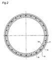
- Fig. 2 shows the cross-sectional view of the tank body shown in Fig. 1, taken along the line X-X.
- Fig. 3 shows the longitudinal sectional view of the lid (or the bottom) to be combined with the tank body shown in Fig. 1.
- the tank body can be joined and connected to another tank body with the openings 6 of the tank bodies confronted to each other.
- the tank body 2 shown in Figs. 1 and 2 comprises a metallic cylindrical body 10 and a two-layer lining consisting of two chemical-resistant sheets with which the metallic cylindrical body 10 is lined.
- This two-layer lining structure comprises an outer sheet 12 which is applied to the interior surface 2a of the metallic cylindrical body 10, an inner sheet 14 which is laid inside the outer sheet 12, and spacers 16 which are disposed between the outer sheet 12 and the inner sheet 14 so as to keep a predetermined distance therebetween, and which hold a space 17 communicating with the outside of the tank body 2.
- the outer sheet 12 is applied to the interior surface 2a of the metallic cylindrical body 10, and the inner sheet 14 is laid inside the outer sheet 12 with the spacers 16 sandwiched therebetween.
- materials for the outer sheet 12 and the inner sheet 14 fluororesins can be used.
- Typical examples of the materials for the outer sheet 12 and the inner sheet 14 include PTFE (polytetrafluoroethylene resins) and PFA (tetrafluoroethylene-perfluoroalkylvinylether copolymer resins).
- PTFE polytetrafluoroethylene resins
- PFA tetrafluoroethylene-perfluoroalkylvinylether copolymer resins
- the outer sheet 12 and the inner sheet 14 there can be used not only PTFE sheets and PFA sheets, but also the surface-treated sheets of PTFE or PFA (particularly at their one side surfaces), such as the sheets over which glass cloth is heat-fused, the sheets which are surface-roughened with a metallic sodium solution so as to improve the adhesive nature, the sheets over which carbon cloth is heat-fused, and the like.
- the outer sheet 12 and the inner sheet 14 may be formed from the same material or different materials. Otherwise, one sheet may be formed from a plurality of different materials.
- the thickness of the outer sheet 12 there is no particular limit in selection of the thickness of the outer sheet 12, since such thickness changes depending on the end use or the application scale of the tank, the kind of a chemical to be stored therein, etc.
- the thickness of the outer sheet is 1 to 6 mm, preferably 2 to 4 mm.
- the thickness of the inner sheet 14 there is no particular limit in selection of the thickness of the inner sheet 14, and for example it is 2 to 6 mm, preferably 2 to 4 mm.
- the spacer 16 there is no particular limit in selection of the shape or material of the spacer 16, as far as the spacer 16 can keep the space 17 between the outer sheet 12 and the inner sheet 14, and can withstand the actions of the chemical stored in the tank.
- the spacer 16 may be formed from the same material as that of the outer sheet 12 and the inner sheet 14, i.e., fluororesins, preferably PTFE or PFA.
- spacer 16 formed from fluororesin is not easily dissolved by the chemical liquid which permeates the inner sheet 14 from the interior of the tank and leaks to the reverse side 14b of the inner sheet 14. Further, since the spacer 16 is disposed between the outer sheet 12 and the inner sheet 14, the space 17 can be kept therebetween under the pressure of the chemical stored in the tank.
- the insertion of the spacer 16 is effective to prevent the direct contact between the outer sheet 12 and the inner sheet 14 so that the chemical liquid permeating the inner sheet 14 can flow down through the space 17 and exit.
- the metallic cylindrical body 10 since the metallic cylindrical body 10 is covered with the outer sheet 12, the metallic cylindrical body 10 can be protected from corrosion with the leaking chemical liquid.
- the spacer 16 is welded or bonded with adhesive between the outer sheet 12 and the inner sheet 14. In this case, it is sufficient for the spacer 16 to be fixed at least on the outer sheet 12, or otherwise, the spacer 16 may be fixed on both of the outer sheet 12 and the inner sheet 14.
- the shape of the spacer 16 there is no particular limit in selection of the shape of the spacer 16, and it may be in the shape of, for example, a cylinder (see Fig. 2), bar (round or prismatic section), sphere, net or the like.
- the spacer 16 is disposed, such that the chemical liquid permeating into the space 17 can flow down to outside without being stopped by the spacer 16.
- a plurality of such spacers 16 may be vertically disposed in parallel with each other at predetermined intervals along the longitudinal direction of the tank (see Fig. 2), or may be horizontally disposed in parallel with each other along the radial direction of the tank (the direction orthogonal to the longitudinal direction of the tank) (not shown).
- each spacer 16 may have chasms, so as to allow the chemical liquid to flow therethrough down to outside (not shown).
- the tank body 2 is supported with its longitudinal direction (or its axial direction) aligned vertically to the ground, it is preferable that the relatively long spacers 16 are vertically disposed in parallel to one another at predetermined intervals along the longitudinal direction of the tank body 2 as shown in Fig. 2, so as to allow the chemical liquid or the like to flow down, so that the down-flowing of the chemical liquid or the like can becomes smooth.
- such relatively long and cylindrical spacers 16 can be disposed at intervals of 10 to 100 mm as shown in Fig. 2.
- the length of the spacers 16 depends on the height of the metallic tank body, and the outer diameter of the cylindrical shape is 3 mm and inner diameter of the cylindrical shape is 1 mm, for example.
- the number of such spacers 16 to be disposed at predetermined intervals are appropriately selected in. accordance with the size of a tank to be lined with a chemical-resistant lining sheet.
- the selected number of spherical spacers 16 are disposed so that a space 19 large enough to allow the chemical leaking through the inner sheet 14 to be discharged from the tank can be ensured at the end portion of the tank body 2, and so that substantially no unevenness is caused on the surface of the inner sheet 14.
- the spherical spacers 16 are disposed one by one at substantially regular intervals within the space 17 so as not to allow the adjacent spacers 16 to contact with each other, while the space between the inner sheet 14 and the outer sheet 12 is being kept at such a distance that corresponds to one or more spacers, preferably one spacer.
- the shape of the spacers 16 and the way of disposing them can be selected so that the space 17 can be ensured, which is enough to discharge the chemical leaking through the inner sheet 14.
- air-passing rings 22, 22 which allow the space 17 to communicate with outside of the tank are provided at the upper end portion and the lower end portion of the metallic cylindrical body 10.
- the air-passing ring 22 at the lower end portion of the tank is used to discharge the chemical, which leaks through the inner sheet 14 to the spacer side, to the outside of the tank.
- a suction mechanism (not shown) which forcedly discharges the leaking chemical to the outside of the tank.
- an air-passing ring which is made of stainless steel or other metal alloy and of which surface is coated with the same material as that for the outer sheet 12 and the inner sheet 14, preferably PTFE, or an air-passing ring which is made of PTFE mixed with a filler (selected in accordance with type of a chemical to be stored).
- PTFE PTFE
- an air-passing ring made of PTFE mixed with a filler in view of creep resistance, it is preferable to use an air-passing ring made of PTFE mixed with a filler.
- the space 17 is so formed as to discharge the chemical leaking to the outside of the tank, when there happens the leaking of the chemical stored in the tank trough the inner sheet, even though the inner sheet 14 itself has no pinhole or crack.
- the suction mechanism forcedly discharges the air in the space 17 to thereby quickly discharge the chemical leaking through the inner sheet 14, to the outside of the tank.
- the lid (or the bottom) 4 for closing the tank body 2 with two layers of chemical-resistant sheets, like as the tank body 2, as shown in Fig. 3.
- the lid (or the bottom) is formed of the same metal material as that for the metallic cylindrical body 10 of the tank body 2, and is lined at its interior surface with a first fluororesin sheet as an outer sheet 12, and further with a second fluororesin sheet as an inner sheet 14, with spacers 16 sandwiched therebetween.
- the tank provided with the lining structure shown in Figs. 1 to 3 may be produced as follows.
- the outer sheet 12 can be applied on the interior wall of the metallic cylindrical body 10 according to a conventional method. For example, a plurality of sheet materials are joined in advance at outside of the tank so as to conform the interior surface configuration of the metallic cylindrical body 10, and the resultant outer sheet 12 is taken into the tank and laid on the intended position on the interior wall of the tank and bonded thereto with adhesive. Otherwise, the sheet materials are successively joined to one another by welding or bonding within the metallic cylindrical body 10, and simultaneously, are bonded to the interior surface 2a of the metallic cylindrical body 10 (on-the-spot application).
- a PFA bar or the like can be used for welding, and rubber type or epoxy type adhesive can be used as the adhesive.
- the lining methods are classified into the “adhesion lining” method in which sheets are secured on a tank body with adhesive, and the “loose lining” method in which a tank body is lined with sheets without adhesive.
- the outer sheet 12 is applied to the interior surface of the metallic cylindrical body by the "loose lining” method, the outer sheet 12 is sucked onto the interior surface of the metallic cylindrical body 10 through vents 20 formed thereon so as to attach the outer sheet 12 to the metallic cylindrical body 10.
- the spacers 16 are set at predetermined intervals.
- the spacers 16 are so disposed that the chemical leaking from the inside of the tank through the inner sheet 14 can flow down and exit to the outside of the tank.
- the cylindrical spacers 16 are disposed at predetermined intervals along the longitudinal direction of the metallic cylindrical body 10, which is supported upright.
- the spacers 16 may be previously bonded on the surface of the outer sheet 12 by welding or using adhesive at the outside of the tank, or otherwise, the spacers 16 may be set on the surface 12a at the chemical side of the outer sheet 12 in the same manner as above, after the outer sheet 12 has been applied to the interior surface 2a of the metallic cylindrical body 10.
- the application of the outer sheet 12 and the spacers 16 onto the interior surface of the metallic cylindrical body 10 can be done within the tank. That is, a plurality of "partial sheet” in each of which the spacers 16 are bonded on the outer sheet 12 are previously prepared, and then, such the "partial sheets” are carried into the metallic cylindrical body 10. Then, workers on-the-spot apply the "partial sheets” on the interior surface of the metallic cylindrical body 10 within the metallic cylindrical body 10. Specifically, each of the "partial sheets” is bonded onto the interior surface of the metallic cylindrical body 10 at its outer sheet 12, and simultaneously is joined to other "partial sheet” at their end portions.
- the inner sheet 14 is then applied on the spacers 16.
- the inner sheet 14 can be laid with a predetermined space away from the outer sheet 12, before the spacers 16 are bonded onto the outer sheet 12.
- the outer sheet 12 and the inner sheet 14 can be so applied as shown in Fig. 1, wherein both the sheets are applied not only on the side wall 2a at the chemical side of the tank body 2 (or the metallic cylindrical body 10), but also on the upper flange 24a and the lower flange 24b of the tank body 2.
- the outer sheet 12 and the inner sheet 14 are stretched so as to extend along the shapes of the flanges 24 of the metallic cylindrical body 10, respectively, in order to protect the surfaces of the flanges 24 from corrosion and pollution due to the chemical or the like.
- Examples of the chemicals to be stored in the tank of the present invention include gases such as a hydrogen chloride gas, chlorine gas, etc., aqueous solutions thereof and mixtures thereof.
- the tank of the present invention can be used as a distillation tank which is intended for producing a hydrogen chloride gas by distilling hydrochloric acid (or an aqueous solution of hydrogen chloride) of high temperature (for example, 100°C or higher), or as an absorption tank which is intended for causing water to absorb a hydrogen chloride gas (which may contain chlorine) of high temperature (for example, 100°C or higher) so as to obtain hydrochloric acid, and simultaneously storing the resultant hydrochloric acid.
- a distillation tank which is intended for producing a hydrogen chloride gas by distilling hydrochloric acid (or an aqueous solution of hydrogen chloride) of high temperature (for example, 100°C or higher)
- an absorption tank which is intended for causing water to absorb a hydrogen chloride gas (which may contain chlorine) of high temperature (for example, 100°C or higher) so as to obtain hydrochloric acid, and simultaneously storing the resultant hydrochloric acid.
Landscapes
- Engineering & Computer Science (AREA)
- Mechanical Engineering (AREA)
- Details Of Rigid Or Semi-Rigid Containers (AREA)
- Medical Preparation Storing Or Oral Administration Devices (AREA)
- Physical Or Chemical Processes And Apparatus (AREA)
- Laminated Bodies (AREA)
Abstract
Description
Claims (3)
- A tank lined with chemical-resistant lining sheet at the interior surface of its metallic tank body, characterized in that the tank comprises:an outer sheet with which the metallic tank body is lined at the interior surface,an inner sheet laid inside the outer sheet, andspacers disposed between the outer sheet and the inner sheet to keep a space communicating with outside of the tank.
- The tank according to claim 1, wherein a suction mechanism is provided to cause a chemical leaking from the inside of the tank through the inner sheet to be discharged through the space kept by the spacer.
- The tank according to claim 1 or 2, wherein the spacers are in the shape of a cylinder, bar or sphere, and are disposed so that the chemical leaking from the inside of the tank through the inner sheet can be discharged.
Applications Claiming Priority (3)
| Application Number | Priority Date | Filing Date | Title |
|---|---|---|---|
| JP2001251860 | 2001-08-22 | ||
| JP2001251860A JP2003063591A (en) | 2001-08-22 | 2001-08-22 | Chemical resistant sheet lining tank |
| PCT/JP2002/008339 WO2003018439A1 (en) | 2001-08-22 | 2002-08-19 | Chemical resistant sheet lined tank |
Publications (2)
| Publication Number | Publication Date |
|---|---|
| EP1439135A1 true EP1439135A1 (en) | 2004-07-21 |
| EP1439135A4 EP1439135A4 (en) | 2006-04-12 |
Family
ID=19080437
Family Applications (1)
| Application Number | Title | Priority Date | Filing Date |
|---|---|---|---|
| EP02762801A Withdrawn EP1439135A4 (en) | 2001-08-22 | 2002-08-19 | DOUBLE RESERVOIR OF A SHEET RESISTANT TO CHEMICALS |
Country Status (9)
| Country | Link |
|---|---|
| US (1) | US20040194846A1 (en) |
| EP (1) | EP1439135A4 (en) |
| JP (1) | JP2003063591A (en) |
| KR (1) | KR20040027964A (en) |
| CN (1) | CN1545474A (en) |
| BR (1) | BR0212076A (en) |
| HU (1) | HUP0500008A2 (en) |
| TW (1) | TW561044B (en) |
| WO (1) | WO2003018439A1 (en) |
Families Citing this family (13)
| Publication number | Priority date | Publication date | Assignee | Title |
|---|---|---|---|---|
| US7838445B2 (en) | 2005-05-10 | 2010-11-23 | Interwrap Inc. | Multi-layer wrapping material with water vapor-permeable inner layer |
| JP4341591B2 (en) | 2005-06-22 | 2009-10-07 | 住友化学株式会社 | Chlorine production reactor and chlorine production method |
| US20070023438A1 (en) * | 2005-07-27 | 2007-02-01 | Kenneth Gregory L Jr | Tank liner |
| GB0619254D0 (en) * | 2006-09-29 | 2006-11-08 | Haritou Christos S | Double skin tank lining with interstitial spacer |
| US10865040B2 (en) * | 2016-03-23 | 2020-12-15 | Snyder Industries, Llc | Portable tank |
| CA3070088A1 (en) * | 2017-07-17 | 2019-01-24 | Loram Maintenance Of Way, Inc. | Device and related methods for rail lubricant storage |
| JP7249544B2 (en) * | 2018-05-23 | 2023-03-31 | パナソニックIpマネジメント株式会社 | RESIN PARTS HOLDING MEMBER AND IMAGE DISPLAY DEVICE |
| KR102249105B1 (en) * | 2020-02-19 | 2021-05-07 | 주식회사 에프티에스에스 | Process for constructing tank neck with molded one body neck |
| CN114104538B (en) * | 2021-11-30 | 2022-09-27 | 宜兴市万盛石化机械设备有限公司 | Composite construction's anticorrosive storage tank |
| USD1105979S1 (en) | 2022-04-25 | 2025-12-16 | Loram Technologies | Modular lubrication dispensing unit |
| KR20260008725A (en) * | 2023-05-11 | 2026-01-16 | 세키스이가가쿠 고교가부시키가이샤 | Adhesive sheet, laminated sheet, chemical tank, and method for manufacturing chemical tank |
| KR102710667B1 (en) * | 2023-05-31 | 2024-09-26 | 후성정공 주식회사 | Coating sheet for tank manhole and lining method by using the same |
| CN121605165A (en) * | 2023-10-13 | 2026-03-03 | 积水化学工业株式会社 | Adhesive sheet, laminate sheet, liquid medicine tank, and method for producing liquid medicine tank |
Family Cites Families (11)
| Publication number | Priority date | Publication date | Assignee | Title |
|---|---|---|---|---|
| JPS52102921U (en) * | 1976-02-02 | 1977-08-04 | ||
| JPS5641182A (en) * | 1979-08-31 | 1981-04-17 | Kiyokutou Gomu Kk | Executing method for lining of storage tank and its product |
| US4796676A (en) * | 1987-06-05 | 1989-01-10 | Hendershot John A | Fluid storage tank system |
| JPH062951Y2 (en) * | 1988-09-10 | 1994-01-26 | 日本バルカー工業株式会社 | Equipment with lining layer made of synthetic resin |
| DE4009086A1 (en) * | 1990-03-21 | 1991-09-26 | Siewotec Anlagenbau Gmbh | Storage container for liq. or solid chemicals - has inner chemical resistant barrier layer foil of aluminium on LPPE |
| US5184504A (en) * | 1990-05-30 | 1993-02-09 | Spring G Everett | Leak detection |
| US5589631A (en) * | 1990-05-30 | 1996-12-31 | Spring Patents Corporation | Leak detection with non-toxic liquids |
| US5397020A (en) * | 1994-01-18 | 1995-03-14 | Witt; F. C. | Flexible tank liner with vacuum fitting |
| US5505327A (en) * | 1994-01-18 | 1996-04-09 | Witt; F. C. | Flexible lined tank with vacuum in the manway |
| JP3197149B2 (en) * | 1994-04-21 | 2001-08-13 | 日進ケミカル工業株式会社 | Chemical resistant sheet lining tank |
| JPH0880996A (en) * | 1994-09-12 | 1996-03-26 | Sumitomo Chem Eng Kk | Chemical liquid tank for semiconductor |
-
2001
- 2001-08-22 JP JP2001251860A patent/JP2003063591A/en active Pending
-
2002
- 2002-08-19 BR BR0212076-3A patent/BR0212076A/en not_active Application Discontinuation
- 2002-08-19 TW TW091118709A patent/TW561044B/en not_active IP Right Cessation
- 2002-08-19 EP EP02762801A patent/EP1439135A4/en not_active Withdrawn
- 2002-08-19 WO PCT/JP2002/008339 patent/WO2003018439A1/en not_active Ceased
- 2002-08-19 CN CNA028164741A patent/CN1545474A/en active Pending
- 2002-08-19 KR KR10-2004-7002545A patent/KR20040027964A/en not_active Withdrawn
- 2002-08-19 US US10/487,077 patent/US20040194846A1/en not_active Abandoned
- 2002-08-19 HU HU0500008A patent/HUP0500008A2/en unknown
Also Published As
| Publication number | Publication date |
|---|---|
| TW561044B (en) | 2003-11-11 |
| US20040194846A1 (en) | 2004-10-07 |
| JP2003063591A (en) | 2003-03-05 |
| KR20040027964A (en) | 2004-04-01 |
| CN1545474A (en) | 2004-11-10 |
| BR0212076A (en) | 2004-09-28 |
| HUP0500008A2 (en) | 2005-04-28 |
| EP1439135A4 (en) | 2006-04-12 |
| WO2003018439A1 (en) | 2003-03-06 |
Similar Documents
| Publication | Publication Date | Title |
|---|---|---|
| US20040194846A1 (en) | Chemical-resistant sheet lined tank | |
| US5599600A (en) | Nozzle repair shield | |
| US4653312A (en) | Storage tanks having formed rigid jacket for secondary containment | |
| US8177889B2 (en) | Gas removal device | |
| US5167352A (en) | Double wall tank system | |
| JP2003227582A (en) | Plastic pipe with enhanced anti-permeability | |
| US8220130B2 (en) | Method for manufacturing an underground storage tank for flammable and combustible liquids | |
| US5046638A (en) | Seamless pressure vessel with recessed indentation | |
| US4951844A (en) | Double walled cylindrical-shaped storage tank with independent monitoring of tank areas | |
| US20110017743A1 (en) | Sealable container linings and sealable containers | |
| JP2009007050A (en) | Long life fluororesin lining tank and its manufacturing process | |
| EP1184550B1 (en) | Hydrogen fuel hose | |
| JPH0880996A (en) | Chemical liquid tank for semiconductor | |
| US5152859A (en) | Method of making a double walled cylindrical-shaped storage tank with independent monitoring of tank areas | |
| CN1902268B (en) | Reinforced fluoropolymer plates, production methods thereof, corrosion-resistant reactors containing said plates, production methods of same and fluorination methods performed in said reactors | |
| EP0227801A1 (en) | Storage tanks having formed jacket for secondary containment | |
| JPH062951Y2 (en) | Equipment with lining layer made of synthetic resin | |
| KR101962759B1 (en) | A chemical tank provided with a reinforcing support for reinforcing the lining weak portion of the inner wall of the fluororesin lining tank | |
| KR200324484Y1 (en) | The structure of nozzle for chemistry fluid tank made of high quality | |
| KR100513898B1 (en) | The method of stop a leak of welding line for chemistry fluid tank made of high quality | |
| KR20250090853A (en) | Structure of nozzle for chemical fluid tank | |
| JP4960017B2 (en) | Flexible Tube | |
| KR102710667B1 (en) | Coating sheet for tank manhole and lining method by using the same | |
| EP3260207B1 (en) | Method for enhancing resistance to delamination of a coating layer applied to a rigid, monolithic substrate | |
| JP2004193172A (en) | Supply pipe, gas or liquid supply method, and chemical liquid supply device |
Legal Events
| Date | Code | Title | Description |
|---|---|---|---|
| PUAI | Public reference made under article 153(3) epc to a published international application that has entered the european phase |
Free format text: ORIGINAL CODE: 0009012 |
|
| 17P | Request for examination filed |
Effective date: 20040319 |
|
| AK | Designated contracting states |
Kind code of ref document: A1 Designated state(s): AT BE BG CH CY CZ DE DK EE ES FI FR GB GR IE IT LI LU MC NL PT SE SK TR |
|
| AX | Request for extension of the european patent |
Extension state: AL LT LV MK RO SI |
|
| RAP1 | Party data changed (applicant data changed or rights of an application transferred) |
Owner name: SUMITOMO CHEMICAL COMPANY, LIMITED |
|
| A4 | Supplementary search report drawn up and despatched |
Effective date: 20060228 |
|
| STAA | Information on the status of an ep patent application or granted ep patent |
Free format text: STATUS: THE APPLICATION IS DEEMED TO BE WITHDRAWN |
|
| 18D | Application deemed to be withdrawn |
Effective date: 20060531 |