EP1439097B1 - Bag for vehicle air bag device with a fabric diffuser - Google Patents
Bag for vehicle air bag device with a fabric diffuser Download PDFInfo
- Publication number
- EP1439097B1 EP1439097B1 EP04005470A EP04005470A EP1439097B1 EP 1439097 B1 EP1439097 B1 EP 1439097B1 EP 04005470 A EP04005470 A EP 04005470A EP 04005470 A EP04005470 A EP 04005470A EP 1439097 B1 EP1439097 B1 EP 1439097B1
- Authority
- EP
- European Patent Office
- Prior art keywords
- bag
- inflator
- associated panel
- flow regulator
- occupant
- Prior art date
- Legal status (The legal status is an assumption and is not a legal conclusion. Google has not performed a legal analysis and makes no representation as to the accuracy of the status listed.)
- Expired - Lifetime
Links
- 239000004744 fabric Substances 0.000 title claims description 18
- 230000002093 peripheral effect Effects 0.000 claims description 13
- 238000010276 construction Methods 0.000 claims description 8
- 230000003014 reinforcing effect Effects 0.000 claims description 3
- 230000000052 comparative effect Effects 0.000 description 14
- 230000000694 effects Effects 0.000 description 6
- 238000003892 spreading Methods 0.000 description 5
- 230000033228 biological regulation Effects 0.000 description 4
- 230000003247 decreasing effect Effects 0.000 description 4
- 239000000463 material Substances 0.000 description 4
- 238000000034 method Methods 0.000 description 3
- 230000001105 regulatory effect Effects 0.000 description 3
- 230000003187 abdominal effect Effects 0.000 description 1
- 230000001419 dependent effect Effects 0.000 description 1
- 238000004519 manufacturing process Methods 0.000 description 1
- 238000012986 modification Methods 0.000 description 1
- 230000004048 modification Effects 0.000 description 1
- 239000012466 permeate Substances 0.000 description 1
- 238000003825 pressing Methods 0.000 description 1
- 230000035939 shock Effects 0.000 description 1
Images






Classifications
-
- B—PERFORMING OPERATIONS; TRANSPORTING
- B60—VEHICLES IN GENERAL
- B60R—VEHICLES, VEHICLE FITTINGS, OR VEHICLE PARTS, NOT OTHERWISE PROVIDED FOR
- B60R21/00—Arrangements or fittings on vehicles for protecting or preventing injuries to occupants or pedestrians in case of accidents or other traffic risks
- B60R21/02—Occupant safety arrangements or fittings, e.g. crash pads
- B60R21/16—Inflatable occupant restraints or confinements designed to inflate upon impact or impending impact, e.g. air bags
-
- B—PERFORMING OPERATIONS; TRANSPORTING
- B60—VEHICLES IN GENERAL
- B60R—VEHICLES, VEHICLE FITTINGS, OR VEHICLE PARTS, NOT OTHERWISE PROVIDED FOR
- B60R21/00—Arrangements or fittings on vehicles for protecting or preventing injuries to occupants or pedestrians in case of accidents or other traffic risks
- B60R21/02—Occupant safety arrangements or fittings, e.g. crash pads
- B60R21/16—Inflatable occupant restraints or confinements designed to inflate upon impact or impending impact, e.g. air bags
- B60R21/23—Inflatable members
- B60R21/231—Inflatable members characterised by their shape, construction or spatial configuration
- B60R21/233—Inflatable members characterised by their shape, construction or spatial configuration comprising a plurality of individual compartments; comprising two or more bag-like members, one within the other
-
- B—PERFORMING OPERATIONS; TRANSPORTING
- B60—VEHICLES IN GENERAL
- B60R—VEHICLES, VEHICLE FITTINGS, OR VEHICLE PARTS, NOT OTHERWISE PROVIDED FOR
- B60R21/00—Arrangements or fittings on vehicles for protecting or preventing injuries to occupants or pedestrians in case of accidents or other traffic risks
- B60R21/02—Occupant safety arrangements or fittings, e.g. crash pads
- B60R21/16—Inflatable occupant restraints or confinements designed to inflate upon impact or impending impact, e.g. air bags
- B60R21/23—Inflatable members
- B60R21/231—Inflatable members characterised by their shape, construction or spatial configuration
- B60R21/2334—Expansion control features
- B60R21/2338—Tethers
-
- B—PERFORMING OPERATIONS; TRANSPORTING
- B60—VEHICLES IN GENERAL
- B60R—VEHICLES, VEHICLE FITTINGS, OR VEHICLE PARTS, NOT OTHERWISE PROVIDED FOR
- B60R21/00—Arrangements or fittings on vehicles for protecting or preventing injuries to occupants or pedestrians in case of accidents or other traffic risks
- B60R21/02—Occupant safety arrangements or fittings, e.g. crash pads
- B60R21/16—Inflatable occupant restraints or confinements designed to inflate upon impact or impending impact, e.g. air bags
- B60R21/23—Inflatable members
- B60R21/231—Inflatable members characterised by their shape, construction or spatial configuration
- B60R21/2334—Expansion control features
- B60R21/2346—Soft diffusers
-
- B—PERFORMING OPERATIONS; TRANSPORTING
- B60—VEHICLES IN GENERAL
- B60R—VEHICLES, VEHICLE FITTINGS, OR VEHICLE PARTS, NOT OTHERWISE PROVIDED FOR
- B60R21/00—Arrangements or fittings on vehicles for protecting or preventing injuries to occupants or pedestrians in case of accidents or other traffic risks
- B60R21/02—Occupant safety arrangements or fittings, e.g. crash pads
- B60R21/16—Inflatable occupant restraints or confinements designed to inflate upon impact or impending impact, e.g. air bags
- B60R21/23—Inflatable members
- B60R21/231—Inflatable members characterised by their shape, construction or spatial configuration
- B60R21/2334—Expansion control features
- B60R21/2338—Tethers
- B60R2021/23382—Internal tether means
-
- B—PERFORMING OPERATIONS; TRANSPORTING
- B60—VEHICLES IN GENERAL
- B60R—VEHICLES, VEHICLE FITTINGS, OR VEHICLE PARTS, NOT OTHERWISE PROVIDED FOR
- B60R21/00—Arrangements or fittings on vehicles for protecting or preventing injuries to occupants or pedestrians in case of accidents or other traffic risks
- B60R21/02—Occupant safety arrangements or fittings, e.g. crash pads
- B60R21/16—Inflatable occupant restraints or confinements designed to inflate upon impact or impending impact, e.g. air bags
- B60R21/23—Inflatable members
- B60R21/237—Inflatable members characterised by the way they are folded
Definitions
- a kind of bag for a vehicle air bag device which comprises an occupant-associated panel and an inflator-associated panel which are joined together along their peripheral edges to form a flexible bag construction which is inflatable into a three-dimensional form (see JP-A-51-31581 ).
- An inflator is attached to such bag. Upon vehicle collision, the gas evolved in the inflator instantaneously flows into the bag, inflating the latter to protect the occupant against the shock due to the collision.
- the occupant -associated panel and inflator-associated panel are connected by tethers.
- the intention is intended to prevent the spacing between the occupant-associated panel and the inflator-associated panel from becoming greater than the length of the tethers when the bag is inflated.
- the deployment distance of the bag i.e., the amount of jump-out of the occupant-associated panel can be controlled by the tethers.
- the distance from the plane of the steering wheel at that place on the occupant-associated panel which is nearest to the occupant is called the deployment distance.
- the deployment speed of the bag cannot be reduced.
- the speed at which that place on the occupant-associated panel which is farthest from the plane of the steering wheel moves in the direction orthogonal to the plane of the steering wheel, i.e., axially of the steering wheel is called the deployment speed.
- the deployment speed is high, there is the possibility of the bag, when inflated, coming into contact with the occupant at a relatively high speed depending on the occupant's posture. Further, with the tethers alone, it cannot be expected that the bag will quickly spread toward its outer periphery, i.e., in the direction orthogonal to the jump-out direction, for example, toward the occupant's abdominal region.
- some of the known bags for vehicle air bag devices include a flow regulator adapted to divert the gas flow in the vicinity of the inflator so as to prevent it from directly hitting the occupant-associated panel ( JP-A-53-45574 , US-A-5,172,933 , EP-A-0 600 598 , and DE-A-41 21 659 ).
- an air bag with tethers and a flow regulator so that the air bag may have the merits of both, in which case, however, the problem is that if the flow regulator is disposed in the spouting direction of gas, the gas flow diverted by the tethers dashes against the tethers, detracting from the effect of flow regulation.
- a first object of this invention is to provide an air bag wherein although it combines tethers with a flow regulator, the effect of flow regulation by the flow regulator is not lost and with the air bag considered as a whole, both the deployment distance and the deployment speed are reduced, and the bag quickly spreads toward the outer periphery.
- the bag is suitably folded and stored in a housing installed in the middle of the steering wheel or the like.
- the upper and lower sides and the laterally opposite sides of the bag are often folded in a bellows fashion.
- the bellows type folding allows the folded sides to spread with ease. Therefore, when such bellows type folding is present in the vertically opposite sides and the horizontally opposite sides, the bellows type folded portions in the vertically opposite sides spread smoothly if the spouting direction of gas from the flow regulator is vertical; thus, the gas concentratedly moves in that direction. And the gas which has reached the upper and lower ends of the bag changes its direction to dash against the occupant-associated panel.
- the deployment speed of the bag cannot be reduced.
- a second object of the invention is to provide an air bag having a flow regulator, wherein a particular folding system is employed in connection with the spouting direction of the gas flow reverted by the flow regulator, whereby the deployment speed is reduced.
- said flow regulator is a sheet which covers said inflator attaching opening, the middle portion of said sheet having a slack bulging toward said inflator-associated panel, said sheet being joined at at least two places on the peripheral edge thereof to said inflator-associated panel to form joined portions, and the spacing between a place on the peripheral edge of said sheet other than said joined portions and said inflator-associated panel may form openings for the reverted gas flow.
- said tethers may be joined to said inflator-associated panel at places which are diametrically outside said joined portions, such arrangement being advantageous from the standpoint of manufacture of the bag.
- said tethers are composed of said flow regulator, and connecting members which connect said flow regulator and said occupant-associated panel at those places on said flow regulator which may be nearer to said occupant-associated panel than are said joined portions.
- a bag for a vehicle air bag device mentioned at the outset is characterised in that in the interior of said bag construction, a flow regulator is disposed which diverts a gas flow spouting from the inflator, said flow regulator being provided with spout openings so that the gas after being diverted may flow in two mutually opposite directions toward the outer periphery of said bag construction, and a first pair of opposed sides of said bag construction are folded in said gas spouting direction and a second pair of opposed sides are folded in the direction orthogonal to said gas spouting direction, the folding of said first pair of sides allowing less easy deployment than the folding of said second pair of sides.
- the folding in the spouting direction of the gas from the flow regulator is such that it allows essentially less easy spreading attended by less easy gas flow, while the folding in the direction orthogonal to said spouting direction of the gas flow is such that it allows essentially easy spreading attended by easy gas flow; therefore, the gas spreads relatively uniformly toward the entire outer periphery of the bag. Therefore, the pressure pressing the occupant-associated panel is distributed, and hence the deployment speed of the bag can be greatly reduced.
- said second pair of sides may be folded in a bellows fashion, and then said first pair of sides may be folded in a reverse roll fashion.
- the bellows type folding is the folding which allows easy spreading
- the reverse roll type folding is the folding which allows less easy spreading.
- said occupant-associated panel and said inflator-associated panel are connected together by tethers which prevent the distance between said two panels from exceeding a predetermined length, said tethers being disposed at positions not to obstruct the gas flow diverted by the flow regulator.
- the projecting height of said flow regulator is not more than 2/3 of the projecting height of said occupant-associated panel. If the projecting height of said flow regulator exceeds 2/3, then the flow regulating effect is considerably decreased, increasing the deployment speed of the bag.
- the width of said flow regulator is greater than the diameter of said inflator head. If the width of said flow regulator should be less than the diameter of said inflator head, this also detracts from the flow regulating effect and increases the deployment speed of the bag.
- said flow regulator may be made of a material which is impermeable to gas. With this arrangement, since the gas does not permeate the flow regulator, it is diverted without fail.
- the deployment speed be 150 km/h or below at a point where the deployment distance is 200 mm or above. In this case, the occupant-associated panel is prevented from coming into heavy contact with the occupant's face or the like.
- Figs. 1 through 4 show a bag for a vehicle air bag device according to an embodiment of this invention.
- the bag 10 comprises an inflator-associated panel 12 and an occupant-associated panel 14 .
- These panels 12 and 14 are circular and made of a flexible material, such as cloth.
- the two panels 12 and 14 are sewn together as at 16 along their peripheral edges to form a bag construction. (For the sake of simplicity, the sewn portions are all omitted from the accompanying drawings.)
- Centrally formed in the inflator-associated panel is a circular port 18 , in which the head 22 of the inflator 20 is inserted.
- the gas spouting from the inflator 20 inflates the air bag 10 into a three-dimensional form, as shown.
- the numerals 24 and 26 denote strap-like tethers made of a flexible material, such as cloth, serving to connect the inflator-associated panel 12 and the occupant-associated panel 14 and prevent the distance between the panels 12 and 14 from becoming greater than the tether length.
- the two tethers 24 and 26 are disposed on the diameter of the bag symmetrically with respect to the circular port 18 . Thereby, when the bag 10 has been deployed into the inflation-completed state, it retains a uniform flat shape, as shown.
- the tethers 24 and 26 comprise a first tether forming cloth 28 sewn to the inflator-associated panel 12 , and a second tether forming cloth 30 sewn to the occupant-associated panel 14 .
- the first tether forming cloth 28 comprises a circular base portion 31 , and two leg portions 32 extending diametrically outward from two opposed places on the peripheral edge of said base portion 31 and having a width less than the diameter of said base portion 31 , said base portion 31 being sewn to the inflator-associated panel 12 .
- the second tether forming cloth 30 comprises a circular base portion 34 , and two leg portions 36 extending diametrically outward from two opposed places on the peripheral edge of said base portion 34 and having a width less than the diameter of said base portion 34 , said base portion 34 being sewn to the occupant-associated panel 14 .
- two pairs of leg portions 32, 32 and 36, 36 are respectively sewn together as at 38, 38, thus forming said tethers 24 and 26 .
- the numeral 40 denotes a flow regulator made of a flexible material, such as cloth.
- the flow regulator 40 is positioned such that when the bag 10 is inflated, the flow regulator is at some distance from the inflator-associated panel 12 .
- the flow regulator 40 has a width greater than the diameter of the inflator attaching opening 18 , covering the latter.
- the flow regulator 40 is formed as a portion of a flow regulator forming cloth 42 .
- the flow regulator forming cloth 42 comprises a circular base portion 44 , and two leg portions 46 extending diametrically outward from two opposed places on the peripheral edge of said base portion 44 . This base portion 44 is sewn from above the base portion 31 of said tether to the inflator-associated panel 12 .
- the free ends of the two leg portions 46 are sewn together as at 48 , thereby providing the annular flow regulator 40 .
- the flow regulator 40 is joined at its two opposite sides 50, 50 to the inflator-associated panel 12 but it is not sewn at the other opposed sides 52, 52 thereof to the inflator-associated panel 12 .
- These non-sewn sides 52 form spout openings for gas flow.
- a reinforcing cloth 53 Disposed on the base portion 44 of the flow regulator forming cloth 42 is a reinforcing cloth 53 of substantially the same shape as said base portion. This reinforcing cloth 53 is sewn from above the base portion 31 of the first tether forming cloth 28 and the base portion 44 of the flow regulator forming cloth 42 to the inflator-associated panel 12 .
- the gas spouting from the inflator 20 dashes against the top 49 and joined portions 50 of said flow regulator 40 and is thereby diverted, then flowing diametrically outward through the spout openings 52 .
- the gas flow does not directly push the occupant-associated panel 14 toward the occupant. Therefore, the speed at which the occupant-associated panel moves to the occupant can be reduced.
- the tethers 24 and 26 are disposed clear of the spout openings 52 . That is, the tethers 24 and 26 are attached diametrically outside the places 50 where the flow regulator 40 is joined to the inflator-associated panel 12 . Therefore, the gas flow diverted by the flow regulator 40 and passing through the spout openings 52 (see arrows in Fig. 2 ) is not obstructed by the tethers 24 and 26 .
- the air bag in this embodiment is capable of achieving two effects, one of limiting the deployment of the bag to a given distance by means of the tethers and the other of reducing the deployment speed of the occupant-associated panel 14 by means of the flow regulator 40 .
- the flow regulator and tethers have been separately prepared.
- the opposite sides 50 of the flow regulator 40 may be connected to the occupant-associated panel 14 by connecting members 54 similar to the second tether forming cloth 30 shown in Fig. 1 .
- the flow regulator 40 and the connecting members 54 cooperate with each other to constitute the tether.
- the bag body may have tethers alone attached thereto, and separately therefrom, an inflator having a flow regulator attached thereto is prepared, said inflator being attached to the inflator-associated panel to position the flow regulator within the bag.
- the diameters of the inflator-associated panel and occupant-associated panel are 500 - 800 mm in the flat state of the bag.
- the size of the flow regulator is such that the width is 50 - 300 mm and the length is 50 - 400 mm, which size is preferable from the standpoint of reducing the deployment speed of the bag.
- the "length" is the length of the flow regulator as measured between the sewn portions closest to the peripheral edge when the base portion of the flow regulator forming cloth is sewn to the inflator-associated panel, i.e., the length of slack of the flow regulator inflated toward the occupant-associated panel.
- the tethers are 150 - 300 mm long, for example.
- the upper and lower sides of the bag 10 were folded onto the occupant-associated panel 14 in a bellows fashion, as shown in Fig. 6 (a) . That is, the upper and lower sides of the bag 10 were folded at a series of places 60a, 60b, 60c, 60d, 60e ... positioned in the range from the middle of the bag 10 to the upper and lower peripheral edges, thereby providing a plurality of folded pieces 62a, 62b, 62c, 62d, 62e ... successively stacked on the occupant-associated panel 14 . Then, as shown in Fig.
- Example 1 the air bag of comparative Example 1 differs from Example 1 only in that the tethers are disposed outside the gas spout opening in the flow regulator (that is, the tethers are in a position to obstruct the spouting of gas); in the other respects, it is the same as in Example 1.
- the bag shown in Figs. 1 through 4 (in which bag the flow regulator was 170 mm wide and 180 mm long) was used and it was positioned such that the direction of the gas flow after flow regulation was vertical.
- the folding system used differed from that used in Example 1. That is, as shown in Fig. 8 (a) , first, the opposite lateral sides 66 of the bag were folded onto the occupant-associated panel 14 in a bellows fashion, and then, the upper and lower sides 70 of the folded body 68 thus obtained were folded using a reverse roll type, as shown in Fig. 8 (b) .
- the "reverse roll type” folding mentioned herein refers to a state in which, as shown in Fig. 9 (a) , the terminal end of the side of the bag is wound and folded onto the side of the inflator-associated panel 12 .
- the folding system in which, as shown in Fig. 10 , the terminal end of the side of the bag is wound and folded onto the side of the occupant-associated panel 14 is called the forward roll type folding system
- the reverse roll type folding system in that the bag is reversely folded.
- the reverse roll type folding even if the gas evolved in the inflator 20 pushes the occupant-associated panel 14 as indicated by the arrow in Fig. 9 (a) , the roll 82 is present on the side opposite to the direction of push, forming a resistance to prevent the occupant-associated panel 14 from readily moving forward.
- the forward roll type folding when the occupant-associated panel 14 is pushed in the direction of arrow, as can be seen from Fig. 10 , the roll 81 is moved forward. After all, the occupant-associated panel 14 easily moves forward.
- the reverse roll type folding provides less easy unfolding than the forward roll type folding.
- Comparative Example 2 a bag having tethers but not having a flow regulator was used, and the folding method used was such that, as shown in Fig. 11 , the upper and lower sides 71 of the bag were folded toward the occupant-associated panel 14 in a bellows fashion and then the opposite lateral sides 74 of the folded body 72 thus obtained were folded toward the occupant-associated panel 14 in a reverse roll fashion.
- the bag of Example 2 has its deployment speed reduced as a whole as compared with the bag of Comparative Example 2. It is greatly reduced particularly at a point where the deployment distance is 200 - 300 mm or thereabouts. The reason is that since the folding system which allows the bag to deploy with less ease is employed in the gas spouting direction, the gas flows relatively uniformly throughout toward the entire outer periphery of the bag, producing a decreased pushing force on the occupant-associated panel 14 . In addition, the vertical deployment of the bag is also quick. In addition, the difference in the amount of maximum jump-out between Example 2 and Comparative Example 2 is due to the difference in tether length.
- Example 3 the spouting direction of gas from the flow regulator was horizontal and the folding system used was such that first, the upper and lower sides of the bag were folded in a bellows fashion and then the opposite lateral sides of the resulting folded body were folded in a reverse roll fashion.
- a comparison between Examples 2 and 3 is shown in Fig. 13 .
- the width of the initial vertical spread of the bag at the beginning of deployment is greater in the case of Example 2. This shows that the vertical spread is a little quicker in the case of the bag of Example 2.
- the bag used was the same as in Example 2 except that it has no tethers and thus does not present an embodiment of the present invention.
- the bag was folded as in Example 2. The result is shown in Fig. 14 .
- the overall deployment speed is decreased.
- the folding system which allows the bag to deploy with less ease is employed in the spouting direction of gas from the flow regulator, there is obtained some effect of reduction of deployment speed; however, the amount of projection toward the occupant is substantially increased owing to the absence of tethers.
- Comparative Example 4 a bag was prepared on the basis of the bag of Example 2 such that the projecting height of the flow regulator exceeded 2/3 of the projecting height of the occupant-associated panel. The result is shown in Fig. 15 .
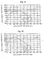
- Comparative Example 5 a bag was prepared on the basis of the bag of Example 2 such that the flow regulator covered only about 90% of the diameter of the inflator head. The result is shown in Fig. 16 .
- the deployment speed is generally high in contrast to Examples 1 and 2; it is remarkably high as compared with the bag of this invention particularly at a point where the deployment distance is 200 - 25 mm.
- the reverse roll type folding system was used as the folding system which allows the bag to deploy with less ease and the bellows type folding system was used as the folding system which allows the bag to deploy with ease.
- the reverse roll type folding system as the folding system which allows the bag to deploy with less ease
- the forward roll type folding system Fig. 10
- Fig. 17 (a) shows usual bellows type folding.
- Figs. 17 (b) and (c) show modifications of the bellows type folding, wherein the front ends 90 are inserted into the bellows from outside or inside and held therein. Therefore, the systems shown in Figs.
- FIG. 17 (b) and (c) may be employed as systems which allow the bag to deploy with less ease and the one shown in Fig. 17 (a) as a system which allows the bag to deploy with ease.
- the bag was folded first by the method allowing the bag to deploy with ease and then by the method allowing it to deploy with less ease; however, the order may be reversed.
- the bag is usually folded on the occupant-associated panel; however, it may be folded on the inflator-associated panel.
- the tethers are disposed at places clear of the spouting direction of gas from the flow regulator, the effect of flow regulation due to the flow regulator is not spoiled by the tethers, reliably leading the gas flow radially toward the outer peripheral edge of the bag. Thereby, the initial deployment speed of the bag moving toward the occupant-associated panel can be reduced.
- the folding system which allows the bag to deploy with less ease is employed in the spouting direction of gas from the flow regulator, the gas flow can be uniformly lead sideways, thereby reducing the deployment speed of the bag moving toward the occupant-associated panel.
Landscapes
- Engineering & Computer Science (AREA)
- Mechanical Engineering (AREA)
- Air Bags (AREA)
Description
- A kind of bag for a vehicle air bag device is known which comprises an occupant-associated panel and an inflator-associated panel which are joined together along their peripheral edges to form a flexible bag construction which is inflatable into a three-dimensional form (see
JP-A-51-31581 - In said bag for a vehicle air bag device, the occupant -associated panel and inflator-associated panel are connected by tethers. The intention is intended to prevent the spacing between the occupant-associated panel and the inflator-associated panel from becoming greater than the length of the tethers when the bag is inflated.
- Thus, the deployment distance of the bag, i.e., the amount of jump-out of the occupant-associated panel can be controlled by the tethers. (The distance from the plane of the steering wheel at that place on the occupant-associated panel which is nearest to the occupant is called the deployment distance.) However, with tethers alone, the deployment speed of the bag cannot be reduced. (The speed at which that place on the occupant-associated panel which is farthest from the plane of the steering wheel moves in the direction orthogonal to the plane of the steering wheel, i.e., axially of the steering wheel is called the deployment speed.) If the deployment speed is high, there is the possibility of the bag, when inflated, coming into contact with the occupant at a relatively high speed depending on the occupant's posture. Further, with the tethers alone, it cannot be expected that the bag will quickly spread toward its outer periphery, i.e., in the direction orthogonal to the jump-out direction, for example, toward the occupant's abdominal region.
- Therefore, in order to decrease the deployment speed and secure quick spreading in the direction orthogonal to the jump-out direction, some of the known bags for vehicle air bag devices include a flow regulator adapted to divert the gas flow in the vicinity of the inflator so as to prevent it from directly hitting the occupant-associated panel (
JP-A-53-45574 US-A-5,172,933 ,EP- , andA-0 600 598DE-A-41 21 659 ). - However, it has been found that with the regulator alone, the deployment distance cannot be controlled and that the deployment speed can be reduced only to a limited degree.
- Therefore, it may be contemplated to provide an air bag with tethers and a flow regulator so that the air bag may have the merits of both, in which case, however, the problem is that if the flow regulator is disposed in the spouting direction of gas, the gas flow diverted by the tethers dashes against the tethers, detracting from the effect of flow regulation.
- Therefore, a first object of this invention is to provide an air bag wherein although it combines tethers with a flow regulator, the effect of flow regulation by the flow regulator is not lost and with the air bag considered as a whole, both the deployment distance and the deployment speed are reduced, and the bag quickly spreads toward the outer periphery.
- Further, the bag is suitably folded and stored in a housing installed in the middle of the steering wheel or the like. In this case, the upper and lower sides and the laterally opposite sides of the bag are often folded in a bellows fashion. The bellows type folding allows the folded sides to spread with ease. Therefore, when such bellows type folding is present in the vertically opposite sides and the horizontally opposite sides, the bellows type folded portions in the vertically opposite sides spread smoothly if the spouting direction of gas from the flow regulator is vertical; thus, the gas concentratedly moves in that direction. And the gas which has reached the upper and lower ends of the bag changes its direction to dash against the occupant-associated panel. Thus, with such folding system, the deployment speed of the bag cannot be reduced.
- Accordingly, a second object of the invention is to provide an air bag having a flow regulator, wherein a particular folding system is employed in connection with the spouting direction of the gas flow reverted by the flow regulator, whereby the deployment speed is reduced.
-
DE 44 42 118 A1claim 1 in common with the present invention. - The present invention is defined in appended
claim 1. Further advantageous features are set out in the dependent claims. - As a preferred embodiment of the invention, said flow regulator is a sheet which covers said inflator attaching opening, the middle portion of said sheet having a slack bulging toward said inflator-associated panel, said sheet being joined at at least two places on the peripheral edge thereof to said inflator-associated panel to form joined portions, and the spacing between a place on the peripheral edge of said sheet other than said joined portions and said inflator-associated panel may form openings for the reverted gas flow.
- In this case, said tethers may be joined to said inflator-associated panel at places which are diametrically outside said joined portions, such arrangement being advantageous from the standpoint of manufacture of the bag. Further, said tethers are composed of said flow regulator, and connecting members which connect said flow regulator and said occupant-associated panel at those places on said flow regulator which may be nearer to said occupant-associated panel than are said joined portions.
- Further, according to this invention, a bag for a vehicle air bag device mentioned at the outset is characterised in that in the interior of said bag construction, a flow regulator is disposed which diverts a gas flow spouting from the inflator, said flow regulator being provided with spout openings so that the gas after being diverted may flow in two mutually opposite directions toward the outer periphery of said bag construction, and a first pair of opposed sides of said bag construction are folded in said gas spouting direction and a second pair of opposed sides are folded in the direction orthogonal to said gas spouting direction, the folding of said first pair of sides allowing less easy deployment than the folding of said second pair of sides. Thus, the folding in the spouting direction of the gas from the flow regulator is such that it allows essentially less easy spreading attended by less easy gas flow, while the folding in the direction orthogonal to said spouting direction of the gas flow is such that it allows essentially easy spreading attended by easy gas flow; therefore, the gas spreads relatively uniformly toward the entire outer periphery of the bag. Therefore, the pressure pressing the occupant-associated panel is distributed, and hence the deployment speed of the bag can be greatly reduced.
- In this case, first, said second pair of sides may be folded in a bellows fashion, and then said first pair of sides may be folded in a reverse roll fashion. In this case, the bellows type folding is the folding which allows easy spreading, and the reverse roll type folding is the folding which allows less easy spreading.
- Further, in this case, said occupant-associated panel and said inflator-associated panel are connected together by tethers which prevent the distance between said two panels from exceeding a predetermined length, said tethers being disposed at positions not to obstruct the gas flow diverted by the flow regulator. This arrangement enhances the effect of reduction of the deployment speed of the bag.
- In the thus-folded bag, advantageously the projecting height of said flow regulator is not more than 2/3 of the projecting height of said occupant-associated panel. If the projecting height of said flow regulator exceeds 2/3, then the flow regulating effect is considerably decreased, increasing the deployment speed of the bag.
- Further, advantageously the width of said flow regulator is greater than the diameter of said inflator head. If the width of said flow regulator should be less than the diameter of said inflator head, this also detracts from the flow regulating effect and increases the deployment speed of the bag.
- Further, in said various kinds of bags, said flow regulator may be made of a material which is impermeable to gas. With this arrangement, since the gas does not permeate the flow regulator, it is diverted without fail.
- Further, in each of said bags for vehicle air bag devices, it is preferable that the deployment speed be 150 km/h or below at a point where the deployment distance is 200 mm or above. In this case, the occupant-associated panel is prevented from coming into heavy contact with the occupant's face or the like.
-
-
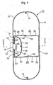
Fig. 1 is a cross-sectional view showing a bag for a vehicle air bag device in its inflated state according to an embodiment of the invention; -
Fig. 2 is a sectional view taken along the line II-II inFig. 1 ; -
Fig. 3 is a sectional view taken along the line III-III inFig. 2 ; -
Fig. 4 is a perspective view of said bag; -
Fig. 5 is a sectional view, similar toFig. 1 , showing a bag according to another embodiment of the invention; -
Fig. 6 shows a folding system for the bag of Example 1, (a) showing the first folding step, (b) showing the second folding step; -
Fig. 7 is a graph showing the deployment speed of the bags of Example 1 and Comparative Example 1; -
Fig. 8 is a view, similar toFig. 6 , showing a folding system for the bag of Example 2; -
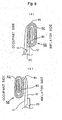
Fig. 9 is a schematic view showing a reverse roll folding system, (a) showing the state before reversion to the occupant-associated panel, (b) showing the state after reversion; -
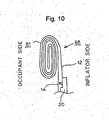
Fig. 10 is a schematic view showing a forward roll folding system; -
Fig. 11 is a view, similar toFig. 6 , showing a folding system for the bag of Comparative Example 2; -
Fig. 12 is a graph showing the deployment speed of the bags of Example 2 and Comparative Example 2; -
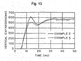
Fig. 13 is a graph showing vertical expansion of the bags of Examples 2 and 3; -
Fig. 14 is a graph showing the deployment speed of the bag of Example 4; -
Fig. 15 is a graph showing the deployment speed of the bag of Comparative Example 4; -
Fig. 16 is a graph showing the deployment speed of the bag of Comparative Example 5; and -
Fig. 17 is a schematic view showing various folding systems of bellows type. -
Figs. 1 through 4 show a bag for a vehicle air bag device according to an embodiment of this invention. - The
bag 10 comprises an inflator-associatedpanel 12 and an occupant-associatedpanel 14. Thesepanels panels circular port 18, in which thehead 22 of the inflator 20 is inserted. The gas spouting from the inflator 20 inflates theair bag 10 into a three-dimensional form, as shown. - The
numerals panel 12 and the occupant-associatedpanel 14 and prevent the distance between thepanels tethers circular port 18. Thereby, when thebag 10 has been deployed into the inflation-completed state, it retains a uniform flat shape, as shown. In this embodiment, thetethers tether forming cloth 28 sewn to the inflator-associatedpanel 12, and a secondtether forming cloth 30 sewn to the occupant-associatedpanel 14. The firsttether forming cloth 28 comprises acircular base portion 31, and twoleg portions 32 extending diametrically outward from two opposed places on the peripheral edge of saidbase portion 31 and having a width less than the diameter of saidbase portion 31, saidbase portion 31 being sewn to the inflator-associatedpanel 12. Similarly, the secondtether forming cloth 30 comprises acircular base portion 34, and twoleg portions 36 extending diametrically outward from two opposed places on the peripheral edge of saidbase portion 34 and having a width less than the diameter of saidbase portion 34, saidbase portion 34 being sewn to the occupant-associatedpanel 14. And two pairs ofleg portions tethers - The numeral 40 denotes a flow regulator made of a flexible material, such as cloth. The
flow regulator 40 is positioned such that when thebag 10 is inflated, the flow regulator is at some distance from the inflator-associatedpanel 12. Theflow regulator 40 has a width greater than the diameter of theinflator attaching opening 18, covering the latter. Theflow regulator 40 is formed as a portion of a flowregulator forming cloth 42. The flowregulator forming cloth 42 comprises acircular base portion 44, and twoleg portions 46 extending diametrically outward from two opposed places on the peripheral edge of saidbase portion 44. Thisbase portion 44 is sewn from above thebase portion 31 of said tether to the inflator-associatedpanel 12. The free ends of the twoleg portions 46 are sewn together as at 48, thereby providing theannular flow regulator 40. In this manner, theflow regulator 40 is joined at its twoopposite sides panel 12 but it is not sewn at the otheropposed sides panel 12. Thesenon-sewn sides 52 form spout openings for gas flow. - Disposed on the
base portion 44 of the flowregulator forming cloth 42 is a reinforcingcloth 53 of substantially the same shape as said base portion. This reinforcingcloth 53 is sewn from above thebase portion 31 of the firsttether forming cloth 28 and thebase portion 44 of the flowregulator forming cloth 42 to the inflator-associatedpanel 12. - The gas spouting from the inflator 20 dashes against the top 49 and joined
portions 50 of saidflow regulator 40 and is thereby diverted, then flowing diametrically outward through thespout openings 52. Thus, the gas flow does not directly push the occupant-associatedpanel 14 toward the occupant. Therefore, the speed at which the occupant-associated panel moves to the occupant can be reduced. - As is obvious from the above description, the
tethers spout openings 52. That is, thetethers places 50 where theflow regulator 40 is joined to the inflator-associatedpanel 12. Therefore, the gas flow diverted by theflow regulator 40 and passing through the spout openings 52 (see arrows inFig. 2 ) is not obstructed by thetethers panel 14 by means of theflow regulator 40. - In the above embodiment, the flow regulator and tethers have been separately prepared. Alternatively, however, as shown in
Fig. 5 , theopposite sides 50 of theflow regulator 40 may be connected to the occupant-associatedpanel 14 by connectingmembers 54 similar to the secondtether forming cloth 30 shown inFig. 1 . In that case, theflow regulator 40 and the connectingmembers 54 cooperate with each other to constitute the tether. - Though not shown, the bag body may have tethers alone attached thereto, and separately therefrom, an inflator having a flow regulator attached thereto is prepared, said inflator being attached to the inflator-associated panel to position the flow regulator within the bag.
- The diameters of the inflator-associated panel and occupant-associated panel are 500 - 800 mm in the flat state of the bag. And the size of the flow regulator is such that the width is 50 - 300 mm and the length is 50 - 400 mm, which size is preferable from the standpoint of reducing the deployment speed of the bag. In this case, the "length" is the length of the flow regulator as measured between the sewn portions closest to the peripheral edge when the base portion of the flow regulator forming cloth is sewn to the inflator-associated panel, i.e., the length of slack of the flow regulator inflated toward the occupant-associated panel. Further, the tethers are 150 - 300 mm long, for example.
- Tests were made using the bag of
Figs. 1 through 4 to prove that the deployment speed is reduced. In that case, the flow regulator used was 250 mm wide and 250 mm long. This width is considerably great, as compared with the diameter of the opening, which is 90 mm, for the inflator. Further, the projecting height of the flow regulator is about 1/3 of the projecting height of the occupant-associated panel. And the bag was positioned to allow the gas flow after being regulated to move vertically. That is, thespout openings 52 in theflow regulator 40 were vertically directed and thetethers bag 10 were folded onto the occupant-associatedpanel 14 in a bellows fashion, as shown inFig. 6 (a) . That is, the upper and lower sides of thebag 10 were folded at a series ofplaces bag 10 to the upper and lower peripheral edges, thereby providing a plurality of foldedpieces panel 14. Then, as shown inFig. 6 (b) , the oppositelateral sides 65 of the foldedbody 64 thus obtained were folded on the occupant-associatedpanel 14 likewise in a bellows fashion. The thus-folded bag is referred to as Example 1. On the other hand, the air bag of comparative Example 1 differs from Example 1 only in that the tethers are disposed outside the gas spout opening in the flow regulator (that is, the tethers are in a position to obstruct the spouting of gas); in the other respects, it is the same as in Example 1. - In the bags of Example 1 and Comparative Example 1, gas was evolved from the inflator, causing the gas flow to deploy the bag, and the deployment speed was measured. The result is shown in
Fig. 7 . In the case of Example 1, the deployment speed continued to decrease from the time when the deployment distance was 110 mm to the time when it was 250 mm, and at the point where the deployment distance was about 250 mm, the deployment speed decreased to 90 km/h. In contrast thereto, in the case of Comparative Example 1, the deployment speed was 160 km/h at a point where the deployment distance was 250 mm. Thus, it is seen that by disposing the tethers at places clear of the gas spouting from the flow regulator, the deployment speed of the bag, particularly the deployment speed at a point nearer to the occupant, can be greatly reduced. - As in Example 1, the bag shown in
Figs. 1 through 4 (in which bag the flow regulator was 170 mm wide and 180 mm long) was used and it was positioned such that the direction of the gas flow after flow regulation was vertical. However, the folding system used differed from that used in Example 1. That is, as shown inFig. 8 (a) , first, the oppositelateral sides 66 of the bag were folded onto the occupant-associatedpanel 14 in a bellows fashion, and then, the upper andlower sides 70 of the foldedbody 68 thus obtained were folded using a reverse roll type, as shown inFig. 8 (b) . - The "reverse roll type" folding mentioned herein refers to a state in which, as shown in
Fig. 9 (a) , the terminal end of the side of the bag is wound and folded onto the side of the inflator-associatedpanel 12. Whereas the folding system in which, as shown inFig. 10 , the terminal end of the side of the bag is wound and folded onto the side of the occupant-associatedpanel 14 is called the forward roll type folding system, it is called the "reverse" roll type folding system in that the bag is reversely folded. To describe in more detail with reference to the drawings, in the case where the reverse roll type folding is to be effected in the upper andlower sides 70 of the bag, as shown inFig. 8 (b) , the upper andlower sides 70 of the foldedbody 68 shown inFig. 8 (a) are successively folded with the front ends 80 thereof disposed inside, thereby forming rolls 82. This is the state shown inFig. 9 (a) . And from this state, eachroll 82 is reversed over itsbase 84 to the side of the occupant-associatedpanel 14, thereby establishing the state shown inFigs. 9 (b) and8 (b) .Fig. 9 (a) and Fig. 9 (b) each show the reverse roll type folding. In practice, for the sake of convenience of receiving the folded bag, the way of folding shown inFig. 9 (b) is employed more often. In the reverse roll type folding, even if the gas evolved in theinflator 20 pushes the occupant-associatedpanel 14 as indicated by the arrow inFig. 9 (a) , theroll 82 is present on the side opposite to the direction of push, forming a resistance to prevent the occupant-associatedpanel 14 from readily moving forward. In contrast thereto, in the forward roll type folding, when the occupant-associatedpanel 14 is pushed in the direction of arrow, as can be seen fromFig. 10 , theroll 81 is moved forward. After all, the occupant-associatedpanel 14 easily moves forward. Thus, the reverse roll type folding provides less easy unfolding than the forward roll type folding. - As Comparative Example 2, a bag having tethers but not having a flow regulator was used, and the folding method used was such that, as shown in
Fig. 11 , the upper andlower sides 71 of the bag were folded toward the occupant-associatedpanel 14 in a bellows fashion and then the oppositelateral sides 74 of the foldedbody 72 thus obtained were folded toward the occupant-associatedpanel 14 in a reverse roll fashion. - The result is shown in
Fig. 12 . The bag of Example 2 has its deployment speed reduced as a whole as compared with the bag of Comparative Example 2. It is greatly reduced particularly at a point where the deployment distance is 200 - 300 mm or thereabouts. The reason is that since the folding system which allows the bag to deploy with less ease is employed in the gas spouting direction, the gas flows relatively uniformly throughout toward the entire outer periphery of the bag, producing a decreased pushing force on the occupant-associatedpanel 14. In addition, the vertical deployment of the bag is also quick. In addition, the difference in the amount of maximum jump-out between Example 2 and Comparative Example 2 is due to the difference in tether length. - In Example 3, the spouting direction of gas from the flow regulator was horizontal and the folding system used was such that first, the upper and lower sides of the bag were folded in a bellows fashion and then the opposite lateral sides of the resulting folded body were folded in a reverse roll fashion. A comparison between Examples 2 and 3 is shown in
Fig. 13 . The width of the initial vertical spread of the bag at the beginning of deployment is greater in the case of Example 2. This shows that the vertical spread is a little quicker in the case of the bag of Example 2. - The bag used was the same as in Example 2 except that it has no tethers and thus does not present an embodiment of the present invention. The bag was folded as in Example 2. The result is shown in
Fig. 14 . As compared with Comparative Example 2 (seeFig. 12 ), the overall deployment speed is decreased. And it is seen that even if the bag has no tethers, since the folding system which allows the bag to deploy with less ease is employed in the spouting direction of gas from the flow regulator, there is obtained some effect of reduction of deployment speed; however, the amount of projection toward the occupant is substantially increased owing to the absence of tethers. - In addition, as Comparative Example 4, a bag was prepared on the basis of the bag of Example 2 such that the projecting height of the flow regulator exceeded 2/3 of the projecting height of the occupant-associated panel. The result is shown in
Fig. 15 . Further, as Comparative Example 5, a bag was prepared on the basis of the bag of Example 2 such that the flow regulator covered only about 90% of the diameter of the inflator head. The result is shown inFig. 16 . In each case, the deployment speed is generally high in contrast to Examples 1 and 2; it is remarkably high as compared with the bag of this invention particularly at a point where the deployment distance is 200 - 25 mm. - In Examples 2 and 3, the reverse roll type folding system was used as the folding system which allows the bag to deploy with less ease and the bellows type folding system was used as the folding system which allows the bag to deploy with ease. Alternatively, it is possible to use the reverse roll type folding system as the folding system which allows the bag to deploy with less ease and the forward roll type folding system (
Fig. 10 ) as the folding system which allows the bag to deploy with ease. Further,Fig. 17 (a) shows usual bellows type folding.Figs. 17 (b) and (c) show modifications of the bellows type folding, wherein the front ends 90 are inserted into the bellows from outside or inside and held therein. Therefore, the systems shown inFigs. 17 (b) and (c) may be employed as systems which allow the bag to deploy with less ease and the one shown inFig. 17 (a) as a system which allows the bag to deploy with ease. Further, in Examples 2 and 3, the bag was folded first by the method allowing the bag to deploy with ease and then by the method allowing it to deploy with less ease; however, the order may be reversed. Further, in the bellows type folding, reverse roll type folding, and other forms of folding used in this invention, the bag is usually folded on the occupant-associated panel; however, it may be folded on the inflator-associated panel. - In the bag for a vehicle air bag device according to this invention, since the tethers are disposed at places clear of the spouting direction of gas from the flow regulator, the effect of flow regulation due to the flow regulator is not spoiled by the tethers, reliably leading the gas flow radially toward the outer peripheral edge of the bag. Thereby, the initial deployment speed of the bag moving toward the occupant-associated panel can be reduced.
- Further, in the bag for a vehicle air bag device according to this invention, since the folding system which allows the bag to deploy with less ease is employed in the spouting direction of gas from the flow regulator, the gas flow can be uniformly lead sideways, thereby reducing the deployment speed of the bag moving toward the occupant-associated panel.
Claims (4)
- A bag for a vehicle air bag device wherein an occupant-associated panel (14) and an inflator-associated panel (12) are joined together along their peripheral edges to provide a flexible bag construction which can be inflated into a three-dimensional form, said inflator-associated panel (12) is formed with an opening for attaching an inflator (20), wherein
a flow regulator (40) is disposed in the interior of said bag construction to divert the gas flow spouted from the inflator toward the outer periphery of said bag construction, said flow regulator (40) comprising a base portion (44) having an opening for inserting the head (22) of the inflator (20) and flow inflator members (46) extending from said base portion (44)
said occupant-associated panel (14) and said inflator-associated panel (12) are connected by tethers (24, 26) which prevent the spacing between the two panels (12, 14) from exceeding a predetermined length, and
said tethers (24, 26) are disposed at positions where they do not obstruct the flow of gas diverted by said flow regulator (40),
characterized in that
the base portion (44) of the flow regulator (40) is sewn together with a reinforcing cloth (53) to the inflator-associated panel (12), and
the flow inflator members (46) comprise at least two leg portions (46) extending from the base portion (44) whose free ends (48) are sewn together. - The bag of claim 1, wherein
said flow regulator (40) is a sheet which covers said inflator attaching opening (18),
the middle portion of said sheet has a slack bulging toward said inflator-associated panel (12),
said sheet is joined at at least two places on the peripheral edge thereof to said inflator-associated panel (12) to form joined portions, and
the spacing between a place on the peripheral edge of said sheet other than said joined portions and said inflator-associated panel (12) forms openings (52) for the reverted gas flow. - The bag of claim 2, wherein said tethers (24, 26) are joined to said inflator-associated panel (12) at places which are diametrically outside said joined portions.
- The bag of claim 2, wherein said tethers (24, 26) are composed of said flow regulator (40), and connecting members which connect said flow regulator (40) and said occupant-associated panel (14) at those places on said flow regulator (40) which are nearer to said occupant-associated panel (14) than are said joined portions.
Priority Applications (1)
| Application Number | Priority Date | Filing Date | Title |
|---|---|---|---|
| DE69638006T DE69638006D1 (en) | 1996-03-29 | 1996-03-29 | Bag for vehicle Air bag device with gas flow regulator made of fabric |
Applications Claiming Priority (2)
| Application Number | Priority Date | Filing Date | Title |
|---|---|---|---|
| PCT/JP1996/000867 WO1997036768A1 (en) | 1996-03-29 | 1996-03-29 | Bag for an air bag unit for a vehicule |
| EP96907727A EP0829395B1 (en) | 1996-03-29 | 1996-03-29 | Bag for an air bag unit for a vehicle |
Related Parent Applications (2)
| Application Number | Title | Priority Date | Filing Date |
|---|---|---|---|
| EP96907727A Division EP0829395B1 (en) | 1996-03-29 | 1996-03-29 | Bag for an air bag unit for a vehicle |
| EP96907727.0 Division | 1997-10-09 |
Publications (3)
| Publication Number | Publication Date |
|---|---|
| EP1439097A2 EP1439097A2 (en) | 2004-07-21 |
| EP1439097A3 EP1439097A3 (en) | 2004-08-11 |
| EP1439097B1 true EP1439097B1 (en) | 2009-08-19 |
Family
ID=14153135
Family Applications (1)
| Application Number | Title | Priority Date | Filing Date |
|---|---|---|---|
| EP04005470A Expired - Lifetime EP1439097B1 (en) | 1996-03-29 | 1996-03-29 | Bag for vehicle air bag device with a fabric diffuser |
Country Status (5)
| Country | Link |
|---|---|
| EP (1) | EP1439097B1 (en) |
| JP (1) | JP3578463B2 (en) |
| KR (1) | KR100440690B1 (en) |
| AU (1) | AU734524B2 (en) |
| DE (2) | DE69638006D1 (en) |
Cited By (1)
| Publication number | Priority date | Publication date | Assignee | Title |
|---|---|---|---|---|
| US9283921B2 (en) | 2013-11-21 | 2016-03-15 | Ford Global Technologies, Llc | Driver airbag module having multiple deployment paths |
Families Citing this family (3)
| Publication number | Priority date | Publication date | Assignee | Title |
|---|---|---|---|---|
| JP4595520B2 (en) * | 2004-12-15 | 2010-12-08 | タカタ株式会社 | Airbag device |
| KR20140014516A (en) * | 2012-07-24 | 2014-02-06 | 현대모비스 주식회사 | Driver airbag apparatus |
| DE102013015223A1 (en) * | 2013-09-13 | 2015-03-19 | Autoliv Development Ab | Airbag with an airbag cover and a deflector element |
Family Cites Families (4)
| Publication number | Priority date | Publication date | Assignee | Title |
|---|---|---|---|---|
| JPH0667710B2 (en) * | 1989-08-25 | 1994-08-31 | 豊田合成株式会社 | Air bag strap detection device |
| JP3151907B2 (en) * | 1992-01-31 | 2001-04-03 | タカタ株式会社 | Leg protection for vehicle occupants |
| JPH061010U (en) * | 1992-06-17 | 1994-01-11 | 株式会社東海理化電機製作所 | Airbag device bag |
| DE4442118B4 (en) * | 1993-11-26 | 2004-07-01 | Toyoda Gosei Co., Ltd., Nishikasugai | air bag |
-
1996
- 1996-03-29 DE DE69638006T patent/DE69638006D1/en not_active Expired - Lifetime
- 1996-03-29 EP EP04005470A patent/EP1439097B1/en not_active Expired - Lifetime
- 1996-03-29 DE DE69635703T patent/DE69635703T2/en not_active Expired - Lifetime
- 1996-03-29 AU AU51226/96A patent/AU734524B2/en not_active Ceased
- 1996-03-29 KR KR1019970708538A patent/KR100440690B1/en not_active Expired - Fee Related
- 1996-03-29 JP JP53510897A patent/JP3578463B2/en not_active Expired - Fee Related
Cited By (1)
| Publication number | Priority date | Publication date | Assignee | Title |
|---|---|---|---|---|
| US9283921B2 (en) | 2013-11-21 | 2016-03-15 | Ford Global Technologies, Llc | Driver airbag module having multiple deployment paths |
Also Published As
| Publication number | Publication date |
|---|---|
| KR100440690B1 (en) | 2004-09-18 |
| DE69635703D1 (en) | 2006-03-30 |
| DE69638006D1 (en) | 2009-10-01 |
| DE69635703T2 (en) | 2006-09-14 |
| KR19990022059A (en) | 1999-03-25 |
| EP1439097A3 (en) | 2004-08-11 |
| AU5122696A (en) | 1997-10-22 |
| JP3578463B2 (en) | 2004-10-20 |
| EP1439097A2 (en) | 2004-07-21 |
| AU734524B2 (en) | 2001-06-14 |
Similar Documents
| Publication | Publication Date | Title |
|---|---|---|
| EP0829395B1 (en) | Bag for an air bag unit for a vehicle | |
| US7134691B2 (en) | Air bag cushion including break-away tethers | |
| US7708311B2 (en) | Airbag for front passenger's seat | |
| KR100313751B1 (en) | Airbag with inflator | |
| EP1660355B1 (en) | Gas flow deflection apparatus and method for airbag systems | |
| CA2172119C (en) | Folded air bag | |
| US7942443B2 (en) | Airbag system | |
| US8382154B2 (en) | Airbag device | |
| KR100558179B1 (en) | Airbag Tether Release Assembly | |
| US8684407B2 (en) | Air bag with height adaptive tether | |
| US5865465A (en) | Air-bag | |
| US6237936B1 (en) | Vehicle inflatable restraint system | |
| US20070205590A1 (en) | Cushion shaping sleeve and tether for airbags | |
| US20070205591A1 (en) | Airbag apparatus for a front passenger's seat | |
| KR20070058573A (en) | Airbag Cushion with Cinch Tube to Reduce Delocation Effect | |
| WO2006073534A2 (en) | Airbag cushion with adaptive venting for reduced out-of-position effects | |
| EP3300957B1 (en) | External tether airbag | |
| EP4173898A1 (en) | Airbag assembly and vehicle seat assembly | |
| JP2010535121A (en) | Airbag for vehicle occupant protection | |
| JP3758665B2 (en) | Bag for a vehicle airbag device | |
| AU734524B2 (en) | Bag for vehicle air bag device | |
| US6802528B2 (en) | Air bag cushion energy diverter | |
| JP4793124B2 (en) | Passenger airbag | |
| JP4979066B2 (en) | Airbag folding method, airbag and airbag device | |
| JPWO1997036768A1 (en) | Bag for vehicle airbag device |
Legal Events
| Date | Code | Title | Description |
|---|---|---|---|
| PUAI | Public reference made under article 153(3) epc to a published international application that has entered the european phase |
Free format text: ORIGINAL CODE: 0009012 |
|
| PUAL | Search report despatched |
Free format text: ORIGINAL CODE: 0009013 |
|
| AC | Divisional application: reference to earlier application |
Ref document number: 0829395 Country of ref document: EP Kind code of ref document: P |
|
| AK | Designated contracting states |
Kind code of ref document: A2 Designated state(s): DE FR GB |
|
| AK | Designated contracting states |
Kind code of ref document: A3 Designated state(s): DE FR GB |
|
| 17P | Request for examination filed |
Effective date: 20050209 |
|
| AKX | Designation fees paid |
Designated state(s): DE FR GB |
|
| 17Q | First examination report despatched |
Effective date: 20071220 |
|
| GRAP | Despatch of communication of intention to grant a patent |
Free format text: ORIGINAL CODE: EPIDOSNIGR1 |
|
| GRAS | Grant fee paid |
Free format text: ORIGINAL CODE: EPIDOSNIGR3 |
|
| GRAA | (expected) grant |
Free format text: ORIGINAL CODE: 0009210 |
|
| AC | Divisional application: reference to earlier application |
Ref document number: 0829395 Country of ref document: EP Kind code of ref document: P |
|
| AK | Designated contracting states |
Kind code of ref document: B1 Designated state(s): DE FR GB |
|
| REG | Reference to a national code |
Ref country code: GB Ref legal event code: FG4D |
|
| REF | Corresponds to: |
Ref document number: 69638006 Country of ref document: DE Date of ref document: 20091001 Kind code of ref document: P |
|
| PGFP | Annual fee paid to national office [announced via postgrant information from national office to epo] |
Ref country code: FR Payment date: 20100324 Year of fee payment: 15 |
|
| PLBE | No opposition filed within time limit |
Free format text: ORIGINAL CODE: 0009261 |
|
| STAA | Information on the status of an ep patent application or granted ep patent |
Free format text: STATUS: NO OPPOSITION FILED WITHIN TIME LIMIT |
|
| PGFP | Annual fee paid to national office [announced via postgrant information from national office to epo] |
Ref country code: GB Payment date: 20100322 Year of fee payment: 15 |
|
| 26N | No opposition filed |
Effective date: 20100520 |
|
| GBPC | Gb: european patent ceased through non-payment of renewal fee |
Effective date: 20110329 |
|
| REG | Reference to a national code |
Ref country code: FR Ref legal event code: ST Effective date: 20111130 |
|
| PG25 | Lapsed in a contracting state [announced via postgrant information from national office to epo] |
Ref country code: FR Free format text: LAPSE BECAUSE OF NON-PAYMENT OF DUE FEES Effective date: 20110331 |
|
| PG25 | Lapsed in a contracting state [announced via postgrant information from national office to epo] |
Ref country code: GB Free format text: LAPSE BECAUSE OF NON-PAYMENT OF DUE FEES Effective date: 20110329 |
|
| REG | Reference to a national code |
Ref country code: DE Ref legal event code: R084 Ref document number: 69638006 Country of ref document: DE Effective date: 20120117 |
|
| PGFP | Annual fee paid to national office [announced via postgrant information from national office to epo] |
Ref country code: DE Payment date: 20130327 Year of fee payment: 18 |
|
| REG | Reference to a national code |
Ref country code: DE Ref legal event code: R119 Ref document number: 69638006 Country of ref document: DE |
|
| REG | Reference to a national code |
Ref country code: DE Ref legal event code: R119 Ref document number: 69638006 Country of ref document: DE Effective date: 20141001 |
|
| PG25 | Lapsed in a contracting state [announced via postgrant information from national office to epo] |
Ref country code: DE Free format text: LAPSE BECAUSE OF NON-PAYMENT OF DUE FEES Effective date: 20141001 |