EP1438905A1 - A clip for and a lanyard - Google Patents
A clip for and a lanyard Download PDFInfo
- Publication number
- EP1438905A1 EP1438905A1 EP04250034A EP04250034A EP1438905A1 EP 1438905 A1 EP1438905 A1 EP 1438905A1 EP 04250034 A EP04250034 A EP 04250034A EP 04250034 A EP04250034 A EP 04250034A EP 1438905 A1 EP1438905 A1 EP 1438905A1
- Authority
- EP
- European Patent Office
- Prior art keywords
- clip
- lanyard
- web end
- cord
- pins
- Prior art date
- Legal status (The legal status is an assumption and is not a legal conclusion. Google has not performed a legal analysis and makes no representation as to the accuracy of the status listed.)
- Granted
Links
- 230000000087 stabilizing effect Effects 0.000 claims abstract description 8
- 230000001419 dependent effect Effects 0.000 claims 1
- 230000013011 mating Effects 0.000 abstract description 2
- 230000002093 peripheral effect Effects 0.000 description 5
- 238000000034 method Methods 0.000 description 3
- 238000004026 adhesive bonding Methods 0.000 description 1
- 238000003491 array Methods 0.000 description 1
- 238000005452 bending Methods 0.000 description 1
- 238000010276 construction Methods 0.000 description 1
- 238000009434 installation Methods 0.000 description 1
- 229920000642 polymer Polymers 0.000 description 1
- 230000002028 premature Effects 0.000 description 1
Images


Classifications
-
- A—HUMAN NECESSITIES
- A44—HABERDASHERY; JEWELLERY
- A44B—BUTTONS, PINS, BUCKLES, SLIDE FASTENERS, OR THE LIKE
- A44B99/00—Subject matter not provided for in other groups of this subclass
-
- Y—GENERAL TAGGING OF NEW TECHNOLOGICAL DEVELOPMENTS; GENERAL TAGGING OF CROSS-SECTIONAL TECHNOLOGIES SPANNING OVER SEVERAL SECTIONS OF THE IPC; TECHNICAL SUBJECTS COVERED BY FORMER USPC CROSS-REFERENCE ART COLLECTIONS [XRACs] AND DIGESTS
- Y10—TECHNICAL SUBJECTS COVERED BY FORMER USPC
- Y10T—TECHNICAL SUBJECTS COVERED BY FORMER US CLASSIFICATION
- Y10T24/00—Buckles, buttons, clasps, etc.
- Y10T24/13—Article holder attachable to apparel or body
- Y10T24/1374—Neck supported holder
-
- Y—GENERAL TAGGING OF NEW TECHNOLOGICAL DEVELOPMENTS; GENERAL TAGGING OF CROSS-SECTIONAL TECHNOLOGIES SPANNING OVER SEVERAL SECTIONS OF THE IPC; TECHNICAL SUBJECTS COVERED BY FORMER USPC CROSS-REFERENCE ART COLLECTIONS [XRACs] AND DIGESTS
- Y10—TECHNICAL SUBJECTS COVERED BY FORMER USPC
- Y10T—TECHNICAL SUBJECTS COVERED BY FORMER US CLASSIFICATION
- Y10T24/00—Buckles, buttons, clasps, etc.
- Y10T24/39—Cord and rope holders
-
- Y—GENERAL TAGGING OF NEW TECHNOLOGICAL DEVELOPMENTS; GENERAL TAGGING OF CROSS-SECTIONAL TECHNOLOGIES SPANNING OVER SEVERAL SECTIONS OF THE IPC; TECHNICAL SUBJECTS COVERED BY FORMER USPC CROSS-REFERENCE ART COLLECTIONS [XRACs] AND DIGESTS
- Y10—TECHNICAL SUBJECTS COVERED BY FORMER USPC
- Y10T—TECHNICAL SUBJECTS COVERED BY FORMER US CLASSIFICATION
- Y10T24/00—Buckles, buttons, clasps, etc.
- Y10T24/39—Cord and rope holders
- Y10T24/3916—One-piece
-
- Y—GENERAL TAGGING OF NEW TECHNOLOGICAL DEVELOPMENTS; GENERAL TAGGING OF CROSS-SECTIONAL TECHNOLOGIES SPANNING OVER SEVERAL SECTIONS OF THE IPC; TECHNICAL SUBJECTS COVERED BY FORMER USPC CROSS-REFERENCE ART COLLECTIONS [XRACs] AND DIGESTS
- Y10—TECHNICAL SUBJECTS COVERED BY FORMER USPC
- Y10T—TECHNICAL SUBJECTS COVERED BY FORMER US CLASSIFICATION
- Y10T24/00—Buckles, buttons, clasps, etc.
- Y10T24/39—Cord and rope holders
- Y10T24/3987—Loop, adjustable
-
- Y—GENERAL TAGGING OF NEW TECHNOLOGICAL DEVELOPMENTS; GENERAL TAGGING OF CROSS-SECTIONAL TECHNOLOGIES SPANNING OVER SEVERAL SECTIONS OF THE IPC; TECHNICAL SUBJECTS COVERED BY FORMER USPC CROSS-REFERENCE ART COLLECTIONS [XRACs] AND DIGESTS
- Y10—TECHNICAL SUBJECTS COVERED BY FORMER USPC
- Y10T—TECHNICAL SUBJECTS COVERED BY FORMER US CLASSIFICATION
- Y10T24/00—Buckles, buttons, clasps, etc.
- Y10T24/47—Strap-end-attaching devices
Definitions
- the present invention relates generally to lanyards and more particularly to clips for lanyards that snap onto lanyard ends and are used to hold security or trade show identification badges or the like.
- lanyards are used to suspend identification or security badges, keys, cell phones, or other objects around a person's neck.
- Conventional lanyards include the use of a small cord or rope that is joined together at the cord ends to form a loop that fits over a person's head and around the neck.
- a ring or hook is connected to the formed loop to secure or suspend an object, such as an identification badge, around the person's neck.
- known lanyards and techniques for joining the lanyard cord ends have certain drawbacks.
- known lanyards use multiple components to join the lanyard cord ends resulting in greater complexity of the product, use of special tools, and increased difficulty in the use of the product.
- many of the known multiple components used to join lanyard cord ends are unreliable, have a high initial purchase cost, and an overall high cost application.
- the present invention is directed at overcoming these and other known problems and drawbacks with existing lanyards and specifically the problems associated with joining lanyard cord ends.
- the present invention is directed to a lanyard that uses a single component to join the ends of the lanyard cord.
- the single component referred to as a web end
- the web end uses numerous pins extending out from the web end that will engage with numerous pin pockets after the web end is folded together.
- the lanyard cord ends are trapped between the numerous pins and pin pockets.
- a ring, hook or other attachment member may be connected to the web end to attach an identification badge or other object to the lanyard. With the present invention, the web end is easily attached by hand to the lanyard cord ends without the use of special tools.
- an exemplary embodiment of the invention is depicted as a one-piece web end 10.
- the web end 10 also referred to as a clip, is used to secure together the opposing ends of a lanyard cord. Once secured together, the lanyard forms a loop that may be placed over a person's head and around the neck.
- the web end 10 may also receive an attachment member, discussed below, that can be used to mount or connect an identification badge, tag or other object to the lanyard.
- the web end or clip 10 is depicted in an open, unattached and unsnapped position. In this position, the web end 10 defines an outer surface wall 12, an inner surface wall 14, and opposing ends 16, 18. Located between and connecting the opposing ends 16, 18 of the web end 10 are hinges 20, 21 that permit the opposing ends 16, 18 to fold together. It should be understood that the invention may use fewer hinges to permit the folding together of the ends 16, 18. Located between the hinges 20, 21 is a central portion 43 defining a central aperture 44 that is used to connect an attachment 50 to the web end 10, as shown in FIGS. 5 and 6 and discussed in more detail below. Also depicted in FIG.
- the web end 10 includes integral stabilizing ribs 22 that extend outwardly from the inner surface of the central portion 43.
- the stabilizing ribs 22 engage stabilizing rib recesses 24 formed in the body of the web end 10 to align the opposing ends 16, 18 of the web end 10 when the web end 10 is folded together and attached to the cord ends of the lanyard.
- the stabilizing ribs 22 and rib recesses 24 are positioned near the peripheral edge 30 of the web end 10 and adjacent or in close proximity to the hinges 20, 21.
- the web end 10 is preferably made from a plastic material, polymer, or similar suitable material.
- the web end 10 includes on the inner surface wall 14 a plurality of conical shaped interlocking pins 26 that are spaced apart in an array. Also spaced apart in an array is a plurality of pin pockets or pin receptacles 28.
- the pins 26 and pin pockets 28 are located on both ends 16, 18 of the web end 10 and are positioned on the web end 10 such that when the web end 10 is folded at the hinges 20, 21, and over the cord ends, the pins 26 and pin pockets 28 mate with each other, as illustrated in the embodiment shown in FIGS. 3 and 4.
- the mated plurality of pins 26 and pin pockets 28 will trap and secure the cord ends 40, 42 to the web end 10 and will prevent movement of the cord ends 40, 42 relative to the web end 10 under an applied tension, as shown in FIG. 4.
- the interlocking pins 26 on one end of the web end 10 will pierce through the cord ends 40, 42 and extend into and mate with the pin pockets 28 on the opposing end of the web end 10 to securely hold the web end 10 onto the cord ends 40, 42.
- the cord ends 40, 42 are prevented from being pulled out of the web end 10 under an applied tension.
- each of the pins 26 define a pin tip 32 that extends into the pin pocket 28 and is held in place in the mating pin pocket 28.
- the pin 26 will have a tendency to bend about its base 34 until the tip 32 of the pin 26 contacts that inner wall 36 of the pin pocket 28 at which point the pin 26 is prevented from bending any further. With this construction, the premature pull-out of the cord ends 40, 42 is greatly improved.
- pins 26 have a conical shape and extend outwardly from the inner surface wall 14 of the web end 10
- the pins 26 may take on other various shapes, such as pyramids, columns, squares or similar shapes, and still achieve the desired securement of the cord ends 40, 42 to the web end 10.
- other arrays, configurations, and numbers of pins 26 and pin pockets 28 are possible and may be used with the present invention.
- the web end 10 includes the central aperture 44 located between the hinges 20, 21 for mounting the web end 10 to an attachment member 50, as discussed below.
- the central aperture 44 may take on numerous shapes, such as round, square, geometrical, or non-geometrical configurations, or other similar shapes and configurations, to receive various types of attachment members, as known in the art.
- the web end 10 further may include a plurality of locking tabs 46 extending outwardly from the inner surface wall 14. In the exemplary embodiment, the locking tabs 46 are located around the peripheral edge 30 of the web end 10. It should be understood that the invention is not limited to the illustrated location of the locking tabs 46 as one or more of these tabs could be located at a position on the web end 10 not at the peripheral edge 30.
- These locking tabs 46 are received within a plurality of openings 48 also located in the exemplary embodiment around the peripheral edge 30 of the web end 10 when the web end 10 is folded at the hinges 20, 21. These plurality of locking tabs 46 and openings 48 permit the opposing ends 16, 18 of the web end 10 to interlock and snap together.
- the interlocking of the opposing ends 16, 18 of the web end 10 onto the cord ends 40, 42 is easily accomplished by hand without the use of special tools.
- the cord ends 40, 42 are inserted between the opposing ends 16, 18 of the web end 10.
- the web end 10 is folded at the hinges 20, 21 with the stabilizing ribs 22 aligning with the stabilizing recesses 24.
- the pins 26 and pin pockets 28 on the inner surface wall 14 of the web end 10 secure the cord ends 40, 42 in position by trapping the cord ends between engaging pins 26 and pin pockets 28.
- the plurality of locking tabs 46 and openings 48 positioned along the peripheral edge 30 of the web end 10 interlock with each other and by merely applying hand pressure to the opposing ends 16, 18, cause the opposing ends 16, 18 to snap together, thereby securing and trapping the cord ends 16, 18 within the web end 10.
- the web end 10 of the present invention is more readily installed than other known devices because of this ergonomically advantageous assembly.
- the attachment member 50 includes a loop 52 and a projection 54 extending outwardly from the loop 52.
- the projection 54 is sized and shaped to snap fit into the central aperture 44 of the web end 10 to secure the attachment member 50 onto the web end 10.
- An identification badge or other object may be attached to the loop 52 of attachment member 50. It should be understood that other shapes, designs and styles of attachment member 50 and loop 52, such as uniform, geometric, non-uniform or non-geometric shapes, designs and styles may be used with the present invention.
- a lanyard 70 typically used to secure or suspend from a person's neck a small object, such as an identification badge or tag.
- the lanyard 70 includes a cord, which may be a webbing material 72 that forms a large loop 74 that, in use, is placed over a person's head and around the neck.
- the lanyard 70 defines cord ends 40, 42.
- Mounted to the cord ends 40, 42 of the lanyard 70 is the web end 10 of the present invention. As discussed above, the web end 10 snap fits onto the cord ends 40, 42 and secures the cord ends together.
- mounted to the web end 10 is the attachment member 50 that is used to connect or mount an identification badge or other object, not shown, to the lanyard 70.
- FIGS. 8-19 illustrate various views of alternative designs according to the present invention.
Landscapes
- Details Of Garments (AREA)
- Hooks, Suction Cups, And Attachment By Adhesive Means (AREA)
- Purses, Travelling Bags, Baskets, Or Suitcases (AREA)
Abstract
Description
- The present invention relates generally to lanyards and more particularly to clips for lanyards that snap onto lanyard ends and are used to hold security or trade show identification badges or the like.
- It is known that lanyards are used to suspend identification or security badges, keys, cell phones, or other objects around a person's neck. Conventional lanyards include the use of a small cord or rope that is joined together at the cord ends to form a loop that fits over a person's head and around the neck. There are several known techniques to join the cord ends of the lanyard to form a loop. These techniques include tying or gluing the cord ends together, or using multiple fastener components that must be attached onto the cord ends and then secured together. Typically, a ring or hook is connected to the formed loop to secure or suspend an object, such as an identification badge, around the person's neck.
- These known lanyards and techniques for joining the lanyard cord ends, however, have certain drawbacks. For example, known lanyards use multiple components to join the lanyard cord ends resulting in greater complexity of the product, use of special tools, and increased difficulty in the use of the product. In addition, many of the known multiple components used to join lanyard cord ends are unreliable, have a high initial purchase cost, and an overall high cost application. The present invention is directed at overcoming these and other known problems and drawbacks with existing lanyards and specifically the problems associated with joining lanyard cord ends.
- The present invention is directed to a lanyard that uses a single component to join the ends of the lanyard cord. The single component, referred to as a web end, folds together over the lanyard cord ends and snap fits onto the ends to secure the cord ends together. To secure the cord ends together, the web end uses numerous pins extending out from the web end that will engage with numerous pin pockets after the web end is folded together. The lanyard cord ends are trapped between the numerous pins and pin pockets. A ring, hook or other attachment member may be connected to the web end to attach an identification badge or other object to the lanyard. With the present invention, the web end is easily attached by hand to the lanyard cord ends without the use of special tools.
- Particular embodiments in accordance with this invention will now be described with reference to the accompanying drawings; in which:-
- FIG.1 is an isometric view of an exemplary web end of the present invention.
- FIG.2 is another isometric view of the invention of FIG. 1.
- FIG.3 is an isometric view of the installation of the invention of FIG. 1 onto the cord ends of a lanyard.
- FIG. 4 is a cross-section view of the invention of FIG. 1 installed onto the cord ends of a lanyard.
- FIG. 5 is an isometric exploded view of an attachment that may be mounted onto the invention of FIG. 1.
- FIG. 6 is an isometric view of the assembly of the attachment of FIG. 5 to the invention of FIG. 1.
- FIG. 7 is an isometric view of the assembly of the invention of FIG. 1 and the attachment of FIG. 5 with a lanyard.
- FIGS. 8-11 illustrate various views of an alternative web end according to the present invention.
- FIGS. 12-15 illustrate various views of yet another alternative web end according to the present invention.
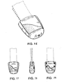
- FIGS. 16-19 illustrate various views of still another alternative web end according to the present invention.
-
- Referring to FIGS. 1 and 2, an exemplary embodiment of the invention is depicted as a one-
piece web end 10. Theweb end 10, also referred to as a clip, is used to secure together the opposing ends of a lanyard cord. Once secured together, the lanyard forms a loop that may be placed over a person's head and around the neck. Theweb end 10 may also receive an attachment member, discussed below, that can be used to mount or connect an identification badge, tag or other object to the lanyard. - As illustrated in FIGS. 1 and 2, the web end or
clip 10 is depicted in an open, unattached and unsnapped position. In this position, theweb end 10 defines anouter surface wall 12, aninner surface wall 14, andopposing ends opposing ends web end 10 are hinges 20, 21 that permit theopposing ends ends hinges central portion 43 defining acentral aperture 44 that is used to connect anattachment 50 to theweb end 10, as shown in FIGS. 5 and 6 and discussed in more detail below. Also depicted in FIG. 1, theweb end 10 includes integral stabilizingribs 22 that extend outwardly from the inner surface of thecentral portion 43. In use, the stabilizingribs 22 engage stabilizingrib recesses 24 formed in the body of theweb end 10 to align theopposing ends web end 10 when theweb end 10 is folded together and attached to the cord ends of the lanyard. In an exemplary embodiment, the stabilizingribs 22 andrib recesses 24 are positioned near theperipheral edge 30 of theweb end 10 and adjacent or in close proximity to thehinges web end 10 is preferably made from a plastic material, polymer, or similar suitable material. - Also shown in FIG. 1, the
web end 10 includes on the inner surface wall 14 a plurality of conicalshaped interlocking pins 26 that are spaced apart in an array. Also spaced apart in an array is a plurality of pin pockets orpin receptacles 28. Thepins 26 andpin pockets 28 are located on bothends web end 10 and are positioned on theweb end 10 such that when theweb end 10 is folded at thehinges pins 26 andpin pockets 28 mate with each other, as illustrated in the embodiment shown in FIGS. 3 and 4. In use, the mated plurality ofpins 26 andpin pockets 28 will trap and secure thecord ends web end 10 and will prevent movement of thecord ends web end 10 under an applied tension, as shown in FIG. 4. In other words, when theends web end 10 are folded onto thecord ends pins 26 on one end of theweb end 10 will pierce through thecord ends pin pockets 28 on the opposing end of theweb end 10 to securely hold theweb end 10 onto thecord ends web end 10 under an applied tension. - Referring to FIG. 4, each of the
pins 26 define apin tip 32 that extends into thepin pocket 28 and is held in place in themating pin pocket 28. As the cord ends 40, 42 are pulled or placed under an applied tension, thepin 26 will have a tendency to bend about itsbase 34 until thetip 32 of thepin 26 contacts thatinner wall 36 of thepin pocket 28 at which point thepin 26 is prevented from bending any further. With this construction, the premature pull-out of thecord ends pins 26 have a conical shape and extend outwardly from theinner surface wall 14 of theweb end 10, thepins 26 may take on other various shapes, such as pyramids, columns, squares or similar shapes, and still achieve the desired securement of thecord ends web end 10. It should also be understood that other arrays, configurations, and numbers ofpins 26 andpin pockets 28 are possible and may be used with the present invention. - Referring back to FIGS. 1 and 2, the
web end 10 includes thecentral aperture 44 located between thehinges web end 10 to anattachment member 50, as discussed below. Thecentral aperture 44 may take on numerous shapes, such as round, square, geometrical, or non-geometrical configurations, or other similar shapes and configurations, to receive various types of attachment members, as known in the art. Theweb end 10 further may include a plurality oflocking tabs 46 extending outwardly from theinner surface wall 14. In the exemplary embodiment, thelocking tabs 46 are located around theperipheral edge 30 of theweb end 10. It should be understood that the invention is not limited to the illustrated location of thelocking tabs 46 as one or more of these tabs could be located at a position on theweb end 10 not at theperipheral edge 30. Theselocking tabs 46 are received within a plurality ofopenings 48 also located in the exemplary embodiment around theperipheral edge 30 of theweb end 10 when theweb end 10 is folded at thehinges locking tabs 46 andopenings 48 permit theopposing ends web end 10 to interlock and snap together. - As illustrated by FIG. 3, the interlocking of the
opposing ends web end 10 onto thecord ends opposing ends web end 10. Theweb end 10 is folded at thehinges ribs 22 aligning with the stabilizingrecesses 24. Thepins 26 andpin pockets 28 on theinner surface wall 14 of theweb end 10 secure thecord ends engaging pins 26 andpin pockets 28. The plurality oflocking tabs 46 andopenings 48 positioned along theperipheral edge 30 of theweb end 10 interlock with each other and by merely applying hand pressure to theopposing ends opposing ends cord ends web end 10. As should be readily apparent, theweb end 10 of the present invention is more readily installed than other known devices because of this ergonomically advantageous assembly. - Referring to FIGS. 5 and 6, there is depicted an
attachment member 50 that may be installed onto theweb end 10. Specifically, in an exemplary embodiment, theattachment member 50 includes aloop 52 and aprojection 54 extending outwardly from theloop 52. Theprojection 54 is sized and shaped to snap fit into thecentral aperture 44 of theweb end 10 to secure theattachment member 50 onto theweb end 10. An identification badge or other object may be attached to theloop 52 ofattachment member 50. It should be understood that other shapes, designs and styles ofattachment member 50 andloop 52, such as uniform, geometric, non-uniform or non-geometric shapes, designs and styles may be used with the present invention. - Referring to FIG. 7, there is depicted a
lanyard 70 typically used to secure or suspend from a person's neck a small object, such as an identification badge or tag. Thelanyard 70 includes a cord, which may be awebbing material 72 that forms alarge loop 74 that, in use, is placed over a person's head and around the neck. Thelanyard 70 defines cord ends 40, 42. Mounted to the cord ends 40, 42 of thelanyard 70 is theweb end 10 of the present invention. As discussed above, theweb end 10 snap fits onto the cord ends 40, 42 and secures the cord ends together. Also, as discussed above, mounted to theweb end 10 is theattachment member 50 that is used to connect or mount an identification badge or other object, not shown, to thelanyard 70. - FIGS. 8-19 illustrate various views of alternative designs according to the present invention.
Claims (10)
- A clip for use with a lanyard comprising:a foldable, one-piece clip body (10), the clip body (10) defining an inner surface (14), an outer surface (12), and opposing ends, the opposing ends (16, 18) joined together by at least one hinge (20, 21) and a central portion (43), each of the opposing ends (16, 18) on the inner surface (14) having a plurality of pin pockets (28) and a plurality of pins (26) extending outwardly from the inner surface (14), the plurality of pins (26) on one end (16, 18) operatively engaging the plurality of pin pockets on the opposing end (16, 18), so that, in use, the two ends (16, 18) can be closed together to secure therebetween ends of a lanyard.
- A clip according to claim 1, which further includes a plurality of locking tabs (46)and recesses (48) to permit the opposing ends (16, 18) to snap fit together.
- A clip according to claims 1 or 2, wherein the clip body (10) includes a pair of hinges (20, 21) positioned on opposing sides of the central portion (43).
- A clip according to any one of the preceding claims , wherein the clip body (10) includes a plurality of stabilizing ribs (22) and rib recesses (21).
- A clip according to any one of the preceding claims, wherein the central portion (43) defines an opening (44) through the clip body (10).
- A clip according to any one of the preceding claims, wherein the plurality of pins (26) are conically shaped and each define a pin tip (32) for operatively engaging the pin pockets (28).
- A lanyard comprising:a cord (70), the cord having a first end (40) and a second end (42);a clip (10) in accordance with any one of the preceding claims joining the first (40) and second (42) ends of the cord together, with the plurality of pins (26) and pin pockets (28) securing together the first and second ends (40, 42) of the cord (70).
- A lanyard according to claim 7, which further comprises an attachment member (50) removably mounted to the clip (10) for mounting an object to the lanyard.
- A lanyard according to claim 8, in which the attachment member (50) is removably mounted to the central portion (43) of the clip (10), the attachment member (50) defining a loop (52) for mounting an object to the lanyard.
- A lanyard according to claim 7, 8 or 9 when dependent upon claim 5, wherein the attachment member (50) defines a projection (54), the projection (54) operatively engaging the aperture (44) in the central portion (43).
Applications Claiming Priority (4)
| Application Number | Priority Date | Filing Date | Title |
|---|---|---|---|
| US44021303P | 2003-01-15 | 2003-01-15 | |
| US440213P | 2003-01-15 | ||
| US10/715,151 US7013535B2 (en) | 2003-01-15 | 2003-11-17 | Web end |
| US715151 | 2003-11-17 |
Publications (2)
| Publication Number | Publication Date |
|---|---|
| EP1438905A1 true EP1438905A1 (en) | 2004-07-21 |
| EP1438905B1 EP1438905B1 (en) | 2011-10-05 |
Family
ID=32600292
Family Applications (1)
| Application Number | Title | Priority Date | Filing Date |
|---|---|---|---|
| EP04250034A Expired - Lifetime EP1438905B1 (en) | 2003-01-15 | 2004-01-06 | A clip for and a lanyard |
Country Status (2)
| Country | Link |
|---|---|
| US (1) | US7013535B2 (en) |
| EP (1) | EP1438905B1 (en) |
Cited By (2)
| Publication number | Priority date | Publication date | Assignee | Title |
|---|---|---|---|---|
| FR2906112A1 (en) * | 2006-09-21 | 2008-03-28 | Ykk France Sarl | End box for e.g. strap, has base part and cover part joined together by hinge and including retaining points for cooperating with strap, and sleeve for protecting and guiding thin elements e.g. optical fibers, provided in box around orifice |
| EP1891353A4 (en) * | 2005-06-16 | 2010-08-04 | Peter Eklund | A rope clip |
Families Citing this family (36)
| Publication number | Priority date | Publication date | Assignee | Title |
|---|---|---|---|---|
| US20050178614A1 (en) * | 2004-02-17 | 2005-08-18 | Brosofsky Robert N. | Interchangeable lanyard attachment with intergrated gripper |
| US20050186845A1 (en) * | 2004-02-20 | 2005-08-25 | Mcmurrin Sterling D. | Connector apparatus |
| US20060288546A1 (en) * | 2005-06-28 | 2006-12-28 | Nunglai Co., Ltd. | Strap latch |
| CA115518S (en) * | 2005-11-04 | 2008-01-16 | Hammersmith Nominees Pty Ltd | Strap fitting for a saddle flap of an equestrian saddle |
| USD584861S1 (en) | 2005-11-04 | 2009-01-13 | Hammersmith Nominees Pty Ltd. | Strap fitting for a saddle flap of an equestrian saddle |
| ITVI20050318A1 (en) * | 2005-11-30 | 2007-06-01 | Gabel Srl | BUCKLE FOR CONNECTING A PASSAMANO TO A KNOB OF A STICK FOR SPORTING ACTIVITIES |
| US7887249B2 (en) * | 2006-06-15 | 2011-02-15 | The Boeing Company | Internal finger joint |
| NZ583328A (en) * | 2007-08-06 | 2012-10-26 | Pink Chilli Pty Ltd | Device for releasably securing two restraint portions with hingedly connected clamping means |
| US8234901B2 (en) | 2007-10-25 | 2012-08-07 | The Boeing Company | Method to create bends in composite panels |
| US8312754B2 (en) * | 2007-10-25 | 2012-11-20 | The Boeing Company | Method for forming bends in composite panels and composite panels made thereby |
| US20090119891A1 (en) * | 2007-11-09 | 2009-05-14 | The Manufacturing House Limited | Bungee Cord and Ratchet/Cambuckle Tie down with a Freely Rotatable Hook from 0° to 360 |
| AU322458S (en) * | 2008-02-28 | 2008-12-05 | Satchs Catch Pty Ltd | Clamps for animal leads reins and tethers |
| PL2108503T3 (en) * | 2008-04-07 | 2010-09-30 | Sefar Ag | Fixing element for flat fibrous material and method for fixing flat fibrous material |
| US20090255095A1 (en) * | 2008-04-10 | 2009-10-15 | 1602211 Ontario Ltd. | Breakaway lanyard and hardware for making same |
| US20110131773A1 (en) * | 2009-12-08 | 2011-06-09 | Chin-Wen Hsieh | Shoelace structure |
| WO2011114385A1 (en) * | 2010-03-19 | 2011-09-22 | Ykk株式会社 | Cord end part |
| US9334091B2 (en) | 2010-10-11 | 2016-05-10 | Ideal Industries, Inc. | Cable lacing tie devices and methods of using the same |
| CA2813143C (en) * | 2010-10-11 | 2019-05-28 | Ideal Industries, Inc. | Cable lacing tie devices and methods of using the same |
| US8648735B2 (en) | 2012-04-06 | 2014-02-11 | Paul Haynes | Safety directional indicator |
| US8898865B2 (en) * | 2012-05-08 | 2014-12-02 | Terry A. Campbell | Seat belt adjuster |
| US20140173858A1 (en) * | 2012-12-21 | 2014-06-26 | Hung-Ming Wu | Integrated multi-purpose fastener |
| US10446065B2 (en) * | 2013-03-15 | 2019-10-15 | The Sloan Company, Inc. | Sign box lighting system |
| US10443824B2 (en) * | 2013-03-15 | 2019-10-15 | The Sloan Company, Inc. | Sign box lighting system |
| US10029762B2 (en) * | 2013-04-12 | 2018-07-24 | Phillip Padick | Tether and clamp assembly |
| US9700125B2 (en) * | 2013-08-02 | 2017-07-11 | Henry E. Leslie | Retainer assembly having a rotatable, releasable snap button engagement |
| US9205616B2 (en) | 2013-10-11 | 2015-12-08 | The Boeing Company | Bends in composite panels |
| US20150267844A1 (en) | 2014-03-24 | 2015-09-24 | Ideal Industries, Inc. | Cable lacing tie devices and methods of using the same |
| GB201503819D0 (en) * | 2015-03-06 | 2015-04-22 | Vepak As | Drawstring bag |
| USD799761S1 (en) * | 2015-04-21 | 2017-10-10 | Januario P Dia | Pet tag slip case |
| US9730496B1 (en) | 2016-06-28 | 2017-08-15 | Ty-Flot, Inc. | Lanyard end connector |
| US10330173B1 (en) * | 2018-08-14 | 2019-06-25 | Technical Sales and Services, Inc | Lanyard strap and link device for displaying name tags |
| US20200306088A1 (en) * | 2019-03-29 | 2020-10-01 | 100% Speedlab, Llc | Goggle strap retention systems and methods |
| GB2605928B (en) | 2019-12-31 | 2024-01-10 | 100% Speedlab Llc | Molded multi-component goggle outrigger |
| CN112938157B (en) * | 2021-04-13 | 2024-12-24 | 包国权 | Rope connection tensioner |
| US11859691B2 (en) * | 2021-10-25 | 2024-01-02 | Plicell Tekstil Sanayi Ve Ticaret Anonim Sirketi | Rope fixing apparatus for pleated and honeycomb curtain system |
| EP4417083A1 (en) * | 2023-02-14 | 2024-08-21 | Samsonite IP Holdings S.à r.l. | Webbing fastener of a luggage article and double-material integrally-formed plastic product and injection molding method thereof |
Citations (5)
| Publication number | Priority date | Publication date | Assignee | Title |
|---|---|---|---|---|
| US4038726A (en) * | 1975-07-01 | 1977-08-02 | Kohshoh Limited | Plastic adjuster for a belt |
| US5669119A (en) * | 1996-07-24 | 1997-09-23 | Seron Manufacturing Company | Cord lanyard |
| US5842256A (en) * | 1997-10-14 | 1998-12-01 | National Molding Corporation | Modular attachment system for hats, badges and the like |
| JPH11192110A (en) * | 1997-12-26 | 1999-07-21 | Nifco Inc | Terminal cover of band and braid-shaped body |
| US6453519B1 (en) * | 1999-08-06 | 2002-09-24 | Sagoma Plastics Corporation | Buckle |
Family Cites Families (10)
| Publication number | Priority date | Publication date | Assignee | Title |
|---|---|---|---|---|
| US967664A (en) * | 1909-08-11 | 1910-08-16 | Theodore R Peterson | Snap-hook. |
| US4845585A (en) * | 1987-04-13 | 1989-07-04 | Minnesota Mining And Manufacturing Company | Adjustable, conductive body strap |
| US5136756A (en) * | 1991-11-06 | 1992-08-11 | American Cord & Webbing Company, Inc. | Cord clamp with hasp |
| JP3394849B2 (en) * | 1995-06-07 | 2003-04-07 | ワイケイケイ株式会社 | Tethers |
| JP3522970B2 (en) * | 1996-05-27 | 2004-04-26 | Ykk株式会社 | String body with coupling |
| JP3416437B2 (en) * | 1996-12-16 | 2003-06-16 | ワイケイケイ株式会社 | String end stopper |
| US6711785B1 (en) * | 1999-06-04 | 2004-03-30 | Bryan K. Hicks | Lanyard connector and system |
| US6539588B1 (en) * | 1999-10-04 | 2003-04-01 | Comprehensive Identification Products, Inc. | Breakaway lanyard with adjustable mounting element |
| US6725506B1 (en) * | 2000-05-22 | 2004-04-27 | Joseph Anscher | Standardized cap and tag keeper |
| US6618910B1 (en) * | 2000-10-11 | 2003-09-16 | Illinois Tool Works Inc. | Cord clamp |
-
2003
- 2003-11-17 US US10/715,151 patent/US7013535B2/en not_active Expired - Lifetime
-
2004
- 2004-01-06 EP EP04250034A patent/EP1438905B1/en not_active Expired - Lifetime
Patent Citations (5)
| Publication number | Priority date | Publication date | Assignee | Title |
|---|---|---|---|---|
| US4038726A (en) * | 1975-07-01 | 1977-08-02 | Kohshoh Limited | Plastic adjuster for a belt |
| US5669119A (en) * | 1996-07-24 | 1997-09-23 | Seron Manufacturing Company | Cord lanyard |
| US5842256A (en) * | 1997-10-14 | 1998-12-01 | National Molding Corporation | Modular attachment system for hats, badges and the like |
| JPH11192110A (en) * | 1997-12-26 | 1999-07-21 | Nifco Inc | Terminal cover of band and braid-shaped body |
| US6453519B1 (en) * | 1999-08-06 | 2002-09-24 | Sagoma Plastics Corporation | Buckle |
Non-Patent Citations (1)
| Title |
|---|
| PATENT ABSTRACTS OF JAPAN vol. 1999, no. 12 29 October 1999 (1999-10-29) * |
Cited By (2)
| Publication number | Priority date | Publication date | Assignee | Title |
|---|---|---|---|---|
| EP1891353A4 (en) * | 2005-06-16 | 2010-08-04 | Peter Eklund | A rope clip |
| FR2906112A1 (en) * | 2006-09-21 | 2008-03-28 | Ykk France Sarl | End box for e.g. strap, has base part and cover part joined together by hinge and including retaining points for cooperating with strap, and sleeve for protecting and guiding thin elements e.g. optical fibers, provided in box around orifice |
Also Published As
| Publication number | Publication date |
|---|---|
| EP1438905B1 (en) | 2011-10-05 |
| US7013535B2 (en) | 2006-03-21 |
| US20040134039A1 (en) | 2004-07-15 |
Similar Documents
| Publication | Publication Date | Title |
|---|---|---|
| EP1438905B1 (en) | A clip for and a lanyard | |
| US6826806B2 (en) | Breakaway closure device | |
| US6510592B1 (en) | Clip for attaching pouches and similar devices | |
| EP3192388B1 (en) | Closure device | |
| US6345747B1 (en) | Strap assembly | |
| EP1325690B1 (en) | Attachment structure for buckles | |
| US8407866B2 (en) | Foldable attachment clip | |
| JPH1146816A (en) | Lanyard | |
| US6430891B1 (en) | Construction element and coupling device thereof | |
| US10123590B2 (en) | System and assembly for securing a buckle housing to a component | |
| ITTO20010459A1 (en) | STANDARDIZED RETENTION DEVICE FOR CARDS, CAPS AND SIMILAR ITEMS. | |
| US6378466B1 (en) | Side release buckle | |
| US5784760A (en) | Retaining mechanism for securing connecting members | |
| US7032276B1 (en) | Adjustable snap buckle | |
| JP2024516411A (en) | Dual hook flat strap attachment device system and method | |
| CN202900965U (en) | Connecting piece and supporting component for connecting piece | |
| US6859982B1 (en) | Connector | |
| US9730496B1 (en) | Lanyard end connector | |
| CN101422286B (en) | Connector | |
| US20060272913A1 (en) | Folding frame for a case | |
| US5697724A (en) | Metal fitting structure for anchoring a chain to a portable apparatus | |
| CN109383330A (en) | Backrest is connected to the regracting pivot pin assembly of vertical plate | |
| NL2006596C2 (en) | Snap fastener. | |
| US5581855A (en) | Hook fastener for connecting a belt | |
| CN209931749U (en) | Protective sleeve assembly |
Legal Events
| Date | Code | Title | Description |
|---|---|---|---|
| PUAI | Public reference made under article 153(3) epc to a published international application that has entered the european phase |
Free format text: ORIGINAL CODE: 0009012 |
|
| AK | Designated contracting states |
Kind code of ref document: A1 Designated state(s): AT BE BG CH CY CZ DE DK EE ES FI FR GB GR HU IE IT LI LU MC NL PT RO SE SI SK TR |
|
| AX | Request for extension of the european patent |
Extension state: AL LT LV MK |
|
| 17P | Request for examination filed |
Effective date: 20050110 |
|
| AKX | Designation fees paid |
Designated state(s): ES FR IT |
|
| REG | Reference to a national code |
Ref country code: DE Ref legal event code: 8566 |
|
| 17Q | First examination report despatched |
Effective date: 20070704 |
|
| RIC1 | Information provided on ipc code assigned before grant |
Ipc: A44B 11/06 20060101AFI20110222BHEP |
|
| GRAP | Despatch of communication of intention to grant a patent |
Free format text: ORIGINAL CODE: EPIDOSNIGR1 |
|
| GRAS | Grant fee paid |
Free format text: ORIGINAL CODE: EPIDOSNIGR3 |
|
| GRAA | (expected) grant |
Free format text: ORIGINAL CODE: 0009210 |
|
| AK | Designated contracting states |
Kind code of ref document: B1 Designated state(s): ES FR IT |
|
| PLBE | No opposition filed within time limit |
Free format text: ORIGINAL CODE: 0009261 |
|
| STAA | Information on the status of an ep patent application or granted ep patent |
Free format text: STATUS: NO OPPOSITION FILED WITHIN TIME LIMIT |
|
| PG25 | Lapsed in a contracting state [announced via postgrant information from national office to epo] |
Ref country code: IT Free format text: LAPSE BECAUSE OF FAILURE TO SUBMIT A TRANSLATION OF THE DESCRIPTION OR TO PAY THE FEE WITHIN THE PRESCRIBED TIME-LIMIT Effective date: 20111005 |
|
| 26N | No opposition filed |
Effective date: 20120706 |
|
| REG | Reference to a national code |
Ref country code: FR Ref legal event code: ST Effective date: 20120928 |
|
| PG25 | Lapsed in a contracting state [announced via postgrant information from national office to epo] |
Ref country code: FR Free format text: LAPSE BECAUSE OF NON-PAYMENT OF DUE FEES Effective date: 20120131 |
|
| PG25 | Lapsed in a contracting state [announced via postgrant information from national office to epo] |
Ref country code: ES Free format text: LAPSE BECAUSE OF FAILURE TO SUBMIT A TRANSLATION OF THE DESCRIPTION OR TO PAY THE FEE WITHIN THE PRESCRIBED TIME-LIMIT Effective date: 20120116 |