EP1438564B1 - High numerical aperture flow cytometer and method of using same - Google Patents
High numerical aperture flow cytometer and method of using same Download PDFInfo
- Publication number
- EP1438564B1 EP1438564B1 EP02763835A EP02763835A EP1438564B1 EP 1438564 B1 EP1438564 B1 EP 1438564B1 EP 02763835 A EP02763835 A EP 02763835A EP 02763835 A EP02763835 A EP 02763835A EP 1438564 B1 EP1438564 B1 EP 1438564B1
- Authority
- EP
- European Patent Office
- Prior art keywords
- light
- right angle
- flow cell
- flow
- detector
- Prior art date
- Legal status (The legal status is an assumption and is not a legal conclusion. Google has not performed a legal analysis and makes no representation as to the accuracy of the status listed.)
- Expired - Lifetime
Links
- 238000000034 method Methods 0.000 title claims description 16
- 210000004027 cell Anatomy 0.000 claims abstract description 71
- 210000000601 blood cell Anatomy 0.000 claims abstract description 22
- 210000003979 eosinophil Anatomy 0.000 claims description 47
- 210000000265 leukocyte Anatomy 0.000 claims description 10
- 239000012530 fluid Substances 0.000 claims description 6
- 239000002245 particle Substances 0.000 claims description 6
- 238000000149 argon plasma sintering Methods 0.000 claims description 3
- 230000008033 biological extinction Effects 0.000 abstract description 4
- 238000012538 light obscuration Methods 0.000 abstract description 3
- 230000010287 polarization Effects 0.000 description 12
- 230000003287 optical effect Effects 0.000 description 10
- 210000004369 blood Anatomy 0.000 description 9
- 239000008280 blood Substances 0.000 description 9
- 238000000926 separation method Methods 0.000 description 9
- 241000282324 Felis Species 0.000 description 8
- 241000282465 Canis Species 0.000 description 7
- 238000004458 analytical method Methods 0.000 description 3
- 230000002934 lysing effect Effects 0.000 description 3
- 238000004519 manufacturing process Methods 0.000 description 3
- 238000012545 processing Methods 0.000 description 3
- 239000000243 solution Substances 0.000 description 3
- NLXLAEXVIDQMFP-UHFFFAOYSA-N Ammonia chloride Chemical compound [NH4+].[Cl-] NLXLAEXVIDQMFP-UHFFFAOYSA-N 0.000 description 2
- 230000001427 coherent effect Effects 0.000 description 2
- LOKCTEFSRHRXRJ-UHFFFAOYSA-I dipotassium trisodium dihydrogen phosphate hydrogen phosphate dichloride Chemical compound P(=O)(O)(O)[O-].[K+].P(=O)(O)([O-])[O-].[Na+].[Na+].[Cl-].[K+].[Cl-].[Na+] LOKCTEFSRHRXRJ-UHFFFAOYSA-I 0.000 description 2
- 238000000684 flow cytometry Methods 0.000 description 2
- 210000000440 neutrophil Anatomy 0.000 description 2
- 239000002953 phosphate buffered saline Substances 0.000 description 2
- 241000894006 Bacteria Species 0.000 description 1
- 241000700605 Viruses Species 0.000 description 1
- 235000019270 ammonium chloride Nutrition 0.000 description 1
- 230000003321 amplification Effects 0.000 description 1
- 238000003556 assay Methods 0.000 description 1
- 238000012512 characterization method Methods 0.000 description 1
- 238000006243 chemical reaction Methods 0.000 description 1
- 230000003247 decreasing effect Effects 0.000 description 1
- 238000001514 detection method Methods 0.000 description 1
- 238000010586 diagram Methods 0.000 description 1
- 230000005684 electric field Effects 0.000 description 1
- 238000002474 experimental method Methods 0.000 description 1
- 210000004698 lymphocyte Anatomy 0.000 description 1
- 210000001616 monocyte Anatomy 0.000 description 1
- 238000003199 nucleic acid amplification method Methods 0.000 description 1
- 230000010355 oscillation Effects 0.000 description 1
- 229910000028 potassium bicarbonate Inorganic materials 0.000 description 1
- 235000015497 potassium bicarbonate Nutrition 0.000 description 1
- 239000011736 potassium bicarbonate Substances 0.000 description 1
- TYJJADVDDVDEDZ-UHFFFAOYSA-M potassium hydrogencarbonate Chemical compound [K+].OC([O-])=O TYJJADVDDVDEDZ-UHFFFAOYSA-M 0.000 description 1
- 239000010453 quartz Substances 0.000 description 1
- 239000004065 semiconductor Substances 0.000 description 1
- VYPSYNLAJGMNEJ-UHFFFAOYSA-N silicon dioxide Inorganic materials O=[Si]=O VYPSYNLAJGMNEJ-UHFFFAOYSA-N 0.000 description 1
- 239000007787 solid Substances 0.000 description 1
- UEUXEKPTXMALOB-UHFFFAOYSA-J tetrasodium;2-[2-[bis(carboxylatomethyl)amino]ethyl-(carboxylatomethyl)amino]acetate Chemical compound [Na+].[Na+].[Na+].[Na+].[O-]C(=O)CN(CC([O-])=O)CCN(CC([O-])=O)CC([O-])=O UEUXEKPTXMALOB-UHFFFAOYSA-J 0.000 description 1
Images












Classifications
-
- G—PHYSICS
- G01—MEASURING; TESTING
- G01N—INVESTIGATING OR ANALYSING MATERIALS BY DETERMINING THEIR CHEMICAL OR PHYSICAL PROPERTIES
- G01N15/00—Investigating characteristics of particles; Investigating permeability, pore-volume or surface-area of porous materials
- G01N15/10—Investigating individual particles
- G01N15/14—Optical investigation techniques, e.g. flow cytometry
- G01N15/1434—Optical arrangements
-
- G—PHYSICS
- G01—MEASURING; TESTING
- G01N—INVESTIGATING OR ANALYSING MATERIALS BY DETERMINING THEIR CHEMICAL OR PHYSICAL PROPERTIES
- G01N15/00—Investigating characteristics of particles; Investigating permeability, pore-volume or surface-area of porous materials
- G01N15/10—Investigating individual particles
- G01N15/14—Optical investigation techniques, e.g. flow cytometry
- G01N15/1456—Optical investigation techniques, e.g. flow cytometry without spatial resolution of the texture or inner structure of the particle, e.g. processing of pulse signals
-
- G—PHYSICS
- G01—MEASURING; TESTING
- G01N—INVESTIGATING OR ANALYSING MATERIALS BY DETERMINING THEIR CHEMICAL OR PHYSICAL PROPERTIES
- G01N15/00—Investigating characteristics of particles; Investigating permeability, pore-volume or surface-area of porous materials
- G01N15/01—Investigating characteristics of particles; Investigating permeability, pore-volume or surface-area of porous materials specially adapted for biological cells, e.g. blood cells
-
- G—PHYSICS
- G01—MEASURING; TESTING
- G01N—INVESTIGATING OR ANALYSING MATERIALS BY DETERMINING THEIR CHEMICAL OR PHYSICAL PROPERTIES
- G01N21/00—Investigating or analysing materials by the use of optical means, i.e. using sub-millimetre waves, infrared, visible or ultraviolet light
- G01N21/17—Systems in which incident light is modified in accordance with the properties of the material investigated
- G01N21/47—Scattering, i.e. diffuse reflection
- G01N2021/4704—Angular selective
Definitions
- the present invention relates to particle discrimination by light scattering, and more particularly to a flow cytometer and method therefor that discriminates particles employing a high numerical aperture.
- Numerical aperture is defined as the refractive index of the medium through which light is collected multiplied by the sine value of one-half of the angle of light collection.
- Polarization analyser 10 is configured to pass therethrough only polarized light having a vector the same as the original laser light.
- the second beam emanating from beam splitter 8 is oriented substantially perpendicular to the orientation of the first beam emanating from beam splitter 8. This second beam enters second polarization analyser 12.
- Second polarization analyser 12 is configured to pass therethrough only light having a polarization vector substantially orthogonal to the polarization vector of the other beam from beam splitter 8 that passed through first polarization analyser 10.
- the beams that pass through first polarization analyser 10 and second polatization analyser 12 enter polarized light detector 14 and depolarised light detector 16, respectively.
- the ratio of the outputs of polarized light detector 14 and depolarised light detector 16, based on intensity, provide the depolarisation ratio.
- the cluster points within the eosinophil cluster are quite condensed.
- the dense nature of the points within the eosinophil cluster results in difficulty for the computer software programs that ascertain and identify clusters to accurately identify eosinophil clusters.
- this prior art configuration requires expensive optical devices such as photo multiplier tubes, and lens 6, first polarization analyser 10 and second polarization analyser 12.
- the advantage of this device is that a lower numerical aperture system can be produced more efficiently and more reproducibly than the prior art devices, because there is more working distance to place components so that the photodetector is held at the proper distance from the flow cell. Additionally, this extra working distance allows for the detector to be mounted on a printed circuit board, which reduces electronic noise, improving the overall signal-to-noise ratio of the optoelectrical system.
- a forward light detector array is oriented to capture the previously mentioned forward scatter low, forward scatter high, and axial light, from the beam of the laser input.
- Laser input 20 maybe for example a 635 nanometer semiconductor diode laser with an output power of 10 milliwatts, model No. HL6320G manufactured by Hitachi and available from Coherent, Inc., Auburn, California.
- a portion of the beam from laser input 20 that impinges upon the blood cells in flow cell 18 is scattered at a substantially right angle to the beam of laser input 20 ("right angle scatter light").
- a second portion of the beam from laser input 20 that impinges upon the cells in flow cell 18 is scattered at a much lower angle than 90°.
- Signal processor 28 measures the area under the voltage or current curve, or measures the peak of the voltage or current curve, received from right angle light scatter detector 22 and/or low angle forward scatter light detector 24.
- the data from signal processor 28 is converted by analog to digital converter 30.
- the digital data is next processed by central processing unit 32 based on software programs to display the data in graphical representation on display 34. It will be readily apparent to those skilled in the art that the signal amplification, processing, conversion and display can be accomplished by many well known methods, including but not limited to those disclosed in Practical Flow Cytometry 3rd Ed. by Howard M. Shapiro, 1995 Wiley-Liss Publishers, ISBN No. 0-471-30376-3 .
- FIGS. 6A , 6B , 7A , 7B , 8A , 8B , 9A and 9B graphical representations of leukocyte identification is shown, with specific reference to eosinophil identification.
- the data of FIGS. 6A , 7A , 8A , and 9A was employed using the apparatus of the present invention.
- the term R2 denotes primarily lymphocytes
- R3 denotes primarily monocytes
- R4 denotes primarily neutrophils
- R5 denotes primarily eosinophils.
Landscapes
- Chemical & Material Sciences (AREA)
- Dispersion Chemistry (AREA)
- Physics & Mathematics (AREA)
- Health & Medical Sciences (AREA)
- Life Sciences & Earth Sciences (AREA)
- Analytical Chemistry (AREA)
- Biochemistry (AREA)
- General Health & Medical Sciences (AREA)
- General Physics & Mathematics (AREA)
- Immunology (AREA)
- Pathology (AREA)
- Investigating Or Analysing Biological Materials (AREA)
- Optical Measuring Cells (AREA)
- Investigating Or Analysing Materials By Optical Means (AREA)
Abstract
Description
- The present invention relates to particle discrimination by light scattering, and more particularly to a flow cytometer and method therefor that discriminates particles employing a high numerical aperture. Numerical aperture is defined as the refractive index of the medium through which light is collected multiplied by the sine value of one-half of the angle of light collection.
- The discrimination of particles is useful in numerous clinical assays including ascertaining the types and numerical quantity of cells in blood, ascertaining invasive particles in a fluid sample, such as bacteria and virus, and quantifying the density and volume of cells in a fluid sample.
- One method of the above is disclosed in
US Patent No. 5017497 issued to de Grooth et al.FIG. 1 of the present application illustrates the apparatus disclosed in the '497 patent and shows aflow cell 2 through which cells from, for example, blood or the like, flow substantially one by one therethrough. Alaser input 4 emits a polarized beam of laser light that is oriented substantially orthogonally to the flow of blood cell throughflow cell 2 such that the polarized laser light impinges upon the blood cells as they pass throughflow cell 2. By "polarized" it is meant that the plane of the electric field oscillation of the laser light is uniform. Anoptical lens 6 has a numerical aperture 0.6 which limits the cone of scattered light from the blood cells that can be collected to 72° or less, and practically to 50° as disclosed in the '497 patent. The central axis of the cone oflens 6 is 90° to both the path of the polarized laser light and the flow of blood cells throughflow cell 2. The scattered light emanating fromlens 6 is collimated in a manner known in the art. The scattered light now has a mixed polarization that is characteristic of the cell type. The light next passes through abeam splitter 8 that divides the light into two separate beams. A first light beam, substantially concentric with the light beam that originally emanated fromlens 6, passes throughfirst polarization analyser 10.Polarization analyser 10 is configured to pass therethrough only polarized light having a vector the same as the original laser light. The second beam emanating frombeam splitter 8 is oriented substantially perpendicular to the orientation of the first beam emanating frombeam splitter 8. This second beam enterssecond polarization analyser 12.Second polarization analyser 12 is configured to pass therethrough only light having a polarization vector substantially orthogonal to the polarization vector of the other beam frombeam splitter 8 that passed throughfirst polarization analyser 10. The beams that pass throughfirst polarization analyser 10 andsecond polatization analyser 12 enter polarizedlight detector 14 and depolarised light detector 16, respectively. The ratio of the outputs of polarizedlight detector 14 and depolarised light detector 16, based on intensity, provide the depolarisation ratio. - As shown in
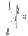
FIG. 4 eosinophils, a subset of leukocytes (white blood cells), depolarise the right angle of scattered light quantified by the above configuration to a greater degree than other leukocytes.FIG. 4 is a graphical representation having the output ofpolarized light detector 14 as one axis and the output of depolarised light detector 16 as the other axis. While the above invention does provide some useful data regarding leukocytes, and more specifically eosinophils, as shown inFIGS. 6B ,7B ,8B and9B , the cluster points within the eosinophil cluster (the cluster points above the angled threshold line on the graphical representation having "DEPOL" as one axis and "ORTHOGONAL" as the other axis) are quite condensed. The dense nature of the points within the eosinophil cluster results in difficulty for the computer software programs that ascertain and identify clusters to accurately identify eosinophil clusters. Additionally, this prior art configuration requires expensive optical devices such as photo multiplier tubes, andlens 6,first polarization analyser 10 andsecond polarization analyser 12. The prior art as indicated in the '497 Patent is unable to distinguish eosinophils without utilizing polarized and depolarized light methods, because the cone of light collected is 72° or less, based on the numerical aperture of the light collection lens, and more practically 50°, based on the number of optical elements that are used. These optical elements, such asbeam splitter 8,polarization analyzers light detectors 14 and 16, contribute to reducing the effective light collection of the system to substantially less than 72°, and to more practically, 50°. - Copending
US Patent Application No. 09/507,515 US Pat. No. 6,320,656 , discloses a device and method for distinguishing eosinophils in a sample of blood cells. The device uses a right angle scatter light detector that is effective to collect a cone of unfiltered right angle scattered light of at least 100° and convert the collected right angle scattered light into a right angle scattered light signal. This signal is processed by the device to distinguish eosinophils from other leukocytes in the sample on the basis of the right angle scattered light signal. - While the device described in the '515 application is capable of detecting eosinophils using unfiltered right angle scattered light, its properties create problems for the economical production of the device. Mechanically, providing a solid mounting scheme to keep right
angle scatter detector 22 in place at a very small distance to flowcell 18 is difficult to design, and more difficult to manufacture. Also, minimizing the distance fromright angle detector 22 topreamplifier 26 is essential to eliminate electrical noise that would otherwise be picked up by the leads of the rightangle photo detector 22. -
WO 00/49387 US Patent No. 4,284,412 discloses a flow cytometer in which a sample is illuminated, a cell at a time, by a focused coherent light and forward light scatter, right angle light scatter, axial loss and fluorescence are detected and used to identify and enumerate cells of a specified subclass. - A need thus exists for a flow cytometer apparatus and related method in which the cell cluster points are less dense for ease of characterization of the different cell clusters. A need also exists for the above apparatus and method which has fewer and less expensive components, and which is easy and economical to manufacture.
- According to a first aspect of the present invention, a high numerical aperture flow cytometer is provided, comprising: a flow cell; a laser input, operable to emit a beam of light that is oriented substantially orthogonally to a direction of flow of blood cells through said flow cell; a right angle scatter light detector, located at a distance of about 2 mm from said flow cell and effective to collect a cone of right angle scattered light of at least 130° and convert it into a right angle scattered light signal; and a signal processor to distinguish eosinophils from other leukocytes on the basis of said right angle scattered light signal; characterised in that the cytometer further comprises: a first forward scatter light detector to collect forward scattered light at an angle between about 1° and about 3° from said beam; a second forward scatter light detector to collect forward scattered light at an angle between about 9° and about 12°; and an axial light loss detector.
- The lens-less light collection flow cytometer of the present invention includes a flow cell and a laser input. The laser input emits a beam of light that is oriented substantially orthogonally to the flow of blood cells through the flow cell such that laser light impinges upon the blood cells as they pass through the flow cell. Unlike the prior art, the laser light emitted by the laser input need not be polarized for analysis of the cells according to the present invention. A portion of the beam from the laser input that impinges upon the blood cells in the flow cell is scattered at a substantially right angle to the beam of laser input ("right angle scatter light"). A second portion of the beam from the laser input that impinges upon the cells in the flow cell is scattered at a much lower angle than 90°. This scatter is termed "forward scatter light" and is collected on two distinct photo detectors. The first detector represents 'forward scatter low' (FSL), i.e., forward scatter light which has an angle of from about 1° to about 3° relative to the laser beam input. A second detector represents 'forward scatter high' (FSH), i.e., forward scatter light which has an angle of from about 9° to about 12° relative to the laser beam input. A third photo detector, axial with the impinging laser light, is placed in between these two forward scatter detectors. This detector measures axial light loss, or light extinction (EXT), which is the sum of all the light that is absorbed and scattered by the blood cells. A right angle scatter light detector is oriented to receive the previously mentioned right angle scatter light. The right angle scatter light detector is located about 2 millimeters from the blood cells in the flow cell. An important aspect of the present invention is that, at the distance of about 2 millimeters from the blood cells, the right angle scatter light detector collects a cone of scattered light of at least 130° or greater. It is this larger light cone value over the prior art light cone of about 50° in practice, and no greater then 72° in theory, that results in the greater cluster separation in the present invention due to the larger signal gathered. In contrast, the smaller 50° cone of the prior art results in missed signals and lesser cluster separation.
- The maximum 72° cone of the prior art is mathematically limited to the numerical aperture of the initial
light collection lens 6. The numerical aperture for the prior art total optical system shown inFig. 1 is much lower, because each optical element reduces the numerical aperture of the total optical system. In contrast, the apparent numerical aperture of a lensless light detection system is equal to the numerical aperture of the total optical system. When a lens less optical system is employed, a ~72° cone angle produces cluster separations that are not apparent in the prior art. Thus, a lens less light collection system may be used in a flow cytometer, which has a much lower numerical aperture, but maintains cluster separation of eosinophils. The advantage of this device is that a lower numerical aperture system can be produced more efficiently and more reproducibly than the prior art devices, because there is more working distance to place components so that the photodetector is held at the proper distance from the flow cell. Additionally, this extra working distance allows for the detector to be mounted on a printed circuit board, which reduces electronic noise, improving the overall signal-to-noise ratio of the optoelectrical system. - A forward light detector array is oriented to capture the previously mentioned forward scatter low, forward scatter high, and axial light, from the beam of the laser input.
- According to a second aspect of the present invention, a method for particle discrimination by light scattering is provided, comprising the steps of: flowing a fluid containing biological cells through a flow cell; directing a beam of light in a direction that contacts said biological cells in said flow cell and which is substantially orthogonal to a direction of flow of said biological cells through said flow cell; detecting a cone of unfiltered right angle scattered light of at least 1300 by using a right angle scatter light detector located at a distance of about 2 mm from said flow cell, converting said detected unfiltered right angle scattered light into a right angle scattered light signal; and identifying eosinophils present among said biological cells on the basis of said right angle scattered light signal; characterised in that the method further comprises: collecting forward scattered light at an angle between about 1° and and about 3° from said beam of laser light, collecting forward scattered light at an angle between 9° and about 12°, and measuring axial light loss.
- These and other objects and features of the invention will become more fully apparent when the following detailed description of the invention is read in conjunction with the accompanying drawings.
-
Figure 1 is a schematic representation of the electro-optical components of a cytometer disclosed in the prior art, namely inUS Patent No. 5,017,497 ; -
Figure 2 is a schematic representation of the electro-optical components of a cytometer according to the present invention; -
Figure 3 is a block diagram of the electronic processing components of a cytometer according to the present invention; -
Figure 4 is a graphical representation of the separation of eosinophils and other white blood cell components based on light scatter data from the prior art device depicted inFigure 1 ; -
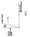
Figure 5 is a graphical representation of the separation of eosinophils and other white blood cell components based on light scatter data from a device according to the present invention; -
Figure 6A is a graphical representation of 2% canine eosinophil data generated using a device according to the present invention; -
Figure 6B is a graphical representation of 2% canine eosinophil data generated using the prior art device; -
Figure 7A is a graphical representation of 8% canine eosinophil data generated using a device according to the present invention; -
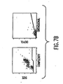
Figure 7B is a graphical representation of 8% canine eosinophil data generated using the prior art device; -
Figure 8A is a graphical representation of 10% canine eosinophil data generated using a device according to the present invention; -
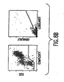
Figure 8B is a graphical representation of 10% canine eosinophil data generated using the prior art device; -
Figure 9A is a graphical representation of human eosinophil data generated using a device according to the present invention; and -
Figure 9B is a graphical representation of human eosinophil data generated using the prior art; -
Figure 10A is a graphical representation of feline eosinophil data obtained using a cone of right angle scattered light at 76°; -
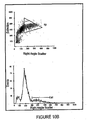
Figure 10B is a graphical representation of feline eosinophil data obtained using a a cone of right angle scattered light at 66°; -
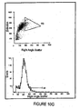
Figure 10C is a graphical representation of feline eosinophil data obtained using a cone of right angle scattered light at 58°; -
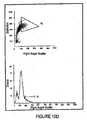
Figure 10D is a graphical representation of feline eosinophil data obtained using a cone of right angle scattered light at 53°; -
Figure 10E is a graphical representation of feline eosinophil data obtained using a cone of right angle scattered light at 46°; -
Figure 10F is a graphical representation of feline eosinophil data obtained using a cone of right angle scattered light at 42°; -
FIG. 10 G is a graphical representation of feline eosinophil data obtained using a cone of right angle scattered light at 42° as inFIG 10 F , but with higher gain to position the mean neutrophil cluster in the same absolute position as inFIG 10 A ; -
FIG. 10 H is a graphically representation of feline eosinophils employing the prior art; and -
FIG. 11 is a schematic illustration of a Mie mask used in a photodetector of a preferred embodiment of the present invention. - Referring to
FIG. 2 , the high numerical aperture flow cytometer of the present invention includes aflow cell 18, which is preferably a quartz flow cell manufactured by Hellma GmbH and Co (Mullheim / Baden, Germany). Preferably flowcell 18 has a flow length of about 1 centimeter and a cross section of 4 millimeter by 4 millimeter. Cells from, for example, blood or the like, flow substantially one by one throughflow cell 18 during analysis.Laser input 20 emits a beam of light that is oriented substantially orthogonally to the flow of blood cells throughflow cell 18 such that laser light impinges upon the blood cells as they pass throughflow cell 18. Unlike the prior art, the laser light emitted bylaser input 20 need not be polarized for analysis of the cells according to the present invention.Laser input 20 maybe for example a 635 nanometer semiconductor diode laser with an output power of 10 milliwatts, model No. HL6320G manufactured by Hitachi and available from Coherent, Inc., Auburn, California. A portion of the beam fromlaser input 20 that impinges upon the blood cells inflow cell 18 is scattered at a substantially right angle to the beam of laser input 20 ("right angle scatter light"). A second portion of the beam fromlaser input 20 that impinges upon the cells inflow cell 18 is scattered at a much lower angle than 90°. This scatter is termed "forward scatter light" and is collected on two distinct photo detectors, one of which represents 'forward scatter low' (FSL) which has an angle of from about 1 ° to about 3°, and the other of which represents 'forward scatter high' (FSH) which has an angle of from about 9° to about 12°, each measured from the orientation of the original laser beam input. A third photo detector is placed between these two forward scatter detectors, that is, axial with the impinging laser light. This detector measures axial light loss, or light extinction (EXT), which is the sum of all the light that is absorbed and scattered by the blood cells. Right anglescatter light detector 22 is oriented to receive the previously mentioned right angle scatter light. Right angle scatter light detector is located about 2 millimeters from the blood cells in theflow cell 18. - Forward scatter
light detector 24 is oriented to capture the previously mentioned axial light loss and forward scatter light, i.e., 'forward scatter low' (FSL) and 'forward scatter high' (FSH). One embodiment oflight detector 24 is shown inFig. 11 , wherecustom detector array 50 is axial withlaser input 20.Custom detector array 50 has three distinct photo detectors, or apertures.Aperture 52 collects axial light loss or extinction,aperture 51 collects forward scatter low, andaperture 53 collects forward scatter high. - To implement a mounting scheme that would allow for a robust detector mount that includes right
angle photo detector 22 and a printed circuit board that representspreamplifier 26, slightly more space was needed betweenflow cell 18 andright angle detector 22. This effectively would cut down the cone of light collection from ~100°, to a lower value. To determine how far fromflow cell 18,detector 22 could be placed,detector 22 was placed on a moveable optical positioning stage, so that it could be moved to various distances fromflow cell 18, and thus changing the cone of light that it could collect. - Indications from the prior art were that values of greater than 72° needed to be achieved to show results that are representative of
Figures 6 through 9 .Figure 10 shows different cone angles of light collection, utilizing the same blood sample. The results of the separation experiments are shown in Table 1. For comparison purposes, the percentage of eosinophils obtained using the device of the '497 patent was 16.0%.Table 1 Figure Cone Angle Eosinophils Separation Quality Eosinophil Percentage 10A 76° Excellent 16.5% 10B 66° Good 15.9% 10C 58° Good 13.7 % 10D 53° Fair 10.5% 10E 46° Poor 3.1 % 10F 42° Poor 2.5 % 10G 42° (high gain) Poor 3.5% - While the electro-optical elements of
FIG. 2 have been described above using specific components, it will readily be apparent to one skilled in the art that different components can be employed to achieve the desired results described above. More specifically, reference is made to Practical Flow Cytometry 3rd Ed. 1995 by Howard M. Shapiro, Wiley-Liss Publisher, ISBN No. 0-471-30376-3 . - Referring to
FIG. 3 , the electrical outputs from right angle scatterlight detector 22 and low angle forward scatterlight detector 24, which may be in voltage or current form, for example, are amplified bypreamplifier 26 and then sent to signalprocessor 28. -
Signal processor 28 measures the area under the voltage or current curve, or measures the peak of the voltage or current curve, received from right anglelight scatter detector 22 and/or low angle forward scatterlight detector 24. The data fromsignal processor 28 is converted by analog todigital converter 30. The digital data is next processed bycentral processing unit 32 based on software programs to display the data in graphical representation ondisplay 34. It will be readily apparent to those skilled in the art that the signal amplification, processing, conversion and display can be accomplished by many well known methods, including but not limited to those disclosed in Practical Flow Cytometry 3rd Ed. by Howard M. Shapiro, 1995 Wiley-Liss Publishers, ISBN No. 0-471-30376-3. - Referring to
FIG. 5 , the output of the data from the flow cytometer of the present invention is shown.FIG. 5 has the output of right angle scatterlight detector 22 as one axis and the output of low angle forward scatterlight detector 24 as the other axis. Eosinophils are located to the right of the software threshold line and, as shown inFIGS. 6A ,7A ,8A , and9A , produce cluster points that are less concentrated than are those of the prior art. Computer software programs employed to identify clusters based on cluster points can thus do so more reliably with the present invention. - B Next referring to
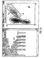
FIGS. 6A ,6B ,7A ,7B ,8A ,8B ,9A and9B , graphical representations of leukocyte identification is shown, with specific reference to eosinophil identification. The data ofFIGS. 6A ,7A ,8A , and9A was employed using the apparatus of the present invention. InFIGS. 6A ,7A ,8A , and9A the term R2 denotes primarily lymphocytes, R3 denotes primarily monocytes, R4 denotes primarily neutrophils and R5 denotes primarily eosinophils.FIGS. 6B ,7B ,8B , and9B pertain to data employing an apparatus substantially disclosed inUS Patent No. 5,017,497 . Whole blood samples of either canine or human blood were prepared as follows before analyzing with the apparatus of present invention or the prior art. The whole blood sample was diluted 10 to 1 in phosphate buffered saline. Then 40 microliters of the phosphate buffered saline treated whole blood sample was mixed with 1,200 microliters of a lysing solution. The lysing solution consisted of 8.3 grams of ammonium chloride, 1 gram of potassium bicarbonate, 0.37 grams tetrasodium EDTA per liter of lysing solution. The whole blood sample was lysed for 20 minutes to one-half of an hour. It will be readily understood by those skilled in the art that lyse time can readily be reduced to between 30 seconds and one minute. - A good correlation exists between the eosinophil of data the present invention of
FIGS. 6A ,7A ,8A and9A with the eosinophil data of the DEPOL/ORTHOGONAL graphical representation of the prior art as shown inFIGS. 6B ,7B ,8B and9B . More specifically, regardingFIGS. 6A and6B , the eosinophil value for the present invention is 2.1% and for the prior art is 2.0%. RegardingFIGS. 7A and7B , the eosinophil data for the present invention is 7.6% and for the prior art is 8.2%. RegardingFIGS. 8A and8B the eosinophil data for the present invention is 13.1% and for the prior art is 9.8%. RegardingFIGS. 9A and9B the eosinophil data for the present invention is 10.8% and for the prior art is 14.6%. For all of the above graphical representations of the present invention,FIGS. 6A ,7A ,8A and9A an eosinophil cluster is present at R5. Regarding the prior art data ofFIGS. 6B ,7B and8B the SIZE/COMPLEXITY graphical representation shows no eosinophil cluster, while the graphical representation ofFIG. 9B does show a cluster. - A comparison of the data of the present invention from
FIGS. 6A ,7A ,8A and9A with the prior art data ofFIGS. 6B ,7B ,8B and9B show a marked decreased density or concentration of the cluster points within the eosinophil clusters. The separation of these cluster points allows the software programs that locate and identify different clusters to more readily locate and identify the clusters produced by the apparatus and method of the present invention compared to those of the prior art. - While the invention has been described with reference to particular embodiments and applications, it will be appreciated that various embodiments and applications based on the teaching of the present invention are possible within the scope of the invention as defined by the appended claims.
Claims (8)
- A high numerical aperture flow cytometer comprising:a flow cell (18);a laser input (20), operable to emit a beam of light that is oriented substantially orthogonally to a direction of flow of blood cells through said flow cell (18);a right angle scatter light detector (22), located at a distance of about 2 mm from said flow cell (18) and effective to collect a cone of right angle scattered light of at least 130° and convert it into a right angle scattered light signal; anda signal processor (28) arranged to distinguish eosinophils from other leukocytes on the basis of said right angle scattered light signal;
characterised in that the cytometer further comprises:a first forward scatter light detector to collect forward scattered light at an angle between about 1° and about 3° from said beam;a second forward scatter light detector to collect forward scattered light at an angle between about 9° and about 12°; andan axial light loss detector. - A high numerical aperture flow cytometer as claimed in claim 1, wherein said flow cell (18) has a flow length of about 1 cm and a cross section of 4 mm by 4 mm.
- A high numerical aperture flow cytometer as claimed in claim 1 or claim 2, wherein said laser input (20) is operable to emit a beam of non-polarised light.
- A high numerical aperture flow cytometer as claimed in any one of the preceding claims, further comprising a preamplifier (26).
- A method for particle discrimination by light scattering comprising the steps of:flowing a fluid containing biological cells through a flow cell (18);directing a beam of light in a direction that contacts said biological cells in said flow cell (18) and which is substantially orthogonal to a direction of flow of said biological cells through said flow cell (18);detecting a cone of unfiltered right angle scattered light of at least 130°, by using a right angle scatter light detector (22) located at a distance of about 2 mm from said flow cell (18);converting said detected unfiltered right angle scattered light into a right angle scattered light signal; andidentifying eosinophils present among said biological cells on the basis of said right angle scattered light signal;
characterised in that the method further comprises:collecting forward scattered light at an angle between about 1° and about 3° from said beam of laser light;collecting forward scattered light at an angle between 9° and about 12°; and measuring axial light loss. - A method as claimed in claim 5, wherein said flowing a fluid consists of flowing a fluid containing biological cells through a flow cell (18) having a flow length of about 1 cm and a cross section of 4 mm by 4 mm.
- A method as claimed in claim 5 or claim 6, wherein said directing a beam of light consists of directing a beam of non-polarised light in a direction that contacts said biological cells in said flow cell (18).
- A method as claimed in any one of claims 5-7, further comprising amplifying the electrical outputs from said right angle scatter light detector (22) and a forward scatter light detector (24) used to collect said forward scattered light, and sending said electrical outputs to a signal processor (28).
Applications Claiming Priority (3)
| Application Number | Priority Date | Filing Date | Title |
|---|---|---|---|
| US969242 | 2001-10-02 | ||
| US09/969,242 US6618143B2 (en) | 2000-02-18 | 2001-10-02 | High numerical aperture flow cytometer and method of using same |
| PCT/US2002/031508 WO2003029787A1 (en) | 2001-10-02 | 2002-10-02 | High numerical aperture flow cytometer and method of using same |
Publications (2)
| Publication Number | Publication Date |
|---|---|
| EP1438564A1 EP1438564A1 (en) | 2004-07-21 |
| EP1438564B1 true EP1438564B1 (en) | 2012-03-21 |
Family
ID=25515344
Family Applications (1)
| Application Number | Title | Priority Date | Filing Date |
|---|---|---|---|
| EP02763835A Expired - Lifetime EP1438564B1 (en) | 2001-10-02 | 2002-10-02 | High numerical aperture flow cytometer and method of using same |
Country Status (7)
| Country | Link |
|---|---|
| US (1) | US6618143B2 (en) |
| EP (1) | EP1438564B1 (en) |
| JP (1) | JP2005504967A (en) |
| AT (1) | ATE550640T1 (en) |
| AU (1) | AU2002327820B2 (en) |
| CA (1) | CA2462734C (en) |
| WO (1) | WO2003029787A1 (en) |
Families Citing this family (92)
| Publication number | Priority date | Publication date | Assignee | Title |
|---|---|---|---|---|
| JP4323571B2 (en) | 1997-01-31 | 2009-09-02 | エックスワイ, インコーポレイテッド | Optical device |
| US6071689A (en) | 1997-12-31 | 2000-06-06 | Xy, Inc. | System for improving yield of sexed embryos in mammals |
| US6149867A (en) | 1997-12-31 | 2000-11-21 | Xy, Inc. | Sheath fluids and collection systems for sex-specific cytometer sorting of sperm |
| ES2296398T3 (en) | 1998-07-30 | 2008-04-16 | Xy, Inc. | NON-SURGICAL ARTIFICIAL EQUINE INSEMINATION SYSTEM. |
| US7208265B1 (en) | 1999-11-24 | 2007-04-24 | Xy, Inc. | Method of cryopreserving selected sperm cells |
| EP2258173A3 (en) | 2000-05-09 | 2012-06-13 | Xy, Llc | High purity x-chromosome bearing and y-chromosome bearing populations of spermatozoa |
| US7277166B2 (en) * | 2000-08-02 | 2007-10-02 | Honeywell International Inc. | Cytometer analysis cartridge optical configuration |
| EP1434522B1 (en) | 2000-10-30 | 2010-01-13 | The General Hospital Corporation | Optical systems for tissue analysis |
| US9295391B1 (en) | 2000-11-10 | 2016-03-29 | The General Hospital Corporation | Spectrally encoded miniature endoscopic imaging probe |
| CA2822983C (en) | 2000-11-29 | 2017-05-09 | Xy, Llc | System to separate frozen-thawed spermatozoa into x-chromosome bearing and y-chromosome bearing populations |
| US7713687B2 (en) | 2000-11-29 | 2010-05-11 | Xy, Inc. | System to separate frozen-thawed spermatozoa into x-chromosome bearing and y-chromosome bearing populations |
| DE10297689B4 (en) * | 2001-05-01 | 2007-10-18 | The General Hospital Corp., Boston | Method and device for the determination of atherosclerotic coating by measurement of optical tissue properties |
| US8211629B2 (en) | 2002-08-01 | 2012-07-03 | Xy, Llc | Low pressure sperm cell separation system |
| US8486618B2 (en) | 2002-08-01 | 2013-07-16 | Xy, Llc | Heterogeneous inseminate system |
| CA2534394C (en) | 2002-08-15 | 2013-01-08 | Xy, Inc. | High resolution flow cytometer |
| US7169548B2 (en) | 2002-09-13 | 2007-01-30 | Xy, Inc. | Sperm cell processing and preservation systems |
| DK2959774T3 (en) | 2003-03-28 | 2019-05-13 | Inguran Llc | PROCEDURE FOR CRYCONSERVATION OF SEAT CELLS |
| AU2004225188B2 (en) | 2003-03-31 | 2010-04-15 | The General Hospital Corporation | Speckle reduction in optical coherence tomography by path length encoded angular compounding |
| WO2004104178A2 (en) | 2003-05-15 | 2004-12-02 | Xy, Inc. | Efficient haploid cell sorting for flow cytometer systems |
| EP2280258A3 (en) | 2003-06-06 | 2015-09-02 | The General Hospital Corporation | Process and apparatus for a wavelength tuned light source |
| CN103293126B (en) | 2003-10-27 | 2017-03-01 | 通用医疗公司 | Method and apparatus for carrying out optical imagery using frequency-domain interferometry |
| EP2260854A1 (en) | 2004-03-29 | 2010-12-15 | Inguran, LLC | Sperm suspensions for sorting into x or y chromosome-bearing enriched populations |
| EP1771755B1 (en) | 2004-07-02 | 2016-09-21 | The General Hospital Corporation | Endoscopic imaging probe comprising dual clad fibre |
| AU2005266930B2 (en) | 2004-07-22 | 2010-09-16 | Inguran, Llc | Process for enriching a population of sperm cells |
| JP5053845B2 (en) | 2004-08-06 | 2012-10-24 | ザ ジェネラル ホスピタル コーポレイション | Method, system and software apparatus for determining at least one position in a sample using optical coherence tomography |
| KR20070058523A (en) | 2004-08-24 | 2007-06-08 | 더 제너럴 하스피탈 코포레이션 | Method and apparatus for imaging of vessel segments |
| EP1793730B1 (en) | 2004-08-24 | 2011-12-28 | The General Hospital Corporation | Process, system and software arrangement for determining elastic modulus |
| US7366376B2 (en) | 2004-09-29 | 2008-04-29 | The General Hospital Corporation | System and method for optical coherence imaging |
| EP1816949A1 (en) | 2004-11-29 | 2007-08-15 | The General Hospital Corporation | Arrangements, devices, endoscopes, catheters and methods for performing optical imaging by simultaneously illuminating and detecting multiple points on a sample |
| WO2006116769A1 (en) | 2005-04-28 | 2006-11-02 | The General Hospital Corporation | Systems, processes and software arrangements for evaluating information associated with an anatomical structure by an optical coherence ranging technique |
| US9060689B2 (en) | 2005-06-01 | 2015-06-23 | The General Hospital Corporation | Apparatus, method and system for performing phase-resolved optical frequency domain imaging |
| US7618770B2 (en) | 2005-07-29 | 2009-11-17 | Xy, Inc. | Methods and apparatus for reducing protein content in sperm cell extenders |
| ATE484727T1 (en) | 2005-08-09 | 2010-10-15 | Gen Hospital Corp | DEVICE AND METHOD FOR PERFORMING POLARIZATION-BASED QUADRATURE DEMODULATION IN OPTICAL COHERENCE TOMOGRAPHY |
| JP6046325B2 (en) | 2005-09-29 | 2016-12-14 | ザ ジェネラル ホスピタル コーポレイション | Method and apparatus for the observation and analysis of one or more biological samples with progressively increased resolution |
| US7299135B2 (en) * | 2005-11-10 | 2007-11-20 | Idexx Laboratories, Inc. | Methods for identifying discrete populations (e.g., clusters) of data within a flow cytometer multi-dimensional data set |
| US8145018B2 (en) | 2006-01-19 | 2012-03-27 | The General Hospital Corporation | Apparatus for obtaining information for a structure using spectrally-encoded endoscopy techniques and methods for producing one or more optical arrangements |
| EP2289396A3 (en) | 2006-01-19 | 2011-04-06 | The General Hospital Corporation | Methods and systems for optical imaging of epithelial luminal organs by beam scanning thereof |
| US7538859B2 (en) | 2006-02-01 | 2009-05-26 | The General Hospital Corporation | Methods and systems for monitoring and obtaining information of at least one portion of a sample using conformal laser therapy procedures, and providing electromagnetic radiation thereto |
| JP5524487B2 (en) | 2006-02-01 | 2014-06-18 | ザ ジェネラル ホスピタル コーポレイション | A method and system for emitting electromagnetic radiation to at least a portion of a sample using a conformal laser treatment procedure. |
| EP1987318B1 (en) | 2006-02-24 | 2015-08-12 | The General Hospital Corporation | Methods and systems for performing angle-resolved fourier-domain optical coherence tomography |
| WO2007133961A2 (en) | 2006-05-10 | 2007-11-22 | The General Hospital Corporation | Processes, arrangements and systems for providing frequency domain imaging of a sample |
| WO2008049118A2 (en) | 2006-10-19 | 2008-04-24 | The General Hospital Corporation | Apparatus and method for obtaining and providing imaging information associated with at least one portion of a sample and effecting such portion(s) |
| US7804594B2 (en) * | 2006-12-29 | 2010-09-28 | Abbott Laboratories, Inc. | Method and apparatus for rapidly counting and identifying biological particles in a flow stream |
| EP4151985B1 (en) | 2007-02-01 | 2026-05-20 | Sysmex Corp | SAMPLE ANALYSIS INSTRUMENT AND THE PROCEDURES CARRIED OUT BY A SAMPLE ANALYSIS INSTRUMENT |
| EP2602651A3 (en) | 2007-03-23 | 2014-08-27 | The General Hospital Corporation | Methods, arrangements and apparatus for utilizing a wavelength-swept laser using angular scanning and dispersion procedures |
| WO2008121844A1 (en) | 2007-03-30 | 2008-10-09 | The General Hospital Corporation | System and method providing intracoronary laser speckle imaging for the detection of vulnerable plaque |
| CL2008002118A1 (en) * | 2007-07-19 | 2008-12-19 | Xy Llc | Method for the production of an equine embryo of selected sex by intracytoplasmic sperm injection using equine sperm selected by sex. |
| US8159670B2 (en) | 2007-11-05 | 2012-04-17 | Abbott Laboratories | Method and apparatus for rapidly counting and identifying biological particles in a flow stream |
| WO2009137701A2 (en) | 2008-05-07 | 2009-11-12 | The General Hospital Corporation | System, method and computer-accessible medium for tracking vessel motion during three-dimensional coronary artery microscopy |
| US8861910B2 (en) | 2008-06-20 | 2014-10-14 | The General Hospital Corporation | Fused fiber optic coupler arrangement and method for use thereof |
| WO2010009136A2 (en) | 2008-07-14 | 2010-01-21 | The General Hospital Corporation | Apparatus and methods for color endoscopy |
| US8937724B2 (en) | 2008-12-10 | 2015-01-20 | The General Hospital Corporation | Systems and methods for extending imaging depth range of optical coherence tomography through optical sub-sampling |
| US9615748B2 (en) | 2009-01-20 | 2017-04-11 | The General Hospital Corporation | Endoscopic biopsy apparatus, system and method |
| JP6053284B2 (en) | 2009-02-04 | 2016-12-27 | ザ ジェネラル ホスピタル コーポレイション | Apparatus and method for use of a high speed optical wavelength tuning source |
| EP2425241A4 (en) * | 2009-04-27 | 2015-05-13 | Abbott Lab | Method for discriminating red blood cells from white blood cells by using forward scattering from a laser in an automated hematology analyzer |
| WO2011008822A2 (en) | 2009-07-14 | 2011-01-20 | The General Hospital Corporation | Apparatus, systems and methods for measuring flow and pressure within a vessel |
| EP2485641A4 (en) * | 2009-10-06 | 2015-10-14 | Gen Hospital Corp | APPARATUS AND METHODS FOR IMAGING PARTICULAR CELLS INCLUDING EOSINOPHILES |
| US20110129864A1 (en) * | 2009-12-02 | 2011-06-02 | Idexx Laboratories, Inc. | Method for analyzing lymph node aspirate using multi-angle light scatter flow cytometer |
| KR20130004326A (en) | 2010-03-05 | 2013-01-09 | 더 제너럴 하스피탈 코포레이션 | Systems, methods and computer-accessible medium which provide microscopic images of at least one anatomical structure at a particular resolution |
| US9069130B2 (en) | 2010-05-03 | 2015-06-30 | The General Hospital Corporation | Apparatus, method and system for generating optical radiation from biological gain media |
| US9097704B2 (en) | 2010-05-05 | 2015-08-04 | Abbott Laboratories | Method for hematology analysis |
| US9795301B2 (en) | 2010-05-25 | 2017-10-24 | The General Hospital Corporation | Apparatus, systems, methods and computer-accessible medium for spectral analysis of optical coherence tomography images |
| WO2011149972A2 (en) | 2010-05-25 | 2011-12-01 | The General Hospital Corporation | Systems, devices, methods, apparatus and computer-accessible media for providing optical imaging of structures and compositions |
| US10285568B2 (en) | 2010-06-03 | 2019-05-14 | The General Hospital Corporation | Apparatus and method for devices for imaging structures in or at one or more luminal organs |
| JP5883018B2 (en) | 2010-10-27 | 2016-03-09 | ザ ジェネラル ホスピタル コーポレイション | Apparatus, system, and method for measuring blood pressure within at least one blood vessel |
| WO2013013049A1 (en) | 2011-07-19 | 2013-01-24 | The General Hospital Corporation | Systems, methods, apparatus and computer-accessible-medium for providing polarization-mode dispersion compensation in optical coherence tomography |
| EP2748587B1 (en) | 2011-08-25 | 2021-01-13 | The General Hospital Corporation | Methods and arrangements for providing micro-optical coherence tomography procedures |
| WO2013066631A1 (en) | 2011-10-18 | 2013-05-10 | The General Hospital Corporation | Apparatus and methods for producing and/or providing recirculating optical delay(s) |
| WO2013148306A1 (en) | 2012-03-30 | 2013-10-03 | The General Hospital Corporation | Imaging system, method and distal attachment for multidirectional field of view endoscopy |
| US11490797B2 (en) | 2012-05-21 | 2022-11-08 | The General Hospital Corporation | Apparatus, device and method for capsule microscopy |
| US9746412B2 (en) | 2012-05-30 | 2017-08-29 | Iris International, Inc. | Flow cytometer |
| EP2888616A4 (en) | 2012-08-22 | 2016-04-27 | Gen Hospital Corp | SYSTEM, METHOD AND COMPUTER-ACCESSIBLE MEDIA FOR MANUFACTURING MINIATURE ENDOSCOPES USING SOFT LITHOGRAPHY |
| JP6560126B2 (en) | 2013-01-28 | 2019-08-14 | ザ ジェネラル ホスピタル コーポレイション | Apparatus and method for providing diffusion spectroscopy superimposed on optical frequency domain imaging |
| WO2014120791A1 (en) | 2013-01-29 | 2014-08-07 | The General Hospital Corporation | Apparatus, systems and methods for providing information regarding the aortic valve |
| US11179028B2 (en) | 2013-02-01 | 2021-11-23 | The General Hospital Corporation | Objective lens arrangement for confocal endomicroscopy |
| US10478072B2 (en) | 2013-03-15 | 2019-11-19 | The General Hospital Corporation | Methods and system for characterizing an object |
| US9784681B2 (en) | 2013-05-13 | 2017-10-10 | The General Hospital Corporation | System and method for efficient detection of the phase and amplitude of a periodic modulation associated with self-interfering fluorescence |
| US11452433B2 (en) | 2013-07-19 | 2022-09-27 | The General Hospital Corporation | Imaging apparatus and method which utilizes multidirectional field of view endoscopy |
| WO2015010133A1 (en) | 2013-07-19 | 2015-01-22 | The General Hospital Corporation | Determining eye motion by imaging retina. with feedback |
| US9668652B2 (en) | 2013-07-26 | 2017-06-06 | The General Hospital Corporation | System, apparatus and method for utilizing optical dispersion for fourier-domain optical coherence tomography |
| US9733460B2 (en) | 2014-01-08 | 2017-08-15 | The General Hospital Corporation | Method and apparatus for microscopic imaging |
| US10736494B2 (en) | 2014-01-31 | 2020-08-11 | The General Hospital Corporation | System and method for facilitating manual and/or automatic volumetric imaging with real-time tension or force feedback using a tethered imaging device |
| WO2015153982A1 (en) | 2014-04-04 | 2015-10-08 | The General Hospital Corporation | Apparatus and method for controlling propagation and/or transmission of electromagnetic radiation in flexible waveguide(s) |
| CN104020085B (en) * | 2014-06-17 | 2016-07-06 | 大连理工大学 | A Method for Optical Detection and Microscopic Imaging of Micro-Nano Particles Unaffected by Background |
| ES2907287T3 (en) | 2014-07-25 | 2022-04-22 | Massachusetts Gen Hospital | Apparatus for imaging and in vivo diagnosis |
| US10151682B2 (en) * | 2015-07-14 | 2018-12-11 | Teilch Llc | Airborne particle measuring device |
| US10215683B2 (en) | 2015-11-02 | 2019-02-26 | Chiranjit Deka | Light scatter based apparatus and methods for hematology analysis using only three detectors |
| CN115917292B (en) | 2020-06-17 | 2023-08-25 | Idexx实验室公司 | Flow cytometer and laser optical component thereof |
| WO2023158803A1 (en) | 2022-02-18 | 2023-08-24 | Idexx Laboratories Inc. | Flow cytometry systems and methods for presenting two‑dimensional dot plot |
| WO2024102641A1 (en) | 2022-11-07 | 2024-05-16 | Idexx Laboratories Inc. | Systems and methods for identifying blood conditions via dot plot analysis |
| CN116242776B (en) * | 2023-02-24 | 2025-09-23 | 深圳市科曼医疗设备有限公司 | Optical calibration method, device, equipment and medium |
| US12584902B2 (en) | 2023-12-10 | 2026-03-24 | Instrumentation Laboratory Company | Acoustic separation of a test sample |
Family Cites Families (19)
| Publication number | Priority date | Publication date | Assignee | Title |
|---|---|---|---|---|
| US4284412A (en) | 1979-07-13 | 1981-08-18 | Ortho Diagnostics, Inc. | Method and apparatus for automated identification and enumeration of specified blood cell subclasses |
| US4818103A (en) * | 1981-05-15 | 1989-04-04 | Ratcom | Flow cytometry |
| US4565448A (en) * | 1983-03-11 | 1986-01-21 | E. I. Du Pont De Nemours And Company | Particle counting apparatus |
| US4606636A (en) * | 1983-10-25 | 1986-08-19 | Universite De Saint-Etienne | Optical apparatus for identifying the individual multiparametric properties of particles or bodies in a continuous flow |
| NL8601000A (en) * | 1986-04-21 | 1987-11-16 | Jan Greve T H Twente Afdeling | THE USE OF POLARIZED LIGHT IN FLOW CYTOMETRY. |
| US5179026A (en) * | 1986-11-27 | 1993-01-12 | Toa Medical Electronics Co., Ltd. | Method of classifying leukocytes by flow cytometry and reagents used in the method |
| US5408307A (en) * | 1988-07-11 | 1995-04-18 | Omron Tateisi Electronics Co. | Cell analyzer |
| US4954715A (en) * | 1989-06-26 | 1990-09-04 | Zoeld Tibor | Method and apparatus for an optimized multiparameter flow-through particle and cell analyzer |
| JP3067849B2 (en) * | 1991-07-29 | 2000-07-24 | シスメックス株式会社 | Sample preparation method for leukocyte classification and counting |
| JP3048260B2 (en) * | 1991-07-29 | 2000-06-05 | シスメックス株式会社 | Sample preparation method for leukocyte classification and counting |
| JP2804873B2 (en) * | 1992-12-17 | 1998-09-30 | 三菱電機株式会社 | Particle analysis device and particle analysis method |
| US5467189A (en) * | 1993-01-22 | 1995-11-14 | Venturedyne, Ltd. | Improved particle sensor and method for assaying a particle |
| US5631165A (en) * | 1994-08-01 | 1997-05-20 | Abbott Laboratories | Method for performing automated hematology and cytometry analysis |
| JP3324050B2 (en) * | 1994-10-31 | 2002-09-17 | 日本光電工業株式会社 | Leukocyte classification reagent and leukocyte classification method |
| US5650847A (en) * | 1995-06-14 | 1997-07-22 | Erkki Soini | Method and device for determination of parameters of individual microparticles |
| DE19700648A1 (en) * | 1997-01-10 | 1998-07-23 | Basf Ag | Method and device for determining the size distribution of different types of particles in a sample |
| JP2002537557A (en) | 1999-02-19 | 2002-11-05 | アイデックス ラボラトリーズ インコーポレイテッド | High numerical aperture flow cytometer and method of using same |
| US6320656B1 (en) * | 2000-02-18 | 2001-11-20 | Idexx Laboratories, Inc. | High numerical aperture flow cytometer and method of using same |
| US6784981B1 (en) | 2000-06-02 | 2004-08-31 | Idexx Laboratories, Inc. | Flow cytometry-based hematology system |
-
2001
- 2001-10-02 US US09/969,242 patent/US6618143B2/en not_active Expired - Lifetime
-
2002
- 2002-10-02 JP JP2003532950A patent/JP2005504967A/en active Pending
- 2002-10-02 EP EP02763835A patent/EP1438564B1/en not_active Expired - Lifetime
- 2002-10-02 AT AT02763835T patent/ATE550640T1/en active
- 2002-10-02 WO PCT/US2002/031508 patent/WO2003029787A1/en not_active Ceased
- 2002-10-02 AU AU2002327820A patent/AU2002327820B2/en not_active Expired
- 2002-10-02 CA CA2462734A patent/CA2462734C/en not_active Expired - Lifetime
Also Published As
| Publication number | Publication date |
|---|---|
| CA2462734C (en) | 2012-01-03 |
| AU2002327820B2 (en) | 2007-12-20 |
| JP2005504967A (en) | 2005-02-17 |
| ATE550640T1 (en) | 2012-04-15 |
| EP1438564A1 (en) | 2004-07-21 |
| CA2462734A1 (en) | 2003-04-10 |
| US6618143B2 (en) | 2003-09-09 |
| WO2003029787A1 (en) | 2003-04-10 |
| US20020113965A1 (en) | 2002-08-22 |
Similar Documents
| Publication | Publication Date | Title |
|---|---|---|
| CA2462734C (en) | High numerical aperture flow cytometer and method of using same | |
| AU2002327820A1 (en) | High numerical aperture flow cytometer and method of using same | |
| US6320656B1 (en) | High numerical aperture flow cytometer and method of using same | |
| JP2505873B2 (en) | Particle analyzer with scattered light | |
| US9494509B2 (en) | System and method for measuring particles in a sample stream of a flow cytometer using low-power laser source | |
| JP3375203B2 (en) | Cell analyzer | |
| US4798465A (en) | Particle size detection device having high sensitivity in high molecular scattering environment | |
| US20070105231A1 (en) | Method and apparatus for performing platelet measurement | |
| EP0698211A1 (en) | Reticulocyte analyzing method and apparatus utilizing light scatter techniques | |
| JPH0129576Y2 (en) | ||
| AU768616C (en) | High numerical aperture flow cytometer and method of using same | |
| JP3504029B2 (en) | Particle analyzer | |
| JP3504030B2 (en) | Method and apparatus for determining particle criterion, and particle analyzer using the criterion | |
| Burger et al. | Acousto‐optic laser‐scanning cytometer | |
| JPS6193932A (en) | particle analyzer | |
| GB2265217A (en) | Apparatus for detecting fibrous particles | |
| JPS62108386A (en) | Particulate counter |
Legal Events
| Date | Code | Title | Description |
|---|---|---|---|
| PUAI | Public reference made under article 153(3) epc to a published international application that has entered the european phase |
Free format text: ORIGINAL CODE: 0009012 |
|
| 17P | Request for examination filed |
Effective date: 20040423 |
|
| AK | Designated contracting states |
Kind code of ref document: A1 Designated state(s): AT BE BG CH CY CZ DE DK EE ES FI FR GB GR IE IT LI LU MC NL PT SE SK TR |
|
| AX | Request for extension of the european patent |
Extension state: AL LT LV MK RO SI |
|
| 17Q | First examination report despatched |
Effective date: 20090303 |
|
| GRAP | Despatch of communication of intention to grant a patent |
Free format text: ORIGINAL CODE: EPIDOSNIGR1 |
|
| GRAS | Grant fee paid |
Free format text: ORIGINAL CODE: EPIDOSNIGR3 |
|
| GRAA | (expected) grant |
Free format text: ORIGINAL CODE: 0009210 |
|
| AK | Designated contracting states |
Kind code of ref document: B1 Designated state(s): AT BE BG CH CY CZ DE DK EE ES FI FR GB GR IE IT LI LU MC NL PT SE SK TR |
|
| REG | Reference to a national code |
Ref country code: GB Ref legal event code: FG4D |
|
| REG | Reference to a national code |
Ref country code: CH Ref legal event code: EP |
|
| REG | Reference to a national code |
Ref country code: IE Ref legal event code: FG4D |
|
| REG | Reference to a national code |
Ref country code: AT Ref legal event code: REF Ref document number: 550640 Country of ref document: AT Kind code of ref document: T Effective date: 20120415 |
|
| REG | Reference to a national code |
Ref country code: DE Ref legal event code: R096 Ref document number: 60242466 Country of ref document: DE Effective date: 20120516 |
|
| REG | Reference to a national code |
Ref country code: NL Ref legal event code: VDEP Effective date: 20120321 |
|
| PG25 | Lapsed in a contracting state [announced via postgrant information from national office to epo] |
Ref country code: GR Free format text: LAPSE BECAUSE OF FAILURE TO SUBMIT A TRANSLATION OF THE DESCRIPTION OR TO PAY THE FEE WITHIN THE PRESCRIBED TIME-LIMIT Effective date: 20120622 Ref country code: FI Free format text: LAPSE BECAUSE OF FAILURE TO SUBMIT A TRANSLATION OF THE DESCRIPTION OR TO PAY THE FEE WITHIN THE PRESCRIBED TIME-LIMIT Effective date: 20120321 |
|
| REG | Reference to a national code |
Ref country code: AT Ref legal event code: MK05 Ref document number: 550640 Country of ref document: AT Kind code of ref document: T Effective date: 20120321 |
|
| PG25 | Lapsed in a contracting state [announced via postgrant information from national office to epo] |
Ref country code: CY Free format text: LAPSE BECAUSE OF FAILURE TO SUBMIT A TRANSLATION OF THE DESCRIPTION OR TO PAY THE FEE WITHIN THE PRESCRIBED TIME-LIMIT Effective date: 20120321 |
|
| PG25 | Lapsed in a contracting state [announced via postgrant information from national office to epo] |
Ref country code: CZ Free format text: LAPSE BECAUSE OF FAILURE TO SUBMIT A TRANSLATION OF THE DESCRIPTION OR TO PAY THE FEE WITHIN THE PRESCRIBED TIME-LIMIT Effective date: 20120321 Ref country code: BE Free format text: LAPSE BECAUSE OF FAILURE TO SUBMIT A TRANSLATION OF THE DESCRIPTION OR TO PAY THE FEE WITHIN THE PRESCRIBED TIME-LIMIT Effective date: 20120321 Ref country code: SE Free format text: LAPSE BECAUSE OF FAILURE TO SUBMIT A TRANSLATION OF THE DESCRIPTION OR TO PAY THE FEE WITHIN THE PRESCRIBED TIME-LIMIT Effective date: 20120321 Ref country code: EE Free format text: LAPSE BECAUSE OF FAILURE TO SUBMIT A TRANSLATION OF THE DESCRIPTION OR TO PAY THE FEE WITHIN THE PRESCRIBED TIME-LIMIT Effective date: 20120321 |
|
| PG25 | Lapsed in a contracting state [announced via postgrant information from national office to epo] |
Ref country code: SK Free format text: LAPSE BECAUSE OF FAILURE TO SUBMIT A TRANSLATION OF THE DESCRIPTION OR TO PAY THE FEE WITHIN THE PRESCRIBED TIME-LIMIT Effective date: 20120321 Ref country code: PT Free format text: LAPSE BECAUSE OF FAILURE TO SUBMIT A TRANSLATION OF THE DESCRIPTION OR TO PAY THE FEE WITHIN THE PRESCRIBED TIME-LIMIT Effective date: 20120723 |
|
| PLBE | No opposition filed within time limit |
Free format text: ORIGINAL CODE: 0009261 |
|
| STAA | Information on the status of an ep patent application or granted ep patent |
Free format text: STATUS: NO OPPOSITION FILED WITHIN TIME LIMIT |
|
| PG25 | Lapsed in a contracting state [announced via postgrant information from national office to epo] |
Ref country code: NL Free format text: LAPSE BECAUSE OF FAILURE TO SUBMIT A TRANSLATION OF THE DESCRIPTION OR TO PAY THE FEE WITHIN THE PRESCRIBED TIME-LIMIT Effective date: 20120321 Ref country code: DK Free format text: LAPSE BECAUSE OF FAILURE TO SUBMIT A TRANSLATION OF THE DESCRIPTION OR TO PAY THE FEE WITHIN THE PRESCRIBED TIME-LIMIT Effective date: 20120321 Ref country code: AT Free format text: LAPSE BECAUSE OF FAILURE TO SUBMIT A TRANSLATION OF THE DESCRIPTION OR TO PAY THE FEE WITHIN THE PRESCRIBED TIME-LIMIT Effective date: 20120321 |
|
| 26N | No opposition filed |
Effective date: 20130102 |
|
| PG25 | Lapsed in a contracting state [announced via postgrant information from national office to epo] |
Ref country code: IT Free format text: LAPSE BECAUSE OF FAILURE TO SUBMIT A TRANSLATION OF THE DESCRIPTION OR TO PAY THE FEE WITHIN THE PRESCRIBED TIME-LIMIT Effective date: 20120321 |
|
| REG | Reference to a national code |
Ref country code: DE Ref legal event code: R097 Ref document number: 60242466 Country of ref document: DE Effective date: 20130102 |
|
| PG25 | Lapsed in a contracting state [announced via postgrant information from national office to epo] |
Ref country code: ES Free format text: LAPSE BECAUSE OF FAILURE TO SUBMIT A TRANSLATION OF THE DESCRIPTION OR TO PAY THE FEE WITHIN THE PRESCRIBED TIME-LIMIT Effective date: 20120702 |
|
| PG25 | Lapsed in a contracting state [announced via postgrant information from national office to epo] |
Ref country code: MC Free format text: LAPSE BECAUSE OF NON-PAYMENT OF DUE FEES Effective date: 20121031 |
|
| REG | Reference to a national code |
Ref country code: CH Ref legal event code: PL |
|
| REG | Reference to a national code |
Ref country code: IE Ref legal event code: MM4A |
|
| PG25 | Lapsed in a contracting state [announced via postgrant information from national office to epo] |
Ref country code: BG Free format text: LAPSE BECAUSE OF FAILURE TO SUBMIT A TRANSLATION OF THE DESCRIPTION OR TO PAY THE FEE WITHIN THE PRESCRIBED TIME-LIMIT Effective date: 20120621 Ref country code: LI Free format text: LAPSE BECAUSE OF NON-PAYMENT OF DUE FEES Effective date: 20121031 Ref country code: IE Free format text: LAPSE BECAUSE OF NON-PAYMENT OF DUE FEES Effective date: 20121002 Ref country code: CH Free format text: LAPSE BECAUSE OF NON-PAYMENT OF DUE FEES Effective date: 20121031 |
|
| PG25 | Lapsed in a contracting state [announced via postgrant information from national office to epo] |
Ref country code: TR Free format text: LAPSE BECAUSE OF FAILURE TO SUBMIT A TRANSLATION OF THE DESCRIPTION OR TO PAY THE FEE WITHIN THE PRESCRIBED TIME-LIMIT Effective date: 20120321 |
|
| PG25 | Lapsed in a contracting state [announced via postgrant information from national office to epo] |
Ref country code: LU Free format text: LAPSE BECAUSE OF NON-PAYMENT OF DUE FEES Effective date: 20121002 |
|
| REG | Reference to a national code |
Ref country code: FR Ref legal event code: PLFP Year of fee payment: 14 |
|
| REG | Reference to a national code |
Ref country code: FR Ref legal event code: PLFP Year of fee payment: 15 |
|
| REG | Reference to a national code |
Ref country code: FR Ref legal event code: PLFP Year of fee payment: 16 |
|
| REG | Reference to a national code |
Ref country code: FR Ref legal event code: PLFP Year of fee payment: 17 |
|
| PGFP | Annual fee paid to national office [announced via postgrant information from national office to epo] |
Ref country code: DE Payment date: 20211027 Year of fee payment: 20 Ref country code: GB Payment date: 20211027 Year of fee payment: 20 |
|
| PGFP | Annual fee paid to national office [announced via postgrant information from national office to epo] |
Ref country code: FR Payment date: 20211025 Year of fee payment: 20 |
|
| REG | Reference to a national code |
Ref country code: DE Ref legal event code: R071 Ref document number: 60242466 Country of ref document: DE |
|
| REG | Reference to a national code |
Ref country code: GB Ref legal event code: PE20 Expiry date: 20221001 |
|
| PG25 | Lapsed in a contracting state [announced via postgrant information from national office to epo] |
Ref country code: GB Free format text: LAPSE BECAUSE OF EXPIRATION OF PROTECTION Effective date: 20221001 |