EP1438473B1 - Pressure sensing dead bolt - Google Patents
Pressure sensing dead bolt Download PDFInfo
- Publication number
- EP1438473B1 EP1438473B1 EP20020778455 EP02778455A EP1438473B1 EP 1438473 B1 EP1438473 B1 EP 1438473B1 EP 20020778455 EP20020778455 EP 20020778455 EP 02778455 A EP02778455 A EP 02778455A EP 1438473 B1 EP1438473 B1 EP 1438473B1
- Authority
- EP
- European Patent Office
- Prior art keywords
- panel
- dead bolt
- pressure
- frame
- latching
- Prior art date
- Legal status (The legal status is an assumption and is not a legal conclusion. Google has not performed a legal analysis and makes no representation as to the accuracy of the status listed.)
- Expired - Lifetime
Links
Images





Classifications
-
- B—PERFORMING OPERATIONS; TRANSPORTING
- B64—AIRCRAFT; AVIATION; COSMONAUTICS
- B64C—AEROPLANES; HELICOPTERS
- B64C1/00—Fuselages; Constructional features common to fuselages, wings, stabilising surfaces or the like
- B64C1/14—Windows; Doors; Hatch covers or access panels; Surrounding frame structures; Canopies; Windscreens accessories therefor, e.g. pressure sensors, water deflectors, hinges, seals, handles, latches, windscreen wipers
- B64C1/1407—Doors; surrounding frames
- B64C1/1469—Doors between cockpit and cabin
-
- B—PERFORMING OPERATIONS; TRANSPORTING
- B64—AIRCRAFT; AVIATION; COSMONAUTICS
- B64D—EQUIPMENT FOR FITTING IN OR TO AIRCRAFT; FLIGHT SUITS; PARACHUTES; ARRANGEMENT OR MOUNTING OF POWER PLANTS OR PROPULSION TRANSMISSIONS IN AIRCRAFT
- B64D45/00—Aircraft indicators or protectors not otherwise provided for
- B64D45/0015—Devices specially adapted for the protection against criminal attack, e.g. anti-hijacking systems
- B64D45/0021—Devices specially adapted for the protection against criminal attack, e.g. anti-hijacking systems means for restricting access to flight deck
- B64D45/0028—Devices specially adapted for the protection against criminal attack, e.g. anti-hijacking systems means for restricting access to flight deck doors or door arrangements specially adapted to restrict unauthorized access
-
- E—FIXED CONSTRUCTIONS
- E05—LOCKS; KEYS; WINDOW OR DOOR FITTINGS; SAFES
- E05B—LOCKS; ACCESSORIES THEREFOR; HANDCUFFS
- E05B51/00—Operating or controlling locks or other fastening devices by other non-mechanical means
- E05B51/02—Operating or controlling locks or other fastening devices by other non-mechanical means by pneumatic or hydraulic means
- E05B51/023—Operating or controlling locks or other fastening devices by other non-mechanical means by pneumatic or hydraulic means actuated in response to external pressure, blast or explosion
-
- B—PERFORMING OPERATIONS; TRANSPORTING
- B64—AIRCRAFT; AVIATION; COSMONAUTICS
- B64C—AEROPLANES; HELICOPTERS
- B64C1/00—Fuselages; Constructional features common to fuselages, wings, stabilising surfaces or the like
- B64C2001/009—Fuselages; Constructional features common to fuselages, wings, stabilising surfaces or the like comprising decompression panels or valves for pressure equalisation in fuselages or floors
-
- Y—GENERAL TAGGING OF NEW TECHNOLOGICAL DEVELOPMENTS; GENERAL TAGGING OF CROSS-SECTIONAL TECHNOLOGIES SPANNING OVER SEVERAL SECTIONS OF THE IPC; TECHNICAL SUBJECTS COVERED BY FORMER USPC CROSS-REFERENCE ART COLLECTIONS [XRACs] AND DIGESTS
- Y10—TECHNICAL SUBJECTS COVERED BY FORMER USPC
- Y10T—TECHNICAL SUBJECTS COVERED BY FORMER US CLASSIFICATION
- Y10T292/00—Closure fasteners
- Y10T292/08—Bolts
- Y10T292/1043—Swinging
- Y10T292/1051—Spring projected
- Y10T292/1052—Operating means
- Y10T292/106—Push or pull rod
-
- Y—GENERAL TAGGING OF NEW TECHNOLOGICAL DEVELOPMENTS; GENERAL TAGGING OF CROSS-SECTIONAL TECHNOLOGIES SPANNING OVER SEVERAL SECTIONS OF THE IPC; TECHNICAL SUBJECTS COVERED BY FORMER USPC CROSS-REFERENCE ART COLLECTIONS [XRACs] AND DIGESTS
- Y10—TECHNICAL SUBJECTS COVERED BY FORMER USPC
- Y10T—TECHNICAL SUBJECTS COVERED BY FORMER US CLASSIFICATION
- Y10T292/00—Closure fasteners
- Y10T292/08—Bolts
- Y10T292/1043—Swinging
- Y10T292/1075—Operating means
- Y10T292/1082—Motor
Definitions
- the present disclosure relates to a method, system and apparatus for a latching device which operates in response to a pressure differential between a first side and a second side of a barrier to allow a panel associated with the barrier to release upon a given set or range of pressure conditions.
- a variety of latching systems have been developed to maintain doors and other structures in a closed position.
- the reference to panels, doors and other structures relates to the use of latching devices to retain a first body such as a panel relative to a second body, such as a frame.
- a panel includes one portion which might be rotatably hinged or otherwise movably retained on a corresponding structure such as a frame.
- the panel serves to close or cover at least a portion of an opening defined by the frame for a variety of purposes including providing a barrier to prevent passage through the opening.
- Document WO8401404 describes a dead bolt latching device according to the preamble of claim 1.
- blowout latching devices have been developed to facilitate the movement or "blowout” of a panel relative to the frame.
- blowout latching devices have been developed by Hartwell Corporation, assignee of the present disclosure to facilitate disengagement of a panel from a frame or other structure under a set or range of "blowout” conditions. For example, if pressure builds up within an area at least partially housed or contained by the panel, the pressure differential will rise to a point where the panel may be forcibly removed, disengaged or "blown out” from the frame by force associated with the pressure differential. Under these conditions, it is desirable to set the blowout force at a level or range so that premature disengagement of the panel from the primary structure does not occur. In this situation, the blow out load level can be set so that a predetermined pressure differential disengages the panel from the primary structure to protect and preserve the integrity of the frame and any related structures and devices.
- a door in a closed position under one level or range of pressure conditions yet release the door under a second range or set of conditions.
- Such level or range may or may not overlap or may be discrete ranges or, in fact, points.
- the panel in such a situation generally is in an environment where the pressure on either side of the door is generally equalized.
- the door may include a sealing structure to prevent the unwanted or abrupt passage of air there through. However, the pressure on either side of the door is generally equal.
- a panel in a pressurized cabin such as in an aircraft.
- the panel may be employed as a barrier to separate the flight crew, passengers and/or cargo into discrete areas.
- Such a panel may be used between the flight deck and passenger compartment as well as perhaps between the passenger compartment and corresponding storage area which is not occupied by passengers.
- Such a pressure differential may occur in the case where cabin pressure drops in the cargo compartment due to a leak or other loss of pressure. Under these circumstances, it might be desirable to allow the cabin to generally equalize to avoid or minimize damage which might result from the pressure differential.
- the panel to the flight deck generally is maintained in a closed and latched position while in flight to maintain privacy of the flight crew. This prevents the passage of passengers into the flight deck area. Increased latching strength is required in order to prevent a passenger from forcibly opening the door.
- the panel will be allowed to disengage the frame, yet be retained thereon, to provide pressure equalization to prevent injury to the flight crew and equipment. Further, a pressure differential on the panel creates forces which could damage the bulkhead to which the panel is attached possibly damaging the associate portion of the airframe. Release of the panel eliminates the forces imposed on the airframe thereby eliminating a possible source of damage to the airframe.
- the present disclosure seeks to provide an improved, novel latching system which operates in response to a pressure differential. Accordingly, the present invention provides a dead bolt latching device as defined in claim 1, a dead bolt latching system as defined in claim 14 and a method for controllably latching a panel as defined in claim 16
- Fig. 1 shows a fragment of a front section of an aircraft 14 in which a portion of the outside of the aircraft 14 has been broken away to illustrate a barrier 16.
- the barrier 16 divides an internal compartment 17 to separate a flight deck or cockpit area 18 from a passenger area 19.
- the present disclosure helps to prevent unpermitted access from the passenger compartment 19 to the cockpit 18.
- the disclosure allows automatic opening of the barrier 16 in the event of depressurization in either the cockpit 18 or passenger compartment 19.
- Fig. 2 provides a general diagrammatic illustration taken along line 2-2 in Fig. 1 showing a view from the cockpit area 18 facing the barrier 16.
- the disclosure includes a first portion 20 and a second portion 22 comprising the latching mechanism 24.
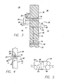
- the first portion 20 includes a pressure responsive device 26 ( Figs. 3-5 ) which includes a passage 28 communicating with a volume and associated pressure on a first side 30 (cockpit 18) of a panel assembly 32 and a passage 34 communicating with a volume and associated pressure on a second side 36 (passenger compartment 19) of the panel assembly 32.
- the door or panel assembly 32 includes a frame structure 38 and a panel 40.
- the panel 40 includes a free end 42 and a movably retained end 44. As indicated by the arrows 46, 48, the panel 40 can swing towards the first side 30, the second side 36, or swing between both sides 30, 36.
- the movement of the panel 40 depends upon the retaining structure 50, such as a hinge structure, which attaches the retained end 44 to a second portion 51 of the frame structure 52.
- the free end 42 of the door panel 40 moves relative to the retained end 44 by way of the retaining means 52 to move the panel relative to the second portion 51 of the frame structure 52.
- the first and second portions 20, 22 are attached to respective, generally proximate areas on the panel 40 and frame 38.
- the portions, 20, 22 make up the latching device 24.
- the latching device 24 includes a mechanism which selectively engages the portions 20, 22 to providing a resistance force which resists separation of the panel 40 from the corresponding frame 38.
- the retaining force is generally illustrated as a mechanical arrangement whereby one mechanism engages a corresponding area to prevent dislodgement of the panel 40 from the frame 38.
- the portions 20, 22 making up the latching mechanism 24 may also have a magnetic force such that the magnetic force resists displacement of the door panel 40 relative to the frame 38.
- the mechanism includes a bolt 78 which engages a corresponding second portion the frame 38 of prevent disengagement of the panel 40 from the frame 38.
- the device whether it is mechanical or magnetic is acted on, responsive to, and/or affected or controlled by the pressure detected by or acting on the pressure responsive device 26.
- the pressure responsive device 26 is embodied in one form as shown in Fig. 5 as a pressure cylinder or pneumatic piston which moves a plunger 58 through the cylinder structure 60.
- Engaging structures 62, 64 are associated with the latching device 24 to either engage or disengage the corresponding portion 22.
- the engaging structures 62, 64 are attached to appropriate structures such that when the plunger 58 is moved, the latching device 24 will either engage or disengage to facilitate locking or unlocking of the latching device 24. Further details as to the mechanical latching structures retained in the latching device 24 are provided herein below.
- the pressure responsive device may be in the form of a diaphragm which is coupled to the latching device 24.
- Another form of the pressure responsive device 26 is generally responsive to pressure on one side of the device.
- this form of the device 26 may or may not communicate with both sides of the panel.
- a dramatic, sudden change in pressure will cause a rapid shift in the output of the output of the pressure responsive device 26 causing the desired pressure responsive effect on the latching mechanism.
- Such a change in pressure is generally so large on one side of the panel that the pressure change on the other side of the panel is negligible. Such a pressure change might occur rapid in a decompression event.
- Fig. 4 shows an embodiment in which the latching device 24 is integrated into the panel and the panel 40 and frame 38 structures.
- the first and second components 20, 22 are attached to a corresponding first surface 30.
- This allows the latching device 24 to be attached to any corresponding surfaces as well as allowing the latching device 24 to be retrofitted to a door assembly 32.
- the embodiment as shown in Fig. 4 allows the latching device 24 to be integrated into the design and construction of the panel assembly.
- the embodiment as shown in Fig. 4 employs the same general principles of the method, system and apparatus as disclosed and discussed with regard to Figs. 1-3 .
- first and second portions 20, 22 may be reversed relative to the panel 40 and frame 38.
- first structure 20 as shown in Figure 3 on the frame 38 could be attached to the panel 40 and the structure 22 attached to the panel 40 could be attached to the frame 38.
- the general method and function of the latching device 24 will remain the same.
- the objective of the latching device 24 is to retain the panel 40 in a closed position relative to the frame 38 under the general circumstances in which the pressure identified as P1 on the first side 30 of the door is generally equal to the pressure P2 on the second side 36 of the panel.
- the first and second portions will disengage. Disengagement of the portions will result in opening or disengagement of the panel 40 relative to the frame 38.
- P1 is the pressure in a flight deck area
- P2 is the pressure in a passenger compartment
- a change in the pressures or pressure differential relative to either side of the panel 40 creates a force on one side of the panel. For example, if the pressure in the passenger compartment 19, P2, is reduced a force will be imposed on the panel 40 drawing the panel 40 towards the passenger compartment 19.
- the latching device 24 resists disengagement of the panel 20 from the frame 38 and as such the panel 40 will not open. However, by operation of the pressure responsive device 26, the mechanism which cooperates with the pressure responsive device 26 will become disengaged allowing the panel 40 to move relative to the frame 38.
- This operation of the latching device 24 allows the panel 40 to remain closed and latched to prevent unintended, forced or accidental entry, access to or displacement of the panel yet allows the panel to become displaced as a result of disengaging the latching device 24 in response to a pressure differential. This prevents the panel 40 or surrounding structure from becoming damaged or forcibly removed from the frame 38 due to a pressure differential.
- the first and second portions 20, 22 may be in the form of a latch and keeper or detent and receiver as well as a variety of other mechanical structures.
- the portions 20, 22 could be in the form of electrical devices which operate mechanisms under the influence of electrical signals.
- the pressure responsive device 26 could operate on an electrical signal in response to an electrical detection of pressure and variations. The signal would be received by a controller which would then operate a related electrical mechanism to move a mechanical device. Alternately, the electrical pressure detection signal could be used to operate an electro-magnet which would then provide the latching function between the first and second portions 20, 22.
- the latching device 24 could be positioned at the hinge 50 to prevent movement of the door relative to the frame.
- the moment arm 70 created by a force 72 on the panel 40 relative to the hinge 50 may require stronger mechanisms to prevent overriding the latching device 24.
- the latching device 24 with the pressure responsive device 26 may be used with a single panel covering a single opening, it is understood that some doors have multiple openings.
- the latching device 24 as shown in Fig. 6 may be employed on each of such multiple panels as necessary.
- the latching device 24 may be adjusted to allow venting of one panel at one pressure differential, a second panel at a second differential, and so on. This staged opening of the panels prevents opening of all the panels upon the development of a single pressure differential. In the event that the pressure differential is minor, one panel may be opened to provide the necessary level of equalization of the pressures.
- a second and subsequent panels may be opened in order to help equalize the pressures in a controlled manner. This staged opening of the panels 40 allows for more controlled pressure venting relative to the multiple panels.
- Fig. 6 shows the latching mechanism 24 in which the first portion 20 includes the pressure sensing device 26 and an associated dead bolt assembly 70.
- the dead bolt assembly 70 includes a dead bolt arm 78 pivotally retained in the assembly.
- a manual actuation mechanism in the form of an actuator 72 attached to the plunger 58 allows for manual activation of the dead bolt 70 even when P1 is approximately equal to P2. It will be appreciated that such a manual actuation mechanism may be embodied in many different forms and provide the same or equivalent function.
- the first portion 20 is shown attached to the frame 38 and the second portion 22 is in the form of a recess or keeper 76 in the door panel 40.
- a free-end 78 of the dead bolt arm 79 extends from the frame 38 and into the recess 76.
- the structures and devices described herein may have many different forms. The structures and devices shown and described herein may be represented in a simplified form in the interest of simplifying the description of the disclosure to improve understanding and illustrate the broad scope of this disclosure.
- the dead bolt assembly 70 resists door opening loads on the door panel 40.
- the system can be designed to resist loads of several thousand pounds. Such a system will involve scaling and designing the first and second portions 20, 22 of sufficient size, dimension and materials so as to resist such loading.
- a biasing assembly 90 in the form of a first spring 92 and second spring 94 are provided on either side of the plunger 58 to provide a centering effect.
- the centering effect as a result of the size and dimension of the arm 80 and attachment to the dead bolt 70 helps to maintain the dead bolt in a generally centered position in the recess 76.
- the manual actuator 72 is provided to manually displace the dead bolt 70 by applying a force 98 to the actuator 72. As can been seen from Fig. 6 , pushing downwardly 98 on the actuator 72 causes the arm 80 to push downwardly on the pivotally 82 connected dead bolt 70 thereby rotating the dead bolt 70 about pivot point 84 disengaging the free-end 78 from the recess 76. It is envisioned that one of ordinary skill in the art, informed by the teachings of the present disclosure, could develop a configuration of the actuator 72 to facilitate manual movement of the dead bolt 79 by lifting up on the actuator 72. This embodiment is considered to be within the scope of this disclosure.
- the embodiments as shown Figs. 7 and 8 provide the ability to attach the latching mechanism to the surfaces of the door assembly 32, build the latching mechanism into the panel assembly structure as well as, retrofit the latching mechanism 24 to existing panel assemblies 32.
- the structure 20 includes a housing 100 integrally formed as a single piece body. A flange 102 extending from the housing 100 allows for fasteners 104 to be attached thereto thereby fastening the integral housing 100 to the corresponding surface.
- the second structure 22 is integrally formed with flanges for attaching fasteners 104 to facilitate attachment to a corresponding surface.
- the embodiment as shown in Figs. 7 and 8 also include the pressure sensitive device 26.
- a vent tube 108 is provided to provide pressure venting of the pressure sensitive device 26 to the second side 36.
- the manual actuator 72 extends from the portion of the sensing device 26 and connects to the dead bolt 70.
- Fig. 7 The latching mechanism of Fig. 7 is shown in a perspective view which has been cross- sectioned in Fig. 8 . Shown in Fig. 8 , the dead bolt 70 rotates 83 about point 84. While the orientation of the pressure sensing device 26 is changed in this embodiment relative to that as shown in Fig. 4 , general operation is still approximately the same as that as shown in Fig. 6 .
- the dead bolt latching mechanism 24 as shown in Figs. 6-8 is attached to or integrated in the panel assembly 32.
- the dead bolt 70 engages a corresponding recess 75 defined by a keeper 76 to prevent disengagement of the door from the frame.
- the dead bolt latching mechanism 24 includes a pressure sensing device 26 which is coupled or, as described above, otherwise operatively connected to the dead bolt 70 to operate the dead bolt 70 or otherwise have an effect on the dead bolt 70, in response to the pressure sensed by the pressure sensing device 26. If the pressure, P2 drops relative to the pressure P1, the dead bolt 70 will rotate about 84 to disengage the free-end 78 of the dead bolt from the keeper 76.
- a manual actuator 72 is provided to manually disengage the dead bolt 70 from the keeper 76 regardless of the pressures P1, P2. Also, if the pressure P2 is less than the pressure P1, which would ordinarily disengage the dead bolt from the keeper 76, but for some reason does not operate properly, the manual actuator 72 can be used to disengage the dead bolt 70 from the keeper 76.
- the dead bolt latching mechanism 24 shown in Figs. 9-11 includes the first portion 20 and the second portion 22.
- the first portion 20 includes housing 300 and the pressure sensing device 26 in the form of an air cylinder 302.
- Flanges 304 are provided on the housing 300 to attach the dead bolt latching mechanism 24 to a door panel 40.
- the dead bolt latching mechanism 24 includes a rotating bolt 310 rotatably retained in the housing by a pin 312.
- the bolt 310 includes a protrusion 314 which engages a corresponding recess 75 of the keeper 76 of the second portion 22.
- the second portion 22 provides a keeper 76, which, when engaged with the protrusion 314, prevents the latching mechanism 24 from being disengaged.
- the lock assembly 320 includes a ring portion 322 attached to a shaft 324.
- the shaft 324 is retained in an axial passage 325 extending through the housing 300 and the air cylinder 302 for axial movement there through.
- the shaft 324 moves relative to the bolt 310 upon movement of the piston 58 in response to the air pressure P1 and P2.
- the ring portion 322 defines a passage 326 there through. Additionally, in the embodiment shown in Fig. 12 , the ring 322 extends outwardly from the shaft 324 to engage passages 330 formed on the inside surface of the housing 300. This allows for controlled movement of the ring 322 relative to the bolt 310.
- the shaft 324 is connected to the piston or plunger 58 which is retained inside the cavity 332 of the air cylinder 302.
- the air cylinder communicates with separate areas through passages 334 and 336.
- 334 communicates with the flight deck whereas passage 336 may be used to communicate with the passenger compartment.
- the pressures P1 and P2 can act on the piston 58 retained within the cylinder 302. Changes in the pressures P1, P2 will cause the piston 58 to shift within the cylinder 302 thereby causing movement 340 of the lock 320.
- Springs 344 are provided on either side of the piston 58 to balance the piston generally equally in the cylinder 302. The springs also provide a force which generally resist aberrant movement of the piston 58 due to minor momentary pressure changes. Further, a manual actuator 72 is provided and attached to the shaft 324 for manually overriding the normally latched condition of the bolt 310 in the keeper 76.
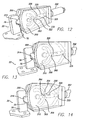
- Fig. 12 is a perspective view showing the bolt 310 in a locked position with the lock 320 generally preventing movement of the bolt 310.
- the bolt 310 includes a pair of spaced arcuate arms 350, 352. Acruate arms 350, 352 have free-ends 354, 356 which define a gap 358 there between. A leading edge 360 of the lock is positioned in the space 358 to prevent rotation of the bolt.
- the panel to which the housing 300 is attached is rotated or moved slightly.
- Movement of the housing 300 imposes a force on the bolt 310 which might slightly rotate the bolt 310 as a result of the protrusion 314 being retained in the keeper 76.
- the bolt 310 is prevented from rotating. As such, the bolt 310 cannot be rotated when the lead edge 360 is positioned in the gap 358 and as a result the protrusion 314 is retained in the keeper 76.
- the lock 320 has been moved forwardly due to either actuation by the manual actuator 72 or a differential in pressures P1, P2.
- P1 decreases
- the resulting differential will be a relative increase in P2.
- the relative increase in P2 will cause the piston 58 to shift towards the bolt 310 resulting in movement of the bolt 310 so that the free-ends 354, 356 of the bolt 310 will be allowed to pass through the gap 326, the ring 322.
- the continued movement of the panel to which the housing 300 is attached causes the continued rotation of the bolt 310 as a result of the protrusion 314 being driven against the keeper 76.
- the bolt 310 is shown to be rotated in Figs. 17 and 18 in response to a retraction of the lock away from the bolt 310.
- Retraction of the lock is caused by a differential in pressures P1, P2.
- P1, P2 When P2 is decreased, the relative effect will be increase P1, thereby causing the plunger 58 to shift away from the old 310.
- the bolt 310 will rotate since the leading edge 360 of the lock 320 no longer interferes with free rotation of the bolt. In this manner, once the lock is withdrawn away from the bolt 310, the free-end 354 of the arm 350 is allowed to pass in front of the leading edge 360.
- the extending arms 350, 352 of the bolt 310 allow the bolt to be a symmetric design which facilitates operation of the bolt in both directions of swing of the door 40.
- the symmetric design allows for manual actuation of the latching mechanism by use of the manual actuator 72 and swinging of the door 40 in either direction. It should be noted that with reference Fig. 10 , manual actuation requires that the arms 350, 352 be allowed to pass through the gap 326 in the lock 320. As such, interaction of the protrusion and keeper 76 will allow the door to open in either direction.
Landscapes
- Engineering & Computer Science (AREA)
- Aviation & Aerospace Engineering (AREA)
- Mechanical Engineering (AREA)
- Power-Operated Mechanisms For Wings (AREA)
- Measuring Fluid Pressure (AREA)
- Lock And Its Accessories (AREA)
- Switches Operated By Changes In Physical Conditions (AREA)
- Connection Of Plates (AREA)
Description
- The present disclosure relates to a method, system and apparatus for a latching device which operates in response to a pressure differential between a first side and a second side of a barrier to allow a panel associated with the barrier to release upon a given set or range of pressure conditions.
- By way of review, a variety of latching systems have been developed to maintain doors and other structures in a closed position. The reference to panels, doors and other structures relates to the use of latching devices to retain a first body such as a panel relative to a second body, such as a frame. With regard to the example of panels, a panel includes one portion which might be rotatably hinged or otherwise movably retained on a corresponding structure such as a frame. The panel serves to close or cover at least a portion of an opening defined by the frame for a variety of purposes including providing a barrier to prevent passage through the opening. Document
WO8401404 claim 1. - A variety of latching devices have been developed to facilitate the movement or "blowout" of a panel relative to the frame. Such blowout latching devices have been developed by Hartwell Corporation, assignee of the present disclosure to facilitate disengagement of a panel from a frame or other structure under a set or range of "blowout" conditions. For example, if pressure builds up within an area at least partially housed or contained by the panel, the pressure differential will rise to a point where the panel may be forcibly removed, disengaged or "blown out" from the frame by force associated with the pressure differential. Under these conditions, it is desirable to set the blowout force at a level or range so that premature disengagement of the panel from the primary structure does not occur. In this situation, the blow out load level can be set so that a predetermined pressure differential disengages the panel from the primary structure to protect and preserve the integrity of the frame and any related structures and devices.
- In some situations, it would be desirable to maintain a door in a closed position under one level or range of pressure conditions yet release the door under a second range or set of conditions. Such level or range may or may not overlap or may be discrete ranges or, in fact, points. The panel in such a situation generally is in an environment where the pressure on either side of the door is generally equalized. The door may include a sealing structure to prevent the unwanted or abrupt passage of air there through. However, the pressure on either side of the door is generally equal.
- One example of the use of such a panel in a well-known environment is the use of a panel in a pressurized cabin such as in an aircraft. The panel may be employed as a barrier to separate the flight crew, passengers and/or cargo into discrete areas. Such a panel may be used between the flight deck and passenger compartment as well as perhaps between the passenger compartment and corresponding storage area which is not occupied by passengers. In the situation in which the panel is used on an aircraft in which the cabin is pressurized, it may be desirable to maintain the door in a closed position for many situations but allow the panel to be opened when the pressure differential between the two compartments changes. Such a pressure differential may occur in the case where cabin pressure drops in the cargo compartment due to a leak or other loss of pressure. Under these circumstances, it might be desirable to allow the cabin to generally equalize to avoid or minimize damage which might result from the pressure differential.
- Similarly, in a situation where a panel is positioned between the flight deck and the passengers, it may be desirable to release the panel and equalize the pressure between the flight deck and passenger area. In the situation in which the panel is positioned between the flight deck and passenger area, it might be desirable to allow the panel to disengage, rather than having the panel structurally fail as a result of the pressure differential.
- For example, the panel to the flight deck generally is maintained in a closed and latched position while in flight to maintain privacy of the flight crew. This prevents the passage of passengers into the flight deck area. Increased latching strength is required in order to prevent a passenger from forcibly opening the door. However, in a situation in which pressure is lost in the passenger compartment, it may be desirable to allow the panel to release in order to prevent the panel from being forcibly removed from the structure by the pressure differential. This would help prevent injury to passengers if the panel were forcibly removed from the frame and expelled into the passenger compartment. By allowing the panel to release in response to the pressure differential between the flight deck and passenger compartment, the panel will open thereby providing increased safety. Similarly, if the pressure differential occurs as a result of loss of pressure in the flight deck, the panel will be allowed to disengage the frame, yet be retained thereon, to provide pressure equalization to prevent injury to the flight crew and equipment. Further, a pressure differential on the panel creates forces which could damage the bulkhead to which the panel is attached possibly damaging the associate portion of the airframe. Release of the panel eliminates the forces imposed on the airframe thereby eliminating a possible source of damage to the airframe.
- With the foregoing in mind, it would be desirable to provide a method, system and apparatus to provide unlatching of the door latch under a range or set of pressure differential circumstances. The present disclosure seeks to provide an improved, novel latching system which operates in response to a pressure differential. Accordingly, the present invention provides a dead bolt latching device as defined in
claim 1, a dead bolt latching system as defined inclaim 14 and a method for controllably latching a panel as defined inclaim 16 - The detailed description particularly refers to the accompanying figures in which:
-
Fig. 1 is a partial fragmentary view of a portion of an aircraft having a barrier which is positioned between a cockpit area and a passenger area; -
Fig. 2 is a diagrammatic cross-sectional view taken along line 2-2 inFig. 1 showing a panel in the barrier employing a latching device as disclosed; -
Fig. 3 is a diagrammatic cross-sectional view taken along line 3-3 inFig. 2 ; -
Fig. 4 is a cross-sectional view similar to that as shown inFig. 3 showing an embodiment of the latching device; -
Fig. 5 is an enlarged diagrammatic illustration of à pressure responsive device as employed in the present disclosure; -
Fig. 6 is a diagrammatic illustration of the latching mechanism; -
Fig. 7 is a perspective view of an embodiment of the diagrammatic latching mechanism shown inFig. 5 ; -
Fig. 8 is a partial fragmentary cross-sectional view taken along line8-8 inFig. 7 ; -
Fig. 9 is a top plan view of an embodiment of the latching mechanism; -
Fig. 10 is a cross-sectional, side elevational view of the latching mechanism inFig. 9 taken along line 10-10 inFigure 9 . -
Fig. 11 is a side elevational view of the latching mechanism shown inFig. 9 taken along line 11-11 inFig. 9 ; and -
Figs. 12-18 are perspective views showing operation of the latching mechanism as shown inFigs. 9-11 ,Figs. 12 and 13 showing the mechanism preventing disengagement of a bolt from a keeper,Figs. 14-16 showing movement of the bolt through a locking structure,Figs. 17 and 18 showing movement of the bolt upon displacement of the locking structure. - While the present disclosure may be susceptible to embodiment in different forms, there is shown in the drawings, and herein will be described in detail, embodiments with the understanding that the present description is to be considered an exemplification of the principles of the disclosure and is not intended to limit the disclosure to the details of construction and the arrangements of components set forth in the following description or illustrated in the drawings.
-
Fig. 1 shows a fragment of a front section of anaircraft 14 in which a portion of the outside of theaircraft 14 has been broken away to illustrate abarrier 16. Thebarrier 16 divides aninternal compartment 17 to separate a flight deck orcockpit area 18 from apassenger area 19. As it will be described in detail herein below, the present disclosure helps to prevent unpermitted access from thepassenger compartment 19 to thecockpit 18. Also, the disclosure allows automatic opening of thebarrier 16 in the event of depressurization in either thecockpit 18 orpassenger compartment 19. -
Fig. 2 provides a general diagrammatic illustration taken along line 2-2 inFig. 1 showing a view from thecockpit area 18 facing thebarrier 16. As shown generally inFig. 2 , the disclosure includes afirst portion 20 and asecond portion 22 comprising thelatching mechanism 24. In the embodiment shown, thefirst portion 20 includes a pressure responsive device 26 (Figs. 3-5 ) which includes apassage 28 communicating with a volume and associated pressure on a first side 30 (cockpit 18) of apanel assembly 32 and apassage 34 communicating with a volume and associated pressure on a second side 36 (passenger compartment 19) of thepanel assembly 32. - The door or
panel assembly 32 includes aframe structure 38 and apanel 40. Thepanel 40 includes afree end 42 and a movably retainedend 44. As indicated by thearrows panel 40 can swing towards thefirst side 30, thesecond side 36, or swing between bothsides panel 40 depends upon theretaining structure 50, such as a hinge structure, which attaches the retainedend 44 to asecond portion 51 of theframe structure 52. In summary, thefree end 42 of thedoor panel 40 moves relative to the retainedend 44 by way of the retaining means 52 to move the panel relative to thesecond portion 51 of theframe structure 52. - The first and
second portions panel 40 andframe 38. The portions, 20, 22 make up the latchingdevice 24. As will be described in greater detail herein below, the latchingdevice 24 includes a mechanism which selectively engages theportions panel 40 from the correspondingframe 38. In this regard, thepanel 40 is retained or locked in position until other pressure related conditions are met. The retaining force is generally illustrated as a mechanical arrangement whereby one mechanism engages a corresponding area to prevent dislodgement of thepanel 40 from theframe 38. It is also envisioned theportions latching mechanism 24 may also have a magnetic force such that the magnetic force resists displacement of thedoor panel 40 relative to theframe 38. As shown in the embodiment ofFigs. 6-13 the mechanism includes abolt 78 which engages a corresponding second portion theframe 38 of prevent disengagement of thepanel 40 from theframe 38. - The device, whether it is mechanical or magnetic is acted on, responsive to, and/or affected or controlled by the pressure detected by or acting on the pressure
responsive device 26. The pressureresponsive device 26 is embodied in one form as shown inFig. 5 as a pressure cylinder or pneumatic piston which moves aplunger 58 through thecylinder structure 60. Engagingstructures device 24 to either engage or disengage the correspondingportion 22. The engagingstructures plunger 58 is moved, the latchingdevice 24 will either engage or disengage to facilitate locking or unlocking of the latchingdevice 24. Further details as to the mechanical latching structures retained in the latchingdevice 24 are provided herein below. Further, the pressure responsive device may be in the form of a diaphragm which is coupled to the latchingdevice 24. - Another form of the pressure
responsive device 26 is generally responsive to pressure on one side of the device. In this regard, this form of thedevice 26 may or may not communicate with both sides of the panel. In this embodiment, a dramatic, sudden change in pressure will cause a rapid shift in the output of the output of the pressureresponsive device 26 causing the desired pressure responsive effect on the latching mechanism. Such a change in pressure is generally so large on one side of the panel that the pressure change on the other side of the panel is negligible. Such a pressure change might occur rapid in a decompression event. -
Fig. 4 shows an embodiment in which thelatching device 24 is integrated into the panel and thepanel 40 and frame 38 structures. With reference toFigs. 2 and3 , the first andsecond components first surface 30. This allows the latchingdevice 24 to be attached to any corresponding surfaces as well as allowing the latchingdevice 24 to be retrofitted to adoor assembly 32. The embodiment as shown inFig. 4 allows the latchingdevice 24 to be integrated into the design and construction of the panel assembly. The embodiment as shown inFig. 4 employs the same general principles of the method, system and apparatus as disclosed and discussed with regard toFigs. 1-3 . - It should also be noted that the first and
second portions panel 40 andframe 38. In this regard, for example, thefirst structure 20 as shown inFigure 3 on theframe 38 could be attached to thepanel 40 and thestructure 22 attached to thepanel 40 could be attached to theframe 38. Regardless of the position of the portions, 20, 22, the general method and function of the latchingdevice 24 will remain the same. In this regard, the objective of the latchingdevice 24 is to retain thepanel 40 in a closed position relative to theframe 38 under the general circumstances in which the pressure identified as P1 on thefirst side 30 of the door is generally equal to the pressure P2 on thesecond side 36 of the panel. It is expected that a range of equivalent pressure differentials would be permitted to allow some degree of variation in pressure differential between thefirst side 30 and thesecond side 36. However, the range would be defined to provide some practical limit whereby the latchingdevice 24 would eventually allow disengagement of the first andsecond portions panel 40 to be displaced relative to theframe 38. - For example, if the pressure on the
first side 30 is decreased relative to thesecond side 36 such that P1 is less than P2 and the pressure differential or the difference between P1 and P2 is substantial enough based on the criteria established for the system to justify disengagement of the first andsecond portions panel 40 relative to theframe 38. For example, if P1 is the pressure in a flight deck area and P2 is the pressure in a passenger compartment, a change in the pressures or pressure differential relative to either side of thepanel 40 creates a force on one side of the panel. For example, if the pressure in thepassenger compartment 19, P2, is reduced a force will be imposed on thepanel 40 drawing thepanel 40 towards thepassenger compartment 19. The latchingdevice 24 resists disengagement of thepanel 20 from theframe 38 and as such thepanel 40 will not open. However, by operation of the pressureresponsive device 26, the mechanism which cooperates with the pressureresponsive device 26 will become disengaged allowing thepanel 40 to move relative to theframe 38. This operation of the latchingdevice 24 allows thepanel 40 to remain closed and latched to prevent unintended, forced or accidental entry, access to or displacement of the panel yet allows the panel to become displaced as a result of disengaging the latchingdevice 24 in response to a pressure differential. This prevents thepanel 40 or surrounding structure from becoming damaged or forcibly removed from theframe 38 due to a pressure differential. - As will be described in greater detail as follows, the first and
second portions portions responsive device 26 could operate on an electrical signal in response to an electrical detection of pressure and variations. The signal would be received by a controller which would then operate a related electrical mechanism to move a mechanical device. Alternately, the electrical pressure detection signal could be used to operate an electro-magnet which would then provide the latching function between the first andsecond portions device 24 could be positioned at thehinge 50 to prevent movement of the door relative to the frame. However, it will be appreciated that themoment arm 70 created by aforce 72 on thepanel 40 relative to thehinge 50 may require stronger mechanisms to prevent overriding the latchingdevice 24. With this in mind, it may be desirable to provide the latching device relative to the free-end 42 of thepanel 40. - While it is envisioned that the latching
device 24 with the pressureresponsive device 26 may be used with a single panel covering a single opening, it is understood that some doors have multiple openings. In this regard, the latchingdevice 24 as shown inFig. 6 may be employed on each of such multiple panels as necessary. Additionally, the latchingdevice 24 may be adjusted to allow venting of one panel at one pressure differential, a second panel at a second differential, and so on. This staged opening of the panels prevents opening of all the panels upon the development of a single pressure differential. In the event that the pressure differential is minor, one panel may be opened to provide the necessary level of equalization of the pressures. If the opening of a single panel is insufficient over a given period of time and the pressure differential is still maintained or if it increases, a second and subsequent panels may be opened in order to help equalize the pressures in a controlled manner. This staged opening of thepanels 40 allows for more controlled pressure venting relative to the multiple panels. - Turning now to a specific embodiment of the present disclosure, the disclosure as shown and described and
Figs. 6-8 will be described. -
Fig. 6 shows thelatching mechanism 24 in which thefirst portion 20 includes thepressure sensing device 26 and an associateddead bolt assembly 70. As shown and described, thedead bolt assembly 70 includes adead bolt arm 78 pivotally retained in the assembly. A manual actuation mechanism in the form of anactuator 72 attached to theplunger 58 allows for manual activation of thedead bolt 70 even when P1 is approximately equal to P2. It will be appreciated that such a manual actuation mechanism may be embodied in many different forms and provide the same or equivalent function. Thefirst portion 20 is shown attached to theframe 38 and thesecond portion 22 is in the form of a recess orkeeper 76 in thedoor panel 40. A free-end 78 of thedead bolt arm 79 extends from theframe 38 and into therecess 76. The structures and devices described herein may have many different forms. The structures and devices shown and described herein may be represented in a simplified form in the interest of simplifying the description of the disclosure to improve understanding and illustrate the broad scope of this disclosure. - When the pressures P1 and P2 are approximately equal, the
dead bolt assembly 70 resists door opening loads on thedoor panel 40. The system can be designed to resist loads of several thousand pounds. Such a system will involve scaling and designing the first andsecond portions - When P1 and P2 are not generally equal as a result of a pressure differential between the
first side 30 andsecond side 36, anarm 80 attached to thepiston 58 shifts as a result of the pressure differential. Thearm 80 is connected pivotally 82 to thedead bolt 70. It should also be noted that thedead bolt 70 is pivotally connected 84 to theframe 38. As a result of the pressure differentials between P1 and P2, the free-end 78 of thedead bolt 70 rotates relative to thedoor panel 40. Continued rotation of the free-end 78 relative to therecess 76 under sufficient pressure differential betweenP 1 and P2 results in disengagement of the free-end 78 from therecess 76. As a result, thedoor panel 40 may be opened without interference from thedead bolt 70. - In the present embodiment, a biasing
assembly 90 in the form of afirst spring 92 andsecond spring 94 are provided on either side of theplunger 58 to provide a centering effect. The centering effect as a result of the size and dimension of thearm 80 and attachment to thedead bolt 70 helps to maintain the dead bolt in a generally centered position in therecess 76. - The
manual actuator 72 is provided to manually displace thedead bolt 70 by applying aforce 98 to theactuator 72. As can been seen fromFig. 6 , pushing downwardly 98 on theactuator 72 causes thearm 80 to push downwardly on the pivotally 82 connecteddead bolt 70 thereby rotating thedead bolt 70 aboutpivot point 84 disengaging the free-end 78 from therecess 76. It is envisioned that one of ordinary skill in the art, informed by the teachings of the present disclosure, could develop a configuration of theactuator 72 to facilitate manual movement of thedead bolt 79 by lifting up on theactuator 72. This embodiment is considered to be within the scope of this disclosure. - It should be noted that the embodiments as shown
Figs. 7 and 8 provide the ability to attach the latching mechanism to the surfaces of thedoor assembly 32, build the latching mechanism into the panel assembly structure as well as, retrofit thelatching mechanism 24 to existingpanel assemblies 32. For example, thestructure 20 includes ahousing 100 integrally formed as a single piece body. Aflange 102 extending from thehousing 100 allows forfasteners 104 to be attached thereto thereby fastening theintegral housing 100 to the corresponding surface. Similarly, thesecond structure 22 is integrally formed with flanges for attachingfasteners 104 to facilitate attachment to a corresponding surface. The embodiment as shown inFigs. 7 and 8 also include the pressuresensitive device 26. Avent tube 108 is provided to provide pressure venting of the pressuresensitive device 26 to thesecond side 36. Ahole 110 in thehousing 100 vents pressure to thefirst side 30. Themanual actuator 72 extends from the portion of thesensing device 26 and connects to thedead bolt 70. - The latching mechanism of
Fig. 7 is shown in a perspective view which has been cross- sectioned inFig. 8 . Shown inFig. 8 , thedead bolt 70 rotates 83 aboutpoint 84. While the orientation of thepressure sensing device 26 is changed in this embodiment relative to that as shown inFig. 4 , general operation is still approximately the same as that as shown inFig. 6 . - In use, the dead
bolt latching mechanism 24 as shown inFigs. 6-8 is attached to or integrated in thepanel assembly 32. Thedead bolt 70 engages acorresponding recess 75 defined by akeeper 76 to prevent disengagement of the door from the frame. The deadbolt latching mechanism 24 includes apressure sensing device 26 which is coupled or, as described above, otherwise operatively connected to thedead bolt 70 to operate thedead bolt 70 or otherwise have an effect on thedead bolt 70, in response to the pressure sensed by thepressure sensing device 26. If the pressure, P2 drops relative to the pressure P1, thedead bolt 70 will rotate about 84 to disengage the free-end 78 of the dead bolt from thekeeper 76. Similarly, if the pressure P1 decreases relative to the pressure P2, theplunger 58 will be moved and thedead bolt 70 will be rotated out of engagement with thekeeper 76recess 75. Also, amanual actuator 72 is provided to manually disengage thedead bolt 70 from thekeeper 76 regardless of the pressures P1, P2. Also, if the pressure P2 is less than the pressure P1, which would ordinarily disengage the dead bolt from thekeeper 76, but for some reason does not operate properly, themanual actuator 72 can be used to disengage thedead bolt 70 from thekeeper 76. - Turning now to a specific embodiment of the disclosure as shown and described and
Figs. 9-18 will be described. - The dead
bolt latching mechanism 24 shown inFigs. 9-11 includes thefirst portion 20 and thesecond portion 22. Thefirst portion 20 includeshousing 300 and thepressure sensing device 26 in the form of anair cylinder 302.Flanges 304 are provided on thehousing 300 to attach the deadbolt latching mechanism 24 to adoor panel 40. The deadbolt latching mechanism 24 includes arotating bolt 310 rotatably retained in the housing by apin 312. Thebolt 310 includes aprotrusion 314 which engages acorresponding recess 75 of thekeeper 76 of thesecond portion 22. Thesecond portion 22 provides akeeper 76, which, when engaged with theprotrusion 314, prevents thelatching mechanism 24 from being disengaged. Rotation of therotatable bolt 310 is controlled as a result of the position of alock assembly 320. Thelock assembly 320 includes aring portion 322 attached to ashaft 324. Theshaft 324 is retained in anaxial passage 325 extending through thehousing 300 and theair cylinder 302 for axial movement there through. Theshaft 324 moves relative to thebolt 310 upon movement of thepiston 58 in response to the air pressure P1 and P2. With further reference toFig. 12 , thering portion 322 defines apassage 326 there through. Additionally, in the embodiment shown inFig. 12 , thering 322 extends outwardly from theshaft 324 to engagepassages 330 formed on the inside surface of thehousing 300. This allows for controlled movement of thering 322 relative to thebolt 310. - The
shaft 324 is connected to the piston orplunger 58 which is retained inside thecavity 332 of theair cylinder 302. The air cylinder communicates with separate areas throughpassages passage 336 may be used to communicate with the passenger compartment. As such, in the present embodiment, the pressures P1 and P2 can act on thepiston 58 retained within thecylinder 302. Changes in the pressures P1, P2 will cause thepiston 58 to shift within thecylinder 302 thereby causingmovement 340 of thelock 320. -
Springs 344 are provided on either side of thepiston 58 to balance the piston generally equally in thecylinder 302. The springs also provide a force which generally resist aberrant movement of thepiston 58 due to minor momentary pressure changes. Further, amanual actuator 72 is provided and attached to theshaft 324 for manually overriding the normally latched condition of thebolt 310 in thekeeper 76. - Turning now to
Figures 12-18 , a description of the operation and method of the present deadbolt latching mechanism 24 will be described.Fig. 12 is a perspective view showing thebolt 310 in a locked position with thelock 320 generally preventing movement of thebolt 310. With further reference toFig. 10 , thebolt 310 includes a pair of spacedarcuate arms Acruate arms gap 358 there between. Aleading edge 360 of the lock is positioned in thespace 358 to prevent rotation of the bolt. As shown inFig. 13 , the panel to which thehousing 300 is attached is rotated or moved slightly. Movement of thehousing 300 imposes a force on thebolt 310 which might slightly rotate thebolt 310 as a result of theprotrusion 314 being retained in thekeeper 76. However, because theleading edge 360 is positioned in thegap 358, thebolt 310 is prevented from rotating. As such, thebolt 310 cannot be rotated when thelead edge 360 is positioned in thegap 358 and as a result theprotrusion 314 is retained in thekeeper 76. - In
Fig. 14 , thelock 320 has been moved forwardly due to either actuation by themanual actuator 72 or a differential in pressures P1, P2. For example, if P1 decreases, the resulting differential will be a relative increase in P2. The relative increase in P2 will cause thepiston 58 to shift towards thebolt 310 resulting in movement of thebolt 310 so that the free-ends 354, 356 of thebolt 310 will be allowed to pass through thegap 326, thering 322. The continued movement of the panel to which thehousing 300 is attached causes the continued rotation of thebolt 310 as a result of theprotrusion 314 being driven against thekeeper 76. In other words, as the panel is moved, theprotrusion 314 will be acted on by thekeeper 76 remaining in a fixed position and as a result causing a rotation of thebolt 310. Continued rotation ofbolt 310 is shown inFigs. 15 and 16 such that thearm 352 is rotated substantially through thepassage 326. - In a similar manner, the
bolt 310 is shown to be rotated inFigs. 17 and 18 in response to a retraction of the lock away from thebolt 310. Retraction of the lock is caused by a differential in pressures P1, P2. For example, when P2 is decreased, the relative effect will be increase P1, thereby causing theplunger 58 to shift away from the old 310. Similar to the description of the interaction between theprotrusion 314 andkeeper 22 as provided above, thebolt 310 will rotate since theleading edge 360 of thelock 320 no longer interferes with free rotation of the bolt. In this manner, once the lock is withdrawn away from thebolt 310, the free-end 354 of thearm 350 is allowed to pass in front of theleading edge 360. - The extending
arms bolt 310 allow the bolt to be a symmetric design which facilitates operation of the bolt in both directions of swing of thedoor 40. The symmetric design allows for manual actuation of the latching mechanism by use of themanual actuator 72 and swinging of thedoor 40 in either direction. It should be noted that with referenceFig. 10 , manual actuation requires that thearms gap 326 in thelock 320. As such, interaction of the protrusion andkeeper 76 will allow the door to open in either direction. - While a preferred embodiment of the disclosure is shown and described, it is envisioned that those skilled in the art may devise various modifications and equivalents without departing from the spirit and scope of the disclosure as recited in the following claims.
Claims (6)
- A dead bolt latching device (24) for displaceably retaining a panel (40) relative to a frame (38), the dead bolt latching device comprising:a latch body (100) attachable to at least one of the panel (40) and the frame (38);a dead bolt assembly (70) displaceably carried on the latch body (100);a portion (78) of the dead bolt assembly abutting in the mounted condition of the device a portion (76) of the other of the panel and the frame for preventing displacement of the panel from the frame;a pressure responsive device (26) for detecting at least one of a pressure differential between two sides of the panel and a decrease in pressure on one side of the panel characterized in that the pressure responsive device includes a pressure responsive diaphragm or a pneumatic piston (58) operatively retained in a chamber (60), the chamber including a first opening communicating with a first volume and a second opening communicating with a second volume, a pressure differential between the first volume and second volume acting on the pressure responsive diaphragm or piston in the chamber; and in thatthe pressure responsive device(26) is coupled with the dead bolt assembly (70) for responsively operating the dead bolt assembly in response to a pressure differential.
- The dead bolt latching device of claim 1, wherein the dead bolt assembly (70) includes a dead bolt which is pivotably retained relative to the latch body (100).
- The dead bolt latching device of claim 1, wherein the pressure responsive device (26) is carried on the latch body (100).
- A dead bolt latching system for displaceably retaining a plurality of panels (40) relative to a frame (38), the dead bolt latching system comprising:at least one dead bolt latching device (24) as defined in any of the preceding claims, operatively associated with each of the plurality of the panels, the dead bolt latching device (24) retaining the corresponding panel in position relative to the frame (38).
- The dead bolt latching system of claim 4, wherein the pressure responsive device (26) is separate from the latch body (100).
- A method for controllably latching a panel (40) relative to a frame (38), the latching method being responsive to at least one of a pressure differential detected on two, generally opposite sides of a panel and a decrease in pressure on one side of the panel and disengaging a dead bolt (70) from the panel upon the development of a predetermined degree of pressure differential or pressure, the method comprising the steps of:providing a dead bolt latching device (24) operatively associated with the panel;providing a dead bolt (70) displaceably carried on the dead bolt latching device (24), the dead bolt being operatively associated with the panel;providing a pressure responsive device (26) operatively coupled to the dead bolt, wherein the pressure responsive device includes a pressure responsive diaphragm or a pneumatic piston (58) operatively retained in a chamber (60), the chamber including a first opening communicating with a first volume and a second opening communicating with a second volume, a pressure differential between the first volume and second volume acting on the pressure responsive diaphragm or piston in the chamber;engaging the dead bolt (70) with the panel (40);retaining the dead bolt in engagement with the panel;operating the pressure responsive device (26) in response to at least one of a pressure differential between two sides of the panel and a decrease in pressure on one side of the panel;disengaging the dead bolt (70) from the panel upon development of a pressure differential of a predetermined degree or pressure; anddisplacing the panel relative to the frame upon disengagement of the dead bolt.
Applications Claiming Priority (3)
| Application Number | Priority Date | Filing Date | Title |
|---|---|---|---|
| US32694301P | 2001-10-04 | 2001-10-04 | |
| US326943P | 2001-10-04 | ||
| PCT/US2002/031911 WO2003029585A2 (en) | 2001-10-04 | 2002-10-04 | Pressure sensing dead bolt |
Publications (3)
| Publication Number | Publication Date |
|---|---|
| EP1438473A2 EP1438473A2 (en) | 2004-07-21 |
| EP1438473A4 EP1438473A4 (en) | 2006-08-02 |
| EP1438473B1 true EP1438473B1 (en) | 2012-12-05 |
Family
ID=23274443
Family Applications (1)
| Application Number | Title | Priority Date | Filing Date |
|---|---|---|---|
| EP20020778455 Expired - Lifetime EP1438473B1 (en) | 2001-10-04 | 2002-10-04 | Pressure sensing dead bolt |
Country Status (5)
| Country | Link |
|---|---|
| US (1) | US7255376B2 (en) |
| EP (1) | EP1438473B1 (en) |
| AU (1) | AU2002340114A1 (en) |
| CA (1) | CA2462788C (en) |
| WO (1) | WO2003029585A2 (en) |
Families Citing this family (44)
| Publication number | Priority date | Publication date | Assignee | Title |
|---|---|---|---|---|
| EP1576248B1 (en) * | 2002-06-14 | 2017-03-01 | Hartwell Corporation | Pressure responsive blowout latch with reservoir |
| FR2868107B1 (en) * | 2004-03-24 | 2007-09-21 | Rbe Sa | SYSTEM FOR OPENING / CLOSING A DOOR FOR ACCESS BETWEEN THE PASSENGER CABIN AND THE COCKPIT OF AN AIRCRAFT |
| US7510223B2 (en) * | 2005-10-13 | 2009-03-31 | Rockwell Automation Technologies, Inc. | Arc resistant electrical enclosure system and method |
| US7712705B2 (en) * | 2006-03-08 | 2010-05-11 | Airbus Deutschland Gmbh | Deceleration device |
| DE102006013519A1 (en) * | 2006-03-23 | 2007-10-11 | BSH Bosch und Siemens Hausgeräte GmbH | Device with a cooking appliance door, an actuator unit and a locking element |
| JP4263208B2 (en) * | 2006-11-13 | 2009-05-13 | 株式会社ジャムコ | Aircraft cockpit door latching device |
| US8925979B2 (en) | 2006-11-30 | 2015-01-06 | Hartwell Corporation | Command latch and pin latch system |
| DE102007027550A1 (en) * | 2007-06-15 | 2008-12-18 | Airbus Deutschland Gmbh | Differential pressure controlled locking mechanism |
| WO2009058386A2 (en) | 2007-11-01 | 2009-05-07 | Adams Rite Aerospace | Decompression vent latching mechanism |
| US8403265B2 (en) * | 2009-09-01 | 2013-03-26 | Textron Innovations, Inc. | Aircraft cabin door pressure vent system |
| US8288811B2 (en) | 2010-03-22 | 2012-10-16 | Micron Technology, Inc. | Fortification of charge-storing material in high-K dielectric environments and resulting apparatuses |
| DE102011015708B4 (en) * | 2011-03-31 | 2013-12-19 | Airbus Operations Gmbh | Locking mechanism for use in a decompression assembly |
| US9212678B2 (en) | 2011-04-14 | 2015-12-15 | John D. Pratt | Fastener and method of installing same |
| EP2644495B1 (en) * | 2012-03-27 | 2015-06-17 | AIRBUS HELICOPTERS DEUTSCHLAND GmbH | Emergency opening system for an aircraft cabin door |
| DE102012006357A1 (en) * | 2012-03-29 | 2013-10-02 | Airbus Operations Gmbh | Pneumatically controlled locking system for the cockpit door of an aircraft |
| US9016631B2 (en) * | 2012-04-09 | 2015-04-28 | R4 Integration, Inc. | Multi-purpose hatch system |
| US20150210373A1 (en) * | 2012-08-17 | 2015-07-30 | Bombardier Inc. | Door assembly for aircraft interior |
| DE102014104921A1 (en) * | 2014-04-07 | 2015-10-08 | Airbus Operations Gmbh | Holding system for a movable component |
| US9567774B1 (en) | 2015-05-15 | 2017-02-14 | Northrop Grumman Systems Corporation | Temporally staged rapid panel access fastener for highly curved panels |
| US9458648B1 (en) | 2015-05-15 | 2016-10-04 | Northrop Grumman Systems Corporation | Rapid panel access fastener for highly curved panels |
| US9845143B2 (en) | 2015-07-20 | 2017-12-19 | Northrop Grumman Systems Corporation | Advanced lock design for ball-lock devices |
| US9611042B1 (en) | 2015-11-19 | 2017-04-04 | International Business Machines Corporation | System for securing an aircraft door |
| US20180016012A1 (en) * | 2016-07-12 | 2018-01-18 | B/E Aerospace, Inc. | System, Methods, and Apparatus for Air Flow Handling in an Aircraft Monument |
| EP3275779B1 (en) * | 2016-07-29 | 2019-11-27 | AIRBUS HELICOPTERS DEUTSCHLAND GmbH | A load transfer interface for a vehicle door, in particular for an aircraft cabin door |
| US11279461B2 (en) * | 2017-06-01 | 2022-03-22 | The Boeing Company | Flight deck barrier door, aircraft comprising flight deck barrier door, and method of using flight deck barrier door |
| CN107939176B (en) * | 2017-11-17 | 2019-08-30 | 国网青海省电力公司 | Lockset and explosion-proof flame-retardant power distribution cabinet comprising same |
| EP3524509B1 (en) * | 2018-02-08 | 2020-10-07 | The Boeing Company | Aircraft privacy door and door frame assembly |
| US10766596B2 (en) * | 2018-02-08 | 2020-09-08 | The Boeing Company | Aircraft privacy door and door frame assembly |
| US11299250B2 (en) * | 2018-02-08 | 2022-04-12 | The Boeing Company | Aircraft privacy door and door frame assembly |
| EP3524513B1 (en) * | 2018-02-08 | 2020-07-15 | The Boeing Company | Aircraft privacy door and door frame assembly |
| US11305860B2 (en) * | 2018-02-08 | 2022-04-19 | The Boeing Company | Aircraft privacy door and door frame assembly |
| NL2020765B1 (en) * | 2018-04-13 | 2019-10-23 | Boeing Co | Aircraft privacy door and door frame assembly |
| EP4450740B1 (en) | 2018-05-17 | 2026-03-11 | Adams Rite Aerospace Inc. | Pyrotechnic latch actuator responsive to a decompression detection system and method |
| US11167926B2 (en) * | 2018-07-17 | 2021-11-09 | Driessen Aerospace Group N.V. | Retainment assembly |
| EP3702264B1 (en) * | 2019-02-28 | 2021-04-21 | AIRBUS HELICOPTERS DEUTSCHLAND GmbH | A door system with a deceleration mechanism |
| CN110173583B (en) * | 2019-05-27 | 2020-09-04 | 杭州富阳松连食品有限公司 | Self-weight breather valve capable of achieving segmented pressure presetting for edible oil storage tank |
| ES2957619T3 (en) * | 2019-09-24 | 2024-01-23 | Amsafe Bridport Ltd | a lock |
| CN110670949B (en) * | 2019-10-25 | 2023-07-21 | 中航西飞民用飞机有限责任公司 | A kind of insurance structure and insurance method of aircraft cabin door locked state |
| US11326983B2 (en) | 2020-01-07 | 2022-05-10 | Hamilton Sundstrand Corporation | Circuit retainer systems |
| US10995541B1 (en) * | 2020-03-05 | 2021-05-04 | The Valet Vault, LLC | Secured valet vault |
| US11780553B2 (en) * | 2021-03-23 | 2023-10-10 | The Boeing Company | Latch assembly and aircraft having same |
| US11926433B2 (en) * | 2021-07-30 | 2024-03-12 | Airbus Americas, Inc. | Mechanical time delay security latches and methods |
| US12601200B2 (en) * | 2022-01-06 | 2026-04-14 | Assa Abloy Americas Residential Inc. | Lockset with door open and close sensing |
| US20250304235A1 (en) * | 2024-03-28 | 2025-10-02 | The Boeing Company | Door Assembly with an Engagement Assembly |
Family Cites Families (85)
| Publication number | Priority date | Publication date | Assignee | Title |
|---|---|---|---|---|
| US1950387A (en) | 1932-01-20 | 1934-03-13 | American Smelting Refining | Slag formation and reduction in lead softening |
| US2156387A (en) | 1935-05-07 | 1939-05-02 | Goldfinger Isidoro | Electromagnetic latch bolt |
| US2606052A (en) | 1945-05-23 | 1952-08-05 | Seeger Sunbeam Corp | Solenoid-operated latch |
| US2774116A (en) | 1954-08-11 | 1956-12-18 | Percy B Wolverton | Double acting relief valve |
| US3426694A (en) * | 1966-03-25 | 1969-02-11 | Rockwell Mfg Co | Hydraulic mechanism |
| US3426984A (en) * | 1967-04-24 | 1969-02-11 | United Aircraft Corp | Aircraft pressurization outflow valve |
| US3453777A (en) * | 1967-11-07 | 1969-07-08 | American Cyanamid Co | Pressure venting panel assembly |
| GB1213864A (en) | 1968-01-25 | 1970-11-25 | Westland Aircraft Ltd | Improvements in or relating to pressure control systems |
| US3638984A (en) | 1969-01-13 | 1972-02-01 | Adams Rite Mfg | Electric release strike |
| US3571977A (en) * | 1969-06-27 | 1971-03-23 | Boeing Co | Access and pressure release door latch mechanism |
| US3753316A (en) | 1970-09-10 | 1973-08-21 | Alkan R & Cie | Door lock with automatic and emergency control system |
| US3680499A (en) | 1970-10-07 | 1972-08-01 | Peter Boudreau | Crime prevention system |
| US3738681A (en) | 1970-10-14 | 1973-06-12 | Toyota Motor Co Ltd | Device for regulating pressure in the inside of a car |
| US3658277A (en) | 1970-12-11 | 1972-04-25 | Charles I Anderson | Aircraft anti-hijacking structure |
| US3704845A (en) | 1971-01-14 | 1972-12-05 | Michael Ord | Airplane hijacking prevention system |
| US3829138A (en) | 1971-07-17 | 1974-08-13 | Y Morita | Remotely controlled latch system for fire doors and the like |
| US3841328A (en) | 1972-08-04 | 1974-10-15 | J Jensen | Airplane hijacking injector |
| US3811643A (en) | 1972-11-02 | 1974-05-21 | G Pizzo | Anti hijacking system for aircraft |
| US3861727A (en) | 1973-03-12 | 1975-01-21 | Adams Rite Mfg | Electrically released strike |
| US3981302A (en) * | 1975-02-26 | 1976-09-21 | Robertshaw Controls Company | Emergency breathing means |
| US3938764A (en) | 1975-05-19 | 1976-02-17 | Mcdonnell Douglas Corporation | Frangible aircraft floor |
| DE2532350A1 (en) | 1975-07-19 | 1977-02-03 | Ver Flugtechnische Werke | DEVICE FOR SECURING DOOR OR FLAP LOCKING IN AIRPLANES |
| USRE32554E (en) | 1975-12-17 | 1987-12-08 | Mcdonnell Douglas Corporation | Vent structure |
| US4049221A (en) | 1975-12-24 | 1977-09-20 | Lockheed Aircraft Corporation | Relief of inter-compartment differential pressure in aircraft |
| US4390152A (en) | 1976-05-13 | 1983-06-28 | Lockheed Corporation | Aircraft decompression vent assembly |
| US4048756A (en) | 1976-07-16 | 1977-09-20 | Raymond Lee Organization, Inc. | Air relief mechanism |
| US4432514A (en) | 1976-09-23 | 1984-02-21 | The Boeing Company | Decompression equalization relief valve |
| US4164899A (en) | 1977-06-13 | 1979-08-21 | The Garrett Corporation | Pressure differential system |
| US4126341A (en) | 1977-08-12 | 1978-11-21 | Adams Rite Manufacturing Co. | Motor driven lock actuator |
| US4230352A (en) * | 1979-04-02 | 1980-10-28 | Boeing Commercial Airplane Company | Decompression release door latch and stop |
| US4351501A (en) | 1979-11-19 | 1982-09-28 | The Boeing Company | Ram air enhanced relief valve |
| DE3011109C2 (en) | 1980-03-22 | 1983-01-05 | Vereinigte Flugtechnische Werke Gmbh, 2800 Bremen | Safety device for aircraft |
| DE3278289D1 (en) * | 1982-09-30 | 1988-05-05 | Boeing Co | Door anti-hijacking latch/lock mechanism with pneumatic decompression override |
| US4522359A (en) | 1982-09-30 | 1985-06-11 | The Boeing Company | Door anti-hijacking latch/lock mechanism with pneumatic decompression override |
| US4681286A (en) | 1982-09-30 | 1987-07-21 | The Boeing Company | Door anti-hijacking latch/lock mechanism with pneumatic decompression override |
| FR2548623B1 (en) * | 1983-07-08 | 1985-10-11 | Aerospatiale | SAFETY DEVICE FOR OPENING AN AIRCRAFT DOOR OPENING OUTSIDE IN THE EVENT OF AN OVERPRESSURE INSIDE THIS AIRCRAFT AND DOOR THUS EQUIPPED |
| US4543889A (en) * | 1983-10-26 | 1985-10-01 | Dev-Mark, Inc. | Hatch cover seal assembly |
| US4575136A (en) * | 1984-02-13 | 1986-03-11 | Keller Russell D | Tank cap having air actuated latch |
| US4720065A (en) | 1985-01-24 | 1988-01-19 | The Boeing Company | Translatable outward opening plug-type aircraft door and actuating mechanisms therefor |
| DE3502462A1 (en) * | 1985-01-25 | 1986-07-31 | W. Hartmann & Co (Gmbh & Co), 2000 Hamburg | Device for unlocking and opening passages or relief apertures in rooms |
| US4756566A (en) | 1987-05-05 | 1988-07-12 | Adams Rite Manufacturing Co. | High mechanical advantage electrical release strike |
| US4915326A (en) * | 1987-12-21 | 1990-04-10 | The Boeing Company | Aircraft exit door locking system |
| FR2630182B1 (en) | 1988-04-18 | 1990-09-07 | Abg Semca | VALVE WITH A VALVE AND A VALVE COMPRISING A VALVE AS WELL AS AN AIRCRAFT COMPRISING SUCH A VALVE |
| US4986584A (en) | 1988-12-22 | 1991-01-22 | Adams Rite Manufacturing Company | Electrical strike release |
| US4917425A (en) | 1988-12-22 | 1990-04-17 | Adams Rite Manufacturing Company | Electrical strike release |
| US5118053A (en) | 1989-09-27 | 1992-06-02 | The Boeing Company | Pressure equalization systems |
| DE4022067C2 (en) | 1990-07-11 | 1994-06-09 | Deutsche Aerospace Airbus | Kinematics for an aircraft door |
| US5251851A (en) | 1990-07-11 | 1993-10-12 | Deutsche Aerospace Airbus Gmbh | Door operating mechanism for opening and closing an aircraft door in response to a stored program |
| US5180121A (en) | 1991-05-06 | 1993-01-19 | The Boeing Company | Aircraft door hinge mechanism with selectively triggerable actuator |
| GB9112928D0 (en) * | 1991-06-15 | 1991-08-14 | British Aerospace | Venting a space to relieve pressure generated by an explosion |
| US5118150A (en) | 1991-06-26 | 1992-06-02 | Adams Rite Manufacturing Company | Compact electric strike |
| US5305969A (en) | 1991-07-16 | 1994-04-26 | The Boeing Company | Aircraft door latch lock mechanism |
| US5289615A (en) | 1991-11-08 | 1994-03-01 | The Boeing Company | Aircraft door hinge mechanism |
| US5273486A (en) | 1992-11-27 | 1993-12-28 | United Technologies Corporation | Adaptive aircraft cabin pressure control system |
| US5337977A (en) | 1993-01-29 | 1994-08-16 | The Boeing Company | Vent-latch interlock assembly for an aircraft door |
| DE4309058C1 (en) | 1993-03-20 | 1994-12-08 | Deutsche Aerospace Airbus | Arrangement to prevent the automatic opening of an improperly closed and locked door or flap in the fuselage |
| CA2107725C (en) | 1993-07-19 | 2003-12-23 | Alan K. Uyeda | Electric strike for fail safe or fail secure operation |
| US5590852A (en) | 1993-08-31 | 1997-01-07 | Alliedsignal Inc. | Apparatus for controlling the partial pressure of oxygen in an aircraft cabin |
| US5379971A (en) | 1993-12-22 | 1995-01-10 | The Boeing Company | Emergency power system for door |
| DE4401899C2 (en) * | 1994-01-24 | 1995-11-16 | Daimler Benz Aerospace Airbus | Locking device |
| DE4413307C2 (en) | 1994-04-16 | 1997-03-06 | Eurocopter Deutschland | Door system, in particular for a passenger plane |
| US5535804A (en) | 1994-10-05 | 1996-07-16 | Guest; Robert J. | Pet door kit |
| US5823473A (en) | 1995-05-15 | 1998-10-20 | The Boeing Company | Latch-lock mechanism for load carrying airplane cargo doors |
| US5765883A (en) | 1995-07-14 | 1998-06-16 | Hartwell Corporation | Adjustable pressure relief latch |
| JPH10509488A (en) * | 1995-09-20 | 1998-09-14 | フエスト コマンデイートゲゼルシヤフト | Locking device for pneumatic door |
| CA2193311A1 (en) | 1995-12-19 | 1997-06-20 | Vernon L. Abild | Main deck cargo door electric lock system |
| DE29600518U1 (en) | 1996-01-13 | 1996-03-28 | Schwarz Verbindungs-Systeme, 71263 Weil der Stadt | Decompression lock |
| JPH10238216A (en) | 1996-12-27 | 1998-09-08 | Nippon Kuatsu Syst Kk | Door glass opening device |
| US6264141B1 (en) | 1997-02-19 | 2001-07-24 | Mcdonnell Douglas Corporation | Aircraft decompression protection panel |
| IT1302160B1 (en) | 1997-09-03 | 2000-07-31 | Eurocopter Deutschland | COUNTER IN PARTICULAR FOR A PASSENGER AIRCRAFT |
| IT1302159B1 (en) | 1997-09-03 | 2000-07-31 | Eurocopter Deutschland | DOOR SYSTEM FOR A PASSENGER AIRCRAFT |
| US5879034A (en) | 1997-10-17 | 1999-03-09 | Johns; Ernest W. | Automatic locking device |
| JP2001010591A (en) | 1999-06-24 | 2001-01-16 | Homare Shoji:Kk | Hijack prevention airliner |
| DE10031714C2 (en) | 2000-06-29 | 2002-10-10 | Aircabin Gmbh | Decompression unit for explosive air pressure compensation |
| US6454210B1 (en) | 2000-07-13 | 2002-09-24 | Wesley M. Plattner | Aircraft vent and cargo door locking mechanism |
| DE10037621C2 (en) | 2000-08-02 | 2002-09-19 | Eurocopter Deutschland | Control for a passenger door of an aircraft |
| US20020092951A1 (en) | 2001-01-16 | 2002-07-18 | Asher Haviv | Lock system for aircraft cockpit door |
| IL145462A (en) | 2001-09-16 | 2006-07-05 | Eyal Artsiely | Door opener |
| JP2005503288A (en) | 2001-09-16 | 2005-02-03 | マル−ティー−ロック・セキュリティー・プロダクツ・リミテッド | Access device |
| US20030052227A1 (en) | 2001-09-17 | 2003-03-20 | Pittman Donald Merve | Protective shield for aircraft cockpit crew |
| US6866227B2 (en) | 2001-10-04 | 2005-03-15 | Hartwell Corporation | Pressure responsive blowout latch with reservoir |
| US6866226B2 (en) | 2001-10-04 | 2005-03-15 | Hartwell Corporation | Pressure responsive blowout latch |
| US20030127563A1 (en) | 2001-10-26 | 2003-07-10 | Laconte Richard J. | Differential pressure sensing release system |
| US6745982B2 (en) | 2002-01-16 | 2004-06-08 | Northwest Aerospace Technologies, Inc. | Pressure rate of change sensitive latching method and apparatus |
| US6902137B2 (en) | 2002-09-09 | 2005-06-07 | Adams Rite Aerospace, Inc. | Aircraft door latch/lock mechanism with pneumatic decompression override |
-
2002
- 2002-10-04 US US10/491,977 patent/US7255376B2/en not_active Expired - Lifetime
- 2002-10-04 WO PCT/US2002/031911 patent/WO2003029585A2/en not_active Ceased
- 2002-10-04 CA CA 2462788 patent/CA2462788C/en not_active Expired - Lifetime
- 2002-10-04 EP EP20020778455 patent/EP1438473B1/en not_active Expired - Lifetime
- 2002-10-04 AU AU2002340114A patent/AU2002340114A1/en not_active Abandoned
Also Published As
| Publication number | Publication date |
|---|---|
| AU2002340114A1 (en) | 2003-04-14 |
| EP1438473A4 (en) | 2006-08-02 |
| EP1438473A2 (en) | 2004-07-21 |
| US20070164572A9 (en) | 2007-07-19 |
| CA2462788C (en) | 2010-12-21 |
| WO2003029585A2 (en) | 2003-04-10 |
| CA2462788A1 (en) | 2003-04-10 |
| WO2003029585A3 (en) | 2003-07-31 |
| US20040239126A1 (en) | 2004-12-02 |
| US7255376B2 (en) | 2007-08-14 |
Similar Documents
| Publication | Publication Date | Title |
|---|---|---|
| US7255376B2 (en) | Pressure sensing dead bolt | |
| EP1446543B1 (en) | Pressure responsive blowout latch | |
| US6866227B2 (en) | Pressure responsive blowout latch with reservoir | |
| US6945497B2 (en) | Cockpit door of aircraft | |
| US11299250B2 (en) | Aircraft privacy door and door frame assembly | |
| US6454210B1 (en) | Aircraft vent and cargo door locking mechanism | |
| CA2384074C (en) | Fast evacuation device for aircraft | |
| CA3204300C (en) | Aircraft privacy door and door frame assembly | |
| CA2418701C (en) | Closing system interposed between two elements | |
| US20200108907A1 (en) | Aircraft Privacy Door and Door Frame Assembly | |
| US20030122036A1 (en) | Access apparatus | |
| EP1576248B1 (en) | Pressure responsive blowout latch with reservoir | |
| WO1984001404A1 (en) | Door anti-hijacking latch/lock mechanism with pneumatic decompression override | |
| EP3524509B1 (en) | Aircraft privacy door and door frame assembly | |
| EP3524511B1 (en) | Aircraft privacy door and door frame assembly | |
| EP4378818B1 (en) | A latching and locking system for an actuatable door |
Legal Events
| Date | Code | Title | Description |
|---|---|---|---|
| PUAI | Public reference made under article 153(3) epc to a published international application that has entered the european phase |
Free format text: ORIGINAL CODE: 0009012 |
|
| 17P | Request for examination filed |
Effective date: 20040421 |
|
| AK | Designated contracting states |
Kind code of ref document: A2 Designated state(s): AT BE BG CH CY CZ DE DK EE ES FI FR GB GR IE IT LI LU MC NL PT SE SK TR |
|
| AX | Request for extension of the european patent |
Extension state: AL LT LV MK RO SI |
|
| A4 | Supplementary search report drawn up and despatched |
Effective date: 20060703 |
|
| 17Q | First examination report despatched |
Effective date: 20061019 |
|
| GRAP | Despatch of communication of intention to grant a patent |
Free format text: ORIGINAL CODE: EPIDOSNIGR1 |
|
| GRAS | Grant fee paid |
Free format text: ORIGINAL CODE: EPIDOSNIGR3 |
|
| GRAA | (expected) grant |
Free format text: ORIGINAL CODE: 0009210 |
|
| AK | Designated contracting states |
Kind code of ref document: B1 Designated state(s): AT BE BG CH CY CZ DE DK EE ES FI FR GB GR IE IT LI LU MC NL PT SE SK TR |
|
| REG | Reference to a national code |
Ref country code: GB Ref legal event code: FG4D |
|
| REG | Reference to a national code |
Ref country code: CH Ref legal event code: EP |
|
| REG | Reference to a national code |
Ref country code: AT Ref legal event code: REF Ref document number: 587391 Country of ref document: AT Kind code of ref document: T Effective date: 20121215 |
|
| REG | Reference to a national code |
Ref country code: IE Ref legal event code: FG4D |
|
| REG | Reference to a national code |
Ref country code: DE Ref legal event code: R096 Ref document number: 60244176 Country of ref document: DE Effective date: 20130131 |
|
| REG | Reference to a national code |
Ref country code: AT Ref legal event code: MK05 Ref document number: 587391 Country of ref document: AT Kind code of ref document: T Effective date: 20121205 |
|
| PG25 | Lapsed in a contracting state [announced via postgrant information from national office to epo] |
Ref country code: ES Free format text: LAPSE BECAUSE OF FAILURE TO SUBMIT A TRANSLATION OF THE DESCRIPTION OR TO PAY THE FEE WITHIN THE PRESCRIBED TIME-LIMIT Effective date: 20130316 Ref country code: FI Free format text: LAPSE BECAUSE OF FAILURE TO SUBMIT A TRANSLATION OF THE DESCRIPTION OR TO PAY THE FEE WITHIN THE PRESCRIBED TIME-LIMIT Effective date: 20121205 Ref country code: SE Free format text: LAPSE BECAUSE OF FAILURE TO SUBMIT A TRANSLATION OF THE DESCRIPTION OR TO PAY THE FEE WITHIN THE PRESCRIBED TIME-LIMIT Effective date: 20121205 |
|
| REG | Reference to a national code |
Ref country code: NL Ref legal event code: VDEP Effective date: 20121205 |
|
| PG25 | Lapsed in a contracting state [announced via postgrant information from national office to epo] |
Ref country code: GR Free format text: LAPSE BECAUSE OF FAILURE TO SUBMIT A TRANSLATION OF THE DESCRIPTION OR TO PAY THE FEE WITHIN THE PRESCRIBED TIME-LIMIT Effective date: 20130306 Ref country code: CY Free format text: LAPSE BECAUSE OF FAILURE TO SUBMIT A TRANSLATION OF THE DESCRIPTION OR TO PAY THE FEE WITHIN THE PRESCRIBED TIME-LIMIT Effective date: 20121205 |
|
| PG25 | Lapsed in a contracting state [announced via postgrant information from national office to epo] |
Ref country code: AT Free format text: LAPSE BECAUSE OF FAILURE TO SUBMIT A TRANSLATION OF THE DESCRIPTION OR TO PAY THE FEE WITHIN THE PRESCRIBED TIME-LIMIT Effective date: 20121205 |
|
| PG25 | Lapsed in a contracting state [announced via postgrant information from national office to epo] |
Ref country code: BG Free format text: LAPSE BECAUSE OF FAILURE TO SUBMIT A TRANSLATION OF THE DESCRIPTION OR TO PAY THE FEE WITHIN THE PRESCRIBED TIME-LIMIT Effective date: 20130305 Ref country code: BE Free format text: LAPSE BECAUSE OF FAILURE TO SUBMIT A TRANSLATION OF THE DESCRIPTION OR TO PAY THE FEE WITHIN THE PRESCRIBED TIME-LIMIT Effective date: 20121205 Ref country code: SK Free format text: LAPSE BECAUSE OF FAILURE TO SUBMIT A TRANSLATION OF THE DESCRIPTION OR TO PAY THE FEE WITHIN THE PRESCRIBED TIME-LIMIT Effective date: 20121205 Ref country code: EE Free format text: LAPSE BECAUSE OF FAILURE TO SUBMIT A TRANSLATION OF THE DESCRIPTION OR TO PAY THE FEE WITHIN THE PRESCRIBED TIME-LIMIT Effective date: 20121205 Ref country code: CZ Free format text: LAPSE BECAUSE OF FAILURE TO SUBMIT A TRANSLATION OF THE DESCRIPTION OR TO PAY THE FEE WITHIN THE PRESCRIBED TIME-LIMIT Effective date: 20121205 |
|
| PG25 | Lapsed in a contracting state [announced via postgrant information from national office to epo] |
Ref country code: NL Free format text: LAPSE BECAUSE OF FAILURE TO SUBMIT A TRANSLATION OF THE DESCRIPTION OR TO PAY THE FEE WITHIN THE PRESCRIBED TIME-LIMIT Effective date: 20121205 Ref country code: PT Free format text: LAPSE BECAUSE OF FAILURE TO SUBMIT A TRANSLATION OF THE DESCRIPTION OR TO PAY THE FEE WITHIN THE PRESCRIBED TIME-LIMIT Effective date: 20130405 |
|
| PLBE | No opposition filed within time limit |
Free format text: ORIGINAL CODE: 0009261 |
|
| STAA | Information on the status of an ep patent application or granted ep patent |
Free format text: STATUS: NO OPPOSITION FILED WITHIN TIME LIMIT |
|
| PG25 | Lapsed in a contracting state [announced via postgrant information from national office to epo] |
Ref country code: DK Free format text: LAPSE BECAUSE OF FAILURE TO SUBMIT A TRANSLATION OF THE DESCRIPTION OR TO PAY THE FEE WITHIN THE PRESCRIBED TIME-LIMIT Effective date: 20121205 |
|
| 26N | No opposition filed |
Effective date: 20130906 |
|
| PG25 | Lapsed in a contracting state [announced via postgrant information from national office to epo] |
Ref country code: IT Free format text: LAPSE BECAUSE OF FAILURE TO SUBMIT A TRANSLATION OF THE DESCRIPTION OR TO PAY THE FEE WITHIN THE PRESCRIBED TIME-LIMIT Effective date: 20121205 |
|
| REG | Reference to a national code |
Ref country code: DE Ref legal event code: R097 Ref document number: 60244176 Country of ref document: DE Effective date: 20130906 |
|
| PG25 | Lapsed in a contracting state [announced via postgrant information from national office to epo] |
Ref country code: MC Free format text: LAPSE BECAUSE OF FAILURE TO SUBMIT A TRANSLATION OF THE DESCRIPTION OR TO PAY THE FEE WITHIN THE PRESCRIBED TIME-LIMIT Effective date: 20121205 |
|
| REG | Reference to a national code |
Ref country code: CH Ref legal event code: PL |
|
| REG | Reference to a national code |
Ref country code: IE Ref legal event code: MM4A |
|
| PG25 | Lapsed in a contracting state [announced via postgrant information from national office to epo] |
Ref country code: LI Free format text: LAPSE BECAUSE OF NON-PAYMENT OF DUE FEES Effective date: 20131031 Ref country code: CH Free format text: LAPSE BECAUSE OF NON-PAYMENT OF DUE FEES Effective date: 20131031 |
|
| REG | Reference to a national code |
Ref country code: DE Ref legal event code: R119 Ref document number: 60244176 Country of ref document: DE Effective date: 20140501 |
|
| PG25 | Lapsed in a contracting state [announced via postgrant information from national office to epo] |
Ref country code: DE Free format text: LAPSE BECAUSE OF NON-PAYMENT OF DUE FEES Effective date: 20140501 |
|
| PG25 | Lapsed in a contracting state [announced via postgrant information from national office to epo] |
Ref country code: IE Free format text: LAPSE BECAUSE OF NON-PAYMENT OF DUE FEES Effective date: 20131004 |
|
| PG25 | Lapsed in a contracting state [announced via postgrant information from national office to epo] |
Ref country code: TR Free format text: LAPSE BECAUSE OF FAILURE TO SUBMIT A TRANSLATION OF THE DESCRIPTION OR TO PAY THE FEE WITHIN THE PRESCRIBED TIME-LIMIT Effective date: 20121205 |
|
| PG25 | Lapsed in a contracting state [announced via postgrant information from national office to epo] |
Ref country code: LU Free format text: LAPSE BECAUSE OF NON-PAYMENT OF DUE FEES Effective date: 20131004 |
|
| REG | Reference to a national code |
Ref country code: FR Ref legal event code: PLFP Year of fee payment: 14 |
|
| REG | Reference to a national code |
Ref country code: FR Ref legal event code: PLFP Year of fee payment: 15 |
|
| REG | Reference to a national code |
Ref country code: FR Ref legal event code: PLFP Year of fee payment: 16 |
|
| REG | Reference to a national code |
Ref country code: FR Ref legal event code: PLFP Year of fee payment: 17 |
|
| PGFP | Annual fee paid to national office [announced via postgrant information from national office to epo] |
Ref country code: FR Payment date: 20201026 Year of fee payment: 19 Ref country code: GB Payment date: 20201027 Year of fee payment: 19 |
|
| GBPC | Gb: european patent ceased through non-payment of renewal fee |
Effective date: 20211004 |
|
| PG25 | Lapsed in a contracting state [announced via postgrant information from national office to epo] |
Ref country code: GB Free format text: LAPSE BECAUSE OF NON-PAYMENT OF DUE FEES Effective date: 20211004 |
|
| PG25 | Lapsed in a contracting state [announced via postgrant information from national office to epo] |
Ref country code: FR Free format text: LAPSE BECAUSE OF NON-PAYMENT OF DUE FEES Effective date: 20211031 |