EP1438234B1 - Reclosable package and method for manufacturing the same - Google Patents
Reclosable package and method for manufacturing the same Download PDFInfo
- Publication number
- EP1438234B1 EP1438234B1 EP02786497A EP02786497A EP1438234B1 EP 1438234 B1 EP1438234 B1 EP 1438234B1 EP 02786497 A EP02786497 A EP 02786497A EP 02786497 A EP02786497 A EP 02786497A EP 1438234 B1 EP1438234 B1 EP 1438234B1
- Authority
- EP
- European Patent Office
- Prior art keywords
- closure
- zipper
- package
- tamper
- sealing
- Prior art date
- Legal status (The legal status is an assumption and is not a legal conclusion. Google has not performed a legal analysis and makes no representation as to the accuracy of the status listed.)
- Expired - Lifetime
Links
- 238000000034 method Methods 0.000 title claims abstract description 51
- 238000004519 manufacturing process Methods 0.000 title claims abstract description 12
- 238000007789 sealing Methods 0.000 claims description 43
- 238000010276 construction Methods 0.000 claims description 31
- 230000008569 process Effects 0.000 claims description 23
- 239000000463 material Substances 0.000 claims description 12
- 230000000149 penetrating effect Effects 0.000 claims description 3
- 238000003466 welding Methods 0.000 claims description 3
- 230000013011 mating Effects 0.000 abstract description 6
- 230000007246 mechanism Effects 0.000 description 11
- 239000011800 void material Substances 0.000 description 6
- 238000009434 installation Methods 0.000 description 4
- 238000004804 winding Methods 0.000 description 3
- 235000013305 food Nutrition 0.000 description 2
- 238000002844 melting Methods 0.000 description 2
- 230000008018 melting Effects 0.000 description 2
- 239000012528 membrane Substances 0.000 description 2
- 238000004806 packaging method and process Methods 0.000 description 2
- 230000035515 penetration Effects 0.000 description 2
- 230000000717 retained effect Effects 0.000 description 2
- 230000009471 action Effects 0.000 description 1
- 239000000654 additive Substances 0.000 description 1
- 230000000996 additive effect Effects 0.000 description 1
- 230000032683 aging Effects 0.000 description 1
- 230000002917 arthritic effect Effects 0.000 description 1
- 235000015895 biscuits Nutrition 0.000 description 1
- 235000013339 cereals Nutrition 0.000 description 1
- 239000011248 coating agent Substances 0.000 description 1
- 238000000576 coating method Methods 0.000 description 1
- 238000007796 conventional method Methods 0.000 description 1
- 238000005520 cutting process Methods 0.000 description 1
- 239000003337 fertilizer Substances 0.000 description 1
- 230000005484 gravity Effects 0.000 description 1
- 238000005304 joining Methods 0.000 description 1
- 238000004382 potting Methods 0.000 description 1
- 239000002689 soil Substances 0.000 description 1
- 235000013311 vegetables Nutrition 0.000 description 1
Images



Classifications
-
- B—PERFORMING OPERATIONS; TRANSPORTING
- B65—CONVEYING; PACKING; STORING; HANDLING THIN OR FILAMENTARY MATERIAL
- B65B—MACHINES, APPARATUS OR DEVICES FOR, OR METHODS OF, PACKAGING ARTICLES OR MATERIALS; UNPACKING
- B65B61/00—Auxiliary devices, not otherwise provided for, for operating on sheets, blanks, webs, binding material, containers or packages
- B65B61/18—Auxiliary devices, not otherwise provided for, for operating on sheets, blanks, webs, binding material, containers or packages for making package-opening or unpacking elements
- B65B61/188—Auxiliary devices, not otherwise provided for, for operating on sheets, blanks, webs, binding material, containers or packages for making package-opening or unpacking elements by applying or incorporating profile-strips, e.g. for reclosable bags
-
- B—PERFORMING OPERATIONS; TRANSPORTING
- B31—MAKING ARTICLES OF PAPER, CARDBOARD OR MATERIAL WORKED IN A MANNER ANALOGOUS TO PAPER; WORKING PAPER, CARDBOARD OR MATERIAL WORKED IN A MANNER ANALOGOUS TO PAPER
- B31B—MAKING CONTAINERS OF PAPER, CARDBOARD OR MATERIAL WORKED IN A MANNER ANALOGOUS TO PAPER
- B31B70/00—Making flexible containers, e.g. envelopes or bags
-
- B—PERFORMING OPERATIONS; TRANSPORTING
- B65—CONVEYING; PACKING; STORING; HANDLING THIN OR FILAMENTARY MATERIAL
- B65D—CONTAINERS FOR STORAGE OR TRANSPORT OF ARTICLES OR MATERIALS, e.g. BAGS, BARRELS, BOTTLES, BOXES, CANS, CARTONS, CRATES, DRUMS, JARS, TANKS, HOPPERS, FORWARDING CONTAINERS; ACCESSORIES, CLOSURES, OR FITTINGS THEREFOR; PACKAGING ELEMENTS; PACKAGES
- B65D33/00—Details of, or accessories for, sacks or bags
- B65D33/16—End- or aperture-closing arrangements or devices
- B65D33/25—Riveting; Dovetailing; Screwing; using press buttons or slide fasteners
- B65D33/2508—Riveting; Dovetailing; Screwing; using press buttons or slide fasteners using slide fasteners with interlocking members having a substantially uniform section throughout the length of the fastener; Sliders therefor
-
- B—PERFORMING OPERATIONS; TRANSPORTING
- B31—MAKING ARTICLES OF PAPER, CARDBOARD OR MATERIAL WORKED IN A MANNER ANALOGOUS TO PAPER; WORKING PAPER, CARDBOARD OR MATERIAL WORKED IN A MANNER ANALOGOUS TO PAPER
- B31B—MAKING CONTAINERS OF PAPER, CARDBOARD OR MATERIAL WORKED IN A MANNER ANALOGOUS TO PAPER
- B31B2155/00—Flexible containers made from webs
-
- B—PERFORMING OPERATIONS; TRANSPORTING
- B31—MAKING ARTICLES OF PAPER, CARDBOARD OR MATERIAL WORKED IN A MANNER ANALOGOUS TO PAPER; WORKING PAPER, CARDBOARD OR MATERIAL WORKED IN A MANNER ANALOGOUS TO PAPER
- B31B—MAKING CONTAINERS OF PAPER, CARDBOARD OR MATERIAL WORKED IN A MANNER ANALOGOUS TO PAPER
- B31B2155/00—Flexible containers made from webs
- B31B2155/001—Flexible containers made from webs by folding webs longitudinally
-
- B—PERFORMING OPERATIONS; TRANSPORTING
- B31—MAKING ARTICLES OF PAPER, CARDBOARD OR MATERIAL WORKED IN A MANNER ANALOGOUS TO PAPER; WORKING PAPER, CARDBOARD OR MATERIAL WORKED IN A MANNER ANALOGOUS TO PAPER
- B31B—MAKING CONTAINERS OF PAPER, CARDBOARD OR MATERIAL WORKED IN A MANNER ANALOGOUS TO PAPER
- B31B2155/00—Flexible containers made from webs
- B31B2155/001—Flexible containers made from webs by folding webs longitudinally
- B31B2155/0014—Flexible containers made from webs by folding webs longitudinally having their openings facing transversally to the direction of movement
-
- B—PERFORMING OPERATIONS; TRANSPORTING
- B31—MAKING ARTICLES OF PAPER, CARDBOARD OR MATERIAL WORKED IN A MANNER ANALOGOUS TO PAPER; WORKING PAPER, CARDBOARD OR MATERIAL WORKED IN A MANNER ANALOGOUS TO PAPER
- B31B—MAKING CONTAINERS OF PAPER, CARDBOARD OR MATERIAL WORKED IN A MANNER ANALOGOUS TO PAPER
- B31B2160/00—Shape of flexible containers
- B31B2160/10—Shape of flexible containers rectangular and flat, i.e. without structural provision for thickness of contents
-
- B—PERFORMING OPERATIONS; TRANSPORTING
- B31—MAKING ARTICLES OF PAPER, CARDBOARD OR MATERIAL WORKED IN A MANNER ANALOGOUS TO PAPER; WORKING PAPER, CARDBOARD OR MATERIAL WORKED IN A MANNER ANALOGOUS TO PAPER
- B31B—MAKING CONTAINERS OF PAPER, CARDBOARD OR MATERIAL WORKED IN A MANNER ANALOGOUS TO PAPER
- B31B2160/00—Shape of flexible containers
- B31B2160/10—Shape of flexible containers rectangular and flat, i.e. without structural provision for thickness of contents
- B31B2160/106—Shape of flexible containers rectangular and flat, i.e. without structural provision for thickness of contents obtained from sheets cut from larger sheets or webs before finishing the bag forming operations
-
- B—PERFORMING OPERATIONS; TRANSPORTING
- B31—MAKING ARTICLES OF PAPER, CARDBOARD OR MATERIAL WORKED IN A MANNER ANALOGOUS TO PAPER; WORKING PAPER, CARDBOARD OR MATERIAL WORKED IN A MANNER ANALOGOUS TO PAPER
- B31B—MAKING CONTAINERS OF PAPER, CARDBOARD OR MATERIAL WORKED IN A MANNER ANALOGOUS TO PAPER
- B31B70/00—Making flexible containers, e.g. envelopes or bags
- B31B70/74—Auxiliary operations
- B31B70/81—Forming or attaching accessories, e.g. opening devices, closures or tear strings
- B31B70/813—Applying closures
- B31B70/8131—Making bags having interengaging closure elements
- B31B70/8132—Applying the closure elements in the machine direction
Definitions
- This disclosure concerns re-closable packages.
- this disclosure describes re-closable packages having slider devices for opening and closing the packages, and methods of manufacturing the packages.
- the opening and closing of the zipper closure is facilitated by a slider device that is mounted on the zipper closure ( EP-A-1 251 075 ).
- the slider device is constructed to pry apart the interlocking zipper closure members when the slider device is moved in a first direction along the zipper, and to engage the interlocking zipper closure members when the slider device is moved in a second, opposite direction along the zipper.
- a tamper-evident structure to notify whether access has been gained to the zipper closure, is desired. Improvements in these types of packages are desirable.
- the present invention provides a method of manufacturing a flexible re-closable package in accordance with Claim 1 of the claims.
- the present disclosure describes a method of manufacturing a package such as a flexible bag having a re-sealable re-closable zipper mechanism or closure.
- the present disclosure describes a method of manufacturing a package, such as a flexible bag, having a re-sealable, re-closable zipper mechanism or closure.
- the package interior is defined by panels having a bottom edge and first and second side edges the side edges having seams formed by a sealing process.
- the seam at each of the first and second side edges does not extend the entire length of the side edge; rather, the intersection of the zipper closure with the side edge is not sealed.
- the zipper closure has stop areas, positioned proximate the side edges, which include seal resistant portions. The seal resistant portions do not readily seal to the panels.
- the present disclosure is directed to form, fill and seal processes that manufactures flexible packages having a reclosable zipper closure, fills the packages with items, and seals the filled packages.
- the form, fill, and seal process can be a horizontal process.
- the present disclosure is directed to a method of making a resealable, reclosable package.
- the method includes providing an extended length of a zipper construction, which includes a zipper closure having stop areas present therein, sealing the extended length of zipper construction to a surrounding wall, creating an external tamper-evident structure, and forming edges in the surrounding wall to form a package interior.
- the edges formed are defined by body seams, a bottom seam, tamper-evident structure seams, and non-seam area.
- the resulting package interior may be filled prior to forming all of the seams.
- the present disclosure is directed to a method of manufacturing a reclosable package comprising a zipper closure.
- the method comprises providing an extended length of a zipper construction, sealing the extended length of the zipper construction to a surrounding wall, sealing the surrounding wall to partially define a package interior, and creating a bottom seam.
- the zipper construction comprises a zipper closure comprising a first closure profile and a second closure profile, the first and second closure profiles being constructed and arranged to selectively interlock, and a stop region connecting the first closure profile to the second closure profile.
- the step of sealing the surrounding wall to partially define a package interior includes providing side body seams extending along a portion of the surrounding wall and providing non-seam sections along the slider stop region. The bottom seam and the side body seams defining the package interior.
- a resealable, reclosable package has a surrounding wall defining a package interior and a zipper closure and slider device for providing access to the package interior.
- a flexible, reclosable package comprising a surrounding wall defining a package interior, the surrounding wall being defined by a bottom edge and side edges, with side edges comprising a body seam, a tamper-evident structure seam, and a non-seam section.
- the package further has a zipper closure and a tamper-evident structure.
- the zipper closure comprises a first closure profile and a second closure profile, the first and second closure profiles constructed and arranged to selectively interlock, the zipper closure having first and second stop regions proximate the non-seam section, and the zipper closure providing access to the package interior.
- the addition of a slider device to a flexible package, such as a plastic bag, is advantageous to aging or arthritic persons not having the physical ability to use just a zipper closure to reseal a bag. Additionally, the addition of a tamper-evident structure to the package is advantageous to notifying whether tampering has occurred to the package.
- the package of the present disclosure includes a slider device to open and close the package, and a first tamper-evident structure to indicate whether access has been gained to the zipper closure and slider device.
- the package of the present disclosure may include a second tamper-evident structure to indicate whether access has been gained to the interior of the package.
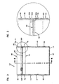
- FIG. 1 a flexible, reclosable package 10 having side panels 12 and 14.
- a surrounding wall 11, formed by side panels 12, 14, defines a package interior 21, shown in FIGS. 4 and 5 .
- Package 10 has side edges 13, 15 and a bottom edge 17, which, with side panels 12, 14, define interior 21.
- a zipper closure 20, having closure profiles to open and close (unseal and reseal) package 10, provides access to interior 21 through a mouth 30.
- Zipper closure 20 can include a variety of configurations and structures.
- zipper closure 20 can be constructed according to PCT Published Application WO 00/22851 .
- Zipper closure 20 has a first closure profile 22 and a second closure profile 24 that mate and unmate, interlock and unlock, engage and disengage, as appropriate, to open and close mouth 30.
- First closure profile 22 includes a first mating member 32 with a distal end 26, a first shoulder 36, and a sealing flange 37; second closure profile 24 includes a second mating member 34 with a distal end 28, a second shoulder 38, and a sealing flange 39. First mating member 32 engages and disengages with second mating member 34.
- a slider device 50 is mounted on zipper closure 20 to facilitate opening and closing of zipper closure 20.
- slider device 50 is positioned to allow access through mouth 30; that is, package 10 can be considered "open".
- Slider device 50 is positioned over distal ends 26, 28 and is held onto zipper closure 20 by shoulders 36, 38 of first and second closure profiles 22, 24.
- Slider devices and how they function to open and close zipper closures; in general, are taught, for example, in U.S. Patent Nos. 5,063,644 ; 5,301,394 ; and 5,442,837 .
- Preferred slider device are taught in PCT Published Application WO 00/22851 , U.S. Design Patent No. 434,345 , U.S. and U.S.
- slider device 50 is preferably constructed and arranged in accordance with the disclosures of PCT Published Application WO 00/22851 , U.S. Design Patent No. 434,345 , and patent application 09/918,982 .
- a notch 25 is present within zipper closure 20 adjacent to first side edge 13 in the package 10.
- Notch 25 is designed to provide a "park place” into which slider device 50 settles when zipper closure 20 is sealed and slider device 50 is at first edge 13.
- Such a notch 25 may decrease any tendency for an incomplete interlock between first closure profile 22 and second closure profile 24.
- Package 10 is shown in FIG. 1 without a tamper-evident structure positioned over or encasing slider device 50.
- a package 10' is similar to that of package 10 of FIG. 1 , except that package 10' has a tamper-evident structure 60 positioned over and encasing zipper closure 20 and slider device 50. Additionally, package 10' has a second tamper-evident structure 70 positioned between zipper closure 20 and interior 21 1 of package 10'.
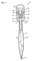
- Package 10' is shown in cross-section in FIG. 4 . Additional details of package 10' are also shown in FIGS. 2 and 4 , when compared to package 10 of FIG. 1 .
- first tamper evident-structure 60 surrounds, covers, encases, and otherwise protects first and second closure profiles 22, 24 so that the profiles cannot be separated without penetrating tamper evident-structure 60.
- First tamper-evident structure 60 also covers slider device 50, which is mounted on closure profiles 22, 24.
- First tamper evident-structure 60 is considered an "external" tamper evident-structure because it is positioned external to zipper closure 20 in relation to the package interior 21.
- First tamper evident-structure 60 is not a structure that is _ commonly referred to as a "peel seal"; rather, tamper evident-structure 60 is a structure such as a membrane, film, web, or the like that extends from panels 12, 14 and covers distal ends 26, 28 of zipper closure 20 and slider device 50.
- First tamper-evident structure 60 is typically formed from extensions of panels 12, 14 that are positioned over zipper closure 20; these extensions of panels 12, 14 may be two unconnected ends of panels 12, 14 or may be formed by a crease or fold between connected panels 12, 14. In other embodiments, tamper-evident structure 60 can be made from a separate web folded over and attached to panels 12, 14.
- first tamper evident-structure 60 is penetrated by removing tamper evident-structure 60, which is preferably done at a weakness 62.
- Weakness 62 can be a perforation, tear-strip, zip-strip, die line, laser score line, or any mechanism or structure that allows for easy penetration.
- Weakness 62 is positioned below zipper closure 20; that is weakness 62 is positioned between zipper closure 20 and bottom edge 17 of the package.
- weakness 62 is positioned below slider device 50.
- First tamper-evident structure 60 generally extends from the top of the package, that is, the portion of the package farthest from bottom edge 17, to weakness 62. Specific details regarding one method for making a package having tamper-evident structure 60 are provided below.
- Package 10' shown also includes a second tamper evident-structure 70 that extends between sealing flanges 37, 39 of closure profiles 22, 24.
- Second tamper evident-structure 70 is considered an "internal" tamper evident-structure because it is positioned between zipper closure 20 and the package interior 21. Even after closure profiles 22, 24 have been opened and separated, access cannot be gained to interior 21 without penetrating second tamper-evident structure 70.
- second tamper evident-structure 70 could also be a structure commonly referred to as a "peel seal”. If tamper-evident structure 70 is a peel seal or a peelable seal, this seal may be a single use seal or a multiple use seal.
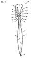
- FIG. 5 shows a package 10", a variation of the package having first and second tamper-evident structures.
- Package 10 is similar to package 10' except that package 10" has first tamper-evident structure 60 external to zipper closure 20 but no second tamper-evident structure internal to zipper closure 20. Tamper-evident structure 60 is the only tamper-evident structure present on package 10". Both packages, package 10' and package 10" can be made by the methods of the present disclosure, described below.
- Package 10' has interior 21 defined by first side edge 13, second side edge 15 and bottom edge 17. Each of these edges, 13, 15, 17 has a seal or seam, created by the attachment of panels 12, 14 together. Typically, this sealing is done by the application of heat, under pressure, to at least one panel when in contact with the other panel.
- first side edge 13 is a first side body seam 53
- second side edge 15 is a second side body seam 55
- bottom edge 17 is a bottom seam 57.
- First and second side body seams 53, 55 extend from bottom edge 17 to zipper closure 20, but do not extend over zipper closure 20; preferably side body seams 53, 55 do not contact zipper closure 20.
- First tamper-evident structure 60 includes first tamper-evident structure seams 63, 65, located at side edges 13, 15, respectively; first tamper-evident structure seams 63, 65 close the ends of tamper-evident structure 60 at side edges 13, 15 so that access cannot be gained to zipper closure 20 through edges 13, 15.
- First tamper-evident structure seams 63, 65 are also typically made by the application of heat and pressure to the film panels that form tamper-evident structure 60.
- First tamper-evident structure seams 63, 65 extend from the top of tamper-evident structure 60 to zipper closure 20, but do not contact or extend over zipper closure 20.
- side body seams 53, 55 include second tamper-evident structure seams 73, 75.
- Second tamper-evident structure seams 73, 75 are seals or seams at edges 13, 15 that are formed where panels 12, 14 and second tamper-evident structure 70 are sealed together, typically by the application of heat and pressure.
- side edges 13, 15 include a non-seam section 230, 250, respectively.
- Non-seam sections 230, 250 are void of side seams.
- zipper closure 20 which includes closure profiles 22, 24, including base members 32, 34, distal ends 26, 28, and at least a portion of sealing flanges 37, 39. In other words, the intersection of zipper closure 20 and side edges 13, 15 is void of side seams.
- non-seam sections 230, 250 are void of seams or seals created by the application of heat and pressure provided by seal bars used to provide the seams 53, 55, 63, 65.
- Non-seam sections 230, 250 allow for easy removal of tamper-evident structure 60 by minimizing, and preferably eliminating, any attachment of tamper-evident structure 60 to zipper closure 20.
- Non-seam sections 230, 250 typically extend from distal ends 26, 28 of zipper closure 20 to at least, and preferably below, weakness 62.
- weakness 62 By use of the term “below”, what is meant is that non-seam sections 230, 250 extend between weakness 62 and bottom edge 17.
- zipper closure 20 has seal resistant portions with one seal resistant portion located at side edge 13 of the package ( FIG. 4 ) and the other seal resistant portion located at side edge 15 of the package ( FIG. 3 ). These seal resistance portions are constructed to not readily seal to panels 12, 14; that is, during the process of sealing side seams 53, 55 and first tamper-evident structure seams 63, 65 with heat and pressure, the seal resistant portions do not readily form a seam with or seal to panels 12, 14.
- Zipper closure 20, within each seal resistant portion is, however, capable of sealing to itself during an ultrasonic welding process, as will be described below; that is, first closure profile 22 can be attached to second closure profile 24, but neither profile 22, 24 readily seals to panels 12, 14.
- the seal resistant portions include distal ends 26, 28, base members 32, 34, and the portion of sealing flanges 37, 39 that is positioned above weakness 62.
- each seal resistant portion includes a portion of sealing flange 37, 39 located below weakness 62, however, the amount of sealing flange 37, 39 present within the seal resistant portions should not be so large that sealing flanges 37, 39 do not adequately seal to panels 12, 14.
- the seal resistant portions can be made from a different material than panels 12, 14, preferably from a material having a higher melting point temperature than panels 12, 14; this allows seams 53, 55, 63, 65 to be made without melting or distorting zipper closure 20 and without adhering panels 12, 14 to zipper closure 10.
- the seal resistant portions can be made from a material that is incompatible with panels 12, 14.
- zipper closure 20 can include a high temperature additive or surface coating or a surface wax that inhibits adhesion between zipper closure 20 and panels 12, 14. Any of these various options can be incorporated into zipper closure 20 as a post-treatment or can be co-extruded with zipper closure 20.
- non-seam sections 230, 250 are present in non-seam sections 230, 250, respectively; it is the seal resistant portions that provide non-seam sections 230, 250.
- non--seam sections 230, 250 may be larger and occupy more length of sides 13, 15 than the seal resistant portions.
- non-seam sections 230, 250 are void of side seams, and instead, include a slider stop region 223, 225.
- Slider stop regions 223, 225 preferably include areas where closure profiles 22, 24 are sealed together; slider stop regions 223, 225 retain slider device 50 on zipper closure 20.
- the portions of closure profiles 22, 24 that are sealed can include distal ends 26, 28, mating members 32, 34, and at least a portion of sealing flanges 37, 39.
- Slider stop regions 223, 225 are typically ultrasonioally welded or otherwise crushed. The crushing results in a mass of plastic (polymeric) material melted or otherwise joined together.
- slider stop regions 223, 225 are shown in FIGS. 2 and 3 as angled, almost triangular areas.
- slider stop region 223, 225 may intersect with either or both of first tamper-evident structure side seam 63, 65 and side body seam 53, 55.
- slider stop region 225 intersects with side body seam 55 to form overlap region 252.
- first tamper-evident structure 60 and second tamper-evident structure 70 need to be penetrated.
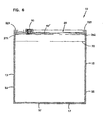
- package 10' from FIGS. 2, 3 and 4 is now shown as package 10, having first tamper-evident structure 60 removed and thus allowing access to zipper closure 20 and slider device 50.
- First tamper-evident structure 60 was removed at weakness 62, thus leaving edge 62' on package 10.
- Package 10 of FIG. 6 shows various features also shown in FIG. 2 , such as side seams 53, 55 at side edges 13, 15, bottom seam 57 at bottom edge 17, slider stop regions 223, 225, and overlap regions 232, 252 where slider stop regions 223, 225 intersect with side seams 53,55.
- Packages according to the present disclosure can be made by the following procedure, which is described referring to FIGS. 7 through 10 .
- slider device 50 is mounted onto zipper closure 20 prior to connecting zipper closure to panels 12, 14.
- zipper closure 20 includes slider device 50, notch 25, and slider stop regions 223, 225 prior to connecting the zipper closure to panels 12, 14.
- the preferred zipper construction 201, having slider device 50, notch 25, and slider stop regions 223, 225 (shown as one region 224) on extended length of zipper closure 200 is shown in FIG. 8 . If no slider device is present, the zipper construction will merely include extended length of zipper closure 200 and region 224.
- Extended length of zipper closure 200 is provided on spool 205.
- Extended length of zipper closure 200 can be made by any suitable method, but is typically extruded.
- First and second closure profiles 22, 24 can be extruded individually, that is, as two individual profiles, or, closure profiles 22, 24 can be extruded connected at either distal ends 26, 28 or at sealing flanges 37, 39. If closure profiles 22, 24 are connected at their distal ends 26, 28, the two profiles 22, 24 are slit or otherwise separated before mounting slider device 50 onto extended length of zipper closure 200. If closure profiles 22, 24 are connected at the sealing flanges 37, 39, the two profiles 22, 24 may or may not be separated. If not separated but left connected, the web connecting sealing flanges 37, 39 provides tamper-evident structure 70.
- extended length of zipper closure 200 is provided via spool 205.
- zipper closure 20 may be extruded, cast or otherwise formed immediately before this process, thereby eliminating the step of winding extended length of zipper closure 200 onto spool 205 after forming the zipper closure 20 and then unwinding when slider devices 50 are mounted.
- First and second closure profiles 22, 24 may be interlocked (mated) or unmated while retained on spool 205. If closure profiles 22, 24 are unmated, in some embodiments it may be desired to have first closure profile 22 on a first spool and second closure profile 24 on a second spool. It should be noted, that interlocked profiles can be unmated as desired, and unmated profiles can be mated as desired. In most embodiments, it is desired that profiles 22, 24 are mated.
- Zipper closure 20 is unwound from spool 205 and fed to slider mounting system 100. Any zipper drive unit or tensioning unit can be provided to control the winding of zipper closure 20 from spool 205. At slider mounting system 100, zipper closure 20 undergoes various processes, including having slider device 50, if present, mounted thereon.
- Slider device 50 is fed by a slider source such as bowl feeder 150, which properly orients slider device 50 for mounting onto distal ends 26, 28 of zipper closure 20.
- bowl feeder 150 is positioned on a table or other support 110. Slider devices 50 progress from bowl feeder 150 along feed track 152 to slider mounting system 100.
- slider device 50 can be fed to slider mounting system 100 by multiple bowl feeders feeding a single track 152, a vibratory feeder, a spool of slider devices adhered to or carried on or by a carrier tape, a connected chain of slider devices, be manually fed, or by any other process that can provide a continuous supply of slider devices to slider mounting system 100. Gravity, an air stream, and other methods can be used to facilitate feeding of the slider devices.
- a multi-channeled bowl feeder is used to orientate slider devices 50 to the proper position for application to zipper closure 20 by slider mounting system 100.
- Slider mounting system 100 supported by table 110, has extended length of zipper closure 200 passing therethrough.
- Table 110 can include a registration system for providing fine tuning of spacing and positioning, as needed, of slider mounting system 100.
- Slider mounting system 100 can include a slider notch punch unit 140, a profile clamping unit 120, a slider installation mechanism 130, and a slider stop seal unit 160.
- the various features of slider mounting system 100 provide the following functions: profile clamp 120 securely holds zipper closure 20 during the various operations; slider installation mechanism 130 mounts slider device 50 onto zipper closure 20; punch unit 140 provides notch 25; and stop seal unit 160 forms slider stop regions 223, 225.
- Slider mounting system 100 is designed to have each of these various units (i.e., punch unit 140, profile clamp 120, slider installation mechanism 130, and slider stop seal unit 160) function together, in essence simultaneously, to provide an extended length of zipper closure 200 processed and ready to be incorporated into a package.
- Extended length of zipper closure 200 is incrementally indexed through slider mounting system 100, so that the processed zipper closure 20 has repeating features, that is, slider device 50, slider stop regions 223, 225, and notch 25.
- Profile clamp 120 secures zipper closure 20 during the time the various procedures of slider mounting system 100 are performed on zipper closure 20.
- Profile clamp 120 can be any mechanism that can securely hold zipper closure 20; such mechanisms can include hinged clamps, arms, fingers, or any such items.
- Profile clamp 120 can hold each of first and second closure profiles 22, 24 individually, or can hold profiles 22, 24 with a single mechanism or surface. In some embodiments, it is preferred that profile clamp 120 has two opposed portions between which the zipper closure 20 is retained. Further, it is preferred that the surfaces of profile clamp 120 that contact zipper closure 20 are at least somewhat contoured to the profile zipper closure 20, so that the clamping pressure is fairly evenly distributed across first closure profile 22 and second closure profile 24.
- Punch unit 140 provides notch 25 to zipper closure 20.
- Punch unit 140 may be a die, knife, stamp or other such process, and may be hydraulic or pneumatic.
- the small piece of polymeric material removed by punch unit 140 (herein referred to as a "slug") that defines notch 25 may be removed from the area of punch unit 140 by an air blast or by vacuum.
- Slider device 50 is applied to zipper closure 20 by slider installation mechanism 130, which can be any device or method for applying slider device 50 onto zipper closure 20. Generally, if closure profiles 22, 24 are mated, slider device 50 typically is applied at notch 25; if closure profiles 22, 24 are unmated, slider device 50 typically is applied at the opposite end of zipper closure 20, for example, close to slider stop region 225.
- Slider stop seal unit 160 forms slider stop regions 223, 225. These regions 223, 225 are areas where closure profiles 22, 24 have been sealed together, typically by ultrasonic welding. In FIG. 8 , slider stop regions 223, 225 are shown as a single region 224.
- resealable, reclosable packages can be manufactured by various methods, such as a horizontal form, fill and seal process.
- the package is manufactured, filled, and sealed by a single process that includes multiple sequential steps.
- FIG. 9 a horizontal form, fill and seal process is shown. As illustrated in FIG. 9 , the process line progresses from right to left so that the final filled package is at the left side of the figure. Generally with a horizontal form, fill and seal process, the package can be manufactured upside-down so that the filling takes place through the bottom of the package, or, the package can be manufactured mouth-side up so that filling takes place through the top of the package. Throughout this disclosure, the edge of the package having the mouth 30 ( FIG. 1 ) and the zipper closure 20 will be referred to as the "top" of the package. The edges of the package having bottom edge 17 is referred to as the "bottom" of the package. The process depicted in FIG. 9 shows the packages filled through the bottom of the package.
- polymeric film 300 which will provide panels 12, 14 of surrounding wall 11 of the package, is provided on roll 305.
- film 300 may be extruded, cast or otherwise formed immediately prior to this horizontal form, fill and seal process, thereby eliminating the step of winding the film after forming the film and then unwinding the film when the packages are made.
- the width of polymeric film 300, from first edge 300a to second edge 300b, is approximately twice the distance between bottom edge 17 ( FIG. 1 ) and the top of tamper-evident structure 60 of the finished package.
- Various tensioners, idlers, rollers, positioners, and the like can be used to help control the position and tension of film 300.
- film 300 is provided with weakness 62 ( FIGS. 2 and 3 ).
- Equipment 362 is used to provide weakness 62; equipment 362 can be any equipment suited to provide weakness 62; examples of possible equipment includes a perforator, a laser, or other item that can provide the desired weakness.
- Film 300 is folded to provide first and second film halves 112, 114 which will provide first and second side panels 12, 14 of the resulting package. This folding can be done by conventional methods, such as a V-board 310 or various rollers. In another embodiment, two separate pieces of film 300 can be used, one for each of side panels 12, 14; it is noted that if two separated pieces of film are used, then in order to form tamper-evident structure 60, the two pieces will be sealed together. The fold or seal between film halves 112, 114 forms tamper-evident structure 60.
- a slitter knife 320 close to the base of the V-board 310 slits film 300, making an opening for passing zipper construction 201 therethrough.
- the extended length of zipper construction 201 is fed between the two film halves 112, 114 oriented so that distal ends 26, 28 are directed to the fold between film halves 112, 114.
- Guides, fingers, bars, rollers, or anything of the like may be used to manipulate either or both of film halves 112, 114 and extended length of zipper construction 201 to provide proper placement of zipper construction 201.
- Heated rollers 330 may be used to seal or preseal extended length of zipper closure 201 to film halves 112, 114.
- Seal bars 340 provide vertical seals across the width of the folded film and zipper closure combination. These vertical seals will eventually result in side body seams 53, 55 and first tamper-evident structure seams 63, 65 of package 10, 10'. Between each side body seam formed by seal bars 340 is one slider device 50 and one notch 25; region 224 ( FIG. 8 ) is split by seal bars 340 to form slider stop regions 223, 225. Seal bar 340 is shown enlarged in FIG. 10 .
- Seal bar 340 has a body sealing surface 350 and a first tamper-evident structure sealing surface 360, which are generally coplanar and both which can be heated to form seams.
- Body sealing surface 350 provides body seams 53, 55
- first tamper-evident structure sealing surface 360 provides first tamper-evident structure seams 63, 65.
- Seal bar 340 includes surface 355 that aligns with zipper closure 20 to form non-seam sections 230, 250, the areas void of side seams.
- Surface 355 is recessed in relation to surfaces 350, 360, so that surface 355 does not contact zipper construction 201 or film 300. However, if surface 355 were to contact zipper construction 201, zipper closure 20 has that portion that is constructed to not readily seal to panels 12, 14.
- Surface 355 is preferably not heated.
- one seal bar 340 is positioned on each side of the film 300 and zipper closure 201.
- Heat can be provided from one or both sides of the film; additionally or alternatively, the temperature from one side to another can be the same or can be different.
- Multiple seal bars 340, such as shown in FIG. 9 can be heated to different temperatures. The process can be designed so that each seam area is contacted by multiple seal bars, or by only one bar.
- seal bar 370 can be used to securely seal zipper construction 201 to film halves 112, 114.
- the resulting package, semi-finished because bottom edge 17 has not yet been sealed, can be filled with items or material from hopper 380.
- the semi-finished package can be provided to a packaging facility, which will fill and complete the packages. Once filled, seal bar 390 forms bottom seam 57, and cutting bar 400 separates individual packages 10'.
- tamper evident-structure 60 To use the resulting package, such as package 10' ( FIG. 2 ), tamper evident-structure 60, and, if present, tamper-evident structure 70 must be penetrated in order to access interior 21 of package 10'.
- First tamper evident-structure 60 is removed from over zipper closure 20 at weakness 62, which is positioned below zipper closure 20.
- the presence of non-seam sections 230, 250 facilitates removal of tamper-evident structure 60, because tamper-evident structure 60 is not adhered to zipper closure 20. Rather, the material forming tamper-evident structure 60 is generally only attached to panels 12, 14 at weakness 62, thus, breaking weakness 62 releases tamper-evident structure 60.
- Non-seam sections 230, 250 are generally removed from the package along with tamper-evident structure 60.
- first and second closure profiles 22, 24 of zipper closure 20 are unmated to open mouth 30; this action is facilitated by slider device 50, if present.
- second tamper-evident structure 70 is present, in order to access interior 21, second tamper evident-structure 70 must be penetrated.
- second tamper evident-structure 70 is penetrated by breaking a weakness present therein. This weakness can be a perforation, zip-strip, a die line, laser score line or any mechanism or structure that allows for easy penetration.
- interior 21 is accessible.
Landscapes
- Engineering & Computer Science (AREA)
- Mechanical Engineering (AREA)
- Making Paper Articles (AREA)
- Bag Frames (AREA)
Abstract
Description
- This disclosure concerns re-closable packages. In particular, this disclosure describes re-closable packages having slider devices for opening and closing the packages, and methods of manufacturing the packages.
- Flexible packages, in particular re-sealable and re-closable packages, are frequently used for packaging of consumable goods (
US A 4 658 433 ). Goods that are not used completely when the package is initially opened rely on a zipper closure to re-close the package and keep the remaining contents-fresh. Examples of consumable goods that are often packaged in packages, such as bags, with a zipper closure include potting soil, fertilizer, socks, pet food, dog biscuits, vegetables, cereal, and many different foods edible by humans. - Often, the opening and closing of the zipper closure is facilitated by a slider device that is mounted on the zipper closure (
EP-A-1 251 075 ). The slider device is constructed to pry apart the interlocking zipper closure members when the slider device is moved in a first direction along the zipper, and to engage the interlocking zipper closure members when the slider device is moved in a second, opposite direction along the zipper. For some applications, a tamper-evident structure, to notify whether access has been gained to the zipper closure, is desired. Improvements in these types of packages are desirable. - According to one aspect, the present invention provides a method of manufacturing a flexible re-closable package in accordance with Claim 1 of the claims.
- According to another aspect of the invention, there is provided a flexible re-closable package according to
Claim 11. - The present disclosure describes a method of manufacturing a package such as a flexible bag having a re-sealable re-closable zipper mechanism or closure.
- The present disclosure describes a method of manufacturing a package, such as a flexible bag, having a re-sealable, re-closable zipper mechanism or closure. In preferred embodiments, the package interior is defined by panels having a bottom edge and first and second side edges the side edges having seams formed by a sealing process. The seam at each of the first and second side edges does not extend the entire length of the side edge; rather, the intersection of the zipper closure with the side edge is not sealed. The zipper closure has stop areas, positioned proximate the side edges, which include seal resistant portions. The seal resistant portions do not readily seal to the panels.
- In one embodiment, the present disclosure is directed to form, fill and seal processes that manufactures flexible packages having a reclosable zipper closure, fills the packages with items, and seals the filled packages. The form, fill, and seal process can be a horizontal process.
- In one particular embodiment, the present disclosure is directed to a method of making a resealable, reclosable package. The method includes providing an extended length of a zipper construction, which includes a zipper closure having stop areas present therein, sealing the extended length of zipper construction to a surrounding wall, creating an external tamper-evident structure, and forming edges in the surrounding wall to form a package interior. The edges formed are defined by body seams, a bottom seam, tamper-evident structure seams, and non-seam area. The resulting package interior may be filled prior to forming all of the seams.
- In another particular embodiment, the present disclosure is directed to a method of manufacturing a reclosable package comprising a zipper closure. The method comprises providing an extended length of a zipper construction, sealing the extended length of the zipper construction to a surrounding wall, sealing the surrounding wall to partially define a package interior, and creating a bottom seam. The zipper construction comprises a zipper closure comprising a first closure profile and a second closure profile, the first and second closure profiles being constructed and arranged to selectively interlock, and a stop region connecting the first closure profile to the second closure profile. The step of sealing the surrounding wall to partially define a package interior includes providing side body seams extending along a portion of the surrounding wall and providing non-seam sections along the slider stop region. The bottom seam and the side body seams defining the package interior.
- In one embodiment, a resealable, reclosable package has a surrounding wall defining a package interior and a zipper closure and slider device for providing access to the package interior.
- In one particular embodiment of this disclosure, a flexible, reclosable package is provided. The package comprises a surrounding wall defining a package interior, the surrounding wall being defined by a bottom edge and side edges, with side edges comprising a body seam, a tamper-evident structure seam, and a non-seam section. The package further has a zipper closure and a tamper-evident structure. The zipper closure comprises a first closure profile and a second closure profile, the first and second closure profiles constructed and arranged to selectively interlock, the zipper closure having first and second stop regions proximate the non-seam section, and the zipper closure providing access to the package interior.
-
-
FIG. 1 is a perspective view of a flexible, reclosable package; -
FIG. 2 is a partially schematic, front plan view of a flexible, reclosable package having a tamper-evident structure according to the present disclosure; -
FIG. 3 is an enlarged, partial view of one side edge of the flexible, reclosable package ofFIG. 2 ; -
FIG. 4 is a schematic, cross-sectional view of the package taken along line 4-4 ofFIG. 3 ; -
FIG. 5 is a schematic, cross-sectional view of a second embodiment of a package according to the present disclosure, similar to the package ofFIG. 4 ; -
FIG. 6 is a partially schematic, front plan view of the flexible, reclosable package ofFIG. 2 according to the present disclosure having the tamper-evident structure removed; -
FIG. 7 is a schematic, perspective view of a process for mounting a slider device onto an extended length of zipper closure; -
FIG. 8 is a schematic view of an extended length of zipper closure having a slider device mounted thereon; -
FIG. 9 is a schematic, perspective view of a horizontal form, fill, and seal process for manufacturing and filling packages using an extended length of the zipper closure ofFIG. 8 ; and -
FIG. 10 is a schematic, side view of a vertical sealing bar of the process ofFIG. 9 . - The addition of a slider device to a flexible package, such as a plastic bag, is advantageous to aging or arthritic persons not having the physical ability to use just a zipper closure to reseal a bag. Additionally, the addition of a tamper-evident structure to the package is advantageous to notifying whether tampering has occurred to the package. The package of the present disclosure includes a slider device to open and close the package, and a first tamper-evident structure to indicate whether access has been gained to the zipper closure and slider device. The package of the present disclosure may include a second tamper-evident structure to indicate whether access has been gained to the interior of the package.
- Referring to the figures, wherein like numerals represent like parts throughout the several views, there is schematically illustrated in
FIG. 1 a flexible,reclosable package 10 havingside panels wall 11, formed byside panels package interior 21, shown inFIGS. 4 and5 .Package 10 hasside edges bottom edge 17, which, withside panels interior 21. Azipper closure 20, having closure profiles to open and close (unseal and reseal)package 10, provides access tointerior 21 through amouth 30.Zipper closure 20 can include a variety of configurations and structures. For example,zipper closure 20 can be constructed according toPCT Published Application WO 00/22851 Zipper closure 20 has afirst closure profile 22 and asecond closure profile 24 that mate and unmate, interlock and unlock, engage and disengage, as appropriate, to open and closemouth 30. -
Zipper closure 20 is shown in detail inFIGS. 4 and5 .First closure profile 22 includes afirst mating member 32 with adistal end 26, afirst shoulder 36, and asealing flange 37;second closure profile 24 includes asecond mating member 34 with adistal end 28, asecond shoulder 38, and asealing flange 39.First mating member 32 engages and disengages withsecond mating member 34. - Preferably, a
slider device 50 is mounted onzipper closure 20 to facilitate opening and closing ofzipper closure 20. InFIG. 1 ,slider device 50 is positioned to allow access throughmouth 30; that is,package 10 can be considered "open".Slider device 50 is positioned over distal ends 26, 28 and is held ontozipper closure 20 byshoulders U.S. Patent Nos. 5,063,644 ;5,301,394 ; and5,442,837 . Preferred slider device are taught inPCT Published Application WO 00/22851 U.S. Design Patent No. 434,345 , U.S. andU.S. patent application 09/918,982 filed July 31, 2001 FIGS. 1 ,4 and5 ,slider device 50 is preferably constructed and arranged in accordance with the disclosures ofPCT Published Application WO 00/22851 U.S. Design Patent No. 434,345 , and patent application09/918,982 - Referring again to the embodiment shown in
FIG. 1 , anotch 25 is present withinzipper closure 20 adjacent tofirst side edge 13 in thepackage 10.Notch 25 is designed to provide a "park place" into whichslider device 50 settles whenzipper closure 20 is sealed andslider device 50 is atfirst edge 13. Such anotch 25 may decrease any tendency for an incomplete interlock betweenfirst closure profile 22 andsecond closure profile 24. -
Package 10 is shown inFIG. 1 without a tamper-evident structure positioned over or encasingslider device 50. InFIG. 2 , a package 10' is similar to that ofpackage 10 ofFIG. 1 , except that package 10' has a tamper-evident structure 60 positioned over and encasingzipper closure 20 andslider device 50. Additionally, package 10' has a second tamper-evident structure 70 positioned betweenzipper closure 20 and interior 21 1 of package 10'. Package 10' is shown in cross-section inFIG. 4 . Additional details of package 10' are also shown inFIGS. 2 and4 , when compared to package 10 ofFIG. 1 . - Referring to
FIGS. 2 and4 , first tamper evident-structure 60 surrounds, covers, encases, and otherwise protects first and second closure profiles 22, 24 so that the profiles cannot be separated without penetrating tamper evident-structure 60. First tamper-evident structure 60 also coversslider device 50, which is mounted on closure profiles 22, 24. First tamper evident-structure 60 is considered an "external" tamper evident-structure because it is positioned external tozipper closure 20 in relation to thepackage interior 21. First tamper evident-structure 60 is not a structure that is _ commonly referred to as a "peel seal"; rather, tamper evident-structure 60 is a structure such as a membrane, film, web, or the like that extends frompanels zipper closure 20 andslider device 50. First tamper-evident structure 60 is typically formed from extensions ofpanels zipper closure 20; these extensions ofpanels panels connected panels evident structure 60 can be made from a separate web folded over and attached topanels - To gain access to
zipper closure 20, first tamper evident-structure 60 is penetrated by removing tamper evident-structure 60, which is preferably done at aweakness 62.Weakness 62 can be a perforation, tear-strip, zip-strip, die line, laser score line, or any mechanism or structure that allows for easy penetration.Weakness 62 is positioned belowzipper closure 20; that isweakness 62 is positioned betweenzipper closure 20 andbottom edge 17 of the package. Similarly and preferably,weakness 62 is positioned belowslider device 50. First tamper-evident structure 60 generally extends from the top of the package, that is, the portion of the package farthest frombottom edge 17, toweakness 62. Specific details regarding one method for making a package having tamper-evident structure 60 are provided below. - Package 10' shown also includes a second tamper evident-
structure 70 that extends between sealingflanges structure 70 is considered an "internal" tamper evident-structure because it is positioned betweenzipper closure 20 and thepackage interior 21. Even after closure profiles 22, 24 have been opened and separated, access cannot be gained tointerior 21 without penetrating second tamper-evident structure 70. Although shown as a structure such as a membrane, film, web, or the like that provides a discernible length of distance between sealing flanges, 37, 39, second tamper evident-structure 70 could also be a structure commonly referred to as a "peel seal". If tamper-evident structure 70 is a peel seal or a peelable seal, this seal may be a single use seal or a multiple use seal. -
FIG. 5 shows apackage 10", a variation of the package having first and second tamper-evident structures.Package 10" is similar to package 10' except thatpackage 10" has first tamper-evident structure 60 external tozipper closure 20 but no second tamper-evident structure internal tozipper closure 20. Tamper-evident structure 60 is the only tamper-evident structure present onpackage 10". Both packages, package 10' andpackage 10" can be made by the methods of the present disclosure, described below. - Referring again to
FIG. 2 and toFIG. 3 , various features of the packages made by the process of the present disclosure will be described. Package 10' has interior 21 defined byfirst side edge 13,second side edge 15 andbottom edge 17. Each of these edges, 13, 15, 17 has a seal or seam, created by the attachment ofpanels first side edge 13 is a firstside body seam 53, atsecond side edge 15 is a secondside body seam 55, and atbottom edge 17 is abottom seam 57. First and second side body seams 53, 55 extend frombottom edge 17 tozipper closure 20, but do not extend overzipper closure 20; preferably side body seams 53, 55 do not contactzipper closure 20. - First tamper-
evident structure 60 includes first tamper-evident structure seams 63, 65, located at side edges 13, 15, respectively; first tamper-evident structure seams 63, 65 close the ends of tamper-evident structure 60 at side edges 13, 15 so that access cannot be gained tozipper closure 20 throughedges evident structure 60. First tamper-evident structure seams 63, 65 extend from the top of tamper-evident structure 60 tozipper closure 20, but do not contact or extend overzipper closure 20. - If second tamper-
evident structure 70 is present in the package, side body seams 53, 55 include second tamper-evident structure seams 73, 75. Second tamper-evident structure seams 73, 75 are seals or seams at edges 13, 15 that are formed wherepanels evident structure 70 are sealed together, typically by the application of heat and pressure. - Because neither side body seams 53, 55, first tamper-evident structure seams 63, 65, nor second tamper-evident structure seams 73, 75 are present at, extend over, or
contact zipper closure 20, side edges 13, 15 include anon-seam section Non-seam sections non-seam sections zipper closure 20, which includes closure profiles 22, 24, includingbase members flanges zipper closure 20 and side edges 13, 15 is void of side seams. By use of the term "void of side seams", it is not intended to mean that there are no areas or spots of material sealed together in that area; rather, it is intended that there is no seam formed betweenpanels zipper closure 20. Generally, no seam is formed betweenzipper closure 20 andpanels zipper closure 20 has been brought into contact withpanels non-seam sections seams -
Non-seam sections evident structure 60 by minimizing, and preferably eliminating, any attachment of tamper-evident structure 60 tozipper closure 20.Non-seam sections distal ends zipper closure 20 to at least, and preferably below,weakness 62. By use of the term "below", what is meant is thatnon-seam sections weakness 62 andbottom edge 17. By having generally no portion of tamper-evident structure 60 aboveweakness 62 attached tozipper closure 20, tamper-evident structure 60 can be easily removed. - To facilitate the forming of
non-seam sections zipper closure 20 has seal resistant portions with one seal resistant portion located atside edge 13 of the package (FIG. 4 ) and the other seal resistant portion located atside edge 15 of the package (FIG. 3 ). These seal resistance portions are constructed to not readily seal topanels panels Zipper closure 20, within each seal resistant portion is, however, capable of sealing to itself during an ultrasonic welding process, as will be described below; that is,first closure profile 22 can be attached tosecond closure profile 24, but neitherprofile panels base members flanges weakness 62. Typically, each seal resistant portion includes a portion of sealingflange weakness 62, however, the amount of sealingflange flanges panels - The seal resistant portions can be made from a different material than
panels panels zipper closure 20 and without adheringpanels zipper closure 10. Alternately, The seal resistant portions can be made from a material that is incompatible withpanels zipper closure 20 can include a high temperature additive or surface coating or a surface wax that inhibits adhesion betweenzipper closure 20 andpanels zipper closure 20 as a post-treatment or can be co-extruded withzipper closure 20. - The seal resistant portions are present in
non-seam sections non-seam sections seam sections sides - As stated above,
non-seam sections slider stop region Slider stop regions slider stop regions retain slider device 50 onzipper closure 20. The portions of closure profiles 22, 24 that are sealed can include distal ends 26, 28,mating members flanges Slider stop regions slider stop regions FIGS. 2 and 3 as angled, almost triangular areas. - A portion of
slider stop region structure side seam side body seam FIG. 3 ,slider stop region 225 intersects withside body seam 55 to formoverlap region 252. - As stated above, in order to gain access to any items within the interior of the package, first tamper-
evident structure 60 and second tamper-evident structure 70, if present, need to be penetrated. InFIG. 6 , package 10' fromFIGS. 2, 3 and4 is now shown aspackage 10, having first tamper-evident structure 60 removed and thus allowing access tozipper closure 20 andslider device 50. First tamper-evident structure 60 was removed atweakness 62, thus leaving edge 62' onpackage 10.Package 10 ofFIG. 6 shows various features also shown inFIG. 2 , such as side seams 53, 55 at side edges 13, 15,bottom seam 57 atbottom edge 17,slider stop regions regions regions side seams - Packages according to the present disclosure can be made by the following procedure, which is described referring to
FIGS. 7 through 10 . - In a preferred method of making a package having a slider device,
slider device 50 is mounted ontozipper closure 20 prior to connecting zipper closure topanels zipper closure 20 includesslider device 50,notch 25, and slider stopregions panels preferred zipper construction 201, havingslider device 50,notch 25, and slider stopregions 223, 225 (shown as one region 224) on extended length ofzipper closure 200 is shown inFIG. 8 . If no slider device is present, the zipper construction will merely include extended length ofzipper closure 200 andregion 224. - To provide
zipper construction 201 as shown, an extended length ofzipper closure 200 is provided onspool 205. Extended length ofzipper closure 200 can be made by any suitable method, but is typically extruded. First and second closure profiles 22, 24 can be extruded individually, that is, as two individual profiles, or, closure profiles 22, 24 can be extruded connected at either distal ends 26, 28 or at sealingflanges distal ends profiles slider device 50 onto extended length ofzipper closure 200. If closure profiles 22, 24 are connected at the sealingflanges profiles flanges evident structure 70. - As mentioned, extended length of
zipper closure 200 is provided viaspool 205. In another embodiment,zipper closure 20 may be extruded, cast or otherwise formed immediately before this process, thereby eliminating the step of winding extended length ofzipper closure 200 ontospool 205 after forming thezipper closure 20 and then unwinding whenslider devices 50 are mounted. - First and second closure profiles 22, 24 may be interlocked (mated) or unmated while retained on
spool 205. If closure profiles 22, 24 are unmated, in some embodiments it may be desired to havefirst closure profile 22 on a first spool andsecond closure profile 24 on a second spool. It should be noted, that interlocked profiles can be unmated as desired, and unmated profiles can be mated as desired. In most embodiments, it is desired that profiles 22, 24 are mated. -
Zipper closure 20 is unwound fromspool 205 and fed toslider mounting system 100. Any zipper drive unit or tensioning unit can be provided to control the winding ofzipper closure 20 fromspool 205. Atslider mounting system 100,zipper closure 20 undergoes various processes, including havingslider device 50, if present, mounted thereon. -
Slider device 50 is fed by a slider source such asbowl feeder 150, which properly orientsslider device 50 for mounting onto distal ends 26, 28 ofzipper closure 20. InFIG. 7 ,bowl feeder 150 is positioned on a table orother support 110.Slider devices 50 progress frombowl feeder 150 alongfeed track 152 toslider mounting system 100. Alternately,slider device 50 can be fed toslider mounting system 100 by multiple bowl feeders feeding asingle track 152, a vibratory feeder, a spool of slider devices adhered to or carried on or by a carrier tape, a connected chain of slider devices, be manually fed, or by any other process that can provide a continuous supply of slider devices toslider mounting system 100. Gravity, an air stream, and other methods can be used to facilitate feeding of the slider devices. In one embodiment, a multi-channeled bowl feeder is used to orientateslider devices 50 to the proper position for application tozipper closure 20 byslider mounting system 100. -
Slider mounting system 100, supported by table 110, has extended length ofzipper closure 200 passing therethrough. Table 110 can include a registration system for providing fine tuning of spacing and positioning, as needed, ofslider mounting system 100.Slider mounting system 100 can include a slidernotch punch unit 140, aprofile clamping unit 120, aslider installation mechanism 130, and a sliderstop seal unit 160. The various features ofslider mounting system 100 provide the following functions:profile clamp 120 securely holdszipper closure 20 during the various operations;slider installation mechanism 130 mountsslider device 50 ontozipper closure 20;punch unit 140 providesnotch 25; and stopseal unit 160 formsslider stop regions Slider mounting system 100 is designed to have each of these various units (i.e.,punch unit 140,profile clamp 120,slider installation mechanism 130, and slider stop seal unit 160) function together, in essence simultaneously, to provide an extended length ofzipper closure 200 processed and ready to be incorporated into a package. Extended length ofzipper closure 200 is incrementally indexed throughslider mounting system 100, so that the processedzipper closure 20 has repeating features, that is,slider device 50,slider stop regions -
Profile clamp 120 secureszipper closure 20 during the time the various procedures ofslider mounting system 100 are performed onzipper closure 20.Profile clamp 120 can be any mechanism that can securely holdzipper closure 20; such mechanisms can include hinged clamps, arms, fingers, or any such items.Profile clamp 120 can hold each of first and second closure profiles 22, 24 individually, or can holdprofiles profile clamp 120 has two opposed portions between which thezipper closure 20 is retained. Further, it is preferred that the surfaces ofprofile clamp 120 thatcontact zipper closure 20 are at least somewhat contoured to theprofile zipper closure 20, so that the clamping pressure is fairly evenly distributed acrossfirst closure profile 22 andsecond closure profile 24. -
Punch unit 140 providesnotch 25 tozipper closure 20.Punch unit 140 may be a die, knife, stamp or other such process, and may be hydraulic or pneumatic. The small piece of polymeric material removed by punch unit 140 (herein referred to as a "slug") that definesnotch 25 may be removed from the area ofpunch unit 140 by an air blast or by vacuum. In some embodiments, it may be desired to have a punch unit separate fromslider mounting system 100; rather, a separate punch unit can be positioned upweb or downweb ofslider mounting system 100. -
Slider device 50 is applied tozipper closure 20 byslider installation mechanism 130, which can be any device or method for applyingslider device 50 ontozipper closure 20. Generally, if closure profiles 22, 24 are mated,slider device 50 typically is applied atnotch 25; if closure profiles 22, 24 are unmated,slider device 50 typically is applied at the opposite end ofzipper closure 20, for example, close to slider stopregion 225. - Slider
stop seal unit 160 formsslider stop regions regions FIG. 8 ,slider stop regions single region 224. - Additional details regarding
slider mounting system 100 can be found inU.S. patent application 09/649,557, filed August 28, 2000 - Using
zipper construction 201, resealable, reclosable packages according to the present disclosure can be manufactured by various methods, such as a horizontal form, fill and seal process. The package is manufactured, filled, and sealed by a single process that includes multiple sequential steps. - Referring to
FIG. 9 , a horizontal form, fill and seal process is shown. As illustrated inFIG. 9 , the process line progresses from right to left so that the final filled package is at the left side of the figure. Generally with a horizontal form, fill and seal process, the package can be manufactured upside-down so that the filling takes place through the bottom of the package, or, the package can be manufactured mouth-side up so that filling takes place through the top of the package. Throughout this disclosure, the edge of the package having the mouth 30 (FIG. 1 ) and thezipper closure 20 will be referred to as the "top" of the package. The edges of the package havingbottom edge 17 is referred to as the "bottom" of the package. The process depicted inFIG. 9 shows the packages filled through the bottom of the package. - In
FIG. 9 ,polymeric film 300, which will providepanels wall 11 of the package, is provided onroll 305. In another embodiment,film 300 may be extruded, cast or otherwise formed immediately prior to this horizontal form, fill and seal process, thereby eliminating the step of winding the film after forming the film and then unwinding the film when the packages are made. The width ofpolymeric film 300, from first edge 300a to second edge 300b, is approximately twice the distance between bottom edge 17 (FIG. 1 ) and the top of tamper-evident structure 60 of the finished package. Various tensioners, idlers, rollers, positioners, and the like can be used to help control the position and tension offilm 300. - Preferably prior to joining with
zipper construction 201,film 300 is provided with weakness 62 (FIGS. 2 and 3 ).Equipment 362 is used to provideweakness 62;equipment 362 can be any equipment suited to provideweakness 62; examples of possible equipment includes a perforator, a laser, or other item that can provide the desired weakness. -
Film 300 is folded to provide first and second film halves 112, 114 which will provide first andsecond side panels board 310 or various rollers. In another embodiment, two separate pieces offilm 300 can be used, one for each ofside panels evident structure 60, the two pieces will be sealed together. The fold or seal between film halves 112, 114 forms tamper-evident structure 60. - A
slitter knife 320 close to the base of the V-board 310slits film 300, making an opening for passingzipper construction 201 therethrough. The extended length ofzipper construction 201 is fed between the twofilm halves zipper construction 201 to provide proper placement ofzipper construction 201.Heated rollers 330 may be used to seal or preseal extended length ofzipper closure 201 to filmhalves - Seal bars 340 provide vertical seals across the width of the folded film and zipper closure combination. These vertical seals will eventually result in side body seams 53, 55 and first tamper-evident structure seams 63, 65 of
package 10, 10'. Between each side body seam formed byseal bars 340 is oneslider device 50 and onenotch 25; region 224 (FIG. 8 ) is split byseal bars 340 to formslider stop regions Seal bar 340 is shown enlarged inFIG. 10 . -
Seal bar 340 has abody sealing surface 350 and a first tamper-evidentstructure sealing surface 360, which are generally coplanar and both which can be heated to form seams.Body sealing surface 350 provides body seams 53, 55, and first tamper-evidentstructure sealing surface 360 provides first tamper-evident structure seams 63, 65.Seal bar 340 includessurface 355 that aligns withzipper closure 20 to formnon-seam sections Surface 355 is recessed in relation tosurfaces surface 355 does not contactzipper construction 201 orfilm 300. However, ifsurface 355 were to contactzipper construction 201,zipper closure 20 has that portion that is constructed to not readily seal topanels Surface 355 is preferably not heated. - Typically, one
seal bar 340 is positioned on each side of thefilm 300 andzipper closure 201. Heat can be provided from one or both sides of the film; additionally or alternatively, the temperature from one side to another can be the same or can be different. Multiple seal bars 340, such as shown inFIG. 9 , can be heated to different temperatures. The process can be designed so that each seam area is contacted by multiple seal bars, or by only one bar. - If needed,
seal bar 370 can be used to securely sealzipper construction 201 to filmhalves - The resulting package, semi-finished because
bottom edge 17 has not yet been sealed, can be filled with items or material fromhopper 380. In alternate embodiments, the semi-finished package can be provided to a packaging facility, which will fill and complete the packages. Once filled,seal bar 390 formsbottom seam 57, and cuttingbar 400 separates individual packages 10'. - To use the resulting package, such as package 10' (
FIG. 2 ), tamper evident-structure 60, and, if present, tamper-evident structure 70 must be penetrated in order to accessinterior 21 of package 10'. First tamper evident-structure 60 is removed from overzipper closure 20 atweakness 62, which is positioned belowzipper closure 20. The presence ofnon-seam sections evident structure 60, because tamper-evident structure 60 is not adhered tozipper closure 20. Rather, the material forming tamper-evident structure 60 is generally only attached topanels weakness 62, thus, breakingweakness 62 releases tamper-evident structure 60.Non-seam sections evident structure 60. - After first tamper evident-
structure 60 is penetrated, first and second closure profiles 22, 24 ofzipper closure 20 are unmated to openmouth 30; this action is facilitated byslider device 50, if present. If second tamper-evident structure 70 is present, in order to access interior 21, second tamper evident-structure 70 must be penetrated. Generally, second tamper evident-structure 70 is penetrated by breaking a weakness present therein. This weakness can be a perforation, zip-strip, a die line, laser score line or any mechanism or structure that allows for easy penetration. After second tamper evident-structure 70 has been penetrated, interior 21 is accessible. - The above specification is believed to provide a complete description of the manufacture and use of particular embodiments of the invention. Many embodiments of the invention can be made.
Claims (18)
- A method of manufacturing a flexible re-closable package (10) comprising a zipper closure (20), the method comprising:(a) providing an extended length of a zipper construction, the zipper construction comprising:(i) a zipper closure comprising a first closure profile (22) and a second closure profile (24), the first and second closure profiles being constructed and arranged to selectively interlock;(ii) slider stop regions (223, 225) connecting the first closure profile to the second closure profile;(b) sealing the extended length of the zipper construction to a surrounding wall (11);(c) sealing the surrounding wall (11) to partially define a package interior, the sealing providing:(i) side body seams (13, 15) extending along a portion of the surrounding wall;(ii) non-seam sections (230, 250) along the slider stop regions, and(d) creating a bottom seam (17); the bottom seam and the side body seams defining the package interior, characterised in that said zipper closure comprises a seal resistant portion in correspondence of said non-seam sections (230,250), the seal resistant portion resisting sealing to the surrounding wall (11).
- The method according to claim 1, wherein the step of providing a zipper closure comprising a seal resistant portion comprises co-extruding a first material and a second material to form the zipper closure.
- The method according to claim 1, wherein the step of providing an extended length of a zipper construction comprises ultrasonically welding the seal resistant portion to form each slider stop region to connect the first closure profile (22) to the second closure profile (24).
- The method according to claim 1, wherein the step of sealing the surrounding wall to partially define a package interior comprises:(a) contacting the surrounding wall (11) with a sealing bar having a first surface, a second surface, and a third surface:(i) the first surface being in a first plane and forming the side body seams (13, 15);(ii) the second surface being in the first plane and contacting a portion of the surrounding wall to form a tamper-evident structure (60); and(iii) the third surface being recessed from the first plane and lacking contact with the surrounding wall to form the non-seam sections (230, 250).
- The method according to claim 4, wherein the step of sealing the surrounding wall to partially define a package interior comprises contacting the surrounding wall (11) under heat and pressure.
- The method according to claim 1, wherein the step of providing an extended length of a zipper construction comprises:(a) providing an extended length of a zipper construction having:(i) a slider device (50) operably mounted on the zipper closure (20); the slider device constructed and arranged to interlock the first closure profile (22) with the second closure profile (24) when the slider device is moved in a first direction relative to the zipper closure, and to disengage the first closure profile from the second closure profile when the slider device is moved in a second opposite direction relative to the zipper closure; and (ii) a notch (25) in the closure profiles.
- The method according to claim 1, wherein the step of sealing the extended length of zipper construction to a surrounding wall (11) comprises sealing the extended length of zipper construction to a folded web of film material.
- The method according to claim 7, wherein the step of sealing the extended length of zipper construction to a folded web of film material comprises sealing the extended length of zipper construction to the folded web to form a first tamper-evident structure (10).
- The method according to Claim 1 wherein the step of providing an extended length of a zipper construction comprises providing an extended length of a zipper construction in which the closure profiles (22, 24) have respective sealing flanges (37, 39) connected thereto.
- The method according to claim 1, wherein the steps of sealing the extended length of zipper construction to a surrounding wall, sealing the surrounding wall to partially define a package interior, and creating a bottom seam comprise: sealing the extended length of zipper construction (20) to a surrounding wall (11), sealing the surrounding wall to partially define a package interior, and creating the bottom seam (17) by a horizontal form, fill and seal process.
- A flexible re-closable package (10) comprising:(a) a surrounding wall (11) defining a package interior, the surrounding wall being sealed along a bottom seam (17) and side body seams defining side edges (13, 15), and having non-seam sections along the side edges (230, 250) and a tamper-evident structure seam (63, 65);(b) a zipper closure (20) comprising a first closure profile (22) and a second closure profile (24), the first and second closure profiles being constructed and arranged to selectively interlock; the zipper closure having first and second slider stop regions (223, 225) proximate the non-seam sections and connecting the first closure profile to the second closure profile; the zipper closure providing access to the package interior; and(c) a first tamper-evident structure (60) encasing the closure profiles, characterised in that the zipper closure comprises a seal-resistant portion in correspondence of said non-seam sections (230,250) resisting sealing to the surrounding wall.
- The package according to claim 11 further comprising a weakness within the first tamper-evident structure (60), the weakness positioned between the zipper closure and the bottom edge (17).
- The package according to claim 11 wherein the slider stop regions are included within the non-seam sections (230,250).
- The package according to claim 13 wherein a portion of the stop regions (223,225) overlaps with the body seams (13,15).
- The package according to claim 11 further comprising: (a) a second tamper evident-structure (70) between the zipper closure and the package interior.
- The package according to claim 11 further comprising:(a) a slider device (20) operably mounted on the first (22) and second (24) closure profiles; the slider device constructed and arranged to interlock the first closure profile with the second closure profile when the slider device is moved in a first direction relative to the zipper closure, and to disengage the first closure profile from the second closure profile when the slider device is moved in a second opposite direction relative to the zipper closure.
- A method of using the package of Claim 12; the method comprising:(a) penetrating the first tamper-evident structure (60) at the weakness (62);(b) removing the first tamper-evident structure (60) at the non-seam sections (230, 250), while leaving the slider stop regions (223, 225) attached to the zipper closure (20);(c) exposing the zipper closure (20); and(d) after exposing the zipper closure (20), un-mating the first (22) and second (28) closure profiles.
- A method according to Claim 17 wherein the step of removing the first tamper-evident structure (60) while leaving the slider stop regions (223, 225) attached to the zipper closure (20) comprises removing at least a portion of the non-seam section (230, 250).
Applications Claiming Priority (3)
| Application Number | Priority Date | Filing Date | Title |
|---|---|---|---|
| US83208 | 2001-10-24 | ||
| US10/083,208 US6517242B1 (en) | 2001-10-24 | 2001-10-24 | Reclosable package; and methods |
| PCT/US2002/034078 WO2003035499A1 (en) | 2001-10-24 | 2002-10-23 | Reclosable package and method for manufacturing the same |
Publications (2)
| Publication Number | Publication Date |
|---|---|
| EP1438234A1 EP1438234A1 (en) | 2004-07-21 |
| EP1438234B1 true EP1438234B1 (en) | 2011-06-29 |
Family
ID=22176869
Family Applications (1)
| Application Number | Title | Priority Date | Filing Date |
|---|---|---|---|
| EP02786497A Expired - Lifetime EP1438234B1 (en) | 2001-10-24 | 2002-10-23 | Reclosable package and method for manufacturing the same |
Country Status (4)
| Country | Link |
|---|---|
| US (1) | US6517242B1 (en) |
| EP (1) | EP1438234B1 (en) |
| AU (1) | AU2002349910B2 (en) |
| WO (1) | WO2003035499A1 (en) |
Families Citing this family (51)
| Publication number | Priority date | Publication date | Assignee | Title |
|---|---|---|---|---|
| US6820395B2 (en) * | 1999-04-15 | 2004-11-23 | Illinois Tool Works Inc. | Process and apparatus for forming packaging bags with a fastener |
| US7419301B2 (en) * | 2001-08-31 | 2008-09-02 | Illinois Tool Works Inc. | Tamper-evident easy-open slider package and related methods of manufacture |
| US6962439B2 (en) * | 2002-03-08 | 2005-11-08 | The Bagco, Inc. | Leak resistant tamper evident reclosable plastic bag |
| US6780146B2 (en) * | 2002-09-17 | 2004-08-24 | Pactiv Corporation | Methods for applying sliders to reclosable plastic bags |
| US6910805B2 (en) * | 2002-09-30 | 2005-06-28 | Illinois Tool Works Inc. | Method for sealing zipper assembly to bag making film at three or more points |
| US7141013B2 (en) * | 2002-11-08 | 2006-11-28 | Illinois Tool Works Inc. | Method for making slider end stops on zippers for reclosable packaging |
| FR2854870B1 (en) * | 2003-05-16 | 2006-03-24 | S2F Flexico | IMPROVED METHOD AND DEVICE FOR PACKAGING, SACHETS OBTAINED AND THEIR APPLICATION |
| US7052181B2 (en) * | 2003-06-11 | 2006-05-30 | S.C. Johnson Home Storage, Inc. | Zippered bag having a pair of fastener strips |
| US20080087669A2 (en) * | 2006-07-10 | 2008-04-17 | Inline Plastics Corp. | Tamper-resistant container with tamper-evident feature and method of forming same |
| US8122687B2 (en) * | 2003-07-31 | 2012-02-28 | Kraft Foods Global Brands Llc | Method of making flexible packages having slide closures |
| US6843038B1 (en) * | 2003-08-21 | 2005-01-18 | Illinois Tool Works Inc. | Method and apparatus for controlling zipper tension in packaging equipment |
| WO2005056393A2 (en) * | 2003-12-02 | 2005-06-23 | Pactiv Corporation | Slider for reclosable fastener |
| USD531896S1 (en) | 2003-12-02 | 2006-11-14 | Pactiv Corporation | Slider for reclosable fastener |
| US20050194282A1 (en) * | 2004-03-08 | 2005-09-08 | Curwood, Inc. | Reclosable thermoformed flexible packages and method of making same |
| US7364362B2 (en) * | 2004-06-17 | 2008-04-29 | Illinois Tool Works Inc. | Header end tack seal for reclosable package |
| US7415810B2 (en) * | 2004-09-22 | 2008-08-26 | Illinois Tool Works Inc. | Methods of manufacturing hooded slider-operated zippered bags |
| US7398953B2 (en) * | 2004-12-22 | 2008-07-15 | Cti Industries, Inc. | One way valve for fluid evacuation from a container |
| US7972064B2 (en) * | 2004-12-22 | 2011-07-05 | Cti Industries Corporation | One way valve and container |
| USD525122S1 (en) * | 2005-01-31 | 2006-07-18 | S.C. Johnson Home Storage, Inc. | Round slider |
| US20060168777A1 (en) * | 2005-01-31 | 2006-08-03 | Turvey Robert R | Slider for a reclosable pouch |
| USD519368S1 (en) * | 2005-01-31 | 2006-04-25 | S.C. Johnson Home Storage, Inc. | Swivel slider body with handle |
| US7219481B2 (en) * | 2005-02-22 | 2007-05-22 | Alcoa, Inc. | Method of applying sliders, duplex packaging machine and slider applicator therefor |
| US20080019619A9 (en) * | 2005-04-12 | 2008-01-24 | Eads Claude A | Tamper evident reclosable seals |
| USD545217S1 (en) | 2005-05-03 | 2007-06-26 | Kraft Foods Holdings, Inc. | Flexible package |
| US20060277737A1 (en) * | 2005-06-08 | 2006-12-14 | Illinois Tool Works Inc. | Method for applying soft cap to slider or zipper with mounted slider |
| US20070065048A1 (en) * | 2005-09-21 | 2007-03-22 | Eads Claude A | Reclosable seal with handle |
| US20070065051A1 (en) * | 2005-09-21 | 2007-03-22 | Eads Claude A | Infestation resistant reclosable seal |
| US7506487B2 (en) * | 2005-09-21 | 2009-03-24 | Zip Pack Ip Ag | Method for applying a reclosable seal to a container |
| US20070177827A1 (en) * | 2006-01-30 | 2007-08-02 | Reynolds Consumer Products, Inc. | Slider end stop for a reclosable bag and methods |
| WO2008019387A1 (en) * | 2006-08-08 | 2008-02-14 | Kellogg Company | Flexible container for pourable product |
| US7827765B2 (en) * | 2006-10-27 | 2010-11-09 | Pactiv Corporation | Method for forming a slider reclosure segment |
| US20080159663A1 (en) * | 2006-12-29 | 2008-07-03 | Linh Pham | Reclosable bags having slider with finger that stops slider at side seal |
| US7886412B2 (en) | 2007-03-16 | 2011-02-15 | S.C. Johnson Home Storage, Inc. | Pouch and airtight resealable closure mechanism therefor |
| US7784160B2 (en) * | 2007-03-16 | 2010-08-31 | S.C. Johnson & Son, Inc. | Pouch and airtight resealable closure mechanism therefor |
| US8070359B2 (en) | 2007-05-15 | 2011-12-06 | Thunderbird Global Enterprises, Llc | Plastic bag with pour spout and reinforced bottom end |
| US7874731B2 (en) | 2007-06-15 | 2011-01-25 | S.C. Johnson Home Storage, Inc. | Valve for a recloseable container |
| US7887238B2 (en) | 2007-06-15 | 2011-02-15 | S.C. Johnson Home Storage, Inc. | Flow channels for a pouch |
| US7946766B2 (en) | 2007-06-15 | 2011-05-24 | S.C. Johnson & Son, Inc. | Offset closure mechanism for a reclosable pouch |
| US7967509B2 (en) | 2007-06-15 | 2011-06-28 | S.C. Johnson & Son, Inc. | Pouch with a valve |
| US7857515B2 (en) | 2007-06-15 | 2010-12-28 | S.C. Johnson Home Storage, Inc. | Airtight closure mechanism for a reclosable pouch |
| US8677570B2 (en) * | 2007-06-20 | 2014-03-25 | Illinois Tool Works Inc. | Slider for water-resistant zippers |
| US8021048B2 (en) * | 2009-02-02 | 2011-09-20 | S.C. Johnson Home Storage, Inc. | End-stomp and closure mechanism for a reclosable pouch |
| US8622616B2 (en) | 2010-06-03 | 2014-01-07 | Reynolds Presto Products, Inc. | Reclosable double zipper and methods |
| US10427851B2 (en) * | 2010-12-30 | 2019-10-01 | Mark Steele | Package with heat score |
| KR101770947B1 (en) * | 2012-02-03 | 2017-08-23 | 도판 인사츠 가부시키가이샤 | Pouch and pouch with enclosed contents |
| ITVR20120169A1 (en) * | 2012-08-10 | 2014-02-11 | Uesst S R L | WINE FILLING MACHINE AND DRINKS IN GENERAL IN POLYCCUPLICATE PACKAGES |
| CA3051155C (en) * | 2017-02-13 | 2020-04-07 | Accelerated Productions, Inc. | Removable and reusable protective envelope to display document |
| US11958254B2 (en) * | 2018-12-28 | 2024-04-16 | Dow Global Technologies Llc | Polyethylene pouch and the fabrication method thereof |
| US12290013B2 (en) * | 2022-05-19 | 2025-05-06 | AmTech International | Perforator quick disconnect system |
| USD1048894S1 (en) * | 2022-09-14 | 2024-10-29 | Luis Majalca | Storage bag |
| US20260184468A1 (en) * | 2024-12-30 | 2026-07-02 | Illinois Tool Works Inc. | Resealable assembly for an enclosure including a stiffening element and method of manufacturing the same |
Family Cites Families (23)
| Publication number | Priority date | Publication date | Assignee | Title |
|---|---|---|---|---|
| US3986914A (en) * | 1972-02-11 | 1976-10-19 | Uly-Pak, Inc. | Heat-sealing method for plastic containers |
| US4658433A (en) * | 1985-09-11 | 1987-04-14 | First Brands Corporation | Rib and groove closure bag with bead sealed sides |
| JPH0633092B2 (en) * | 1988-06-03 | 1994-05-02 | 出光石油化学株式会社 | Bag with articulator |
| US5161286A (en) | 1991-03-22 | 1992-11-10 | Mobil Oil Corporation | End clamp stops for plastic reclosable fastener |
| US5131121A (en) | 1991-03-22 | 1992-07-21 | Mobil Oil Corporation | Protruding end stops for plastic reclosable fastener |
| US5782733A (en) | 1992-10-26 | 1998-07-21 | Innoflex Incorporated | Zippered film and bag |
| US5829884A (en) | 1997-06-19 | 1998-11-03 | Innoflex Incorporated | Form fill and seal package with one-way vent |
| US6216423B1 (en) | 1997-11-07 | 2001-04-17 | Huntsman Kcl Corporation | Method and apparatus for placing a product in a flexible recloseable container |
| US5954433A (en) | 1997-12-05 | 1999-09-21 | Innoflex Incorporated | Reclosable bag with improved opening feature |
| US6178722B1 (en) | 1998-06-08 | 2001-01-30 | Illinois Tool Works, Inc. | Application system for sliders at form-fill-seal machine |
| US6131369A (en) * | 1998-10-22 | 2000-10-17 | Illinois Tool Works Inc. | Method of applying slider to package having reclosable zipper |
| US6287001B1 (en) * | 1999-05-07 | 2001-09-11 | Reynolds Consumer Products, Inc. | Closure arrangement having interlocking closure profiles, slider device, and systems and methods for retaining slider device |
| US6264366B1 (en) | 1999-05-14 | 2001-07-24 | Reynolds Consumer Products, Inc. | Reclosable closure arrangement having encapsulated zipper closure, reclosable profiles, and slider device; and methods |
| US6327837B1 (en) * | 1999-07-15 | 2001-12-11 | Illinois Tool Works Inc. | Slide-zipper assembly with peel seal and method of making packages with slide zipper assembly |
| US6212857B1 (en) * | 1999-07-26 | 2001-04-10 | Illinois Tool Works Inc. | Slide-zipper assembly, method of attaching slide-zipper assembly to thermoplastic film, and method of making slide-zippered packages |
| US6293896B1 (en) * | 1999-11-10 | 2001-09-25 | Reynolds Consumer Products, Inc. | Methods of manufacturing reclosable package having a slider device |
| US6273607B1 (en) | 2000-01-18 | 2001-08-14 | Reynolds Consumer Products, Inc. | Reclosable package having a slider device and tamper-evident structure |
| US6290390B1 (en) | 2000-01-18 | 2001-09-18 | Reynolds Consumer Products, Inc. | Reclosable package having a slider device and a tamper-evident structure |
| US6290391B1 (en) | 2000-01-18 | 2001-09-18 | Reynolds Consumer Products, Inc. | Reclosable package having slider device and tamper-evident structure |
| US6467956B1 (en) * | 2000-04-05 | 2002-10-22 | Reynolds Consumer Products, Inc. | Tamper evident package having slider device, and methods |
| US6461043B1 (en) * | 2000-05-24 | 2002-10-08 | Colgate Palmolive Company | Reclosable bag |
| US6409384B1 (en) * | 2000-08-10 | 2002-06-25 | Pactiv Corporation | Zipper slider with grab tab |
| US6616333B2 (en) * | 2000-09-22 | 2003-09-09 | Kraft Foods Holdings, Inc. | Fastener closure arrangement for flexible packages |
-
2001
- 2001-10-24 US US10/083,208 patent/US6517242B1/en not_active Expired - Lifetime
-
2002
- 2002-10-23 WO PCT/US2002/034078 patent/WO2003035499A1/en not_active Ceased
- 2002-10-23 EP EP02786497A patent/EP1438234B1/en not_active Expired - Lifetime
- 2002-10-23 AU AU2002349910A patent/AU2002349910B2/en not_active Ceased
Also Published As
| Publication number | Publication date |
|---|---|
| US6517242B1 (en) | 2003-02-11 |
| EP1438234A1 (en) | 2004-07-21 |
| WO2003035499A8 (en) | 2003-12-11 |
| WO2003035499A1 (en) | 2003-05-01 |
| AU2002349910B2 (en) | 2005-06-30 |
Similar Documents
| Publication | Publication Date | Title |
|---|---|---|
| AU2002349910B2 (en) | Reclosable package and method for manufacturing the same | |
| AU2002349910A1 (en) | Reclosable package and method for manufacturing the same | |
| US6792740B2 (en) | Method of manufacturing reclosable packages using transverse closure and slider applicator | |
| US6732491B2 (en) | Methods of manufacturing reclosable package having slider device | |
| US7748200B2 (en) | Top-fill, reclosable stand-up package with slider device and tamper-evident structure and method of manufacturing same | |
| CA2306723C (en) | Methods of making slide-zippered reclosable packages on horizontal form-fill-seal machines | |
| EP1326783B1 (en) | Filling and using reclosable bags | |
| US20010053253A1 (en) | Reclosable package having zipper closure, slider device and dual tamper-evident structures; and methods | |
| US6530870B2 (en) | Methods of manufacturing reclosable packages; and packages made thereby | |
| US7081176B2 (en) | Method and apparatus for guiding and sealing split-flange zipper tape to bag making film | |
| US6810641B2 (en) | Method and apparatus for forming double zipper bags | |
| US7096646B2 (en) | Form, fill and seal packaging method utilizing zipper with slider | |
| EP1142500A2 (en) | Tamper evident package having slider device and methods | |
| EP1640271B1 (en) | Method of manufacture hooded slider-operated zippered bags | |
| JP2002199910A (en) | Method of manufacturing a resealable package using transversely arranged bite and slider supplies | |
| EP1400446A2 (en) | Slide-zippered reclosable packages | |
| US20050178087A1 (en) | Top filled reclosable package with separate membrane and method for forming and filling the same | |
| US20020139704A1 (en) | Methods of manufacturing reclosable packages using transverse application of zipper closure | |
| GB2366596A (en) | Mounting slider onto zip simultaneously with formation of end stops | |
| WO2002014153A1 (en) | Recloseable bags with tamper-evident zipper and methods of manufacturing the same |
Legal Events
| Date | Code | Title | Description |
|---|---|---|---|
| PUAI | Public reference made under article 153(3) epc to a published international application that has entered the european phase |
Free format text: ORIGINAL CODE: 0009012 |
|
| 17P | Request for examination filed |
Effective date: 20040517 |
|
| AK | Designated contracting states |
Kind code of ref document: A1 Designated state(s): AT BE BG CH CY CZ DE DK EE ES FI FR GB GR IE IT LI LU MC NL PT SE SK TR |
|
| 17Q | First examination report despatched |
Effective date: 20070326 |
|
| GRAP | Despatch of communication of intention to grant a patent |
Free format text: ORIGINAL CODE: EPIDOSNIGR1 |
|
| GRAS | Grant fee paid |
Free format text: ORIGINAL CODE: EPIDOSNIGR3 |
|
| GRAA | (expected) grant |
Free format text: ORIGINAL CODE: 0009210 |
|
| AK | Designated contracting states |
Kind code of ref document: B1 Designated state(s): DE FR GB |
|
| REG | Reference to a national code |
Ref country code: GB Ref legal event code: FG4D |
|
| REG | Reference to a national code |
Ref country code: DE Ref legal event code: R096 Ref document number: 60240413 Country of ref document: DE Effective date: 20110818 |
|
| PLBE | No opposition filed within time limit |
Free format text: ORIGINAL CODE: 0009261 |
|
| STAA | Information on the status of an ep patent application or granted ep patent |
Free format text: STATUS: NO OPPOSITION FILED WITHIN TIME LIMIT |
|
| 26N | No opposition filed |
Effective date: 20120330 |
|
| REG | Reference to a national code |
Ref country code: DE Ref legal event code: R097 Ref document number: 60240413 Country of ref document: DE Effective date: 20120330 |
|
| REG | Reference to a national code |
Ref country code: FR Ref legal event code: PLFP Year of fee payment: 14 |
|
| REG | Reference to a national code |
Ref country code: FR Ref legal event code: PLFP Year of fee payment: 15 |
|
| REG | Reference to a national code |
Ref country code: FR Ref legal event code: PLFP Year of fee payment: 16 |
|
| REG | Reference to a national code |
Ref country code: FR Ref legal event code: PLFP Year of fee payment: 17 |
|
| PGFP | Annual fee paid to national office [announced via postgrant information from national office to epo] |
Ref country code: FR Payment date: 20191025 Year of fee payment: 18 |
|
| PGFP | Annual fee paid to national office [announced via postgrant information from national office to epo] |
Ref country code: DE Payment date: 20191227 Year of fee payment: 18 Ref country code: GB Payment date: 20191029 Year of fee payment: 18 |
|
| REG | Reference to a national code |
Ref country code: DE Ref legal event code: R119 Ref document number: 60240413 Country of ref document: DE |
|
| GBPC | Gb: european patent ceased through non-payment of renewal fee |
Effective date: 20201023 |
|
| PG25 | Lapsed in a contracting state [announced via postgrant information from national office to epo] |
Ref country code: FR Free format text: LAPSE BECAUSE OF NON-PAYMENT OF DUE FEES Effective date: 20201031 Ref country code: DE Free format text: LAPSE BECAUSE OF NON-PAYMENT OF DUE FEES Effective date: 20210501 |
|
| PG25 | Lapsed in a contracting state [announced via postgrant information from national office to epo] |
Ref country code: GB Free format text: LAPSE BECAUSE OF NON-PAYMENT OF DUE FEES Effective date: 20201023 |
|
| P01 | Opt-out of the competence of the unified patent court (upc) registered |
Effective date: 20230421 |