EP1437868A2 - Communication network control apparatus and method - Google Patents
Communication network control apparatus and method Download PDFInfo
- Publication number
- EP1437868A2 EP1437868A2 EP20040000172 EP04000172A EP1437868A2 EP 1437868 A2 EP1437868 A2 EP 1437868A2 EP 20040000172 EP20040000172 EP 20040000172 EP 04000172 A EP04000172 A EP 04000172A EP 1437868 A2 EP1437868 A2 EP 1437868A2
- Authority
- EP
- European Patent Office
- Prior art keywords
- base station
- radio communication
- communication terminal
- packet
- section
- Prior art date
- Legal status (The legal status is an assumption and is not a legal conclusion. Google has not performed a legal analysis and makes no representation as to the accuracy of the status listed.)
- Withdrawn
Links
Images


Classifications
-
- H—ELECTRICITY
- H04—ELECTRIC COMMUNICATION TECHNIQUE
- H04W—WIRELESS COMMUNICATION NETWORKS
- H04W40/00—Communication routing or communication path finding
- H04W40/02—Communication route or path selection, e.g. power-based or shortest path routing
-
- H—ELECTRICITY
- H04—ELECTRIC COMMUNICATION TECHNIQUE
- H04L—TRANSMISSION OF DIGITAL INFORMATION, e.g. TELEGRAPHIC COMMUNICATION
- H04L45/00—Routing or path finding of packets in data switching networks
-
- H—ELECTRICITY
- H04—ELECTRIC COMMUNICATION TECHNIQUE
- H04L—TRANSMISSION OF DIGITAL INFORMATION, e.g. TELEGRAPHIC COMMUNICATION
- H04L45/00—Routing or path finding of packets in data switching networks
- H04L45/50—Routing or path finding of packets in data switching networks using label swapping, e.g. multi-protocol label switch [MPLS]
-
- H—ELECTRICITY
- H04—ELECTRIC COMMUNICATION TECHNIQUE
- H04W—WIRELESS COMMUNICATION NETWORKS
- H04W36/00—Hand-off or reselection arrangements
- H04W36/02—Buffering or recovering information during reselection ; Modification of the traffic flow during hand-off
-
- H—ELECTRICITY
- H04—ELECTRIC COMMUNICATION TECHNIQUE
- H04W—WIRELESS COMMUNICATION NETWORKS
- H04W40/00—Communication routing or communication path finding
- H04W40/34—Modification of an existing route
- H04W40/36—Modification of an existing route due to handover
Definitions
- the picocell has proceeds, and an area (cell) has become small which a single base station is capable covering.
- a mobile communication network control apparatus disclosed in Patent Document 1 is of a method for preventing occurrences of loss of data packet.
- a multipath connection is set toward a radio communication base station communicating with a radio communication terminal and radio communication base stations around the radio communication terminal, and data packets are flooded on the set multipath connection.
- the packet loss is thus prevented by flooding data packets on the multipath connection.
- Non-Patent Document 1 describes a method of reserving the flow transmission band.
- RSVP Resource Servation Protocol
- a transmission path is ensured to provide QoS assurance (reservation of flow transmission band).
- the method is to reserve transmission paths to base stations around a radio communication terminal before performing handover, using RSVP. QoS assurance is thus provided to the radio communication terminal also after performing the handover.
- Non-Patent Documents 2 and 3 both describe a method of reserving a flow transmission band.
- Non-Patent Document 1 since a transmission path is reserved for a base station that does not communicate with a radio communication terminal actually, there arises a problem in terms of effective use of network. Specifically, when the number of radio communication terminals increases that connect to the network, a lot of bands remain unused and unused communication channels are left that can be used. Further, increases in useless communication channel result in a possibility that a packet loss occurs when a radio communication terminal moves fast.
- the conventional methods have problems that it is not possible to provide QoS assurance to radio communication terminals while eliminating the packet loss due to handover.
- a cable network upstream from base stations is constructed in MPLS, and when a radio communication terminal moves from an area of a base station currently communicating with the terminal to an adjacent area of another base station and enters a diversity areas of the two base stations, a communication network control apparatus provides paths (LSP: Label Switched Path) of MPLS to the two base stations, and copies a packet to the radio communication terminal to forward to both of the two base stations. Then, when the radio communication terminal moves out of the diversity area and enters the area of either of the base stations, the apparatus disconnects the path (LSP) to the base station whose area the terminal moves out of.
- LSP Label Switched Path
- FIG.1 is a diagram illustrating a configuration of the communication system provided with communication networks and the relay apparatus in the first embodiment of the present invention.
- Existing zone base station 108 is a base station with which radio communication terminal 107 is currently communicating.
- Peripheral zone base station 109 is a base station that covers zone 112 adjacent to existing zone base station 108.
- a region denoted by "110" in the figure indicates a diversity area where zone 111 that existing zone base station 108 covers and zone 112 that peripheral zone base station 109 covers overlap each other.
- relay apparatus 101 of the present invention changes forwarding table 103 of MPLS from conventional one, and thus enables packets to be forwarded to both the two base stations 108 and 109.
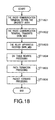
- radio communication terminal 107 When radio communication terminal 107 enters diversity area 110 (step 600) , the terminal 107 transmits to relay apparatus 101 DIVIN_MES including information indicating that the terminal 107 has entered diversity area 110, and further indicating base stations that cover diversity area 110 in which the terminal 107 is present, i.e. existing zone base station 108 and peripheral zone base station 109 (step 601).
- table rewrite section 105 recognizes that radio communication terminal 107 has moved out of diversity area 110 and is currently communicating with the base station 109.
- forwarding table 103 has a configuration where DC flag 406 is added to a basic table of MPLS, i.e., an extended configuration, and is the same as the general table of MPLS except DC flag 406, and therefore, it is possible to apply relay apparatus 101 to a general MPLS network.
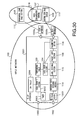
- relay apparatus 1501 positioned in the middle of MPLS network 100 performs control for forwarding packets to both of the two base stations, 108 and 109, corresponding to the position of radio communication terminal 107.
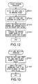
- a configuration of relay apparatus 1501 according to the second embodiment will be described below with reference to FIG. 16.
- the same sections as those already described are assigned the same reference numerals.
- DIV table 1604 is a table to store forward information on radio communication terminal 107 existing in diversity area 110.
- table rewrite section 1603 is capable of recognizing that radio communication terminal 107 is present in diversity area 110 and further recognizing the forward information on radio communication terminal 107.
- radio communication terminal 107 When radio communication terminal 107 enters diversity area 110 (ST1801), the terminal 107 transmits a message of location update to server 117 together with DIVIN_MES (ST1802).
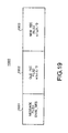
- DIVIN_MES 1900 includes information for recognizing the base station composing the diversity area that radio communication terminal 107 has entered.
- DIVIN_MES has two FEC fields
- DIVIN_MES has three or more FEC fields when a diversity area is composed of zones of three or more base stations, respectively.
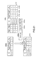
- relay apparatus 1501 has a DIV table as shown in 1604a and a table as shown in 103a, and in this sate, receives DIVIN_MES as shown in 1900a, in FIG.21.
- Path formation processing (ST1805) performed in relay apparatus 1501 will be described below specifically with reference to FIG.22.
- Receiving section 1602 in relay apparatus 1501 receives a label request message that is a message to inquire a value of the MPLS label which should be assigned to a packet when relay apparatus 1502 transmits the packet to radio communication terminal 107 via the base station 109, from relay apparatus 1502 on the server 117 side (ST2201).
- Message data fetching section 114 in relay apparatus 1501 fetches FEC (new FEC (FEC of peripheral zone base station 109)) included in the label request message, and provides the information that the arriving packet is a label request message and the value of new FEC to table rewrite section 1603 (ST2002).
- FEC new FEC (FEC of peripheral zone base station 109)
- Table rewrite section 1603 searches DIV table 1604 for an entry such that a value of FEC is the same as the value of new FEC, in order starting with the top (ST2209).
- table rewrite section 1603 performs setting such that the value of input port 401 indicates the port having received the label request message, the value of input label 402 is the value of the label in the label mapping message transmitted to relay apparatus 1502 in ST2103, and that DC flag 406 is "1" (ST2211).
- relay apparatus 1501 forwards the label request message to the output port corresponding to the new FEC (ST2214). Further, also when any entry is not detected with the same value of FEC as the value of new FEC in the DIV table in ST2209, table rewrite section shifts the processing to ST2214.
- relay apparatus 1501 sends a label mapping message back to relay apparatus 1502 (herein, it is assumed to send back "5" as the value of the label) (ST2203).
- Table rewrite section 1603 searches DIV table 1604b for an entry such that a value of FEC is the same as the value of new FEC, in order starting with the top, and detects entry 2102 that is a second one from the top (ST2209).
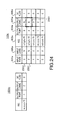
- table rewrite section 1603 makes entry 2304 on the new FEC ("e.f.g.h/0") as the top entry in forwarding table 103b (ST2110), and copies a value 2302 (in this example, "3") of output label, and a value 2303 (in this example, "5") of output port from DIV table 1604b to the new entry.
- the table is in a state as shown in 103b in FIG.23.
- table rewrite section 1603 deletes entry 2102 copied to forwarding table 103b from DIV table 1604b to set the DIV table for the state as shown in 1604c (ST2212).
- the table is in a state as shown in 103c.
- relay apparatus 1501 communicates a label request message and label mapping message with relay apparatus 1502 upstream from the apparatus 1501 and with relay apparatus 1503 downstream from the apparatus 1501, thereby acquires the label information, and rewrites forwarding table 103 so as to form the path to peripheral zone base station 109.
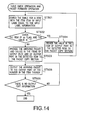
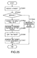
- the packet forward processing (ST1806) in relay apparatus 1501 will be described below with reference to FIG.25.
- message data fetching section 114 When the received packet is a message packet, message data fetching section 114 provides the type and content of the message to table rewrite section 1603.
- Table rewrite section 1603 performs the processing corresponding to the message, for example, the processing of ST1804 and ST1805 (ST2503).
- Label fetching section 115 extracts an MPLS label from the received packet (ST2504) to provide to table check section 104. Further, the section 115 outputs the received packet to packet copy section 106.
- Table check section 104 determines a packet forward destination from the MPLS label received from label fetching section 115, the input port number and forwarding table 103 (ST2505).
- relay apparatus 1501 When DIVOUT_MES is passed through relay apparatus 1501 of the present invention during a period of time DIVOUT_MES arrives at server 117 that is the communicating party from radio communication terminal 107, relay apparatus 1501 receives DIVOUT_MES (ST2603).
- Relay apparatus 1501 checks the content of DIVOUT_MES, and based on the content of DIVOUT_MES, performs processing for deleting the path to the base station 108 (ST2604). In addition, the path deletion processing in relay apparatus 1501 will be described later specifically.
- processing in ST2605 is the same as the processing in FIG.25 except the packet copy processing in ST2506, and therefore, specific descriptions thereof are omitted.
- the outline is as described above of the operation in relay apparatus 1501 when radio communication terminal moves out of diversity area 110.
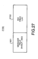
- relay apparatus 1501 receives from radio communication terminal 107.
- DIVOUT_MES is comprised of message field 1901 and FEC field 2702.
- DIVOUT_MES 2700 includes the information for identifying a base station with which radio communication terminal 107 is currently communicating.
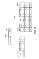
- message data fetching section 114 in relay apparatus 1501 fetches a value of FEC 2901, and table rewrite section 1603 searches forwarding table 103c in order starting with the top, and detects entry 2304 with the same value as in FEC 2901 of DIVOUT_MES 2900 (ST2801 and ST2802).
- Table rewrite section 1603 checks a value of DC flag 406a in entry 2304 (ST2803).
- Table write section 1603 searches forwarding table 103a continuously, and detects entry 2301 with the same value as in FEC 2901 of DIVOUT_MES 2900.
- the table is in a state as shown in 103d.
- relay apparatus 1501 when radio communication terminal 107 enters diversity area 110, relay apparatus 1501 stores the output port and output label information that is forward information corresponding to existing zone base station 108 in DIV table 1604, copies the information to forwarding table 103 in forming a path to peripheral zone base station 109 to associate with new FEC, input port and input label, and thereby is capable of forming paths not only to peripheral zone base station 109 corresponding to an area to which the terminal 107 moves, but also to existing zone base station 108 corresponding to an area with which communications have been carried out since an earlier time.
- Relay apparatus 3001 is provided with timer 3003.
- Timer 3003 measures a time having elapsed since reception of DIVIN_MES. When a predetermined time (expiration time) has elapsed since reception of DIVIN_MES, timer 3003 notifies table rewrite section 3002 of the lapse.
- the apparatus 3001 when a predetermined time has elapsed since relay apparatus 3001 received DIVIN_MES, irrespective of arrival of DIVOUT_MES, the apparatus 3001 is capable of deleting an entry on old FEC associated with received DIVIN_MES from forwarding table 103. As a result, when DIVOUT_MES does not arrive at relay apparatus 3001 from radio communication terminal 107 due to some reason, it is possible to prevent a situation where an unnecessary path is being formed continuously.
- the communication network control apparatus is capable of copying a packet to forward on the MPLS network, and when data transmission is carried out in a combination of the MPLS network and wireless communication networks, occurrences of packet loss are eliminated even when a radio communication terminal moves and performs handover.
Landscapes
- Engineering & Computer Science (AREA)
- Computer Networks & Wireless Communication (AREA)
- Signal Processing (AREA)
- Mobile Radio Communication Systems (AREA)
- Data Exchanges In Wide-Area Networks (AREA)
Abstract
Description
- The present invention relates to a communication network control apparatus and method that control communication networks when a radio communication terminal moves and performs handover.
- When a radio communication terminal moves from an area of a base station communicating with the terminal currently to an area of another base station starting communicating with the terminal, the terminal performs handover to switch base stations to communicate.
- However, when the radio communication terminal performs handover, there are cases that a data packet is transferred to the terminal before the connection is not switched between basestations.Thetransferred packet does not arrive at the radio communication terminal properly, and a packet loss occurs.
- Further, when the radio communication terminal moves fast, a time allowed to switch connections becomes short.
- Furthermore, in recent radio systems, the picocell has proceeds, and an area (cell) has become small which a single base station is capable covering.
- With the picocell thus proceeding, processing for switching connections occurs at a high rate, as a radio communication terminal moves. In such a situation, a packet loss tends to occur. Furthermore, coincidences of the picocell and fast moving of a radio communication terminal extremely degrade the communication quality in the radio communication terminal.
- Then, a method has been proposed for reserving a flow transmission band or preventing occurrences of loss of data packet when a radio communication terminal performs handover while moving.
- (For example, see Patent Document 1 (Japanese Laid-Open Patent Publication No.H11-313358), Non Patent Document 1 (Wen-Tsuen Chen, Li-Chi Huang, "RSVP Mobility Support: A Signaling Protocol for Integrated Services Internet with Mobile Hosts", IEEE INFOCOM 2000, pp. 1283-1292), Non-Patent Document 2 (Zhong Ren, Chen-Khong Tham, Chun-Choong Foo, Chi-Chung Ko, "Integration of Mobile IP and Multi-Protocol Label Switching", IEEE 2001, pp.2123-2127), and Non-Patent Document 3 (Heechang Kim, Kuok-Shoong D. Wong, Wai Chen and Chi Leung Lau, "Mobility-Aware MPLS in IP-based Wireless Access Networks", IEEE 2001, pp.3444-3448).) "A mobile communication network control apparatus" disclosed in
Patent Document 1 is of a method for preventing occurrences of loss of data packet. - Specifically, in the method, a multipath connection is set toward a radio communication base station communicating with a radio communication terminal and radio communication base stations around the radio communication terminal, and data packets are flooded on the set multipath connection. Thus, the packet loss is thus prevented by flooding data packets on the multipath connection.
- Non-Patent
Document 1 describes a method of reserving the flow transmission band. In the method, using RSVP (Resource Servation Protocol) that is a protocol to reserve a resource on a communication path, a transmission path is ensured to provide QoS assurance (reservation of flow transmission band). - Specifically, the method is to reserve transmission paths to base stations around a radio communication terminal before performing handover, using RSVP. QoS assurance is thus provided to the radio communication terminal also after performing the handover.
- Non-Patent
Documents - In the method, QoS assurance is provided using MPLS (Multi-Protocol Label Switching).
- The method disclosed in
Patent Document 1 intends to eliminate the packet loss due to handover, and does not consider anything about QoS assurance to radio communication terminals. Therefore, the method may not provide QoS assurance to radio communication terminals. - Non-Patent
Document 2 intends to provide QoS assurance to radio communication terminals even after performing handover, and does not consider the packet loss. - Further, in
Non-Patent Document 1, since a transmission path is reserved for a base station that does not communicate with a radio communication terminal actually, there arises a problem in terms of effective use of network. Specifically, when the number of radio communication terminals increases that connect to the network, a lot of bands remain unused and unused communication channels are left that can be used. Further, increases in useless communication channel result in a possibility that a packet loss occurs when a radio communication terminal moves fast. - Further, as in
Non-Patent Document 1, Non-PatentDocuments - Thus, the conventional methods have problems that it is not possible to provide QoS assurance to radio communication terminals while eliminating the packet loss due to handover.
- 5
- It is an object of the present invention to achieve QoS assurance to a radio communication terminal while eliminating the packet loss due to handover.
- In the present invention, a cable network upstream from base stations is constructed in MPLS, and when a radio communication terminal moves from an area of a base station currently communicating with the terminal to an adjacent area of another base station and enters a diversity areas of the two base stations, a communication network control apparatus provides paths (LSP: Label Switched Path) of MPLS to the two base stations, and copies a packet to the radio communication terminal to forward to both of the two base stations. Then, when the radio communication terminal moves out of the diversity area and enters the area of either of the base stations, the apparatus disconnects the path (LSP) to the base station whose area the terminal moves out of.
- It is thereby possible to assure QoS to the radio communication terminal and eliminate the packet loss in handover.
- The above and other objects and features of the invention will appear more fully hereinafter from a consideration of the following description taken in connection with the accompanying drawing wherein one example is illustrated by way of example.
- FIG.1 is a block diagram illustrating a configuration of communication networks and a relay apparatus in a first embodiment of the present invention;
- FIG.2 is a view showing a forwarding table in the first embodiment;
- FIG.3 is a view showing an example of a configuration of an MPLS header;
- FIG.4 is a flowchart to explain the table rewrite operation in a communication system when a radio communication terminal enters a diversity area according to the first embodiment;
- FIG.5 is a view showing an example of a configuration of DIVIN_MES;
- FIG.6 is a flowchart to explain the table rewrite operation in a table rewriting section when the radio communication terminal enters the diversity area according to the first embodiment;
- FIG.7 is a view showing a table in the first embodiment;
- FIG.8 is a flowchart to explain the table rewrite operation in the communication system when the radio communication terminal moves out of the diversity area according to the first embodiment;
- FIG. 9 is a view showing an example of a configuration of DIVOUT_MES;
- FIG.10 is a flowchart to explain the table rewrite operation in the table rewriting section when the radio communication terminal moves out of the diversity area according to the first embodiment;
- FIG.11 is another view showing a table in the first embodiment;
- FIG.12 is a flowchart to explain the packet forward operation in the relay apparatus in the first embodiment;
- FIG.13 is a flowchart to explain a label fetching section in the first embodiment;
- FIG.14 is a flowchart to explain the operations in a table check section and a packet copy section in the first embodiment;
- FIG. 15 is a schematic view of a communication system according to a second embodiment of the present invention;
- FIG.16 is a diagram illustrating a relay apparatus according the second embodiment;
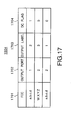
- FIG.17 is a configuration view of a DIV table according to the second embodiment;
- FIG.18 is a flow diagram of operation in the relay apparatus when a radio communication terminal enters a diversity area according to the second embodiment;
- FIG.19 is a configuration view of DIVIN_MES according to the second embodiment;
- FIG.20 is a flow diagram of DIV table rewrite processing in the relay apparatus according to the second embodiment;
- FIG.21 is a diagram to explain a specific example of the DIV table rewrite processing in the relay apparatus according to the second embodiment;
- FIG.22 is a flow diagram of path formation processing in the relay apparatus according to the second embodiment;
- FIG.23 is a first view to explain a specific example of the path formation processing in the relay apparatus according to the second embodiment;
- FIG.24 is a second view to explain the specific example of the path formation processing in the relay apparatus according to the second embodiment;
- FIG.25 is a flow diagram of packet forward processing in the relay apparatus according to the second embodiment;
- FIG.26 is a flow diagram of operation in the relay apparatus when the radio communication terminal moves out of the diversity area according to the second embodiment;
- FIG.27 is a configuration view of DIVOUT_MES according to the second embodiment;
- FIG. 28 is a flow diagram of path deletion processing in the relay apparatus according to the second embodiment;
- FIG.29 is a view to explain a specific example of the path deletion processing in the relay apparatus according to the second embodiment; and
- FIG.30 is a diagram illustrating a configuration of a relay apparatus according to a third embodiment of the present invention.
-
- The first embodiment of present invention will be described below. Referring to FIG.1, a communication system will be described first that includes a relay apparatus to which a communication network control apparatus according to the first embodiment is applied. FIG.1 is a diagram illustrating a configuration of the communication system provided with communication networks and the relay apparatus in the first embodiment of the present invention.
-
Communication system 10 is comprised ofserver 117,relay apparatus 101 onMPLS network 100, existingzone base station 109 and peripheralzone base station 109 that are connected via networks.Relay apparatus 101 applies the communication network control apparatus of the present invention. - In
communication system 10,radio communication terminal 107 is connected to existingzone base station 108 and peripheralzone base station 109 via radio communication networks.Radio communication terminal 107 continues communications while performing handover on the radio communication networks. The first embodiment assumes thatradio communication terminal 107 moves fromzone 111 that existingzone base station 108 covers to zone 112 that peripheralzone base station 109 covers while performing handover. - Existing
zone base station 108 is a base station with whichradio communication terminal 107 is currently communicating. Peripheralzone base station 109 is a base station that coverszone 112 adjacent to existingzone base station 108. - A region denoted by "110" in the figure indicates a diversity area where
zone 111 that existingzone base station 108 covers andzone 112 that peripheralzone base station 109 covers overlap each other. - A configuration of
relay apparatus 101 will be described below. - Receiving
section 113 receives a packet transmitted fromserver 117 to output to messagedata fetching section 114. - Message
data fetching section 114 checks whether the packet output from receivingsection 113 is a message packet, and when the packet is a message packet, provides the type and content of the message to tablerewrite section 105. When the packet output from receivingsection 113 is not a message packet, thesection 114 provides the packet to label fetchingsection 115. According to the type and content of the message received from messagedata fetching section 114,table rewrite section 105 rewrites forwarding table 103. The table rewrite operation intable rewrite section 105 will be described later specifically. -
Label fetching section 115 fetches information of MPLS label from the packet output frommessage fetching section 114 to provide totable check section 104. -
Table check section 104 checks forwarding table 103 based on a value of MPLS label received fromlabel fetching section 115 to determine a forward destination of the packet. - Forwarding table 103 stores forwarding information associated with the MPLS label. More specifically, forwarding table 103 is a table that indicates the relationship between a pair of an input port and label information of MPLS of an input packet and a pair of an output port that is a forwarding destination of the packet and label information of MPLS to assign in outputting.
- When the packet output from
label fetching section 115 is output to a plurality (the number of forward destinations) of output ports,packet copy section 106 makes the plurality of copies to output to transmittingsection 116. - Transmitting
section 116 receives packets frompacket copy section 106 to forward to forward destinations determined intable check section 104. - By thus constructing a cable network upstream from the
base stations MPLS network 100, it is possible to assure radio communication terminals of QoS. - When
radio communication terminal 107 intends to move fromzone 111 covered by existingzone base station 108 currently communicating withradio communication terminal 107 to zone 112 covered by adjacent peripheralzone base station 109 and entersdiversity area 110,relay apparatus 101 of the present invention provides paths (LSP) of MPLS to twobase stations radio communication terminal 107, and forwards the packet to both the twobase stations - However, the protocol in MPLS does not have the working to forward a packet to two LSPs. Therefore,
relay apparatus 101 of the present invention changes forwarding table 103 of MPLS from conventional one, and thus enables packets to be forwarded to both the twobase stations - Referring to FIG.2, forwarding table 103 will be described specifically that is one of features of the present invention. FIG.2 is a view showing an example of forwarding table 103.
- Forwarding table 103 stores items of
input port 401 indicative of a port number through which an arriving packet is input,input label 402 indicative of an MPLS label of the arriving packet,FEC 403 indicative of a destination address and class of the packet,output port 404 indicative of a number of a port to forward the arriving packet,output label 405 indicative of an MPLS label to assign in forwarding the arriving packet, andDC flag 406 indicative of whether there is another output destination forradio communication terminal 107 that is a transmission destination of the arriving packet with the items associated with one another. -
DC flag 406 takes a value of "1" or "0" whenradio communication terminal 107 is present indiversity area 110, while only taking a value of "0" when the terminal 107 is not present indiversity area 110. - In
output port 404, "1" indicates a port connected to peripheralzone base station 109, while "2" indicates a port connected to existingzone base station 108. - A configuration of an MPLS header will be described below with reference to FIG.3.
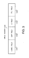
MPLS header 1200 is comprised of four fields,label field 1201,EXP field 1202,S field 1203 andTTL field 1204. -
Label field 1201 is a field to store a value of MPLS label. - EXP filed 1202 is a field reserved for experiment.
-
S field 1203 is a field to indicate whether the label is positioned at the end of a label stack when a plurality of labels overlaps in a label stack structure. The label is positioned at the end of the label stack when the value is "1", while being positioned at a portion except the end of the label stack. - TTL filed 1204 is a field in which is stored a value indicative of existing time of a packet.
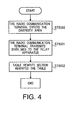
- Referring to FIG.4, the operation will be described below for rewriting forwarding table 103 in
relay apparatus 101 whenradio communication terminal 107 enters the diversity area. FIG.4 is a flowchart to explain the table rewrite operation inrelay apparatus 101 whenradio communication terminal 107 entersdiversity area 110. - When
radio communication terminal 107 enters diversity area 110 (step 600) , the terminal 107 transmits to relayapparatus 101 DIVIN_MES including information indicating that the terminal 107 has entereddiversity area 110, and further indicating base stations that coverdiversity area 110 in which the terminal 107 is present, i.e. existingzone base station 108 and peripheral zone base station 109 (step 601). - FIG.5 illustrates a configuration of DIVIN_MES.
DIVIN_MES 1300 is comprised of radio communicationterminal address field 1301, number-of-diversity area composingbase station field 1302, and diversity area composing base station address fields 1303. - Radio communication
terminal address field 1301 is a field to store an address of the radio communication terminal and a class to which the terminal belongs. - Number-of-diversity area composing
base station field 1302 is a field to store the number of base stations that compose the diversity area where the radio communication terminal exists. - Diversity area composing base station address fields 1303 are fields to store addresses of the base stations compose the diversity area.
- The number of diversity area composing base
station address fields 1300 corresponds to the number stored in number-of-diversity area composingbase station field 1302. In the example of FIG.5, since "2" is stored in number-of-diversity area composingbase station field 1302, there are two diversity area composing base station address fields, 1300a and 1300b. - Determination on whether a packet is
DIVIN_MES 1300 may be made by assigning a specific number to EXP filed 1202 in the MPLS header to determine or extending a new filed. In other words, it is only required to enableDIVIN_MES 1300 to be identified. - In the first embodiment, radio communication
terminal address field 1300 stores an address, "W.X.Y.Z", ofradio communication terminal 107. In this embodiment, since base stations composingdiversity area 110 are existingzone base station 108 and peripheralzone base station 109, "2" is stored in number-of-diversity area composingbase station field 1302. Diversity area composing base station address fields 1303 have a field in which is input an address, "e.f.g.h", of existingzone base station 108 and subsequent to the field, another field in which is input an address, "i.j.k.l", of peripheralzone base station 109. - In response thereto,
relay apparatus 101 receives DIVIN_MES intable rewrite section 105 and recognizes thatradio communication terminal 107 has entereddiversity area 110. Then,table rewrite section 105 rewrites forwarding table 103 based on the base station information in DIVIN_MES (step 602). - Thus, using DIVIN_MES transmitted from
radio communication terminal 107,table rewrite section 105 recognizes thatradio communication terminal 107 has entereddiversity area 110 and that thebase stations diversity area 110. - In addition, the first embodiment provides an aspect
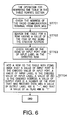
whereradio communication terminal 107 transmits DIVIN_MES, wherebytable rewrite section 105 recognizes that the terminal 107 has entereddiversity area 110, and another aspect may be provided. For example, a server may be provided which manages the position ofradio communication terminal 107 and transmits information indicating thatradio communication terminal 107 has entereddiversity area 110 to relayapparatus 101. - Referring to FIG.6, the operation will be described below specifically for rewriting forwarding table 103 in table rewrite section 105 (step 602). FIG.6 is a flowchart to explain the table rewrite operation in
table rewriting section 105 whenradio communication terminal 107 entersdiversity area 110. - First,
table rewrite section 105 checks the address ofradio communication terminal 107 and the class to which the radio communication terminal belongs to from DIVIN_MES (step 701). -
Table rewrite section 105 searches for a row having a value of the item ofFEC 403 being the address checked in step 701 (step 702). -
Table rewrite section 105 checks a value of the item ofinput port 401 and a value of the item ofinput label 402 in the row detected in step 702 (step 703). -
Table rewrite section 105 inserts a new row to the top in forwarding table 103. In each item of the inserted new row, a value ofinput port 401 is the value ofinput port 401 checked in step 703, a value ofinput label 402 is the value ofinput label 402 checked in step 703, a value ofFEC 403 is the address or class of the radio communication terminal checked in step 701, a value ofoutput port 404 is a number of the port that has received DIVIN_MES, a value ofoutput label 405 is "-", and a value ofDC flag 406 is "1" (step 704). - A specific example of table rewrite processing in
table rewrite section 105 will be described below with reference to FIGs.2 to 7. -
Table rewrite section 105 checks the address ofradio communication terminal 107 from the content of DIVIN_MES and obtains information of "W.X.Y.Z" (step 701). -
Table rewrite section 105 detects a second row such that a value of the item ofFEC 403 is "W.X.Y.Z" (step 702) from forwarding table as shown in FIG.7 (step 702). -
Table rewrite section 105 checks a value of "1" in the item ofinput port 401 and a value of "2" in the item of input label 402 (step 703) in the second row in the table as shown in FIG.7 (step 703). - Finally,
table rewrite section 105 adds a row such that a value of the item ofinput port 401 is "1", a value of the item ofinput label 402 is "2", a value ofFEC 403 is "W.X.Y.Z", a value of the item ofoutput label 405 is "-", and that a value of the item ofDC flag 406 is "1" to the top of forwarding table 103 as shown in FIG.7, and generates forwarding table 103 as shown in FIG.2 (step 704). - Thus, when
radio communication terminal 107 entersdiversity area 110, forwarding table 103 is rewritten, and it is thereby possible to set a plurality of pairs of output ports and output labels with respect to a single pair of an input port and input label, and to expand paths of MPLS to a plurality of base stations (herein, two base stations, 108 and 109). As a result, the relay apparatus is capable of forwarding packets to all of the plurality of base stations (herein, two base stations, 108 and 109), and of preventing the packet loss. - The operation will be described below when
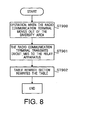
radio communication terminal 107 moves out of the diversity area with reference to FIG.8. FIG.8 is a flowchart to explain the table rewrite operation inrelay apparatus 101 whenradio communication terminal 107 moves out ofdiversity area 110. - When
radio communication terminal 107 moves out of diversity area 110 (step 900), the terminal 107 transmits to relayapparatus 101 DIVOUT_MES including information indicating that the terminal 107 has moved out ofdiversity area 110, and further indicating a base station with which the terminal is currently communicating, i.e. peripheral zone base station 109 (step 901). - In response thereto,
table rewrite section 105 recognizes thatradio communication terminal 107 has moved out ofdiversity area 110 from the content of DIVOUT_MES. Then,table rewrite section 105 rewrites forwarding table 103 based on the base station information in DIVOUT_MES (step 902). - Thus, by receiving DIVOUT_MES transmitted from
radio communication terminal 107,table rewrite section 105 recognizes thatradio communication terminal 107 has moved out ofdiversity area 110 and is currently communicating with thebase station 109. - FIG.9 illustrates a configuration of DIVOUT_MES.
DIVOUT_MES 1400 is comprised of radio communicationterminal address field 1401 and communicating basestation address field 1402. - Radio communication
terminal address field 1401 is a field to store an address of the radio communication terminal and a class to which the terminal belongs. - Communicating base
station address field 1402 is a filed to store an address of a base station with whichradio communication terminal 107 is currently communicating. - Determination on whether a packet is
DIVOUT_MES 1400 may be made by assigning a specific number to EXP filed 1202 in the MPLS header to determine or extending a new filed. In other words, it is only required to enableDIVOUT_MES 1400 to be identified. - In the first embodiment, radio communication
terminal address field 1401 stores the address, "W.X.Y.Z", ofradio communication terminal 107. In this embodiment, since the base station with whichradio communication terminal 107 is currently communicating is peripheralzone base station 109, thefield 1401 is followed by a field having the address, "i.j.k.l", of the peripheralzone base station 109. - In addition, the first embodiment provides an aspect where
radio communication terminal 107 transmits DIVOUT_MES, wherebytable rewrite section 105 recognizes that the terminal 107 has moved out ofdiversity area 110, and another aspect may be provided. For example, a server may be provided which manages the position ofradio communication terminal 107 and transmits information indicating thatradio communication terminal 107 has moved out ofdiversity area 110 to relayapparatus 101. - Referring to FIG.10, the operation (step 902) will be described below specifically for rewriting forwarding table 103 in
table rewrite section 105. - First,
table rewrite section 105 checks the address ofradio communication terminal 107 from DIVOUT_MES transmitted from the terminal 107 (step 1001). -
Table rewrite section 105 searches forwarding table 103 for a row having a value of the item ofFEC 403 being the address checked in step 1001 (step 1002). -
Table rewrite section 105 checks a value of the item ofoutput port 404 in the row detected in step 1002 (step 1003). -
Table rewrite section 105 checks whether a value of the item ofoutput 404 in the row detected in step 1002 indicates the port that has received DIVOUT_MES (step 1004). - When the value of the item of
output port 404 in the row detected in step 1002 is the same as the value of the port having received DIVOUT_MES, the row detected in step 1002 is a row to forward to a port connected with the base station currently communicating withradio communication terminal 107, and needs to be left. Therefore, in this case,table rewrite section 105 checks the item ofDC flag 406 in the row detected in step 1002, and whenDC flag 406 is "1", changes to "0" (step 1005). - Meanwhile, when the value of the item of
output port 404 in the row detected in step 1002 is different from the number of the port having received DIVOUT_MES, the row detected in step 1002 is a row to forward to a base station different from the base station currently communicating withradio communication terminal 107. Therefore,table rewrite section 105 deletes the row detected in step 1002 (step 1006). - Then,
table rewrite section 105 continues the operations of steps 1003 and 1004, and of step 1005 or 1006 until the last row of forwarding table 103 (step 1007). - A specific example of the table rewrite processing in
table rewrite section 105 will be described below with reference to FIGs.2, 8 and 10. -
Table rewrite section 105 checks the address ofradio communication terminal 107 from DIVOUT_MES transmitted fromradio communication terminal 107 and obtains information of "W.X.Y.Z" (step 1001). -
Table rewrite section 105 detects a first row in forwarding table 103 as shown in FIG.2, as a row such that a value of the item ofFEC 403 is "W.X.Y.Z", from forwarding table 103 (step 1002). -
Table rewrite section 105 checks the value of "1" in the item ofoutput port 404 in the first row in forwarding table 103 as shown in FIG.2 (step 1003). - In this case, the port having received DIVOUT_MES is "1", and so, the value indicates the same port as the output port having received DIVOUT_MES (step 1004). Therefore,
table rewrite section 105 checks the item ofDC flag 406, changes the value to "0", and leaves the row (step 1005). - Next,
table rewrite section 105 detects a third row with the value of the item ofFEC 403 being "W.X.Y.Z" as shown in FIG. 2 from remaining rows in forwarding table 103 (step 1002). -
Table rewrite section 105 checks the value of "2" in the item ofoutput port 404 in the third row in forwarding table 103 as shown in FIG.2 (step 1003). The port having received DIVOUT_MES is "1", which is different from the value in the item of theoutput port 404 in the third row in forwarding table 103 as shown in Table 2, and therefore,table rewrite section 105 deletes the third row and obtains forwarding table 103 as shown in FIG.11 (step 1006). - Thus, by rewriting forwarding table 103, when
radio communication terminal 107 moves out of the diversity area and enters the zone ofbase station 109,relay apparatus 101 deletes a pair of the output port and output label corresponding to thebase station 108 from which the terminal 107 moves, and thereby disconnects the path (LSP) tobase station 108 from which the terminal 107 moves. As a result, it is possible to prevent increases in number in useless communication channel, and to prevent wasteful use in communication networks. - The packet forward operation will be described below when
relay apparatus 101 receives packets except the message packet. FIG.12 is a flowchart to explain the packet forward operation inrelay apparatus 101. - In
relay apparatus 101, receivingsection 113 receives a packet toradio communication terminal 107, messagedata fetching section 114 checks whether the received packet is a message packet (herein, the packet is not a message packet), andlabel fetching section 115 detects an MPLS label of the received packet (step 201). - In
relay apparatus 101,table check section 104 checks forwarding table 103 and determines an output port (step 202). -
Table check section 104 outputs the output port number and output label determined in step 202 topacket copy section 106, and outputs the output port number to transmitting section 116 (step 203). -
Packet copy section 106 makes a number of copies of the packet corresponding to the number of output ports, and replaces the MPS label with the output label acquired fromtable check section 104 to output to transmittingsection 116. Then, based on the received output port numbers, thesection 116 forwards arriving packets frompacket copy section 106 to forward to thebase stations 108 and 109 (step 204). - The packet forward operation in
relay apparatus 101 will be described below with reference to FIGs.13 and 14. The label detecting operation inlabel fetching section 115 will be described first with reference to FIG.13. FIG.13 is a view to explain the operation (step 201) inlabel fetching section 115. -
Label fetching section 115 reads the MPLS label of the arriving packet from the label field in the MPLS header of the arriving packet (step 301). -
Label fetching section 115 outputs the MPLS label information that is a result detected in step 301 to table check section 104 (step 302). - In the example of the first embodiment,
label fetching section 115 reads the value of "2" as the MPLS label from the MPLS header of the arriving packet. Then, thesection 115 outputs the MPLS label information (the value of "2") which is the detection result totable check section 104, and further outputs the arriving packet topacket copy section 106. - The table check operation (steps 202 and 203) in
table check section 104 and the packet forward operation (step 204) inpacket copy section 106 and transmittingsection 116 will be described below with reference to FIG.14. FIG.14 is a flowchart to explain the operations inpacket check section 104,packet copy section 106 and transmittingsection 116. -
Table check section 104 searches forwarding table 103 for a row such that the item ofinput label 402 is equal to the MPLS label obtained fromlabel fetching section 115, and that the item of input port is equal to the number of the port having received the packet (step 501) . - When
table check section 104 detects from forwarding table 103 the row such that the item of input label is equal to the MPLS label obtained fromlabel fetching section 115, and that the item of input port is equal to the number of the port having received the packet, thesection 104 checks the item ofDC flag 406 in the detected row (step 502). - When a value in the item of
DC flag 406 checked in step 502 is "0",radio communication terminal 107 is not present indiversity area 110. Accordingly, in this case,table check section 104 provides topacket copy section 106 the value in the item ofoutput port 404 in the row detected in step 501 and the value ofoutput label 405 in this row (step 503). - Meanwhile, when a value in the item of
DC flag 406 checked in step 502 is "1",radio communication terminal 107 is present indiversity area 110. In this case, the received arriving packet should be copied and forwarded to peripheralzone base station 109 too. Accordingly, in this case,table check section 104 provides topacket copy section 106 the value in the item ofoutput port 404 in the row detected in step 501 and the value ofoutput label 405 in this row, and shifts to the processing in step 501 for searching for information for forwarding to another base station (step 504). - Then, in order to obtain the output port connected with peripheral
zone base station 109,table check section 104 searches remaining rows in forwarding table 103 for a row such that the item of input label is equal to the MPLS label obtained fromlabel fetching section 115, and that the item of input port is equal to the number of the port having received the packet (step 501). Whentable check section 104 detects from the remaining rows in forwarding table 103 the row such that the item ofinput label 402 is equal to the MPLS label obtained fromlabel fetching section 115, and that the item of input port is equal to the number of the port having received the packet, thesection 104 checks the item ofDC flag 406 in the detected row (step 502). - When a value in the item of
DC flag 406 checked in step 502 is "1", there exists another peripheral zone base station that composesdiversity area 110 whereradio communication terminal 107 is present. Accordingly, in this case,table check section 104 provides topacket copy section 106 the value of the item ofoutput port 404 in the row detected in step 501 and the value ofoutput label 405 in this row (step 504). Then, in order to obtain the output port connected with the another peripheral zone base station composingdiversity area 110 whereradio communication terminal 107 is present,table check section 104 further searches the remaining rows in forwarding table 103 for a row such that the item of input label is equal to the MPLS label obtained fromlabel fetching section 115, and that the item of input port is equal to the number of the port having received the packet (step 501). -
Table check section 104 repeats the operations of steps 501, 502 and 504, until the item ofDC flag 406 is "0" in the detected row. - When the item of
DC flag 406 is "0", there is no other base station that composesdiversity area 110 whereradio communication terminal 107 is present. Accordingly, in this case,table check section 104 provides topacket copy section 106 the value of the item ofoutput port 404 in the detected row and the value of the item ofoutput label 405 in the detected row (step 503) . - In response thereto,
packet copy section 106 makes copies of the arriving packet output fromlabel fetching section 115, where the number of the copies corresponds to the number of output ports provided fromtable check section 104minus 1. Thesection 106 replaces the MPLS label of the packet using the value of output label provided fromtable check section 104, and outputs the packet to transmittingsection 116 together with the information of output port provided fromtable check section 104. Transmittingsection 116 forwards the packet received frompacket copy section 106 to an output port with the output port number received from packet copy section 106 (step 505). - Then,
packet copy section 106 and transmittingsection 116 repeat the operation of step 505 the number of times the same as the number of pieces of output information obtained from table check section 104 (step 506). - In the example in the first embodiment,
table check section 104 checks items ofinput label 402 in ascending order in forwarding table 103, and detects a first row
where the input label is equal to MPLS label information "2" obtained fromlabel fetching section 115, and the input port is equal to the number of the port (herein, assumed as "4") through which the packet is input (step 501). - Next,
table check section 104 checks the item ofDC flag 406 in the first row in forwarding table 103 as shown in Table 2 (step 502). In the first embodiment, since the item ofDC flag 406 in the first row has "1",radio communication terminal 107 is present indiversity area 110. Accordingly,table check section 104 provides topacket copy section 106 the value of "1" in the item ofoutput port 404 and the value of "-" in the item ofoutput label 405 in the first row in forwarding table 103 as shown in FIG.2 (step 504). -
Table check section 104 searches forwarding table 103 as shown in FIG.2 for a row such that a value ofinput port 401 is "4" and a value in the item ofinput label 402 is "2", in ascending order starting with the second row (step 501). Then, thesection 104 detects a third row where the value of the item ofinput port 401 is "4" and the value of the item ofinput label 402 is "2" in forwarding table 103 as shown in FIG.2. - Since the value of the item of DC flag is "0" in the third row in forwarding table 103 as shown in FIG.2, table check section determines that there is no other base station that composes
diversity area 110, and provides topacket copy section 106 the value of "2" in the item ofoutput port 404 and the value of "-" in the item ofoutput label 405 in the third row in forwarding table 103 as shown in FIG.2 (503). - In response thereto, based on the output port information "1" and output label information "-" ("-" means removing the MPLS header) obtained from
table check section 104,packet copy section 106 forwards data of the arriving packet output fromlabel fetching section 115 to the output port ofnumber 1 connected with existing zone base station 108 (step 505). - Further, since
packet copy section 106 receives another output port information, "2", (step 504), thesection 106 forwards the arriving packet to the output port ofnumber 2 connected with peripheralzone base station 109, based on the output port information "2" and output label information "-" (step 505). - As described above, according to the first embodiment, it is possible to set a
single input label 402 for a plurality ofoutput ports 404 in forwarding table 103. It is therebypossible to construct multi-path in the system where a portion upstream from thebase stations MPLS network 100. As a result, it is possible not only to provide QoS assurance toradio communication terminal 107 using MPLS, but also to eliminate the packet loss due to handover. - Further, according to the first embodiment, when
radio communication terminal 107 entersdiversity area 101, forwarding table 103 associates a pair ofinput port 401 and input label (MPLS label) 402 of the received packet withoutput ports 404 that are forward information of a plurality of base stations, 108 and 109, composingdiversity area 110. In this way, whenradio communication terminal 107 entersdiversity area 110 and performs handover, it is possible to expand paths to the plurality of base stations, 108 and 109. Moreover, the path is expanded when radiobase station terminal 107 performs handover, and then disconnected when the terminal moves out of the diversity area, thus enabling the effective use of communication network. Accordingly, it is possible to provide QoS assurance toradio communication terminal 107 while using the communication network efficiently, and further to prevent the packet loss in handover. - Furthermore, according to the first embodiment, when
radio communication terminal 107 moves out ofdiversity area 110, it is possible to associate in forwarding table 103 a pair ofinput port 401 and input label (MPLS label) 402 of the received packet only with the forward information of thebase station 109 communicating withradio communication terminal 107. As a result, it is possible to expand the path only to thebase station 109 with whichradio communication terminal 107 is currently communicating to enable packets to be forwarded. Accordingly, the need is eliminated of expanding an unnecessary path, and it is thereby possible to prevent the packet loss while using the communication network efficiently. - Moreover, in the first embodiment, forwarding table 103 has a configuration where
DC flag 406 is added to a basic table of MPLS, i.e., an extended configuration, and is the same as the general table of MPLS exceptDC flag 406, and therefore, it is possible to applyrelay apparatus 101 to a general MPLS network. - The outline of a communication system according to the second embodiment of the present invention will be describedwith reference to FIG.15. In addition, the same sections as those already described are assigned the same reference numerals.
- In the first embodiment,
relay apparatus 101, positioned at the end portion on theradio communication terminal 107 side onMPLS network 100, forwards packets to both two base stations, 108 and 109. In contrast thereto, incommunication system 1500 according to the second embodiment, a relay apparatus positioned in the middle ofMPLS network 100 performs control for forwarding packets to both of the two base stations, 108 and 109. It is assumed that "1501" denotes the relay apparatus of the present invention, and that "1502" and "1503" denote relay apparatuses with generation MPLS functions. - When
radio communication terminal 107 entersdiversity area 110, the terminal 107 transmits DIVIN_MES toserver 117. - When DIVIN_MES is passed through the relay apparatus of the present invention inside
MPLS network 100 while being forwarded fromradio communication terminal 107 toserver 117, the relay apparatus of the present invention receives DIVIN_MES to store. In the section embodiment,relay apparatus 1503a inMPLS network 100 receives DIVIN_MES to transmit to relayapparatus 1500 positioned in the middle ofMPLS 100. Then,relay apparatus 1500 that is the relay apparatus of the present invention receives and stores DIVIN_MES. - Since
radio communication terminal 107 enters the diversity area, LSP is formed fromserver 117 toradio communication terminal 107 viabase station 108. At this point, when two LSPs are extended,relay apparatus 1501 rewrites the table so that forward destinations of packets respectively correspond to the two LSPs, and floods packets transmitted fromserver 117 viarelay apparatus 1502, i.e., forwards the packets, to both the twobase stations diversity area 110 until DIVOUT_MES arrives at therelay apparatus 1501. -
Radio communication terminal 107 transmits DIVOUT_MES in moving out ofdiversity area 110, and whenrelay apparatus 1501 receives DIVOUT_MES, flooding is finished. - As described above,
relay apparatus 1501 positioned in the middle ofMPLS network 100 performs control for forwarding packets to both of the two base stations, 108 and 109, corresponding to the position ofradio communication terminal 107. A configuration ofrelay apparatus 1501 according to the second embodiment will be described below with reference to FIG. 16. In addition, the same sections as those already described are assigned the same reference numerals. -
Relay apparatus 1501 is provided withreceiving section 1602. Receivingsection 1602 receives a packet to output to messagedata fetching section 114. In addition, the number ofrelay apparatuses 1502 may be one or more. Further, receivingsection 1602 may receive a packet directly fromserver 117. - According to the type and content of a message received from message
data fetching section 114, table rewrite section 1063 rewrites DIV table 1604 and forwarding table 103. - DIV table 1604 is a table to store forward information on
radio communication terminal 107 existing indiversity area 110. By referring to DIV table 1604,table rewrite section 1603 is capable of recognizing thatradio communication terminal 107 is present indiversity area 110 and further recognizing the forward information onradio communication terminal 107. - A configuration of DIV table 1604 will be described below with reference to FIG.17.
- DIV table 1604 stores items of
FEC 1701 indicative of a destination address and class of the packet,output port 1702 indicative of a number of a port to forward the arriving packet,output label 1703 indicative of an MPLS label set in forwarding the arriving packet, andDC flag 1704 indicative of whether there is another output destination forradio communication terminal 107 that is a transmission destination of the arriving packet with the items associated with one another. -
DC flag 1704 takes a value of "1" or "0" whenradio communication terminal 107 is present indiversity area 110, while only taking a value of "0" when the terminal 107 is not present indiversity area 110. - In
output port 1702, "1" indicates a port connected to peripheralzone base station 109, while "2" indicates a port connected to existingzone base station 108. -
Relay apparatus 1501 according to the second embodiment is thus configured. - The operation in
relay apparatus 1501 will be described below specifically. - First, the operation in
relay apparatus 1501 whenradio communication terminal 107 entersdiversity area 110 will be described with reference to FIG.18. - When
radio communication terminal 107 enters diversity area 110 (ST1801), the terminal 107 transmits a message of location update toserver 117 together with DIVIN_MES (ST1802). - When DIVIN_MES is passed through
relay apparatus 1501 while being provided fromradio communication apparatus 107 toserver 117 that is a communicating party,relay apparatus 1501 receives DIVIN_MES in receiving section 1602 (ST1803). Then, according to the content of DIVIN_MES,relay apparatus 1501 rewrites DIV table 1604 (ST1804). In addition, the processing for rewriting DIV table 1604 will be described specifically later. - When the path is formed to
base station 109 viarelay apparatus 1501, theapparatus 1501 performs processing for forming the path (ST1805). In addition, the processing will be described later specifically for forming the path inrelay apparatus 1501. - Then, when
relay apparatus 1501 receives a packet toradio communication terminal 107, theapparatus 1501 forwards the packet toradio communication terminal 107 using forwarding table 103 (ST1806). In addition, the packet forward processing in ST1806 will be described specifically later. - The outline of the operation in
relay apparatus 1501 is described above whenradio communication terminal 107 entersdiversity area 110. - Referring to FIG.19, DIVIN_MES will be described below that
relay apparatus 1501 receives fromradio communication apparatus 107. -
DIVIN_MES 1900 is comprised ofmessage field 1901,old FEC field 1902, andnew FEC field 1903. -
Message field 1901 is a field to describe the type of a message. The message field is to determine whether a packet is of message, and when the packet is of message, further determine the type of the message. In addition, determination on a packet may be made by assigning a specific number to EXP filed 1202 in the MPLS header, instead of providingmessage field 1901. In other words, it is only required to enableDIVIN_MES 1900 to be identified. -
Old FEC field 1902 is a field to store an address of abase station with which a radio communication terminal having enteringdiversity area 110 has communicated previously. -
New FEC field 1903 is a field to store an address of a base station composing a field thatradio communication terminal 107 having entereddiversity area 110 enters this time. - As described above,
DIVIN_MES 1900 includes information for recognizing the base station composing the diversity area thatradio communication terminal 107 has entered. In addition, while in the example in FIG.19, DIVIN_MES has two FEC fields, DIVIN_MES has three or more FEC fields when a diversity area is composed of zones of three or more base stations, respectively. - DIV table rewrite processing (ST1804) in
relay apparatus 1501 will be described with reference to FIG.20. - Message
data fetching section 114 inrelay apparatus 1501 fetches fromDIVIN_MES 1900 a value of current FEC 1902 (on the base station A side) and a value of new FEC 1903 (on the base station B side) (ST2000). Then,message fetching section 114 provides information indicating that the arriving packet is DIVIN_MES,new FEC 1903 andcurrent FEC 1902 to table rewrite section 1603 (ST2001). -
Table rewrite section 1603 searches forwarding table 103 in order starting with the top for an entry such that a value ofFEC 403 is the same as the value of current FEC(A) 1902 (ST2002). - When detecting the entry such that the value of
FEC 403 is the same as the value of current FEC (A) 1902,table rewrite section 1603 newly makes an entry on new FEC(B) 1903 in DIV table 1604, and copies values ofoutput label 404,output port 405 andDC flag 406 of the entry with the same value as that of current FEC(A) 1902 detected from forwarding table 103 tooutput label 1702,output port 1703 andDC flag 1704 in DIV table 1604, respectively (ST2003). - Next,
table rewrite section 1603 determines whether the copied value ofDC flag 1704 is "1" or "0" (ST2004) , and whenDC flag 1704 is "0", forwards received DIVIN_MES to a next relay apparatus to finish the processing since an entry with current FEC (A) 1902 is not present any more in forwarding table 103 (ST2005). - Meanwhile, when
DC flag 1704 is "1" in ST2004, since an entry with current FEC (A) 1902 is present in forwarding table 103, thesection 1603 performs the processing of ST2002 to ST2004 until an entry with current FEC (A) 1902 is not present, i.e.,DC flag 1704 is "0". - Thus, the information on
current FEC 1902 stored in the table 103 is stored in DIV table 1604. - Further, when in ST2002, any entry with the same value of
FEC 403 as that of current FEC(A) 1902 is not detected among entries stored in forwarding table 103, thesection 1603 forwards received DIVIN_MES to a next relay apparatus, and finishes the processing (ST2005). - A specific example of the processing for rewriting DIV table 1604 in
relay apparatus 1501 will be described below with reference to FIG.21. - It is assumed that
relay apparatus 1501 has a DIV table as shown in 1604a and a table as shown in 103a, and in this sate, receives DIVIN_MES as shown in 1900a, in FIG.21. - In this case, message
data fetching section 114 inrelay apparatus 1501 fetches a value (a.b.c.d/0) ofold FEC 1902a and a value (e.f.g.h/0) ofnew FEC 1903a fromDIVIN_MES 1900a (ST2001). - Message
data fetching section 114 provides information indicating that the arriving packet is DIVIN_MES, the value (e.f.g.h/0) ofnew FEC 1903a, and value (a.b.c.d/0) ofold FEC 1902a totable rewrite section 1603. -
Table rewrite section 1603 detectsentry 2101 with the same value as the value (a.b.c.d/0) ofold FEC 1902a in forwarding table 103a (ST2002). -
Table rewrite section 1603 newly makes an entry onnew FEC 1903a in DIV table 1604a, and copies values ofoutput label 2104,output port 2103 andDC flag 2105 ofentry 2101 with the same value as that ofold FEC 1902a detected from forwarding table 103a to entry 2102 (ST2003). As a result, the DIV table is as shown in 1604b. - As described above,
relay apparatus 1501 performs the processing for rewriting DIV table 1604, and thereby is capable of leaving in DIV table 1604 the forward information, i.e., the output label and output port, to communicate with thebase station 108 in the existing zone whereradio communication terminal 107 has existed since an earlier time. - Path formation processing (ST1805) performed in
relay apparatus 1501 will be described below specifically with reference to FIG.22. - Receiving
section 1602 inrelay apparatus 1501 receives a label request message that is a message to inquire a value of the MPLS label which should be assigned to a packet whenrelay apparatus 1502 transmits the packet toradio communication terminal 107 via thebase station 109, fromrelay apparatus 1502 on theserver 117 side (ST2201). - Message
data fetching section 114 inrelay apparatus 1501 fetches FEC (new FEC (FEC of peripheral zone base station 109)) included in the label request message, and provides the information that the arriving packet is a label request message and the value of new FEC to table rewrite section 1603 (ST2002). - According to a label distribution protocol,
relay apparatus 1501 sends a label mapping message given a label of new FEC back to relay apparatus 1502 (ST2203). -
Table rewrite section 1603 makes an entry such thatinput port 401 is set at the port that has received the label request message,input label 402 is set at the value of the label sent back in the label mapping message,output port 404 is set at an output port to output a packet to new FEC, FEC is set at new FEC, and that the DC flag is set at "0" (ST2204 to ST2208). -
Table rewrite section 1603 searches DIV table 1604 for an entry such that a value of FEC is the same as the value of new FEC, in order starting with the top (ST2209). - When detecting the entry with the same value of FEC as the value of new FEC in DIV table 1604,
table rewrite section 1603 makes an entry on the new FEC as the top entry in forwarding table 103 (ST2110), and copies values ofoutput label 1702 andoutput port 1703 from DIV table 1604. - Then,
table rewrite section 1603 performs setting such that the value ofinput port 401 indicates the port having received the label request message, the value ofinput label 402 is the value of the label in the label mapping message transmitted to relayapparatus 1502 in ST2103, and thatDC flag 406 is "1" (ST2211). - By thus copying the output port and output label information corresponding to the path used earlier stored in DIV table 1604 to forwarding table 103,
relay apparatus 1501 forms the path to existingzone base station 108. - Next,
table rewrite section 1603 deletes the entry copied to forwarding table 103 from DIV table 1604 (ST2212). - When the value of DC flag in the deleted entry in DIV table 1604 is "1" (ST2213), since there is another entry on new FEC, the processing flow returns to ST2209, and
table rewrite section 1603 performs the same processing on an entry left in DIV table 1604 and performs the processing of ST2209 to ST2213 until any entry on new FEC is not present (the value of DC flag in the deleted entry is "0"). - Meanwhile, when the value of DC flag in the deleted entry in DIV table 1604 is "0",
relay apparatus 1501 forwards the label request message to the output port corresponding to the new FEC (ST2214). Further, also when any entry is not detected with the same value of FEC as the value of new FEC in the DIV table in ST2209, table rewrite section shifts the processing to ST2214. - In
relay apparatus 1501, receivingsection 1602 receives the label mapping message transmitted fromrelay apparatus 1503a (ST2215), andmessage fetching section 114 fetches a value of the label in label mapping message to output totable rewrite section 1603. -
Table rewrite section 1603 inputs the value of the label in the label mapping message tooutput label field 405 in the entry in forwarding table 103 made in receiving the label request message being processed (ST2216). - A specific example of the path formation processing (ST1805) in
relay apparatus 1501 will be described below with reference to FIGs.22 to 24. - When receiving
section 1602 receives a label request message including FEC "e.f.g.h" (ST2201), messagedata fetching section 114 fetches FEC "e.f.g.h" contained in the label request message, and provides the information that the arriving packet is a label request message and FEC "e.f.g.h" to table rewrite section 1603 (ST2002). - According to a label distribution protocol,
relay apparatus 1501 sends a label mapping message back to relay apparatus 1502 (herein, it is assumed to send back "5" as the value of the label) (ST2203). -
Table rewrite section 1603 makes an entry such thatinput port 401 is set at the port having received the label request message (in this example, "2"),input label 402 is set at the value of the label sent back in the label mapping message (in this example, "5"),output port 404 is set at an output port to output a packet to new FEC (in this example, "1"), FEC is set at new FEC (in this example, "e.f.g.h"), and thatDC flag 406 is set at "0" (ST2204 to ST2208). -
Table rewrite section 1603 searches DIV table 1604b for an entry such that a value of FEC is the same as the value of new FEC, in order starting with the top, and detectsentry 2102 that is a second one from the top (ST2209). - Then,
table rewrite section 1603 makes entry 2304 on the new FEC ("e.f.g.h/0") as the top entry in forwarding table 103b (ST2110), and copies a value 2302 (in this example, "3") of output label, and a value 2303 (in this example, "5") of output port from DIV table 1604b to the new entry. -
Table rewrite section 1603 setsentry 2302 in forwarding table 103a for values such that the value ofinput port 401 is the number (in this example, "2") of the port having received the label request message, the value ofinput label 402 is the value (in this example, "5") of the label in the label mapping message sent back in ST2203, and thatDC flag 406 is "1" (ST2211). - Thus, the table is in a state as shown in 103b in FIG.23.
- Next,
table rewrite section 1603 deletesentry 2102 copied to forwarding table 103b from DIV table 1604b to set the DIV table for the state as shown in 1604c (ST2212). -
Relay apparatus 1501 forwards the label request message to the output port (in this example, "4") corresponding to FEC (e.f.g.h) (ST2214). Then, inrelay apparatus 1501, receivingsection 1602 receives the label mapping message transmitted fromrelay apparatus 1503a (ST2215) , andtable rewrite section 1603 inputs the value (in this example, "8") oflabel 2401 in the label mapping message tooutput label field 405a in the entry in forwarding table 103b made in receiving the label request message. - As a result, the table is in a state as shown in 103c.
- As described above,
relay apparatus 1501 communicates a label request message and label mapping message withrelay apparatus 1502 upstream from theapparatus 1501 and with relay apparatus 1503 downstream from theapparatus 1501, thereby acquires the label information, and rewrites forwarding table 103 so as to form the path to peripheralzone base station 109. - The packet forward processing (ST1806) in
relay apparatus 1501 will be described below with reference to FIG.25. - Receiving
section 1602 receives a packet (ST2501), and outputs the received packet tomessage fetching section 114. - Message
data fetching section 114 checks whether the receivedpacket is of message to perform any processing, i.e., DIVIN_MES, DIVOUT_MES, label request message or label mapping message (ST2502). - When the received packet is a message packet, message
data fetching section 114 provides the type and content of the message to tablerewrite section 1603.Table rewrite section 1603 performs the processing corresponding to the message, for example, the processing of ST1804 and ST1805 (ST2503). - Meanwhile, when the received packet is a packet other than the message packet, message
data fetching section 114 outputs the received packet to label fetchingsection 115. -
Label fetching section 115 extracts an MPLS label from the received packet (ST2504) to provide totable check section 104. Further, thesection 115 outputs the received packet topacket copy section 106. -
Table check section 104 determines a packet forward destination from the MPLS label received fromlabel fetching section 115, the input port number and forwarding table 103 (ST2505). - When there is a plurality of forward destinations,
table check section 104 outputs a packet copy instruction topacket copy section 106. - According to the instruction from
table check section 115,packet copy section 106 copies the packet when necessary (ST2506).Packet copy section 106 outputs the received copy and (if copied) copied packets to transmittingsection 116. - According to an instruction from
table check section 104, transmittingsection 116 outputs the packet to an appropriate output port (ST2507). - As described above,
relay apparatus 1501 forwards a received packet to a predetermined destination according to forwarding table 103. Accordingly, when a plurality of destinations of a received packet is recorded in forwarding table 103, the received packet is forwarded to a plurality of destinations. - Referring to FIG. 26, the operation will be described below in
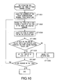
relay apparatus 1501 whenradio communication terminal 107 moves out of diversity area 110 (or completes handover). - When
radio communication terminal 107 moves out of diversity area 110 (ST2601), the terminal 107 transmits DIVOUT_MES to server 117 (ST2602). - When DIVOUT_MES is passed through
relay apparatus 1501 of the present invention during a period of time DIVOUT_MES arrives atserver 117 that is the communicating party fromradio communication terminal 107,relay apparatus 1501 receives DIVOUT_MES (ST2603). -
Relay apparatus 1501 checks the content of DIVOUT_MES, and based on the content of DIVOUT_MES, performs processing for deleting the path to the base station 108 (ST2604). In addition, the path deletion processing inrelay apparatus 1501 will be described later specifically. - When receiving a packet to
radio communication terminal 107,relay apparatus 1501 forwards the packet toradio communication terminal 107 using forwarding table 103 (ST2605). - In addition, the processing in ST2605 is the same as the processing in FIG.25 except the packet copy processing in ST2506, and therefore, specific descriptions thereof are omitted.
- The outline is as described above of the operation in
relay apparatus 1501 when radio communication terminal moves out ofdiversity area 110. - Referring to FIG.27, DIVOUT_MES will be described below that
relay apparatus 1501 receives fromradio communication terminal 107. - DIVOUT_MES is comprised of
message field 1901 andFEC field 2702. -
Message field 1901 describes a type of the message. The message field is to determine whether the packet is of message, and when the packet is of message, further determine the type of the message. In addition, determination on a packet may be made by assigning a specific number to EXP filed 1202 in the MPLS header, instead of providingmessage field 1901. In other words, it is only required to enableDIVOUT_MES 1900 to be identified. -
FEC field 2702 is a field to store an address of a base station with whichradio communication terminal 107 having moved out ofdiversity area 110 is currently communicating. - As described above,
DIVOUT_MES 2700 includes the information for identifying a base station with whichradio communication terminal 107 is currently communicating. - The path deletion processing (ST2604) in
relay apparatus 1501 will be described below with reference to FIG.28. - Message
data fetching section 114 inrelay apparatus 1501 fetches a value ofFEC 2702 from DIVOUT_MES, and provides information indicating that the arriving packet is DIVIN_MES and the value ofFEC 2702 to table rewrite section 1603 (ST2801). -
Table rewrite section 1603 searches forwarding table 103 in order starting with the top for an entry such that a value of FEC is the same as the value ofFEC 2702 fetched from DIVOUT_MES (ST2802). - When detecting the entry such that the value of FEC is the same as the value of
FEC 2702 fetched from DIVOUT_MES,table rewrite section 1603 checks a value ofDC flag 406 in the entry (ST2803). - When the value of
DC flag 406 in the entry is "1", since the entry is of information for forming a path to the base station of earlier communications,table rewrite section 1603 deletes the entry (ST2804), and shifts to the processing of ST2802 again. - When the value of
DC flag 406 in the entry is "0",table rewrite section 1603 forwards DIVOUT_MES to a next relay apparatus and finishes the processing (ST2805). - A specific example of the path deletion processing (ST2604) in
relay apparatus 1501 will be described below with reference to FIGs.24 and 29. - Upon receiving DIVOUT_MES indicated by 2900, message
data fetching section 114 inrelay apparatus 1501 fetches a value ofFEC 2901, andtable rewrite section 1603 searches forwarding table 103c in order starting with the top, and detects entry 2304 with the same value as inFEC 2901 of DIVOUT_MES 2900 (ST2801 and ST2802). -
Table rewrite section 1603 checks a value ofDC flag 406a in entry 2304 (ST2803). - Since the value of
DC flag 406 in entry 2304 is "1",table rewrite section 1603 deletes entry 2304 (ST2804) -
Table write section 1603 searches forwarding table 103a continuously, and detectsentry 2301 with the same value as inFEC 2901 ofDIVOUT_MES 2900. -
Table rewrite section 1603 checks a value ofDC flag 406 in entry 2301 (ST2803). - Since the value of
DC flag 406 inentry 2301 is "0",table rewrite section 1603 forwards DIVOUT_MES to a next relay apparatus, and finishes the processing. - Then, the table is in a state as shown in 103d.
- In this way, relay apparatus deletes an entry used in communications with the
base station 108 of earlier communications from forwarding table 103. - As described above, according to the second embodiment, when
radio communication terminal 107 entersdiversity area 110,relay apparatus 1501 stores the output port and output label information that is forward information corresponding to existingzone base station 108 in DIV table 1604, copies the information to forwarding table 103 in forming a path to peripheralzone base station 109 to associate with new FEC, input port and input label, and thereby is capable of forming paths not only to peripheralzone base station 109 corresponding to an area to which the terminal 107 moves, but also to existingzone base station 108 corresponding to an area with which communications have been carried out since an earlier time. - Further, as a result of storing the output port and output label information that is forward information in DIV table 1604, since it is possible to refer to the forward information for existing
zone base station 108 with communications have been carried out since an earlier time in forming a new path, even whenrelay apparatus 1501 is not positioned at the end portion on theradio communication terminal 107 side on MPLS network, theapparatus 1501 is capable of forming a path to existingzone base station 108, as well as a path to peripheralzone base station 109. - The third embodiment of the present invention intends to cope with a case that DIVOUT_MES does not arrive at a relay apparatus from
radio communication terminal 107 due to some reason. In other words, when a predetermined time elapses after the relay apparatus receives DIVIN_MES, irrespective of arrival of DIVOUT_MES, the apparatus deletes an entry on old FEC associated with received DIVIN_MES from forwarding table 103. - In this way, when DIVOUT_MES does not arrive at a relay apparatus from
radio communication terminal 107 due to some reason, it is possible to prevent a situation where an unnecessary path is being formed continuously. - A relay apparatus according to the third embodiment will be described below with reference to FIG.30. In addition, the same sections as those described earlier are assigned the same reference numerals.
-
Relay apparatus 3001 according to the third embodiment is provided withtimer 3003.Timer 3003 measures a time having elapsed since reception of DIVIN_MES. When a predetermined time (expiration time) has elapsed since reception of DIVIN_MES,timer 3003 notifiestable rewrite section 3002 of the lapse. - The predetermined time (expiration time) for
timer 3003 to measure may be stored inrelay apparatus 3001 in advance, or may be included in DIVIN_MES transmitted fromradio communication terminal 107. - In addition, when
radio communication terminal 107 transmits the predetermined time fortimer 3003 to measure included in DIVIN_MES,radio communication terminal 107 may transmit a time corresponding to the state of the terminal 107. For example, the terminal 107 may transmit a time with moving speed of the terminal 108 considered. - Upon receiving the notification of the lapse of predetermined time from the timer,
table rewrite section 3002 deletes an entry associated with DIVIN_MES of the lapse of predetermined time from forwarding table 103. - More specifically, after the processing in ST2003 in FIG.20,
table rewrite section 3002 setstimer 3003 for the expiration time of the relevant entry. Then, when the expiration time elapses,timer 3003 outputs a deletion instruction of the relevant entry totable rewrite section 3002, andtable rewrite section 3002 deletes the entry. - After the processing in ST2211 in FIG.22,
table rewrite section 3002 setstimer 3003 for the expiration time (constant time) of the copied entry. When the expiration time elapses,timer 3003 outputs a deletion instruction of the copied entry totable rewrite section 3002, andtable rewrite section 3002 deletes the entry. - As described above, according to the third embodiment, when a predetermined time has elapsed since
relay apparatus 3001 received DIVIN_MES, irrespective of arrival of DIVOUT_MES, theapparatus 3001 is capable of deleting an entry on old FEC associated with received DIVIN_MES from forwarding table 103. As a result, when DIVOUT_MES does not arrive atrelay apparatus 3001 fromradio communication terminal 107 due to some reason, it is possible to prevent a situation where an unnecessary path is being formed continuously. - In addition, by providing
timer 3003, it is possible to construct a system whereradio communication terminal 107 does not transmit DIVOUT_MES. - The communication network control apparatus according to the present invention is capable of copying a packet to forward on the MPLS network, and when data transmission is carried out in a combination of the MPLS network and wireless communication networks, occurrences of packet loss are eliminated even when a radio communication terminal moves and performs handover.
- The present invention is not limited to the above described embodiments, and various variations and modifications may be possible without departing from the scope of the present invention.
- This application is based on the Japanese Patent Application No.2003-004054 filed on January 10, 2003, and the Japanese Patent Application No.2003-416237 filed on December 15, 2003, entire contents of which are expressly incorporated by reference herein.
Claims (10)
- A communication network control apparatus disposed on an MPLS network connected with a plurality of base stations, comprising:a forwarding table(103) that associates an MPLS label with a plurality of pieces of forward information for forwarding a packet assigned the MPLS label to store;a receiver(113) that receives the packet assigned the MPLS label;a table checker(104) that determines a forward destination corresponding to the MPLS label of the packet using the forwarding table; anda packet copier(106) that forwards the received packet to the forward destination determined in the table checker.
- The communication network control apparatus according to claim 1, further comprising:a table rewriter(105) that associates forward information corresponding to a base station and forward information corresponding to an adjacent base station with the MPLS label of the received packet stored in the forwarding table, according to changes in information indicating whether a radio communication terminal, to which the received packet is ultimately transmitted, exists in a diversity area of the base station and the adjacent base station.
- The communication network control apparatus according to claim 2, wherein by receiving information indicating that the radio communication terminal enters the diversity area, the apparatus recognizes that the radio communication terminal enters the diversity area.
- The communication network control apparatus according to claim 2, wherein when the radio communication terminal moves out of the diversity area, the table rewriter associates either the forward information corresponding to the base station or the forward information corresponding to the adjacent base station with the MPLS label of the received packet stored in the forwarding table.
- The communication network control apparatus according to claim 4, wherein by receiving information including information indicating that the radio communication terminal movies out of the diversity area and information indicating a base station with which the radio communication terminal is communicating, the apparatus recognizes that the radio communication terminal moves out of the diversity area, and enters an area of either the adjacent base station or the base station.
- The communication network control apparatus according to claim 1, wherein the forwarding table is extended from a basic table of MPLS.
- A communication network control method on an MPLS network connected with a plurality of base stations, comprising:preparing a forwarding table that associates anMPLS label with a plurality of pieces of forward information for forwarding a packet assigned the MPLS label to store;receiving the packet assigned the MPLS label;referring to the forwarding table;determining a forward destination corresponding to the MPLS label of the checked packet; andforwarding the received packet to the forward destination determined.
- The communication network control apparatus according to claim 2, further comprising:wherein when the radio communication terminal enters the diversity area, the table rewriter(1603) extracts the forward information related to the base station stored in the DIV table, and associates the forward information corresponding to the base station and the forward information corresponding to the adjacent base station extracted from the DIV table with the MPLS label of the received packet stored in the forwarding table to store in the forwarding table.a DIV table(1604) that stores the forward information related to the base station when the radio communication terminal enters the diversity area,
- The communication network control apparatus according to claim 2, further comprising:wherein upon receiving information indicating that the expiration time of the forward information corresponding to the base station has elapsed from the timer, the table rewriter(3002) deletes the forward information corresponding to the base station from the forwarding table.a timer(3003) that measures an expiration time of the forward information corresponding to the base station,
- The communication network control apparatus according to claim 9, wherein the apparatus receives the expiration time from the radio communication terminal.
Applications Claiming Priority (4)
| Application Number | Priority Date | Filing Date | Title |
|---|---|---|---|
| JP2003004054 | 2003-01-10 | ||
| JP2003004054 | 2003-01-10 | ||
| JP2003416237A JP2004236294A (en) | 2003-01-10 | 2003-12-15 | Communication network control device and its method |
| JP2003416237 | 2003-12-15 |
Publications (2)
| Publication Number | Publication Date |
|---|---|
| EP1437868A2 true EP1437868A2 (en) | 2004-07-14 |
| EP1437868A3 EP1437868A3 (en) | 2005-06-15 |
Family
ID=32510692
Family Applications (1)
| Application Number | Title | Priority Date | Filing Date |
|---|---|---|---|
| EP20040000172 Withdrawn EP1437868A3 (en) | 2003-01-10 | 2004-01-07 | Communication network control apparatus and method |
Country Status (3)
| Country | Link |
|---|---|
| US (1) | US20040141491A1 (en) |
| EP (1) | EP1437868A3 (en) |
| JP (1) | JP2004236294A (en) |
Cited By (4)
| Publication number | Priority date | Publication date | Assignee | Title |
|---|---|---|---|---|
| WO2006095321A1 (en) * | 2005-03-09 | 2006-09-14 | Telefonaktiebolaget L M Ericsson (Publ) | Method and apparatus for optimizing label switched paths (lsps) setup in a packet data network |
| WO2006102650A1 (en) * | 2005-03-23 | 2006-09-28 | Intel Corporation | Mobile handover utilizing multicast in a multi-protocol label switching (mpls)-based network |
| WO2007043725A1 (en) * | 2005-10-10 | 2007-04-19 | Electronics And Telecommunications Research Institute | Packet forwarding method, path reconstructing method and state transition method for avoiding packet loss during handover |
| EP1956860A2 (en) * | 2007-02-12 | 2008-08-13 | Samsung Electronics Co., Ltd. | Wireless lan network, and mobile station, base station and method of controlling handoff in wireless lan network |
Families Citing this family (9)
| Publication number | Priority date | Publication date | Assignee | Title |
|---|---|---|---|---|
| US6849479B2 (en) * | 2002-12-03 | 2005-02-01 | Taiwan Semiconductor Manufacturing Company | Substrate based ESD network protection method for flip chip design |
| JPWO2006035930A1 (en) * | 2004-09-30 | 2008-05-15 | 松下電器産業株式会社 | Mobile communication access system, edge device, packet transfer device, and packet loss reduction method |
| US7623457B2 (en) * | 2005-03-31 | 2009-11-24 | At&T Intellectual Property I, L.P. | Method and apparatus for managing end-to-end quality of service policies in a communication system |
| CN101009610A (en) * | 2006-01-25 | 2007-08-01 | 华为技术有限公司 | The method for quick switching of the mobile nodes in the multi-protocol label switching network |
| US9270799B2 (en) | 2006-08-25 | 2016-02-23 | Wireless Wonders Ltd. | Using indirect communication to provide a solution to use international dialing convention and incorporating phone numbers for non-phone devices |
| US8503431B2 (en) | 2006-08-25 | 2013-08-06 | Wireless Wonders Ltd. | Mobile phone related indirect communication system and method |
| US8023446B2 (en) | 2006-09-28 | 2011-09-20 | Hang Zhang | Systems and methods for facilitating intra-cell-peer-to-peer communication |
| JP2008182618A (en) * | 2007-01-26 | 2008-08-07 | Matsushita Electric Ind Co Ltd | Adaptive beacon coordination in communication network applying multiple signal formats |
| CN101766041B (en) * | 2007-07-27 | 2016-08-10 | 富士通株式会社 | Mobile communication system |
Family Cites Families (4)
| Publication number | Priority date | Publication date | Assignee | Title |
|---|---|---|---|---|
| AU710430B2 (en) * | 1996-09-25 | 1999-09-23 | Panasonic Corporation | Base station apparatus in mobile communication |
| US6628630B1 (en) * | 1997-04-15 | 2003-09-30 | Matsushita Electric Industrial Co., Ltd. | Spread spectrum communication method |
| US7209977B2 (en) * | 2001-10-01 | 2007-04-24 | International Business Machines Corporation | Method and apparatus for content-aware web switching |
| US20030133412A1 (en) * | 2002-01-10 | 2003-07-17 | Iyer Arvind B. | VLAN to MPLS mapping: method to establish end-to-end traffic path spanning enterprise local area networks and a global network |
-
2003
- 2003-12-15 JP JP2003416237A patent/JP2004236294A/en active Pending
-
2004
- 2004-01-07 EP EP20040000172 patent/EP1437868A3/en not_active Withdrawn
- 2004-01-09 US US10/753,334 patent/US20040141491A1/en not_active Abandoned
Non-Patent Citations (3)
| Title |
|---|
| EL MALKI ET AL.: SIMULTANEOUS BINDINGS FOR MOBILE IPV6 FAST HANDOFFS, [Online] June 2002 (2002-06), XP002325023 IETF MOBILE IP WORKING GROUP Retrieved from the Internet: URL:http://www.join.uni-muenster.de/Dokume nte/drafts/draft-elmalki-mobileip-bicastin g-v6-02.txt> [retrieved on 2005-04-18] * |
| JONG-MOON CHUNG ED - MATTHEWS M B (ED) INSTITUTE OF ELECTRICAL AND ELECTRONICS ENGINEERS: "Wireless multiprotocol label switching (WMPLS)" CONFERENCE RECORD OF THE 35TH. ASILOMAR CONFERENCE ON SIGNALS, SYSTEMS, & COMPUTERS. PACIFIC GROOVE, CA, NOV. 4 - 7, 2001, ASILOMAR CONFERENCE ON SIGNALS, SYSTEMS AND COMPUTERS, NEW YORK, NY : IEEE, US, vol. VOL. 1 OF 2. CONF. 35, 4 November 2001 (2001-11-04), pages 679-683, XP010581005 ISBN: 0-7803-7147-X * |
| ZHONG REN ET AL: "Integration of mobile IP and multi-protocol label switching" ICC 2001. 2001 IEEE INTERNATIONAL CONFERENCE ON COMMUNICATIONS. CONFERENCE RECORD. HELSINKY, FINLAND, JUNE 11 - 14, 2001, IEEE INTERNATIONAL CONFERENCE ON COMMUNICATIONS, NEW YORK, NY : IEEE, US, vol. VOL. 1 OF 10, 11 June 2001 (2001-06-11), pages 2123-2127, XP010553693 ISBN: 0-7803-7097-1 * |
Cited By (8)
| Publication number | Priority date | Publication date | Assignee | Title |
|---|---|---|---|---|
| WO2006095321A1 (en) * | 2005-03-09 | 2006-09-14 | Telefonaktiebolaget L M Ericsson (Publ) | Method and apparatus for optimizing label switched paths (lsps) setup in a packet data network |
| WO2006102650A1 (en) * | 2005-03-23 | 2006-09-28 | Intel Corporation | Mobile handover utilizing multicast in a multi-protocol label switching (mpls)-based network |
| GB2436049A (en) * | 2005-03-23 | 2007-09-12 | Intel Corp | Mobile handover utilizing multicast in a multi-protocol label switching (MPLS)-based network |
| US7668139B2 (en) | 2005-03-23 | 2010-02-23 | Intel Corporation | Mobile handover utilizing multicast in a multi-protocol label switching (MPLS)-based network |
| WO2007043725A1 (en) * | 2005-10-10 | 2007-04-19 | Electronics And Telecommunications Research Institute | Packet forwarding method, path reconstructing method and state transition method for avoiding packet loss during handover |
| EP1956860A2 (en) * | 2007-02-12 | 2008-08-13 | Samsung Electronics Co., Ltd. | Wireless lan network, and mobile station, base station and method of controlling handoff in wireless lan network |
| EP1956860A3 (en) * | 2007-02-12 | 2011-11-09 | Samsung Electronics Co., Ltd. | Wireless lan network, and mobile station, base station and method of controlling handoff in wireless lan network |
| US8804655B2 (en) | 2007-02-12 | 2014-08-12 | Samsung Electronics Co., Ltd. | Wireless LAN network, and mobile station, base station and method of controlling handoff in wireless LAN network to prevent packet loss during handoff |
Also Published As
| Publication number | Publication date |
|---|---|
| JP2004236294A (en) | 2004-08-19 |
| US20040141491A1 (en) | 2004-07-22 |
| EP1437868A3 (en) | 2005-06-15 |
Similar Documents
| Publication | Publication Date | Title |
|---|---|---|
| EP3641242B1 (en) | Method and network device for establishing flexible ethernet path | |
| US6683874B1 (en) | Router device and label switched path control method using upstream initiated aggregation | |
| US5590126A (en) | Method for call establishment and rerouting in mobile computing networks | |
| US7158497B2 (en) | Methods and apparatus for supporting micro-mobility within a radio access network | |
| US7839856B2 (en) | Centrally controlled routing with tagged packet forwarding in a wireless mesh network | |
| CN105245452B (en) | Multi-protocol label switching traffic engineering tunnel establishing method and equipment | |
| US20100202344A1 (en) | Mobile communication control method, data communication device, mobile base station, and mobile terminal | |
| EP1437868A2 (en) | Communication network control apparatus and method | |
| US7856509B1 (en) | Transparently providing layer two (L2) services across intermediate computer networks | |
| JPWO2002087175A1 (en) | Restoration protection method and apparatus | |
| US7408879B2 (en) | Router, terminal apparatus, communication system and routing method | |
| JP2008518532A (en) | Method and label switch router for providing mobility to a mobile host in a mobile communication network employing multiprotocol label switching | |
| KR100663854B1 (en) | Network system, control apparatus, router device, access point, and mobile terminal | |
| US8665780B2 (en) | Arrangements and method for handling macro diversity in UTRAN transport network | |
| EP1804443B1 (en) | Path control device and path control method | |
| JP3727309B2 (en) | Packet communication system | |
| JP3449541B2 (en) | Data packet transfer network and data packet transfer method | |
| JP2005295551A (en) | Path forming method for hand-over in mobile network communication | |
| CA2267033A1 (en) | Virtual private network forming system and method | |
| JP2002501694A (en) | Route optimization in packet-based telecommunications networks | |
| US10623301B2 (en) | Method, routing bridge and non-transitory computer-readable storage medium for network routing | |
| US20140029581A1 (en) | Method for transmitting a mpls header, method for establishing a mpls path and method for performing a handover of an mpls path | |
| US20090016277A1 (en) | Mobile communication system, packet transfer device, and path re-establishing method | |
| CN118176775A (en) | Communication control method and boundary IAB node | |
| JPWO2006082847A1 (en) | Communication system and communication node |
Legal Events
| Date | Code | Title | Description |
|---|---|---|---|
| PUAI | Public reference made under article 153(3) epc to a published international application that has entered the european phase |
Free format text: ORIGINAL CODE: 0009012 |
|
| AK | Designated contracting states |
Kind code of ref document: A2 Designated state(s): AT BE BG CH CY CZ DE DK EE ES FI FR GB GR HU IE IT LI LU MC NL PT RO SE SI SK TR |
|
| AX | Request for extension of the european patent |
Extension state: AL LT LV MK |
|
| PUAL | Search report despatched |
Free format text: ORIGINAL CODE: 0009013 |
|
| RIC1 | Information provided on ipc code assigned before grant |
Ipc: 7H 04L 12/56 B Ipc: 7H 04Q 7/38 A |
|
| AK | Designated contracting states |
Kind code of ref document: A3 Designated state(s): AT BE BG CH CY CZ DE DK EE ES FI FR GB GR HU IE IT LI LU MC NL PT RO SE SI SK TR |
|
| AX | Request for extension of the european patent |
Extension state: AL LT LV MK |
|
| 17P | Request for examination filed |
Effective date: 20050823 |
|
| AKX | Designation fees paid |
Designated state(s): DE FR GB |
|
| 17Q | First examination report despatched |
Effective date: 20060622 |
|
| STAA | Information on the status of an ep patent application or granted ep patent |
Free format text: STATUS: THE APPLICATION IS DEEMED TO BE WITHDRAWN |
|
| 18D | Application deemed to be withdrawn |
Effective date: 20061103 |