EP1437758A2 - Electron microscope and observation method of biological specimen - Google Patents
Electron microscope and observation method of biological specimen Download PDFInfo
- Publication number
- EP1437758A2 EP1437758A2 EP20030016333 EP03016333A EP1437758A2 EP 1437758 A2 EP1437758 A2 EP 1437758A2 EP 20030016333 EP20030016333 EP 20030016333 EP 03016333 A EP03016333 A EP 03016333A EP 1437758 A2 EP1437758 A2 EP 1437758A2
- Authority
- EP
- European Patent Office
- Prior art keywords
- specimen
- electron
- accelerating voltage
- image
- bio
- Prior art date
- Legal status (The legal status is an assumption and is not a legal conclusion. Google has not performed a legal analysis and makes no representation as to the accuracy of the status listed.)
- Withdrawn
Links
Images



Classifications
-
- H—ELECTRICITY
- H01—ELECTRIC ELEMENTS
- H01J—ELECTRIC DISCHARGE TUBES OR DISCHARGE LAMPS
- H01J37/00—Discharge tubes with provision for introducing objects or material to be exposed to the discharge, e.g. for the purpose of examination or processing thereof
- H01J37/02—Details
- H01J37/22—Optical, image processing or photographic arrangements associated with the tube
-
- H—ELECTRICITY
- H01—ELECTRIC ELEMENTS
- H01J—ELECTRIC DISCHARGE TUBES OR DISCHARGE LAMPS
- H01J37/00—Discharge tubes with provision for introducing objects or material to be exposed to the discharge, e.g. for the purpose of examination or processing thereof
- H01J37/26—Electron or ion microscopes; Electron or ion diffraction tubes
-
- H—ELECTRICITY
- H01—ELECTRIC ELEMENTS
- H01J—ELECTRIC DISCHARGE TUBES OR DISCHARGE LAMPS
- H01J2237/00—Discharge tubes exposing object to beam, e.g. for analysis treatment, etching, imaging
- H01J2237/05—Arrangements for energy or mass analysis
-
- H—ELECTRICITY
- H01—ELECTRIC ELEMENTS
- H01J—ELECTRIC DISCHARGE TUBES OR DISCHARGE LAMPS
- H01J2237/00—Discharge tubes exposing object to beam, e.g. for analysis treatment, etching, imaging
- H01J2237/26—Electron or ion microscopes
- H01J2237/28—Scanning microscopes
- H01J2237/2809—Scanning microscopes characterised by the imaging problems involved
-
- H—ELECTRICITY
- H01—ELECTRIC ELEMENTS
- H01J—ELECTRIC DISCHARGE TUBES OR DISCHARGE LAMPS
- H01J2237/00—Discharge tubes exposing object to beam, e.g. for analysis treatment, etching, imaging
- H01J2237/26—Electron or ion microscopes
- H01J2237/28—Scanning microscopes
- H01J2237/2813—Scanning microscopes characterised by the application
Definitions
- the present invention relates to an electron microscope which can irradiate an electron beam onto a specimen and detects an electron transmitting the specimen or a secondary electron and a reflected electron emitted from the surface of the specimen to obtain a magnified image. More specifically, the present invention relates to a bio electron microscope.
- HTD-040 (issued in November 2001) of Hitachi High-Technologies Corporation. It has an electron gun, an illumination system electron lens, a specimen holder and stage, an imaging system electron lens, a camera, an evacuation system, and a control system. Electron accelerating voltages for a bio TEM are mainly 100kV and 120kV, and may be used by lowering it to about 50kV. A bio specimen observation procedure by the transmission electron microscope is described in "Electron Microscope", Vol.37, No.2, p.81-84 (2002).
- a small round structured virus having a diameter of several tens of nm causing food poisoning is purified and concentrated from a fecal matter to observe an image magnified tens of thousands of times to hundreds of thousands of times, and then, the presence or absence of virus and the species of the virus are decided from its shape and the characteristic of its inner structure.
- CT computed tomography
- Bio specimens used for the transmission electron microscope are broadly divided into three: 1 ⁇ a stained section specimen, 2 ⁇ a negative stained specimen, and 3 ⁇ a frozen section specimen.
- the stained section specimen the tissue of an animal or plant is cut into a section having a thickness of several tens of nm using a microtome equipped with a blade of diamond or glass, which is then placed on a meshed thin plate for electron microscope.
- a microtome equipped with a blade of diamond or glass
- fixation, anhydration, embedding and cutting of the tissue To obtain contrast corresponding to the tissue structure in an electron microscope image, staining the specimen is generally needed.
- a reagent including heavy metal such as uranium acetate, lead citrate, lead hydroxide, or lead acetate is used.
- the specimen is double-stained by uranium and lead.
- staining is needed is that since a main element constituting a living body are light elements such as hydrogen, oxygen, carbon and nitrogen, those scattering factors to an electron beam and its difference between the elements are small so that image contrast is very hard to provide. Stained is protein in the tissue. The higher the concentration of protein, the stronger protein is stained. As a result, contrast dependent on the concentration of protein is obtained in the electron microscope image.
- a tissue or fecal matter purified and concentrated using a reagent and a centrifugal machine is placed on a meshed thin plate for electron microscope.
- a particulate specimen such as virus is a representative example.
- a stain a phosphorate tungsten acid (PTA) liquid is generally used.
- PTA phosphorate tungsten acid
- a bank of the stain is formed around the virus to form contrast between the bank and the virus.
- a tissue is brought into contact with a copper block cooled by liquid helium or liquid nitrogen to be instantaneously frozen, and is then cut in a frozen state using a microtome equipped with a cooling stage. Observation of a tissue structure in an active state is aimed. Fixation and staining are not conducted, and a cryo-electron microscope equipped with a cooling specimen stage is used for observation. Since the specimen is not stained, the image contrast is very low.
- a lens current, a shutter, and a specimen stage are controlled by a PC (personal computer) to facilitate operation such as focusing, photographing, and specimen slight movement. They have functions of automatic focus, automatic photographing, and automatic montage (obtaining a wide area image joined by automatically repeating specimen slight movement and photographing).
- the electron microscope is not equipped with functions of specimen preparation such as extraction, purification, concentration and staining to observe a specimen by the electron microscope, and of analyzing the species of virus and a protein three-dimensional structure from a photographed image.
- the bio specimen observed by the transmission electron microscope is susceptible to damage by electron irradiation.
- a constituent constituting the tissue contains about 85% water. It also contains 10% protein, 2% adipo, 1.5% mineral, and 1.1% nucleic acid which are weak to electron irradiation.
- damage such as deformation, decomposition and destruction of the fine structure occurs.
- the stained section specimen and the negative stained specimen stained by heavy metal are rather stronger to electron irradiation than the frozen section specimen.
- the damage cannot be avoided as an essential problem. With the damage, the bio fine structure cannot be correctly analyzed and the accuracy of the examination is lowered.
- the prior art electron microscope basically observes a magnified image of fine structure. Understanding the image, that is, extracting necessary information must be conducted by a user.
- a typical pathologic diagnosis by the electron microscope includes specification of viral disease. The species of virus is specified from the structure characteristic of a viral image observed by the electron microscope. For that, high knowledge and experience are needed. Only a limited number of scientists can conduct this.
- the recent electron microscopes are equipped with image processing software. It can subject fast Fourier transformation to an image photographed by a CCD camera for frequency component analysis and conduct grain size analysis. It, however, is only placed supportably in order that the user can extract necessary information.
- an object of the present invention is to realize a bio electron microscope and an observation method which can observe a bio specimen by low damage and high contrast to perform high-accuracy image analysis, and conduct high-throughput specimen preparation:
- FIG. 1 shows scanning transmission electron microscope images (STEM images) observed using a bio electron microscope and an observation method according to the present invention.
- a specimen is a stained section specimen of Arabidopsis (plant) and has a specimen thickness of 100nm.
- the specimen is observed by an incident electron beam having an optimum accelerating voltage of 10kV
- the specimen is observed by an incident electron beam having a critical electron accelerating voltage possible to transmit a specimen of 3kV (The definitions of the critical electron accelerating voltage possible to transmit a specimen and the optimum accelerating voltage are described later.).
- the former can obtain image qualities such as a resolution and contrast which are by no means inferior to the prior art bio transmission electron microscope (TEM) of a 100kV accelerating voltage class.
- TEM bio transmission electron microscope
- the energy of the incident electron beam is below 1/10 to significantly reduce damage to the specimen, and at the same time, the image qualities can be held high.
- This provides an observation method very effective for a bio specimen susceptible to damage by electron irradiation.
- the damage such as deformation, decomposition, and destruction of the bio fine structure which has been a problem in the prior art bio specimen can be reduced to below 1/10.
- Correct analysis of a fine structure and high-accuracy pathological examination can be conducted.
- the resolution and contrast are both significantly deteriorated. This is caused by the fact that the energy of the incident electron beam is too low and hardly transmits the specimen.
- Table 1 the stained section specimen of Arabidopsis (plant) is observed at various electron accelerating voltages to summarize accelerating voltage dependence of the resolution and contrast.
- Data shown in the section of the resolution are fast Fourier transformation (FFT) images of the area indicated by ⁇ (hollow square figure) in FIG. 1(a), and the diameter indicated by the arrow range is in proportion to a maximum spatial frequency, that is, an inverse number of the resolution. The larger the numerical value, the higher the resolution becomes.
- Data shown in the section of the contrast express distributions of the intensity (arbitrary unit) in each pixel forming the images as the number of pixels. The half maximum full-width of peak indicated by the arrow range corresponds to the contrast. The larger the numerical value, the images are formed at various intensities and the contrast is good.
- the critical electron accelerating voltage possible to transmit a specimen is defined as an accelerating voltage when the resolution is lowered to 3/10 or the contrast is lowered to 1/20 to an image observed at an accelerating voltage of 30kV.
- the optimum accelerating voltage is defined as a minimum accelerating voltage which can obtain about the same resolution and contrast as those of the image observed at an accelerating voltage.of 30kV.
- SPECIMEN CRITICAL ELECTRON ACCELERATING VOLTAGE POSSIBLE TO TRANSMIT A SPECIMEN (a) OPTIMUM ACCELERATING VOLTAGE (b) FACTOR m (b/a) ARABIDOPSIS (100nm THICK) 3.0kV 7.5kV 2.5 MOUSE (100nm THICK) 3.5kV 9.0kV 2.6 MOUSE (300nm THICK) 5.5kV 14.0kV 2.5
- Table 2 shows, when bio specimens in which the kinds of tissues and the thickness of sections are different are observed, critical electron accelerating voltages possible to transmit a specimen, optimum accelerating voltages, and ratios between the optimum accelerating voltages and the critical electron accelerating voltages possible to transmit a specimen as factors m. It is found that the factors m are not dependent on the kind of the tissues and the thickness of the sections and have a fixed value of almost 2.5. The factors m are varied by the constituent'of the bio specimen, the preparation method, and the observed area.
- the critical electron accelerating voltage possible to transmit a specimen is in proportion to the transmissivity of the electron beam to the bio specimen.
- the transmissivity is in proportion to penetration depth of the electron beam.
- a maximum penetration depth R is expressed by the formula of Kanaya and Okayama (K. Kanaya and S. Okayama; J. Phys. D: Appl. Phys. 5 (1972) 43) : R (cm) ⁇ 2.76 ⁇ 10 -11 AV 5/3 / ⁇ Z 8/9 where A: atomic mass, ⁇ : density, Z: atomic number, and V: electron accelerating voltage.
- the existence percentage (density) of the staining atoms is dependent on the concentration distribution of protein in the fine structure. Depending on which fine structure is included in the area, there may be density fluctuation of about ⁇ 60%.
- the existence percentage (density) fluctuation of the staining atoms is about ⁇ 30% of about 1/2 of the stained section specimen.
- the frozen section specimen has no staining atoms and has no fluctuation depending on the area. From the above, the ratio between maximum and minimum accelerating voltages giving the fixed maximum penetration depth R is obtained using Formula 1 to decide the range of the factor m in consideration of an experimental values error of ⁇ 20% from an experimental value of 2.5.
- the specimens of the preparation methods are decided as shown in the lowest, stage of Table 3.
- selection of the optimum accelerating voltage suitable for this is enabled.
- selection of the factor m of 1.2 to 4.2 can correspond to all the bio specimens.
- Table 4 shows display screens in which the optimum accelerating voltages of bio specimen observation are decided by the above method.
- the critical electron accelerating voltage possible to transmit a specimen is 3kV and the optimum accelerating voltage is 10kV.
- the process to decide both is as follows. First, the bio specimen is introduced into a specimen chamber of the bio electron microscope to decide an area. Here, the area near the fine structure region noted.is selected. Next, the electron accelerating voltage of 30kV as an initial value is gradually lowered to photograph an electron microscope image, writing image data to an image analyzing computer. For the written image data, respective quantitative values of a resolution and contrast are sequentially obtained using fast Fourier transformation (FFT) and intensity distribution analysis software (The same data as that of Table 1 is obtained.).
- FFT fast Fourier transformation
- the accelerating voltage at this time is the critical electron accelerating voltage possible to transmit a specimen.
- the critical electron accelerating voltage possible to transmit a specimen is multiplied by m to obtain the optimum accelerating voltage.
- the area is moved to the noted fine structure region noted to observe the desired electron microscope image at the optimum accelerating voltage, which is then written. Very low damage observation can be achieved. When the specimen holder of a specimen cooling type is used, it is more effective.
- FIG. 2 shows an overall block diagram of the bio electron microscope of the present invention. It has an electron illumination system having an electron gun 1, a condenser lens 2, a scanning coil 3, an objective lens 4 and a condenser aperture driven with pulse motor 15, an imaging system having a beam alignment coil 5, an electron energy filter 6, an energy selection slit 7 and an electron detector 8, a meshed thin plate transfer for electron microscope 9, specimen preparation micro equipment 10, a specimen holder 11, a recipe server for arbitrary accelerating voltage 12, an image and analyzed data display screen 13, and an equipment controlling and image analyzing computer 14.
- the method for imaging an electron microscope image is the same as that of the prior art scanning transmission electron microscope (STEM) .
- the optimum conditions of the illumination system and the imaging system are also changed.
- the optimum conditions at an arbitrary accelerating voltage emission current of the electron gun, the condenser apertures position, and exciting current in the respective lens
- the accelerating voltage of 30kV as an initial value can be automatically controlled in an arbitrary voltage step by the equipment controlling and image analyzing computer 14.
- the equipment controlling and image analyzing computer 14 and the recipe server for arbitrary accelerating voltage 12 are engaged with each other.
- the analysis software of the resolution, and contrast can automatically execute the above observation process since the timing of input and analysis execution of image data formed by a signal from the electron detector 8 is controlled by a signal from the equipment controlling and image analyzing computer 14 and the recipe server for arbitrary accelerating voltage 12.
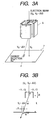
- FIG. 3(a) shows a block diagram of the electron energy filter. It is of a small size of about 10mm square having an electrode for electrostatic deflection and an electrode for magnetic deflection. It deflects an electron beam transmitting the bio specimen according to an energy to obtain energy diffusion of the electron beam on the energy selection slit 7.
- FIG. 3(b) a specific example of energy selection is shown.
- the energy of the electron beam transmitting the specimen is assumed to be a mixture of V 0 and V 0 - ⁇ V.
- ⁇ tV 1 ⁇ V/2dV 0 2
- t 1/2 of the height of the electrode for electrostatic deflection
- V 1 an applied voltage of the electrode for electrostatic deflection
- d a space between the electrodes for electrostatic deflection
- V 0 an energy of an electron beam incident upon the specimen
- ⁇ V an energy lost in the specimen.
- a slit width u of 0.010mm corresponds to an energy width of about 35eV.
- a 250eV energy distribution image can be obtained at the energy resolution of the value.
- the influence of carbon (C(280eV)) widely included in specimen embedding resin and the specimen can be removed to make the contrast of the image higher.
- Ca(350eV), N(415eV) and O (520eV) are fetched into the slit, distribution images of the respective elements can be obtained. Not only the fine structure but also the elements can be analyzed.
- the equipment controlling and image analyzing computer 14 is equipped with image analysis software identifying the species of virus and protein in a bio specimen. The analyzed result is displayed'on the image and analyzed data display screen 13.
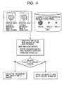
- FIG. 4 shows a flowchart of the image processing specifying the species of virus using the image analysis software. An image obtained by observing the specimen of virus is written as an observed image to the equipment controlling and image analyzing computer 14.
- the computer is equipped with a database of electron microscope images of viruses whose species are known. As shown in FIG. 4, various pathogenic viruses have a characteristic in their structures, and the sizes and structures are almost fixed between the same species of viruses.
- the database has representative images (reference images) of various viruses and its related information such as their properties and remedies.
- the image magnification and contrast of the observed image are adjusted so as to be compared with the reference image. Then, the similarity between the observed image and the reference image in the database is quantitatively analyzed by using image processing. As the image processing method, the pattern recognition method using frequency components and the correlation method are used. When the similarity is within the specified condition, the species of the observed virus and its related information are displayed. Otherwise, there is displayed that the virus was not able to be analyzed. This can automatically execute, at the observed place, identification of the species of'virus which has needed high knowledge and experience so as to make the pathological diagnosis more efficient.
- the specimen preparation micro equipment 10 automatically executes the specimen preparation when a specimen of a very small amount of a tissue or fecal matter is injected.
- FIG. 5 shows the construction of the specimen preparation micro equipment. It is chip-like with a size of about several cm square and a thickness of several mm. It is of a mechanism so as to be detachable from the specimen stage driving system part of the bio electron microscope. On the chip are formed the micro chamber, micro pump and micro fluid channel executing the preparation process using the MEMS (Micro Electro Mechanical Systems) technique. The chip is provided on its back surface with an electrode to supply a driving power of the micro chamber, micro pump and micro fluid channel from the specimen stage driving system.
- FIG. 5 shows the construction of the specimen preparation micro equipment. It is chip-like with a size of about several cm square and a thickness of several mm. It is of a mechanism so as to be detachable from the specimen stage driving system part of the bio electron microscope. On the chip are formed the micro chamber, micro pump and micro fluid channel executing the preparation
- the preparation process is as follows. First, a fecal matter dissolved in water is injected into the uppermost stream micro chamber. It is then moved to the next process in the micro fluid channel. A homogenate device performs high-speed micro-centrifugation to separate the phase containing virus. A virus purification device further conducts ultra high-speed micro-centrifugation while injecting a reagent when needed, thereby removing noises. The purified virus specimen is moved to the meshed thin plate with supporting film for electron microscope. The micro pump is used to supply the negative stain from the staining device onto the meshed thin plate. It is air-dried.
- the meshed thin plate is placed on the specimen holder 11 by the meshed thin plate transfer 9 for electron microscope.
- the meshed thin plate transfer 9 for electron microscope has at its front edge a pin detaching the meshed thin plate.
- the specimen holder 11 is moved to the electron microscope specimen chamber for observation.
- the above operation is controlled by the equipment controlling and image analyzing computer 14 and can be automatically executed.
- the present invention can automatically execute the specimen preparation which has been troublesome and has needed a skill to significantly improve the efficiency of the specimen preparation.
- the preparation condition can be fixed to bring the purified state and stained state between the specimens to the same level. As a result, the high accuracy of the examination and analysis can be achieved.
- the effects of the embodiment of the present invention are as follows.
- the observation method of a bio specimen using the electron accelerating voltage 1.2 to 4.2 times the critical electron accelerating voltage possible to transmit a specimen can significantly reduce the electron beam irradiation damage (to 1/10) as compared with the prior art and can observe the bio structure at high accuracy.
- the electron energy filter With the electron energy filter, the unstained specimen by the small and low-cost equipment construction can be observed at high contrast.
- the method for image processing analyzing similarity between the observed image of the bio specimen and the reference image in the database can automatically execute, at the observed place, identification of the species of virus which has needed high knowledge and experience.
- the specimen preparation micro equipment which can be systematic in the electron microscope body can automatically execute the specimen preparation which has been troublesome and has needed a skill to significantly improve the efficiency of the specimen preparation.
Landscapes
- Chemical & Material Sciences (AREA)
- Analytical Chemistry (AREA)
- Analysing Materials By The Use Of Radiation (AREA)
- Investigating Or Analysing Biological Materials (AREA)
- Sampling And Sample Adjustment (AREA)
Abstract
An object of the present invention is to realize
a bio electron microscope and an observation method
which can observe a bio specimen by low damage and high
contrast to perform high-accuracy image analysis, and
conduct high-throughput specimen preparation. 1) A
specimen is observed at an accelerating voltage 1.2 to
4.2 times a critical electron accelerating voltage
possible to transmit a specimen obtained under
predetermined conditions. 2) An electron energy filter
of small and simplified construction is provided
between the specimen and an electron detector for
imaging by the electron beam in a specified energy
region of the electron beams transmitting the specimen.
3) Similarity between an observed image such as virus
or protein in the specimen and a reference image such
as known virus or protein is subjected to quantitative
analysis by image processing. 4) A preparation protocol
of the bio specimen is made into a chip using an MEMS
technique, which is then mounted on a specimen stage
part of an electron microscope to conduct specimen
introduction, preparation and transfer onto a specimen
holder.
Description
The present invention relates to an electron
microscope which can irradiate an electron beam onto a
specimen and detects an electron transmitting the
specimen or a secondary electron and a reflected
electron emitted from the surface of the specimen to
obtain a magnified image. More specifically, the
present invention relates to a bio electron microscope.
To observe, in particular, a bio specimen using
an electron microscope, there are fine structure
analysis of tissues, structure analysis of protein, and
examination of virus. In recent years, various diseases
including bovine spongiform encephalopathy (BSE),
communicable disease such as HIV and HIC, food
poisoning due to 0157, and carbon fungus terrorism have
been increased. Needs for high-reliability analysis and
examination by a highly-magnified image observation
using an electron microscope are on the increase. When
noted virus and protein are fine to require high
resolution and it is desired to observe their inner
structures, a transmission electron microscope (TEM)
performing imaging by an electron transmitting a
specimen is used. A bio TEM is described in the H-7600
transmission electron microscope catalog No. HTD-040
(issued in November 2001) of Hitachi High-Technologies
Corporation. It has an electron gun, an illumination
system electron lens, a specimen holder and stage, an
imaging system electron lens, a camera, an evacuation
system, and a control system. Electron accelerating
voltages for a bio TEM are mainly 100kV and 120kV, and
may be used by lowering it to about 50kV. A bio
specimen observation procedure by the transmission
electron microscope is described in "Electron
Microscope", Vol.37, No.2, p.81-84 (2002). In the
examination of virus, a small round structured virus
having a diameter of several tens of nm causing food
poisoning is purified and concentrated from a fecal
matter to observe an image magnified tens of thousands
of times to hundreds of thousands of times, and then,
the presence or absence of virus and the species of the
virus are decided from its shape and the characteristic
of its inner structure. In addition, in the structure
analysis of protein, several magnified images of a
protein specimen extracted and purified from a tissue
are observed by tilting a specimen stage of the
electron microscope, and then, the images are subjected
to CT (computed tomography) processing to obtain a fine
three-dimensional structure in the size of several tens
of nm.
Bio specimens used for the transmission electron
microscope are broadly divided into three: 1 ○ a stained
section specimen, 2 ○ a negative stained specimen, and 3 ○
a frozen section specimen. In the stained section
specimen, the tissue of an animal or plant is cut into
a section having a thickness of several tens of nm
using a microtome equipped with a blade of diamond or
glass, which is then placed on a meshed thin plate for
electron microscope. To make the section, there are
processes such as fixation, anhydration, embedding and
cutting of the tissue. To obtain contrast corresponding
to the tissue structure in an electron microscope image,
staining the specimen is generally needed. As'a stain,
a reagent including heavy metal such as uranium acetate,
lead citrate, lead hydroxide, or lead acetate is used.
In general, the specimen is double-stained by uranium
and lead. The reason why staining is needed is that
since a main element constituting a living body are
light elements such as hydrogen, oxygen, carbon and
nitrogen, those scattering factors to an electron beam
and its difference between the elements are small so
that image contrast is very hard to provide. Stained is
protein in the tissue. The higher the concentration of
protein, the stronger protein is stained. As a result,
contrast dependent on the concentration of protein is
obtained in the electron microscope image.
In the 2 ○ negative stained specimen, a tissue or
fecal matter purified and concentrated using a reagent
and a centrifugal machine is placed on a meshed thin
plate for electron microscope. A particulate specimen
such as virus is a representative example. As a stain,
a phosphorate tungsten acid (PTA) liquid is generally
used. In this method, in the case of virus, a bank of
the stain is formed around the virus to form contrast
between the bank and the virus. In the 3 ○ frozen section
specimen, a tissue is brought into contact with a
copper block cooled by liquid helium or liquid nitrogen
to be instantaneously frozen, and is then cut in a
frozen state using a microtome equipped with a cooling
stage. Observation of a tissue structure in an active
state is aimed. Fixation and staining are not conducted,
and a cryo-electron microscope equipped with a cooling
specimen stage is used for observation. Since the
specimen is not stained, the image contrast is very low.
In the recent transmission electron microscopes,
a lens current, a shutter, and a specimen stage are
controlled by a PC (personal computer) to facilitate
operation such as focusing, photographing, and specimen
slight movement. They have functions of automatic focus,
automatic photographing, and automatic montage
(obtaining a wide area image joined by automatically
repeating specimen slight movement and photographing).
The electron microscope is not equipped with functions
of specimen preparation such as extraction,
purification, concentration and staining to observe a
specimen by the electron microscope, and of analyzing
the species of virus and a protein three-dimensional
structure from a photographed image.
The bio specimen observed by the transmission
electron microscope is susceptible to damage by
electron irradiation. A constituent constituting the
tissue contains about 85% water. It also contains 10%
protein, 2% adipo, 1.5% mineral, and 1.1% nucleic acid
which are weak to electron irradiation. When an
electron beam having an accelerating voltage of 100-120keV
is irradiated onto a specimen of a tissue of
such structure, damage such as deformation,
decomposition and destruction of the fine structure
occurs. The stained section specimen and the negative
stained specimen stained by heavy metal are rather
stronger to electron irradiation than the frozen
section specimen. The damage cannot be avoided as an
essential problem. With the damage, the bio fine
structure cannot be correctly analyzed and the accuracy
of the examination is lowered. In particular, when a
three-dimensional structure of a cell tissue is
observed by TEM, the same area of the specimen is
irradiated several tens of times while tilting the
specimen. The electron dose is very large to make the
damage significant. In this case, since the structure
is gradually changed during photographing, the images
at the respective tilt angles do not reflect the same
structure. When image processing of the three-dimensional
reconstruction is conducted using the
images, artifact occurs without obtaining any correct
three-dimensional structures.
In addition, unless the bio specimen is stained
as described above, high contrast cannot be obtained.
The fine structure may be changed by staining. It may
not be understood that how the structure observed using
the stained specimen corresponds to the original
structure. These cause erroneous analysis and lowered
examination accuracy.
The prior art electron microscope basically
observes a magnified image of fine structure.
Understanding the image, that is, extracting necessary
information must be conducted by a user. A typical
pathologic diagnosis by the electron microscope
includes specification of viral disease. The species of
virus is specified from the structure characteristic of
a viral image observed by the electron microscope. For
that, high knowledge and experience are needed. Only a
limited number of scientists can conduct this.
The recent electron microscopes are equipped
with image processing software. It can subject fast
Fourier transformation to an image photographed by a
CCD camera for frequency component analysis and conduct
grain size analysis. It, however, is only placed
supportably in order that the user can extract
necessary information.
Further, in the preparation of the bio 'specimen,
as described above, many processes such as fixation,
anhydration, embedding, cutting and staining of the
tissue are manually conducted for a long time. The
respective processes must be optimum for each desired
tissue structure for each specimen, requiring high
technology, know-how and experience. Depending on
variation in the preparation condition, quite different
electron microscope images of the same tissue may also
be obtained.
In view of the foregoing problems, an object of
the present invention is to realize a bio electron
microscope and an observation method which can observe
a bio specimen by low damage and high contrast to
perform high-accuracy image analysis, and conduct high-throughput
specimen preparation:
The followings are listed as means for achieving
the above object.
An embodiment of the present invention will be
described below.
FIG. 1 shows scanning transmission electron
microscope images (STEM images) observed using a bio
electron microscope and an observation method according
to the present invention. A specimen is a stained
section specimen of Arabidopsis (plant) and has a
specimen thickness of 100nm. In FIG. 1(a), the specimen
is observed by an incident electron beam having an
optimum accelerating voltage of 10kV, and in FIG. 1(b),
the specimen is observed by an incident electron beam
having a critical electron accelerating voltage
possible to transmit a specimen of 3kV (The definitions
of the critical electron accelerating voltage possible
to transmit a specimen and the optimum accelerating
voltage are described later.). The former can obtain
image qualities such as a resolution and contrast which
are by no means inferior to the prior art bio
transmission electron microscope (TEM) of a 100kV
accelerating voltage class. In other words, the energy
of the incident electron beam is below 1/10 to
significantly reduce damage to the specimen, and at the
same time, the image qualities can be held high. This
provides an observation method very effective for a bio
specimen susceptible to damage by electron irradiation.
The damage such as deformation, decomposition, and
destruction of the bio fine structure which has been a
problem in the prior art bio specimen can be reduced to
below 1/10. Correct analysis of a fine structure and
high-accuracy pathological examination can be conducted.
On the other hand, in the latter (FIG. 1(b)), the
resolution and contrast are both significantly
deteriorated. This is caused by the fact that the
energy of the incident electron beam is too low and
hardly transmits the specimen.

In Table 1, the stained section specimen of
Arabidopsis (plant) is observed at various electron
accelerating voltages to summarize accelerating voltage
dependence of the resolution and contrast. Data shown
in the section of the resolution are fast Fourier
transformation (FFT) images of the area indicated by □
(hollow square figure) in FIG. 1(a), and the diameter
indicated by the arrow range is in proportion to a
maximum spatial frequency, that is, an inverse number
of the resolution. The larger the numerical value, the
higher the resolution becomes. Data shown in the
section of the contrast express distributions of the
intensity (arbitrary unit) in each pixel forming the
images as the number of pixels. The half maximum full-width
of peak indicated by the arrow range corresponds
to the contrast. The larger the numerical value, the
images are formed at various intensities and the
contrast is good. The critical electron accelerating
voltage possible to transmit a specimen is defined as
an accelerating voltage when the resolution is lowered
to 3/10 or the contrast is lowered to 1/20 to an image
observed at an accelerating voltage of 30kV. The
optimum accelerating voltage is defined as a minimum
accelerating voltage which can obtain about the same
resolution and contrast as those of the image observed
at an accelerating voltage.of 30kV.
| SPECIMEN | CRITICAL ELECTRON ACCELERATING VOLTAGE POSSIBLE TO TRANSMIT A SPECIMEN (a) | OPTIMUM ACCELERATING VOLTAGE (b) | FACTOR m (b/a) |
| ARABIDOPSIS (100nm THICK) | 3.0kV | 7.5kV | 2.5 |
| MOUSE (100nm THICK) | 3.5kV | 9.0kV | 2.6 |
| MOUSE (300nm THICK) | 5.5kV | 14.0kV | 2.5 |
Table 2 shows, when bio specimens in which the
kinds of tissues and the thickness of sections are
different are observed, critical electron accelerating
voltages possible to transmit a specimen, optimum
accelerating voltages, and ratios between the optimum
accelerating voltages and the critical electron
accelerating voltages possible to transmit a specimen
as factors m. It is found that the factors m are not
dependent on the kind of the tissues and the thickness
of the sections and have a fixed value of almost 2.5.
The factors m are varied by the constituent'of the bio
specimen, the preparation method, and the observed area.
The critical electron accelerating voltage possible to
transmit a specimen is in proportion to the
transmissivity of the electron beam to the bio specimen.
The transmissivity is in proportion to penetration
depth of the electron beam. A maximum penetration depth
R is expressed by the formula of Kanaya and Okayama (K.
Kanaya and S. Okayama; J. Phys. D: Appl. Phys. 5 (1972)
43) :
R (cm) ≒ 2.76 × 10⁻¹¹ AV 5/3 / ρZ 8/9
where A: atomic mass, ρ: density, Z: atomic number, and
V: electron accelerating voltage.
V: electron accelerating voltage.
| SPECIMEN | STAINED SECTION | NEGATIVE STAINED SECTION | FROZEN SECTION |
| ELEMENTS | C(53%), O(23%), N(16%), H(7%), S(2%) | SAME AS IN THE LEFT OK | H(49.7%), O(24.9%), C(24.9%), N |
| STAINING ATOMS | Pb, U | W | NON (UNSTAINED) |
| AVERAGE ATOMIC NUMBER OF STAINING ATOMS | 87 | 74 | - |
| AVERAGE ATOMIC MASS OF STAINING ATOMS | 222.5 | 184 | - |
| DENSITY FLUCTUATION DEPENDING ON THE AREA | ±60% | ±30% | NON |
| RANGE OF FACTOR | 1.2~4.2 | 1.6~3.5 | 2.0~3.0 |
In Table 3, respective parameters of the
specimen preparation method broadly divided into three
kinds are summarized. The elements are hardly dependent
on the kind of a tissue. The frozen section specimen in
which a tissue is frozen as-is and cut is almost equal
to the elements of the living body. The stained section
specimen and the negative stained specimen subjected to
the dehydration process and the displacement process
are almost equal to the constitution of protein. The
staining atoms of the stained section specimen are lead
(element symbol Pb) and uranium (element symbol U). The
staining atom of the negative stained specimen is
tungsten (element symbol W). The frozen section
specimen is unstained and has no staining atoms. The
area of the stained section specimen observed by the
electron microscope is decided by the fine structure
noted by the user. The existence percentage (density)
of the staining atoms is dependent on the concentration
distribution of protein in the fine structure.
Depending on which fine structure is included in the
area, there may be density fluctuation of about ±60%.
In the case of the negative stained specimen, a tissue
is not directly stained and the bank of the stain is
formed around virus. The existence percentage (density)
fluctuation of the staining atoms is about ±30% of
about 1/2 of the stained section specimen. The frozen
section specimen has no staining atoms and has no
fluctuation depending on the area. From the above, the
ratio between maximum and minimum accelerating voltages
giving the fixed maximum penetration depth R is
obtained using Formula 1 to decide the range of the
factor m in consideration of an experimental values
error of ±20% from an experimental value of 2.5. The
specimens of the preparation methods are decided as
shown in the lowest, stage of Table 3. When the specimen
preparation method is known, selection of the optimum
accelerating voltage suitable for this is enabled. When
the specimen preparation method is not known, selection
of the factor m of 1.2 to 4.2 can correspond to all the
bio specimens.

Table 4 shows display screens in which the
optimum accelerating voltages of bio specimen
observation are decided by the above method. In this
example, the critical electron accelerating voltage,
possible to transmit a specimen is 3kV and the optimum
accelerating voltage is 10kV. The process to decide
both is as follows. First, the bio specimen is
introduced into a specimen chamber of the bio electron
microscope to decide an area. Here, the area near the
fine structure region noted.is selected. Next, the
electron accelerating voltage of 30kV as an initial
value is gradually lowered to photograph an electron
microscope image, writing image data to an image
analyzing computer. For the written image data,
respective quantitative values of a resolution and
contrast are sequentially obtained using fast Fourier
transformation (FFT) and intensity distribution
analysis software (The same data as that of Table 1 is
obtained.). As compared with the data at an
accelerating voltage of 30kV, when the resolution is
3/10 and the contrast is 1/20, the image observation is
stopped. The accelerating voltage at this time is the
critical electron accelerating voltage possible to
transmit a specimen. The factor m is selected in the
range shown in Table 3 according to the bio specimen
preparation method (Generally, the factor m = 2.5 is
selected.). The critical electron accelerating voltage
possible to transmit a specimen is multiplied by m to
obtain the optimum accelerating voltage. The area is
moved to the noted fine structure region noted to
observe the desired electron microscope image at the
optimum accelerating voltage, which is then written.
Very low damage observation can be achieved. When the
specimen holder of a specimen cooling type is used, it
is more effective.
The above observation process can be
automatically conducted using the bio electron
microscope of the present invention. FIG. 2 shows an
overall block diagram of the bio electron microscope of
the present invention. It has an electron illumination
system having an electron gun 1, a condenser lens 2, a
scanning coil 3, an objective lens 4 and a condenser
aperture driven with pulse motor 15, an imaging system
having a beam alignment coil 5, an electron energy
filter 6, an energy selection slit 7 and an electron
detector 8, a meshed thin plate transfer for electron
microscope 9, specimen preparation micro equipment 10,
a specimen holder 11, a recipe server for arbitrary
accelerating voltage 12, an image and analyzed data
display screen 13, and an equipment controlling and
image analyzing computer 14. The method for imaging an
electron microscope image is the same as that of the
prior art scanning transmission electron microscope
(STEM) .
When deciding the critical electron accelerating
voltage possible to transmit a specimen and the optimum
accelerating voltage, image observation is conducted
while the accelerating voltage is gradually lowered.
When the accelerating voltage is changed, the optimum
conditions of the illumination system and the imaging
system are also changed. In the present invention, the
optimum conditions at an arbitrary accelerating voltage
(emission current of the electron gun, the condenser
apertures position, and exciting current in the
respective lens) are stored into the recipe server for
arbitrary accelerating voltage 12 to control the
respective conditions to an optimum value according to
the accelerating voltage at image observation. The
accelerating voltage of 30kV as an initial value can be
automatically controlled in an arbitrary voltage step
by the equipment controlling and image analyzing
computer 14. The equipment controlling and image
analyzing computer 14 and the recipe server for
arbitrary accelerating voltage 12 are engaged with each
other. The analysis software of the resolution, and
contrast can automatically execute the above
observation process since the timing of input and
analysis execution of image data formed by a signal
from the electron detector 8 is controlled by a signal
from the equipment controlling and image analyzing
computer 14 and the recipe server for arbitrary
accelerating voltage 12.
The electron energy filter 6 is used for high-contrast
observation of the unstained specimen such as
the frozen section specimen. FIG. 3(a) shows a block
diagram of the electron energy filter. It is of a small
size of about 10mm square having an electrode for
electrostatic deflection and an electrode for magnetic
deflection. It deflects an electron beam transmitting
the bio specimen according to an energy to obtain
energy diffusion of the electron beam on the energy
selection slit 7. When only the electron beam having a
specific energy is transmitted by the energy selection
slit 7, imaging can be conducted only by the electron
beam of the energy. Using FIG. 3(b), a specific example
of energy selection is shown. The energy of the
electron beam transmitting the specimen is assumed to
be a mixture of V0 and V0-ΔV. At this time, the
electron beam having an energy of V0-ΔV is deflected
only by an angle α. α is expressed by
α = tV1 ΔV/2dV0 2
where t: 1/2 of the height of the electrode for
electrostatic deflection, V1: an applied voltage of the
electrode for electrostatic deflection, d: a space
between the electrodes for electrostatic deflection, V0:
an energy of an electron beam incident upon the
specimen, and ΔV: an energy lost in the specimen. A
deflection amount W of the energy selection slit 7 is
W = αL
where L: a distance from the center of the electrode
for electrostatic deflection to the energy selection
slit 7. When t=5mm, V1=500V, d=8mm, V0=10keV, ΔV=250eV,
and L = 185mm, α = 3.91 × 10⁻⁴ rad. and W=0.072mm. A
slit width u of 0.010mm corresponds to an energy width
of about 35eV. A 250eV energy distribution image can be
obtained at the energy resolution of the value. In this
case, the influence of carbon (C(280eV)) widely
included in specimen embedding resin and the specimen
can be removed to make the contrast of the image higher.
When Ca(350eV), N(415eV) and O (520eV) are fetched into
the slit, distribution images of the respective
elements can be obtained. Not only the fine structure
but also the elements can be analyzed.
The equipment controlling and image analyzing
computer 14 is equipped with image analysis software
identifying the species of virus and protein in a bio
specimen. The analyzed result is displayed'on the image
and analyzed data display screen 13. FIG. 4 shows a
flowchart of the image processing specifying the
species of virus using the image analysis software. An
image obtained by observing the specimen of virus is
written as an observed image to the equipment
controlling and image analyzing computer 14. The
computer is equipped with a database of electron
microscope images of viruses whose species are known.
As shown in FIG. 4, various pathogenic viruses have a
characteristic in their structures, and the sizes and
structures are almost fixed between the same species of
viruses. The database has representative images
(reference images) of various viruses and its related
information such as their properties and remedies. The
image magnification and contrast of the observed image
are adjusted so as to be compared with the reference
image. Then, the similarity between the observed image
and the reference image in the database is
quantitatively analyzed by using image processing. As
the image processing method, the pattern recognition
method using frequency components and the correlation
method are used. When the similarity is within the
specified condition, the species of the observed virus
and its related information are displayed. Otherwise,
there is displayed that the virus was not able to be
analyzed. This can automatically execute, at the
observed place, identification of the species of'virus
which has needed high knowledge and experience so as to
make the pathological diagnosis more efficient.
The specimen preparation micro equipment 10
automatically executes the specimen preparation when a
specimen of a very small amount of a tissue or fecal
matter is injected. FIG. 5 shows the construction of
the specimen preparation micro equipment. It is chip-like
with a size of about several cm square and a
thickness of several mm. It is of a mechanism so as to
be detachable from the specimen stage driving system
part of the bio electron microscope. On the chip are
formed the micro chamber, micro pump and micro fluid
channel executing the preparation process using the
MEMS (Micro Electro Mechanical Systems) technique. The
chip is provided on its back surface with an electrode
to supply a driving power of the micro chamber, micro
pump and micro fluid channel from the specimen stage
driving system. FIG. 5 shows equipment of a type
executing the specimen preparation for detecting virus
from a fecal matter specimen. The preparation process
is as follows. First, a fecal matter dissolved in water
is injected into the uppermost stream micro chamber. It
is then moved to the next process in the micro fluid
channel. A homogenate device performs high-speed micro-centrifugation
to separate the phase containing virus.
A virus purification device further conducts ultra
high-speed micro-centrifugation while injecting a
reagent when needed, thereby removing noises. The
purified virus specimen is moved to the meshed thin
plate with supporting film for electron microscope. The
micro pump is used to supply the negative stain from
the staining device onto the meshed thin plate. It is
air-dried. It can thus be observed by the electron
microscope. The meshed thin plate is placed on the
specimen holder 11 by the meshed thin plate transfer 9
for electron microscope. The meshed thin plate transfer
9 for electron microscope has at its front edge a pin
detaching the meshed thin plate. The specimen holder 11
is moved to the electron microscope specimen chamber
for observation. The above operation is controlled by
the equipment controlling and image analyzing computer
14 and can be automatically executed. The present
invention can automatically execute the specimen
preparation which has been troublesome and has needed a
skill to significantly improve the efficiency of the
specimen preparation. The preparation condition can be
fixed to bring the purified state and stained state
between the specimens to the same level. As a result,
the high accuracy of the examination and analysis can
be achieved.
The effects of the embodiment of the present
invention are as follows. The observation method of a
bio specimen using the electron accelerating voltage
1.2 to 4.2 times the critical electron accelerating
voltage possible to transmit a specimen can
significantly reduce the electron beam irradiation
damage (to 1/10) as compared with the prior art and can
observe the bio structure at high accuracy. With the
electron energy filter, the unstained specimen by the
small and low-cost equipment construction can be
observed at high contrast. The method for image
processing analyzing similarity between the observed
image of the bio specimen and the reference image in
the database can automatically execute, at the observed
place, identification of the species of virus which has
needed high knowledge and experience. The specimen
preparation micro equipment which can be systematic in
the electron microscope body can automatically execute
the specimen preparation which has been troublesome and
has needed a skill to significantly improve the
efficiency of the specimen preparation. By making use
of the above effects, high accuracy and high throughput
can be achieved in the pathological examination and the
bio fine structure analysis.
Claims (7)
- An observation method using a bio electron microscope which comprises an electron illumination system (1-4) for converging or collimating an accelerated electron beam to irradiate it onto a specimen and an imaging system (5-8) for detecting an electron transmitting the specimen or a secondary electron and a reflected electron emitted from the surface of the specimen to obtain a magnified image,
wherein said specimen is observed at a critical electron accelerating voltage allowing to transmit a specimen or at an accelerating voltage 1.2 to 4.2 times the critical electron accelerating voltage allowing to transmit a specimen obtained under predetermined conditions. - The method of claim 1, wherein said specimen is observed at an accelerating voltage for a stained section specimen 1.2 to 4.2 times the critical electron accelerating voltage allowing to transmit a specimen obtained under predetermined conditions, at an accelerating voltage for a negative stained specimen 1.6 to 3.5 times the same, and at an accelerating voltage for a frozen section specimen 2.0 to 3.0 times the same.
- The method of claim 1 or 2, wherein said critical electron accelerating voltage is determined by the following steps:photographing an observation area or an approaching area of said specimen at a low accelerating voltage below 30kV and plural kinds of accelerating voltages,comparing image qualities such as resolution and contrast of the images, anddeciding the critical electron accelerating voltage.
- A bio electron microscope comprising
an electron illumination system (1-4) for converging or collimating an accelerated electron beam to irradiate it onto a specimen, and
an imaging system (5-8) for detecting an electron transmitting the specimen or a secondary electron and a reflected electron emitted from the surface of the specimen to obtain a magnified image, wherein an electron energy filter (6) is provided between an electron detector (8) and the specimen. - The invention of any preceding claim, wherein to set an accelerating voltage of an electron beam irradiated onto said specimen to a desired value, the emission current of an electron gun (1), the exciting current of electron lenses (2, 4) in the illumination and imaging system, and/or the position of an electron beam aperture which are optimum to the accelerating voltage is held as a recipe in a controlling computer (14) .
- The invention of any preceding claim, wherein in an image analysis part and an image display part, similarity between an observed image of virus or protein included in said specimen and a reference image of known virus or protein is subjected to quantitative analysis using image processing software, and the species of virus or protein or the species of a substance in said specimen is identified to display the result.
- The invention of any preceding claim, wherein chip-like specimen preparation equipment using an MEMS (Micro Electro Mechanical Systems) technique is mounted on a specimen stage part.
Applications Claiming Priority (2)
| Application Number | Priority Date | Filing Date | Title |
|---|---|---|---|
| JP2003002724A JP2004212355A (en) | 2003-01-09 | 2003-01-09 | Bio-electron microscope and sample observation method |
| JP2003002724 | 2003-01-09 |
Publications (1)
| Publication Number | Publication Date |
|---|---|
| EP1437758A2 true EP1437758A2 (en) | 2004-07-14 |
Family
ID=32501218
Family Applications (1)
| Application Number | Title | Priority Date | Filing Date |
|---|---|---|---|
| EP20030016333 Withdrawn EP1437758A2 (en) | 2003-01-09 | 2003-07-18 | Electron microscope and observation method of biological specimen |
Country Status (3)
| Country | Link |
|---|---|
| US (1) | US6875984B2 (en) |
| EP (1) | EP1437758A2 (en) |
| JP (1) | JP2004212355A (en) |
Cited By (4)
| Publication number | Priority date | Publication date | Assignee | Title |
|---|---|---|---|---|
| CN105486553A (en) * | 2014-09-01 | 2016-04-13 | 力晶科技股份有限公司 | Preparation method of transmission electron microscope test piece |
| CN108375599A (en) * | 2018-02-02 | 2018-08-07 | 华南农业大学 | A kind of transmission electron microscope sample flaking method of microminiature Compound Eye of Insects |
| CN109136323A (en) * | 2018-09-21 | 2019-01-04 | 云南省农业科学院生物技术与种质资源研究所 | A kind of fixed diagnostic electronmicroscopy method of separation in situ of marmor upsilon plastochondria |
| CN109207552A (en) * | 2018-09-21 | 2019-01-15 | 云南省农业科学院生物技术与种质资源研究所 | A kind of fixed diagnostic electronmicroscopy method of separation in situ of small zucchini yellow mosaic virus plastochondria |
Families Citing this family (50)
| Publication number | Priority date | Publication date | Assignee | Title |
|---|---|---|---|---|
| JP4154300B2 (en) * | 2003-09-08 | 2008-09-24 | 株式会社日立ハイテクノロジーズ | Transmission electron microscope system and inspection method using the same |
| US7173259B2 (en) * | 2004-06-09 | 2007-02-06 | Taiwan Semiconductor Manufacturing Co., Ltd. | Automatically aligning objective aperture for a scanning electron microscope |
| US7312448B2 (en) * | 2005-04-06 | 2007-12-25 | Carl Zeiss Nts Gmbh | Method and apparatus for quantitative three-dimensional reconstruction in scanning electron microscopy |
| TWI275118B (en) * | 2005-12-09 | 2007-03-01 | Li Bing Huan | Sample box of electron microscope for observing a general sample/live cell |
| JP4808100B2 (en) * | 2006-07-28 | 2011-11-02 | 花王株式会社 | Evaluation method of bacterial coaggregation ability |
| US8577171B1 (en) * | 2006-07-31 | 2013-11-05 | Gatan, Inc. | Method for normalizing multi-gain images |
| US9008378B2 (en) * | 2006-12-20 | 2015-04-14 | The Board Of Trustees Of The Leland Stanford Junior University | Arrangement and imaging of biological samples |
| US7936913B2 (en) * | 2007-08-07 | 2011-05-03 | Nextslide Imaging Llc | Network image review in clinical hematology |
| EA201000427A1 (en) * | 2007-10-04 | 2010-10-29 | Хэлсион Молекулар | SEQUENCYING NUCLEIC ACID POLYMERS USING ELECTRON MICROSCOPY |
| US7659510B2 (en) * | 2008-03-28 | 2010-02-09 | Chih-Yu Chao | Cryo-charging specimen holder for electron microscope |
| US8731840B2 (en) * | 2008-10-31 | 2014-05-20 | The Invention Science Fund I, Llc | Compositions and methods for therapeutic delivery with frozen particles |
| US20100111841A1 (en) * | 2008-10-31 | 2010-05-06 | Searete Llc | Compositions and methods for surface abrasion with frozen particles |
| US8788211B2 (en) * | 2008-10-31 | 2014-07-22 | The Invention Science Fund I, Llc | Method and system for comparing tissue ablation or abrasion data to data related to administration of a frozen particle composition |
| US8545857B2 (en) * | 2008-10-31 | 2013-10-01 | The Invention Science Fund I, Llc | Compositions and methods for administering compartmentalized frozen particles |
| US8762067B2 (en) * | 2008-10-31 | 2014-06-24 | The Invention Science Fund I, Llc | Methods and systems for ablation or abrasion with frozen particles and comparing tissue surface ablation or abrasion data to clinical outcome data |
| US8725420B2 (en) | 2008-10-31 | 2014-05-13 | The Invention Science Fund I, Llc | Compositions and methods for surface abrasion with frozen particles |
| US9060931B2 (en) * | 2008-10-31 | 2015-06-23 | The Invention Science Fund I, Llc | Compositions and methods for delivery of frozen particle adhesives |
| US8849441B2 (en) * | 2008-10-31 | 2014-09-30 | The Invention Science Fund I, Llc | Systems, devices, and methods for making or administering frozen particles |
| US9072799B2 (en) * | 2008-10-31 | 2015-07-07 | The Invention Science Fund I, Llc | Compositions and methods for surface abrasion with frozen particles |
| US8603494B2 (en) * | 2008-10-31 | 2013-12-10 | The Invention Science Fund I, Llc | Compositions and methods for administering compartmentalized frozen particles |
| US20100111834A1 (en) * | 2008-10-31 | 2010-05-06 | Searete Llc, A Limited Liability Corporation Of The State Of Delaware | Compositions and methods for therapeutic delivery with frozen particles |
| US8721583B2 (en) * | 2008-10-31 | 2014-05-13 | The Invention Science Fund I, Llc | Compositions and methods for surface abrasion with frozen particles |
| US9060934B2 (en) * | 2008-10-31 | 2015-06-23 | The Invention Science Fund I, Llc | Compositions and methods for surface abrasion with frozen particles |
| US9050251B2 (en) * | 2008-10-31 | 2015-06-09 | The Invention Science Fund I, Llc | Compositions and methods for delivery of frozen particle adhesives |
| US9050317B2 (en) * | 2008-10-31 | 2015-06-09 | The Invention Science Fund I, Llc | Compositions and methods for therapeutic delivery with frozen particles |
| US8545806B2 (en) * | 2008-10-31 | 2013-10-01 | The Invention Science Fund I, Llc | Compositions and methods for biological remodeling with frozen particle compositions |
| US20100111857A1 (en) | 2008-10-31 | 2010-05-06 | Boyden Edward S | Compositions and methods for surface abrasion with frozen particles |
| US8603495B2 (en) * | 2008-10-31 | 2013-12-10 | The Invention Science Fund I, Llc | Compositions and methods for biological remodeling with frozen particle compositions |
| US8858912B2 (en) * | 2008-10-31 | 2014-10-14 | The Invention Science Fund I, Llc | Frozen compositions and methods for piercing a substrate |
| US9072688B2 (en) * | 2008-10-31 | 2015-07-07 | The Invention Science Fund I, Llc | Compositions and methods for therapeutic delivery with frozen particles |
| US8731841B2 (en) * | 2008-10-31 | 2014-05-20 | The Invention Science Fund I, Llc | Compositions and methods for therapeutic delivery with frozen particles |
| US8545855B2 (en) * | 2008-10-31 | 2013-10-01 | The Invention Science Fund I, Llc | Compositions and methods for surface abrasion with frozen particles |
| US20100111836A1 (en) * | 2008-10-31 | 2010-05-06 | Searete Llc, A Limited Liability Corporation Of The State Of Delaware | Compositions and methods for therapeutic delivery with frozen particles |
| US20100111835A1 (en) * | 2008-10-31 | 2010-05-06 | Searete Llc, A Limited Liability Corporation Of The State Of Delaware | Compositions and methods for therapeutic delivery with frozen particles |
| US8409376B2 (en) | 2008-10-31 | 2013-04-02 | The Invention Science Fund I, Llc | Compositions and methods for surface abrasion with frozen particles |
| US8551505B2 (en) * | 2008-10-31 | 2013-10-08 | The Invention Science Fund I, Llc | Compositions and methods for therapeutic delivery with frozen particles |
| US9050070B2 (en) * | 2008-10-31 | 2015-06-09 | The Invention Science Fund I, Llc | Compositions and methods for surface abrasion with frozen particles |
| US8793075B2 (en) * | 2008-10-31 | 2014-07-29 | The Invention Science Fund I, Llc | Compositions and methods for therapeutic delivery with frozen particles |
| US9060926B2 (en) * | 2008-10-31 | 2015-06-23 | The Invention Science Fund I, Llc | Compositions and methods for therapeutic delivery with frozen particles |
| US20100111831A1 (en) * | 2008-10-31 | 2010-05-06 | Searete Llc, A Limited Liability Corporation Of The State Of Delaware | Compositions and methods for surface abrasion with frozen particles |
| EP3185016B1 (en) | 2010-10-29 | 2021-06-23 | Thermo Fisher Scientific OY | System layout for an automated system for sample preparation and analysis |
| WO2013138208A1 (en) * | 2012-03-16 | 2013-09-19 | Dennis Robert T | Research on, identification of and screening for biological materials using low energy electron microscopy |
| JP5836221B2 (en) * | 2012-08-03 | 2015-12-24 | 株式会社日立ハイテクノロジーズ | Charged particle beam equipment |
| JP6309195B2 (en) * | 2013-02-18 | 2018-04-11 | 株式会社ホロン | Scanning electron microscope and inspection device |
| US10416429B2 (en) * | 2017-09-15 | 2019-09-17 | Agile Focus Designs, LLC | Dynamic focus and zoom system for use with wide-field, confocal and multiphoton microscopes |
| JP7181003B2 (en) * | 2018-05-24 | 2022-11-30 | 日本電子株式会社 | BIOLOGICAL TISSUE IMAGE PROCESSING APPARATUS AND METHOD |
| JP7181002B2 (en) * | 2018-05-24 | 2022-11-30 | 日本電子株式会社 | BIOLOGICAL TISSUE IMAGE PROCESSING SYSTEM AND MACHINE LEARNING METHOD |
| US11914131B1 (en) * | 2020-08-16 | 2024-02-27 | Gregory Dimitrenko | Optical testing system for detecting infectious disease, testing device, specimen collector and related methods |
| CN112381817B (en) * | 2020-11-30 | 2021-06-25 | 中国科学院自动化研究所 | Virus Rapid Detection System Combined with SEM Transmission Mode and Transmission Electron Microscope |
| JP7705968B2 (en) | 2022-06-29 | 2025-07-10 | デロング インストゥルメンツ エー.エス. | Multimode Low-Voltage Electron Microscope |
Family Cites Families (5)
| Publication number | Priority date | Publication date | Assignee | Title |
|---|---|---|---|---|
| US5640012A (en) * | 1995-08-25 | 1997-06-17 | Gatan, Inc. | Precision-controlled slit mechanism for electron microscope |
| DE19811395A1 (en) * | 1998-03-16 | 1999-09-23 | Deutsches Krebsforsch | Method of detecting element in sample |
| US6140645A (en) * | 1997-10-20 | 2000-10-31 | Jeol Ltd. | Transmission electron microscope having energy filter |
| JP4069545B2 (en) * | 1999-05-19 | 2008-04-02 | 株式会社日立製作所 | Electron microscope method, electron microscope array biological sample inspection method and biological inspection apparatus using the same |
| JP4312910B2 (en) * | 1999-12-02 | 2009-08-12 | 株式会社日立製作所 | Review SEM |
-
2003
- 2003-01-09 JP JP2003002724A patent/JP2004212355A/en active Pending
- 2003-07-18 EP EP20030016333 patent/EP1437758A2/en not_active Withdrawn
- 2003-07-18 US US10/621,444 patent/US6875984B2/en not_active Expired - Fee Related
Cited By (4)
| Publication number | Priority date | Publication date | Assignee | Title |
|---|---|---|---|---|
| CN105486553A (en) * | 2014-09-01 | 2016-04-13 | 力晶科技股份有限公司 | Preparation method of transmission electron microscope test piece |
| CN108375599A (en) * | 2018-02-02 | 2018-08-07 | 华南农业大学 | A kind of transmission electron microscope sample flaking method of microminiature Compound Eye of Insects |
| CN109136323A (en) * | 2018-09-21 | 2019-01-04 | 云南省农业科学院生物技术与种质资源研究所 | A kind of fixed diagnostic electronmicroscopy method of separation in situ of marmor upsilon plastochondria |
| CN109207552A (en) * | 2018-09-21 | 2019-01-15 | 云南省农业科学院生物技术与种质资源研究所 | A kind of fixed diagnostic electronmicroscopy method of separation in situ of small zucchini yellow mosaic virus plastochondria |
Also Published As
| Publication number | Publication date |
|---|---|
| US20040135083A1 (en) | 2004-07-15 |
| US6875984B2 (en) | 2005-04-05 |
| JP2004212355A (en) | 2004-07-29 |
Similar Documents
| Publication | Publication Date | Title |
|---|---|---|
| US6875984B2 (en) | Bio electron microscope and observation method of specimen | |
| US9040909B2 (en) | System and method for simultaneous detection of secondary electrons and light in a charged particle beam system | |
| EP2387062B1 (en) | Simultaneous electron detection | |
| EP2738787B1 (en) | Method of performing tomographic imaging of a sample in a charged-particle microscope | |
| JP6400283B2 (en) | Configurable charged particle device | |
| EP3531439B1 (en) | Intelligent pre-scan in scanning transmission charged particle microscopy | |
| JP2014056820A (en) | Method for performing tomography on specimen within charged particle microscope | |
| CN115997113B (en) | Method and apparatus for micromachining of samples using a focused ion beam | |
| US10483084B2 (en) | Object preparation device and particle beam device having an object preparation device and method for operating the particle beam device | |
| CN109411320A (en) | Transmit the diffraction pattern detection in charged particle microscope | |
| US20210272767A1 (en) | Method, device and system for reducing off-axial aberration in electron microscopy | |
| JP2014053304A (en) | Method for investigating and correcting aberration in charged particle lens | |
| KR20200101290A (en) | Focused ion beam impurity identification | |
| CN109841473A (en) | Transmission charged particle microscope with adjusting light beam energy spread | |
| US11593938B2 (en) | Rapid and automatic virus imaging and analysis system as well as methods thereof | |
| CN115901815A (en) | Method and system for element mapping | |
| JP2019102464A (en) | Transmission charged particle microscope with improved eels/eftem module | |
| JP4674875B2 (en) | Mass spectrometry method | |
| Fukuda et al. | Preparation of vitrified cells for TEM by cryo-FIB microscopy | |
| CN113848220A (en) | Methods of Imaging Samples Using Transmission Charged Particle Microscopy | |
| US6841776B1 (en) | Method and apparatus for high-speed inspection and review | |
| US8502142B2 (en) | Charged particle beam analysis while part of a sample to be analyzed remains in a generated opening of the sample | |
| US20240362778A1 (en) | Rapid and automatic virus imaging and analysis system as well as methods thereof | |
| JP4111778B2 (en) | Observation method of a sample partially processed into a thin film by a focused ion beam device using an electron microscope | |
| Walls | Optical and electron microscopy |
Legal Events
| Date | Code | Title | Description |
|---|---|---|---|
| PUAI | Public reference made under article 153(3) epc to a published international application that has entered the european phase |
Free format text: ORIGINAL CODE: 0009012 |
|
| AK | Designated contracting states |
Kind code of ref document: A2 Designated state(s): AT BE BG CH CY CZ DE DK EE ES FI FR GB GR HU IE IT LI LU MC NL PT RO SE SI SK TR |
|
| AX | Request for extension of the european patent |
Extension state: AL LT LV MK |
|
| STAA | Information on the status of an ep patent application or granted ep patent |
Free format text: STATUS: THE APPLICATION HAS BEEN WITHDRAWN |
|
| 18W | Application withdrawn |
Effective date: 20080624 |