EP1437582B1 - Weight detecting device for microwave ovens - Google Patents
Weight detecting device for microwave ovens Download PDFInfo
- Publication number
- EP1437582B1 EP1437582B1 EP03253991A EP03253991A EP1437582B1 EP 1437582 B1 EP1437582 B1 EP 1437582B1 EP 03253991 A EP03253991 A EP 03253991A EP 03253991 A EP03253991 A EP 03253991A EP 1437582 B1 EP1437582 B1 EP 1437582B1
- Authority
- EP
- European Patent Office
- Prior art keywords
- weight
- weight sensor
- detecting device
- free end
- microwave oven
- Prior art date
- Legal status (The legal status is an assumption and is not a legal conclusion. Google has not performed a legal analysis and makes no representation as to the accuracy of the status listed.)
- Expired - Lifetime
Links
Images


Classifications
-
- F—MECHANICAL ENGINEERING; LIGHTING; HEATING; WEAPONS; BLASTING
- F24—HEATING; RANGES; VENTILATING
- F24C—DOMESTIC STOVES OR RANGES ; DETAILS OF DOMESTIC STOVES OR RANGES, OF GENERAL APPLICATION
- F24C15/00—Details
-
- H—ELECTRICITY
- H05—ELECTRIC TECHNIQUES NOT OTHERWISE PROVIDED FOR
- H05B—ELECTRIC HEATING; ELECTRIC LIGHT SOURCES NOT OTHERWISE PROVIDED FOR; CIRCUIT ARRANGEMENTS FOR ELECTRIC LIGHT SOURCES, IN GENERAL
- H05B6/00—Heating by electric, magnetic or electromagnetic fields
- H05B6/64—Heating using microwaves
- H05B6/6447—Method of operation or details of the microwave heating apparatus related to the use of detectors or sensors
- H05B6/6464—Method of operation or details of the microwave heating apparatus related to the use of detectors or sensors using weight sensors
-
- G—PHYSICS
- G01—MEASURING; TESTING
- G01G—WEIGHING
- G01G19/00—Weighing apparatus or methods adapted for special purposes not provided for in the preceding groups
- G01G19/52—Weighing apparatus combined with other objects, e.g. furniture
- G01G19/56—Weighing apparatus combined with other objects, e.g. furniture combined with handles of tools or household implements
Definitions
- the present invention relates, in general, to weight detecting devices for microwave ovens and, more particularly, to a weight detecting device for microwave ovens which is used to detect a weight of food placed on an exterior casing of a microwave oven.
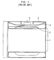
- Figure 1 is a side sectional view of a microwave oven having a conventional weight detecting device.
- a microwave oven includes an interior casing 1 and an exterior casing 3.
- a guide plate 4 having a shelf shape is provided in a space defined between a top plate 2 of the interior casing 1 and the exterior casing 3.
- the guide plate 4 is spaced apart from the top plate 2 of the interior casing 1 by a predetermined height, thus preventing heat from being transmitted from the interior casing 1 through the top plate 2 of the interior casing 1 to the guide plate 4.
- a weight sensor 5 is provided at a center of the guide plate 4.
- the weight sensor 5 has a form of a piezoelectric element which is sensitive to a variation in temperature.
- the guide plate 4 is spaced apart from the top plate 2 of the interior casing 1 by a predetermined height and to surround the weight sensor 5.
- the conventional weight detecting device has a problem that the guide plate 4 thereof surrounds the weight sensor 5, so a space to install the weight sensor 5 is increased and the size of the guide plate 4 is undesirably increased.
- the conventional weight detecting device has another problem that the weight sensor 5 thereof has the form of the piezoelectric element, so a gap between the guide plate 4 and the top plate 2 of the interior casing 1 must be increased so as to minimize the heat conduction from the interior casing 1 to the guide plate 4, thus increasing a space to install the weight sensor 5.
- EP-A 0148124 discloses a microwave oven permitting the weighing of a dish with food placed in the oven.
- a weighing support is provided comprising a weighing mechanism with a force sensor supplying an electrical signal representative of the weight of a weighted dish. This document provides basis for the pre-characterising portion of independent claim 1 appended hereto.
- JP-A-59215519 discloses a microwave oven having a weighing arrangement for weighing food placed in the oven.
- Other prior art weighing arrangements are disclosed in JP-A-57155035 and GB2245993 .
- a weight detecting device for a microwave oven comprising: a weight detecting unit comprising a weight sensor supported at an end thereof, and detecting a weight according to a force applied to a free end thereof; a support unit to support the weight sensor; a force transmitting unit mounted to the free end of the weight sensor so as to transmit the force to the free end of the weight sensor; and a food seating unit, wherein the weight detecting unit detects the weight according to the force generated by food placed on the food seating unit; characterised by: the support unit supporting the weight sensor at a position spaced apart from a top plate of an interior casing of the microwave oven by a predetermined height, the support unit comprising a support bracket being mounted to the top plate of the interior casing; and the food seating unit being provided on a top plate of an exterior casing of the microwave oven.
- FIG 2 is a perspective view of a microwave oven having a weight detecting device according to an embodiment of the present invention.
- a microwave oven 8 includes a machine room 10 in which a magnetron (not shown) irradiating microwaves is installed.
- the microwave oven 8 further includes an interior casing 11 partitioned from the machine room 10.
- the magnetron irradiates microwaves into the interior casing 11.
- An exterior casing 12 surrounds the interior casing 11 and defines the machine room 10 therein and maintains a predetermined gap between the interior and exterior casings 11 and 12.
- a control panel 13 is mounted to a front of the machine room 10 to control an operation of the microwave oven 8.
- a door 14 is mounted to a front of the interior casing 11 so as to selectively open or close the interior casing 11.
- a weight detecting device 15 is provided at a space between a top plate 20 (see Figure 3) of the interior casing 11 and a top plate 25 (see Figure 3) of the exterior casing 12.
- the weight detecting device 15 includes a weight detecting unit 40 and a support unit 41.
- the weight detecting unit 40 operates to detect a weight of food which is placed on the exterior casing 12.
- the support unit 41 operates to support the weight detecting unit 40 at a position spaced apart from the top plate 20 of the interior casing 11 by a predetermined height preventing heat from being transmitted from the interior casing 11 to the weight detecting unit 40.
- the weight detecting unit 40 detects the weight of the food placed on a food seating unit 16 which is provided on the exterior casing 12.
- FIG 3 is a partial sectional view of the microwave oven 8 including the weight detecting device illustrated in Figure 2.
- Figure 4 is an exploded perspective view of the weight detecting device illustrated in Figure 3.
- a weight sensor 22 has a bar shape of a predetermined length, and is supported at an end thereof by a support bracket 21. Further, a shaft 23 acting as a force transmitting unit is mounted to a free end of the weight sensor 22 so as to be perpendicular to the free end to transmit a force applied to the food seating unit 16 of the exterior casing 12 to the free end of the weight sensor 22.
- Screw holes 22b are provided at a fixed end of the weight sensor 22 so that the weight sensor 22 is screwed to the support bracket 21.
- a screw hole 22c is provided at the free end of the weight sensor 22 to receive the shaft 23.
- the shaft 23 may be externally threaded, while the screw hole 22c may be internally threaded, so that the shaft 23 is tightened to the screw hole 22c.
- at least one heat dissipating hole 22a is provided at a predetermined portion of the weight sensor 22 to allow the weight sensor 22 to be easily bent in response to a load applied to the free end of the weight sensor 22 and to dissipate heat.
- Upper and lower sensing elements 22d are provided on upper and lower surfaces of a central portion of the weight sensor 22, respectively.
- the weight sensor 22 Since the weight sensor 22 is made of an elastic material, the weight sensor 22 is bent by a force applied to the shaft 23 mounted to the free end of the weight sensor 22. A weight of the food is detected based on a variation in the internal resistance of the sensing elements 22d which are varied according to a displacement of the bent weight sensor 22.
- the support bracket 21 is made of steel, and has two fixing parts 27 so as to be screwed to the top plate 20 of the interior casing 11.
- a screw hole 21a is formed at a predetermined position of each of the fixing parts 27 so that the support bracket 21 is screwed by screws 26 to the top plate 20 of the interior casing 11.
- the support bracket 21 has a support part 21c which is upwardly bent from the fixing parts 27, thus allowing the weight sensor 22 to be supported at the position spaced apart from the top plate 20 of the interior casing 11 by the predetermined height.
- the support part 21c is provided with screw holes 21b corresponding to the screw holes 22b which are provided at the fixed end of the weight sensor 22.
- the shaft 23 is provided with a support plate 23a and a rod 23b.
- the support plate 23a has a predetermined area to be inserted into the food seating unit 16.
- the rod 23b concentrates the force applied to the support plate 23a on the free end of the weight sensor 22.
- the rod 23b is tightened to the screw hole 22c of the weight sensor 22.
- the food seating unit 16 includes a tray bracket 28, a rubber packing 29, and a locking ring 30.
- the tray bracket 28 is integrated with the top plate 25 of the exterior casing 12.
- the rubber packing 29 is mounted to the tray bracket 28, thus allowing the food to be seated on the food seating unit 16.
- the locking ring 30 locks the rubber packing 29 to the tray bracket 28.
- a shaft receiving hole 28a is provided at a predetermined position of the tray bracket 28 to receive the support plate 23a of the shaft 23 such that the support plate 23a comes into contact with a lower surface of the rubber packing 29.
- At least one locking slit 28b is formed at at least one position along an outer circumference of the tray bracket 28 to lock the rubber packing 29 to the tray bracket 28.
- Locking projections 30a provided along an edge of the locking ring 30 are fitted into the locking slits 28b to lock the rubber packing 29 to the tray bracket 28.
- the screw holes 21a provided on the fixing parts 27 of the support bracket 21 are aligned with screw holes 20a of the top plate 20 of the interior casing 11.
- the screws 26 are tightened to the aligned screw holes 20a and 21a to mount the support bracket 21 to the top plate 20 of the interior casing 11.
- the screw holes 22b of the weight sensor 22 are aligned with the screw holes 21b of the support bracket 21.
- only an end of the weight sensor 22 is supported by the support bracket 21 so as to be spaced apart from the top plate 20 of the interior casing 11 by a predetermined height, thus allowing a size of the support bracket 21 to be reduced.
- the weight sensor 22 has a cantilever beam structure which is effectively resistant to temperature variation, and is supported by the support part 21c of the support bracket 21 to minimize heat conduction from the interior casing 11 through the top plate 20 of the interior casing 11 to the weight sensor 22 preventing the weight sensor 22 from being affected by a temperature of the interior casing 11.
- the support bracket 21 is mounted to a position of the top plate 20 of the interior casing 11, a space to install the weight sensor 22 is considerably reduced. Heat transmitted through the support bracket 21 to the weight sensor 22 is dissipated through the heat dissipating holes 22a which are provided at the predetermined portion of the weight sensor 22.
- the rod 23b of the shaft 23 is tightened to the screw hole 22c which is formed at the free end of the weight sensor 22.
- An end of the weight sensor 22 is supported by the support bracket 21, so the weight sensor 22 is bent and a position thereof is varied when the force is applied through the shaft 23 to the free end of the weight sensor 22.
- the support plate 23a of the shaft 23 is inserted into the shaft receiving hole 28a of the tray bracket 28, which is provided on the top plate 25 of the exterior casing 12, so that the shaft 23 is coupled to the tray bracket 28.
- the rubber packing 29 is mounted to the tray bracket 28 using the locking ring 30.
- a weight detecting device for microwave ovens in which a weight sensor of a cantilever beam structure is effectively resistant to temperature variation, to minimize a space to install the weight sensor and to prevent the weight sensor from being affected by a variation in temperature.
- the present invention provides a weight detecting device for microwave ovens, which is designed such that only a part of a weight sensor is supported by a support bracket, thus allowing a construction of the support bracket to be simple, therefore minimizing a space to install the weight sensor.
Landscapes
- Physics & Mathematics (AREA)
- Electromagnetism (AREA)
- General Physics & Mathematics (AREA)
- Engineering & Computer Science (AREA)
- Chemical & Material Sciences (AREA)
- Combustion & Propulsion (AREA)
- Mechanical Engineering (AREA)
- General Engineering & Computer Science (AREA)
- Electric Ovens (AREA)
Description
- The present invention relates, in general, to weight detecting devices for microwave ovens and, more particularly, to a weight detecting device for microwave ovens which is used to detect a weight of food placed on an exterior casing of a microwave oven.
- Figure 1 is a side sectional view of a microwave oven having a conventional weight detecting device.
- As illustrated in Figure 1, a microwave oven includes an interior casing 1 and an exterior casing 3. A
guide plate 4 having a shelf shape is provided in a space defined between atop plate 2 of the interior casing 1 and the exterior casing 3. In the microwave oven of Figure 1, theguide plate 4 is spaced apart from thetop plate 2 of the interior casing 1 by a predetermined height, thus preventing heat from being transmitted from the interior casing 1 through thetop plate 2 of the interior casing 1 to theguide plate 4. Aweight sensor 5 is provided at a center of theguide plate 4. - In a conventional weight detecting device, the
weight sensor 5 has a form of a piezoelectric element which is sensitive to a variation in temperature. Thus, to minimize a heat conduction from the interior casing 1 to theguide plate 4, theguide plate 4 is spaced apart from thetop plate 2 of the interior casing 1 by a predetermined height and to surround theweight sensor 5. - However, the conventional weight detecting device has a problem that the
guide plate 4 thereof surrounds theweight sensor 5, so a space to install theweight sensor 5 is increased and the size of theguide plate 4 is undesirably increased. - The conventional weight detecting device has another problem that the
weight sensor 5 thereof has the form of the piezoelectric element, so a gap between theguide plate 4 and thetop plate 2 of the interior casing 1 must be increased so as to minimize the heat conduction from the interior casing 1 to theguide plate 4, thus increasing a space to install theweight sensor 5. -
EP-A 0148124 discloses a microwave oven permitting the weighing of a dish with food placed in the oven. A weighing support is provided comprising a weighing mechanism with a force sensor supplying an electrical signal representative of the weight of a weighted dish. This document provides basis for the pre-characterising portion of independent claim 1 appended hereto. -
JP-A-59215519 JP-A-57155035 GB2245993 - It is an aim of the present invention to provide a weight detecting device for microwave ovens, which is designed to minimize a space to install a weight sensor and/or to minimize heat conduction from an interior casing through a top plate of the interior casing to the weight sensor.
- Other aims and/or advantages of the invention will be set forth in part in the description which follows and, in part, will be obvious from the description, or may be learned by practice of the invention.
- According to the present invention there is provided an apparatus and method as set forth in the appended claims. Preferred features of the invention will be apparent from the dependent claims, and the description which follows.
- In one aspect of the present invention there is provided a weight detecting device for a microwave oven, comprising: a weight detecting unit comprising a weight sensor supported at an end thereof, and detecting a weight according to a force applied to a free end thereof; a support unit to support the weight sensor; a force transmitting unit mounted to the free end of the weight sensor so as to transmit the force to the free end of the weight sensor; and a food seating unit, wherein the weight detecting unit detects the weight according to the force generated by food placed on the food seating unit; characterised by: the support unit supporting the weight sensor at a position spaced apart from a top plate of an interior casing of the microwave oven by a predetermined height, the support unit comprising a support bracket being mounted to the top plate of the interior casing; and the food seating unit being provided on a top plate of an exterior casing of the microwave oven.
- For a better understanding of the invention, and to show how embodiments of the same may be carried into effect, reference will now be made, by way of example, to the accompanying diagrammatic drawings in which:
- Figure 1 is a side sectional view of a microwave oven having a conventional weight detecting device;
- Figure 2 is a perspective view of a microwave oven having a weight detecting device according to an embodiment of the present invention;
- Figure 3 is a partial sectional view of the microwave oven including weight detecting device illustrated in Figure 2; and
- Figure 4 is an exploded perspective view of the weight detecting device illustrated in Figure 3.
- Figure 2 is a perspective view of a microwave oven having a weight detecting device according to an embodiment of the present invention. As illustrated in Figure 2, a
microwave oven 8 includes amachine room 10 in which a magnetron (not shown) irradiating microwaves is installed. Themicrowave oven 8 further includes aninterior casing 11 partitioned from themachine room 10. The magnetron irradiates microwaves into theinterior casing 11. Anexterior casing 12 surrounds theinterior casing 11 and defines themachine room 10 therein and maintains a predetermined gap between the interior andexterior casings - A
control panel 13 is mounted to a front of themachine room 10 to control an operation of themicrowave oven 8. Adoor 14 is mounted to a front of theinterior casing 11 so as to selectively open or close theinterior casing 11. - A
weight detecting device 15 is provided at a space between a top plate 20 (see Figure 3) of theinterior casing 11 and a top plate 25 (see Figure 3) of theexterior casing 12. Theweight detecting device 15 includes aweight detecting unit 40 and asupport unit 41. Theweight detecting unit 40 operates to detect a weight of food which is placed on theexterior casing 12. Thesupport unit 41 operates to support theweight detecting unit 40 at a position spaced apart from thetop plate 20 of theinterior casing 11 by a predetermined height preventing heat from being transmitted from theinterior casing 11 to theweight detecting unit 40. Theweight detecting unit 40 detects the weight of the food placed on afood seating unit 16 which is provided on theexterior casing 12. - Figure 3 is a partial sectional view of the
microwave oven 8 including the weight detecting device illustrated in Figure 2. Figure 4 is an exploded perspective view of the weight detecting device illustrated in Figure 3. - As illustrated in Figures 3 and 4, a
weight sensor 22 has a bar shape of a predetermined length, and is supported at an end thereof by asupport bracket 21. Further, ashaft 23 acting as a force transmitting unit is mounted to a free end of theweight sensor 22 so as to be perpendicular to the free end to transmit a force applied to thefood seating unit 16 of theexterior casing 12 to the free end of theweight sensor 22. -
Screw holes 22b are provided at a fixed end of theweight sensor 22 so that theweight sensor 22 is screwed to thesupport bracket 21. A screw hole 22c is provided at the free end of theweight sensor 22 to receive theshaft 23. Theshaft 23 may be externally threaded, while the screw hole 22c may be internally threaded, so that theshaft 23 is tightened to the screw hole 22c. Further, at least oneheat dissipating hole 22a is provided at a predetermined portion of theweight sensor 22 to allow theweight sensor 22 to be easily bent in response to a load applied to the free end of theweight sensor 22 and to dissipate heat. Upper andlower sensing elements 22d are provided on upper and lower surfaces of a central portion of theweight sensor 22, respectively. When theweight sensor 22 is bent in response to the load applied to the free end of theweight sensor 22, the upper surface having theupper sensing element 22d is expanded while the lower surface having thelower sensing element 22d contracts, so an internal resistance of the upper andlower sensing elements 22d is varied. - Since the
weight sensor 22 is made of an elastic material, theweight sensor 22 is bent by a force applied to theshaft 23 mounted to the free end of theweight sensor 22. A weight of the food is detected based on a variation in the internal resistance of thesensing elements 22d which are varied according to a displacement of thebent weight sensor 22. - Further, the
support bracket 21 is made of steel, and has twofixing parts 27 so as to be screwed to thetop plate 20 of theinterior casing 11. Ascrew hole 21a is formed at a predetermined position of each of thefixing parts 27 so that thesupport bracket 21 is screwed byscrews 26 to thetop plate 20 of theinterior casing 11. Thesupport bracket 21 has a support part 21c which is upwardly bent from thefixing parts 27, thus allowing theweight sensor 22 to be supported at the position spaced apart from thetop plate 20 of theinterior casing 11 by the predetermined height. The support part 21c is provided withscrew holes 21b corresponding to thescrew holes 22b which are provided at the fixed end of theweight sensor 22. - The
shaft 23 is provided with asupport plate 23a and arod 23b. Thesupport plate 23a has a predetermined area to be inserted into thefood seating unit 16. Therod 23b concentrates the force applied to thesupport plate 23a on the free end of theweight sensor 22. Therod 23b is tightened to the screw hole 22c of theweight sensor 22. - Further, the
food seating unit 16 includes atray bracket 28, arubber packing 29, and alocking ring 30. Thetray bracket 28 is integrated with thetop plate 25 of theexterior casing 12. Therubber packing 29 is mounted to thetray bracket 28, thus allowing the food to be seated on thefood seating unit 16. Thelocking ring 30 locks the rubber packing 29 to thetray bracket 28. Ashaft receiving hole 28a is provided at a predetermined position of thetray bracket 28 to receive thesupport plate 23a of theshaft 23 such that thesupport plate 23a comes into contact with a lower surface of therubber packing 29. At least onelocking slit 28b is formed at at least one position along an outer circumference of thetray bracket 28 to lock therubber packing 29 to thetray bracket 28.Locking projections 30a provided along an edge of thelocking ring 30 are fitted into thelocking slits 28b to lock therubber packing 29 to thetray bracket 28. - The process of assembling the weight detecting device for microwave ovens of Figure 3 will be described in the following with reference to Figure 4.
- First, the
screw holes 21a provided on the fixingparts 27 of thesupport bracket 21 are aligned withscrew holes 20a of thetop plate 20 of theinterior casing 11. Next, thescrews 26 are tightened to the alignedscrew holes support bracket 21 to thetop plate 20 of theinterior casing 11. - To mount the
weight sensor 22 to thesupport bracket 21 usingscrews 37, the screw holes 22b of theweight sensor 22 are aligned with the screw holes 21b of thesupport bracket 21. In this case, only an end of theweight sensor 22 is supported by thesupport bracket 21 so as to be spaced apart from thetop plate 20 of theinterior casing 11 by a predetermined height, thus allowing a size of thesupport bracket 21 to be reduced. Further, theweight sensor 22 has a cantilever beam structure which is effectively resistant to temperature variation, and is supported by the support part 21c of thesupport bracket 21 to minimize heat conduction from theinterior casing 11 through thetop plate 20 of theinterior casing 11 to theweight sensor 22 preventing theweight sensor 22 from being affected by a temperature of theinterior casing 11. - Further, since the
support bracket 21 is mounted to a position of thetop plate 20 of theinterior casing 11, a space to install theweight sensor 22 is considerably reduced. Heat transmitted through thesupport bracket 21 to theweight sensor 22 is dissipated through theheat dissipating holes 22a which are provided at the predetermined portion of theweight sensor 22. - After the
weight sensor 22 is mounted to thesupport bracket 21, therod 23b of theshaft 23 is tightened to the screw hole 22c which is formed at the free end of theweight sensor 22. An end of theweight sensor 22 is supported by thesupport bracket 21, so theweight sensor 22 is bent and a position thereof is varied when the force is applied through theshaft 23 to the free end of theweight sensor 22. - After the
shaft 23 is mounted to theweight sensor 22, thesupport plate 23a of theshaft 23 is inserted into theshaft receiving hole 28a of thetray bracket 28, which is provided on thetop plate 25 of theexterior casing 12, so that theshaft 23 is coupled to thetray bracket 28. The rubber packing 29 is mounted to thetray bracket 28 using thelocking ring 30. Thus, when a load, such as food, placed on the rubber packing 29 is transmitted through theshaft 23 to the free end of theweight sensor 22, theweight sensor 22 is bent and the resistance of thesensing elements 22d of theweight sensor 22 is varied, so a weight of the food is detected. - As is apparent from the above description, a weight detecting device for microwave ovens is provided in which a weight sensor of a cantilever beam structure is effectively resistant to temperature variation, to minimize a space to install the weight sensor and to prevent the weight sensor from being affected by a variation in temperature.
- Further, the present invention provides a weight detecting device for microwave ovens, which is designed such that only a part of a weight sensor is supported by a support bracket, thus allowing a construction of the support bracket to be simple, therefore minimizing a space to install the weight sensor.
- Although a few preferred embodiments have been shown and described, it will be appreciated by those skilled in the art that various changes and modifications might be made without departing from the scope of the invention, as defined in the appended claims.
Claims (21)
- A weight detecting device for a microwave oven, comprising:a weight detecting unit (40) comprising a weight sensor (22) supported at an end thereof, and detecting a weight according to a force applied to a free end thereof;a support unit (41) to support the weight sensor (22);a force transmitting unit (23) mounted to the free end of the weight sensor (22) so as to transmit the force to the free end of the weight sensor (22); anda food seating unit (16), wherein the weight detecting unit (40) detects the weight according to the force generated by food placed on the food seating unit (16);characterised by:the support unit (41) supporting the weight sensor (22) at a position spaced apart from a top plate (20) of an interior casing (11) of the microwave oven by a predetermined height, the support unit (41) comprising a support bracket (21) being mounted to the top plate (20) of the interior casing (11); andthe food seating unit (16) being provided on a top plate (25) of an exterior casing (12) of the microwave oven.
- The weight detecting device of claim 1, wherein the support bracket (21) has a support part (21c) which is upwardly bent from two fixing parts (27).
- The weight detecting device according to claim 1 or 2, wherein the food seating unit (16) further comprises:a tray bracket (28) integrated with the top plate (25) of the exterior casing (12);a rubber packing (29) mounted to the tray bracket (28) ; anda locking ring (30) to lock the rubber packing (29) to the tray bracket (28).
- The weight detecting device according to claim 1, 2 or 3, wherein the weight sensor (22) is provided with at least one heat dissipating hole (22a).
- The weight detecting device according to any preceding claim, wherein the force transmitting unit (23) comprises:a support plate (23a) having a predetermined area; anda rod (23b), provided adjacent to the support plate (23a), to concentrate the force applied to the support plate (23a) on the free end of the weight sensor (22).
- The weight detecting device of claim 1, wherein:the weight detecting unit (40) comprising a beam fixed at the end thereof to the support unit (41), to detect the weight placed on the free end of the beam based on a deflection of the beam.
- The weight detecting device of claim 1, wherein:the weight detecting unit (40) comprises a cantilever beam (22) for which a displacement of the free end thereof is substantially resistant to temperature variation, the weight detecting unit being adapted to detect the weight placed on the free end of the cantilever beam (22) based on the displacement of the free end thereof.
- The weight detecting device of claim 1, wherein:the weight detecting unit (40) comprises a cantilever beam (22) for which a displacement of the free end thereof is substantially resistant to temperature variation, and being adapted to detect the weight according to a force applied to the free end of the cantilever beam (22) causing the displacement of the free end of the cantilever beam (22).
- The weight detecting device according to claim 1, wherein the transmitting unit (23) comprises:a shaft (23) positioned perpendicular to the free end of the weight sensor (22) to transmit the external force applied to a food seating unit (16) to the free end of the weight sensor (22).
- The weight detecting device according to claim 9, wherein the weight sensor (22) comprises:a beam (22) supported by the support unit (41) and communicating with the shaft (23) of the transmitting unit (23); andone or more heat dissipating holes (22a) formed in the beam at a predetermined portion of the beam so as to allow the beam to bend in response to the external force applied to the free end of the weight sensor (22) and to dissipate heat generated by the microwave oven.
- The weight detecting device according to any of claims 1 to 3, 9 or 10, wherein the weight sensor (22) further comprises:upper and lower sensing elements (22d) provided on each of upper and lower surfaces of a central portion of the beam of the weight sensor (22), respectively, such that a variation, according to a displacement of the beam of the weight sensor (22), in the internal resistance of the upper and lower sensing elements (22d) is detected.
- The weight detecting device according to any of claims 1 to 3 or 9 to 11, wherein, when the weight sensor (22) is bent in response to the load applied to the free end of the weight sensor (22), the upper surface of the beam of the weight sensor (22) having the upper sensing element expands while the lower surface of the beam of the weight sensor (22) having the lower sensing element contracts to change an internal resistance of the upper and low sensing elements.
- The weight detecting device according to any of claims 1 to 3 or 9 to 12 wherein the weight sensor (22) is made of an elastic material to bend by the external force applied to the shaft (23).
- A microwave oven according to any of claims 1 to 3 or 5.
- The microwave according to claim 14, wherein the weight sensor (22) comprises:a beam supported by the support unit (41) and communicating with the shaft (23) of the transmitting unit (23); andone or more heat dissipating holes formed in the beam at a predetermined portion of the beam so as to allow the beam to bend in response to the external force applied to the free end of the weight sensor (22) and to dissipate heat generated by the microwave oven.
- The microwave oven according to claim 14 or 15, wherein the weight sensor (22) comprises:upper and lower sensing elements (22d) provided on each of upper and lower surfaces of a central portion of the beam of the weight sensor (22), respectively, such that a variation, according to a displacement of the beam of the weight sensor (22), in the internal resistance of the upper and lower sensing elements (22d) is detected.
- The microwave oven according to any of claims 14 to 16, wherein, when the weight sensor (22) is bent in response to the load applied to the free end of the weight sensor (22), the upper surface of the beam of the weight sensor (22) having the upper sensing element expands while the lower surface of the beam of the weight sensor (22) having the lower sensing element contracts to change an internal resistance of the upper and low sensing elements.
- The microwave oven according to any of claims 14 to 17, wherein the weight sensor (22) is made of an elastic material to bend by the external force applied to the shaft (23).
- A microwave oven having a weight detecting device according to any of claims 6-8.
- A method of detecting a weight of food using a microwave oven, comprising:mounting a support unit(41) to a top plate (20) of an interior casing (11);spacing apart a weight sensor (22) of the weight detecting device from a top of the microwave oven by a predetermined height;fixing one end of a weight detecting device of the microwave oven;deflecting a free end of the weight detecting device by the weight of the food placed thereon;detecting the weight of the food placed on a food seating unit provided on a top plate of an exterior casing of the microwave oven according to a deflection result of the free end of the weight detecting device; anddissipating heat generated by the microwave oven in the weight detecting device so as to substantially prevent a variation in the detected weight by heat generated by the microwave oven.
- The method according to claim 22, wherein the dissipating of heat generated comprises:forming, in the weight sensor (22), one or more heat dissipating holes to dissipate the heat generated by the microwave oven.
Applications Claiming Priority (2)
| Application Number | Priority Date | Filing Date | Title |
|---|---|---|---|
| KR2003001577 | 2003-01-10 | ||
| KR1020030001577A KR20040064747A (en) | 2003-01-10 | 2003-01-10 | Weight detecting apparatus for microwave oven |
Publications (3)
| Publication Number | Publication Date |
|---|---|
| EP1437582A2 EP1437582A2 (en) | 2004-07-14 |
| EP1437582A3 EP1437582A3 (en) | 2006-05-24 |
| EP1437582B1 true EP1437582B1 (en) | 2007-08-01 |
Family
ID=32501496
Family Applications (1)
| Application Number | Title | Priority Date | Filing Date |
|---|---|---|---|
| EP03253991A Expired - Lifetime EP1437582B1 (en) | 2003-01-10 | 2003-06-25 | Weight detecting device for microwave ovens |
Country Status (6)
| Country | Link |
|---|---|
| US (1) | US6911634B2 (en) |
| EP (1) | EP1437582B1 (en) |
| JP (1) | JP3939285B2 (en) |
| KR (1) | KR20040064747A (en) |
| CN (1) | CN1283954C (en) |
| DE (1) | DE60315250T2 (en) |
Families Citing this family (6)
| Publication number | Priority date | Publication date | Assignee | Title |
|---|---|---|---|---|
| CN103196535B (en) * | 2013-03-29 | 2014-12-24 | 杭州福斯达实业集团有限公司 | Weighing instrument |
| CN111743392B (en) * | 2019-03-29 | 2025-03-07 | 华帝股份有限公司 | Steam cooking device with weighing function |
| CN111839252B (en) * | 2019-04-30 | 2023-12-15 | 华帝股份有限公司 | Self-weighting cooking equipment with heat dissipation function |
| CN110514329A (en) * | 2019-08-08 | 2019-11-29 | 西安中星测控有限公司 | A kind of passive two-dimensional code load transducer and preparation method thereof |
| CN112540022A (en) * | 2020-12-02 | 2021-03-23 | 中触媒新材料股份有限公司 | High-throughput evaluation device for catalyst and adsorbent and application method |
| US12389919B1 (en) * | 2024-03-29 | 2025-08-19 | Meta 9 Limited | Smart infusion system, device, and method |
Family Cites Families (10)
| Publication number | Priority date | Publication date | Assignee | Title |
|---|---|---|---|---|
| JPS57155035A (en) * | 1981-03-20 | 1982-09-25 | Matsushita Electric Ind Co Ltd | Microwave heater |
| JPS57155034A (en) * | 1981-03-20 | 1982-09-25 | Matsushita Electric Ind Co Ltd | Microwave heater |
| JPS5860125A (en) * | 1981-10-05 | 1983-04-09 | Matsushita Electric Ind Co Ltd | Heating cooker |
| JPS5944527A (en) * | 1982-09-07 | 1984-03-13 | Toshiba Corp | High frequency heating device |
| JPS59215519A (en) * | 1983-05-24 | 1984-12-05 | Toshiba Corp | Cooking utensil |
| EP0148124A3 (en) * | 1983-12-21 | 1986-04-02 | S.C.A.I.M.E. | Weighing device for a microwave furnace |
| JPH03221727A (en) * | 1990-01-29 | 1991-09-30 | Brother Ind Ltd | Method for cooking raw potatoes with skin in a microwave oven and its apparatus |
| KR960011448B1 (en) * | 1993-10-26 | 1996-08-22 | 대우전자 주식회사 | Microwave integrated microwave oven |
| KR960011448A (en) | 1994-09-23 | 1996-04-20 | 석진철 | Battery status detector |
| US5591261A (en) * | 1994-11-30 | 1997-01-07 | Too Sweet, Ltd. | Electromechanical cake decorating apparatus |
-
2003
- 2003-01-10 KR KR1020030001577A patent/KR20040064747A/en not_active Ceased
- 2003-06-02 CN CNB03138434XA patent/CN1283954C/en not_active Expired - Fee Related
- 2003-06-25 EP EP03253991A patent/EP1437582B1/en not_active Expired - Lifetime
- 2003-06-25 DE DE60315250T patent/DE60315250T2/en not_active Expired - Lifetime
- 2003-09-29 US US10/671,629 patent/US6911634B2/en not_active Expired - Lifetime
- 2003-11-12 JP JP2003383078A patent/JP3939285B2/en not_active Expired - Fee Related
Non-Patent Citations (1)
| Title |
|---|
| None * |
Also Published As
| Publication number | Publication date |
|---|---|
| JP3939285B2 (en) | 2007-07-04 |
| US20040134902A1 (en) | 2004-07-15 |
| DE60315250T2 (en) | 2008-02-21 |
| CN1283954C (en) | 2006-11-08 |
| EP1437582A3 (en) | 2006-05-24 |
| JP2004219055A (en) | 2004-08-05 |
| KR20040064747A (en) | 2004-07-21 |
| EP1437582A2 (en) | 2004-07-14 |
| DE60315250D1 (en) | 2007-09-13 |
| CN1517594A (en) | 2004-08-04 |
| US6911634B2 (en) | 2005-06-28 |
Similar Documents
| Publication | Publication Date | Title |
|---|---|---|
| US6911634B2 (en) | Weight detecting device for microwave ovens | |
| JP3546338B2 (en) | Microwave oven weight sensing device | |
| EP2144007B1 (en) | A supporting bracket for supporting a radiant heating device above a bottom panel of a cooking hob | |
| EP2681924B1 (en) | Sub-rack mounting bracket and assembly | |
| US6098941A (en) | Mounting apparatus for components/assemblies | |
| AU2018424296B2 (en) | Washing machine | |
| CN111983256B (en) | Acceleration sensor core unit and method for preventing substrate on which acceleration sensor is mounted from bending | |
| CA2030733C (en) | Microwave cooking apparatus | |
| JP2848822B1 (en) | Microwave oven weight sensor tuning device | |
| EP3910300B1 (en) | Integrated high-precision weighing module with reduced thermal gradient | |
| US6091029A (en) | Weight sensing device for a microwave oven | |
| JPH05118554A (en) | Cooker weight sensor | |
| CN1175211C (en) | heating cooker | |
| JPH11125428A (en) | Microwave oven weight sensor fixing device | |
| KR102925353B1 (en) | Haptic vibration compensation method using acceleration sensor and haptic switch with haptic vibration compensation function using the same | |
| KR960009854Y1 (en) | Capacitance Adjustment Structure of Microwave Weight Sensor | |
| EP3518071B1 (en) | A display mount | |
| JP4206283B2 (en) | Cooker | |
| KR970000191Y1 (en) | Flat spring structure of weight sensor | |
| KR19990054011A (en) | microwave | |
| JP2000283469A (en) | High frequency heating equipment | |
| KR20020057123A (en) | The mounting structure of control panel for microwave oven | |
| JP2000104928A (en) | Weight detector for cooking device | |
| JPS6053725A (en) | Mounting device for thermostat | |
| JPH0633255U (en) | sensor |
Legal Events
| Date | Code | Title | Description |
|---|---|---|---|
| PUAI | Public reference made under article 153(3) epc to a published international application that has entered the european phase |
Free format text: ORIGINAL CODE: 0009012 |
|
| 17P | Request for examination filed |
Effective date: 20030718 |
|
| AK | Designated contracting states |
Kind code of ref document: A2 Designated state(s): AT BE BG CH CY CZ DE DK EE ES FI FR GB GR HU IE IT LI LU MC NL PT RO SE SI SK TR |
|
| AX | Request for extension of the european patent |
Extension state: AL LT LV MK |
|
| PUAL | Search report despatched |
Free format text: ORIGINAL CODE: 0009013 |
|
| AK | Designated contracting states |
Kind code of ref document: A3 Designated state(s): AT BE BG CH CY CZ DE DK EE ES FI FR GB GR HU IE IT LI LU MC NL PT RO SE SI SK TR |
|
| AX | Request for extension of the european patent |
Extension state: AL LT LV MK |
|
| 17Q | First examination report despatched |
Effective date: 20060908 |
|
| AKX | Designation fees paid |
Designated state(s): DE FR GB |
|
| GRAP | Despatch of communication of intention to grant a patent |
Free format text: ORIGINAL CODE: EPIDOSNIGR1 |
|
| GRAS | Grant fee paid |
Free format text: ORIGINAL CODE: EPIDOSNIGR3 |
|
| GRAA | (expected) grant |
Free format text: ORIGINAL CODE: 0009210 |
|
| AK | Designated contracting states |
Kind code of ref document: B1 Designated state(s): DE FR GB |
|
| REG | Reference to a national code |
Ref country code: GB Ref legal event code: FG4D |
|
| REF | Corresponds to: |
Ref document number: 60315250 Country of ref document: DE Date of ref document: 20070913 Kind code of ref document: P |
|
| ET | Fr: translation filed | ||
| PLBE | No opposition filed within time limit |
Free format text: ORIGINAL CODE: 0009261 |
|
| STAA | Information on the status of an ep patent application or granted ep patent |
Free format text: STATUS: NO OPPOSITION FILED WITHIN TIME LIMIT |
|
| 26N | No opposition filed |
Effective date: 20080506 |
|
| REG | Reference to a national code |
Ref country code: FR Ref legal event code: PLFP Year of fee payment: 14 |
|
| PGFP | Annual fee paid to national office [announced via postgrant information from national office to epo] |
Ref country code: GB Payment date: 20160523 Year of fee payment: 14 Ref country code: DE Payment date: 20160523 Year of fee payment: 14 |
|
| PGFP | Annual fee paid to national office [announced via postgrant information from national office to epo] |
Ref country code: FR Payment date: 20160525 Year of fee payment: 14 |
|
| REG | Reference to a national code |
Ref country code: DE Ref legal event code: R119 Ref document number: 60315250 Country of ref document: DE |
|
| GBPC | Gb: european patent ceased through non-payment of renewal fee |
Effective date: 20170625 |
|
| REG | Reference to a national code |
Ref country code: FR Ref legal event code: ST Effective date: 20180228 |
|
| PG25 | Lapsed in a contracting state [announced via postgrant information from national office to epo] |
Ref country code: DE Free format text: LAPSE BECAUSE OF NON-PAYMENT OF DUE FEES Effective date: 20180103 Ref country code: GB Free format text: LAPSE BECAUSE OF NON-PAYMENT OF DUE FEES Effective date: 20170625 |
|
| PG25 | Lapsed in a contracting state [announced via postgrant information from national office to epo] |
Ref country code: FR Free format text: LAPSE BECAUSE OF NON-PAYMENT OF DUE FEES Effective date: 20170630 |