EP1437540A2 - Activation pin - Google Patents
Activation pin Download PDFInfo
- Publication number
- EP1437540A2 EP1437540A2 EP20040003470 EP04003470A EP1437540A2 EP 1437540 A2 EP1437540 A2 EP 1437540A2 EP 20040003470 EP20040003470 EP 20040003470 EP 04003470 A EP04003470 A EP 04003470A EP 1437540 A2 EP1437540 A2 EP 1437540A2
- Authority
- EP
- European Patent Office
- Prior art keywords
- valve
- piston
- drilling
- activating pin
- connecter
- Prior art date
- Legal status (The legal status is an assumption and is not a legal conclusion. Google has not performed a legal analysis and makes no representation as to the accuracy of the status listed.)
- Withdrawn
Links
- 230000004913 activation Effects 0.000 title description 82
- 238000005553 drilling Methods 0.000 claims abstract description 94
- 230000003213 activating effect Effects 0.000 claims abstract description 39
- 230000008878 coupling Effects 0.000 claims abstract description 16
- 238000010168 coupling process Methods 0.000 claims abstract description 16
- 238000005859 coupling reaction Methods 0.000 claims abstract description 16
- 238000007789 sealing Methods 0.000 claims description 34
- 230000007704 transition Effects 0.000 claims 4
- 238000005086 pumping Methods 0.000 abstract description 13
- 239000013013 elastic material Substances 0.000 description 3
- 230000000694 effects Effects 0.000 description 2
- 230000006872 improvement Effects 0.000 description 2
- 239000000463 material Substances 0.000 description 2
- 238000013178 mathematical model Methods 0.000 description 2
- 238000003801 milling Methods 0.000 description 2
- 230000000284 resting effect Effects 0.000 description 2
- 230000000903 blocking effect Effects 0.000 description 1
- 230000008859 change Effects 0.000 description 1
- 238000010276 construction Methods 0.000 description 1
- 230000002349 favourable effect Effects 0.000 description 1
- 230000003993 interaction Effects 0.000 description 1
- 239000007788 liquid Substances 0.000 description 1
- 230000014759 maintenance of location Effects 0.000 description 1
- 238000000034 method Methods 0.000 description 1
- 230000004048 modification Effects 0.000 description 1
- 238000012986 modification Methods 0.000 description 1
- 230000009467 reduction Effects 0.000 description 1
- 239000000725 suspension Substances 0.000 description 1
Images




Classifications
-
- B—PERFORMING OPERATIONS; TRANSPORTING
- B60—VEHICLES IN GENERAL
- B60S—SERVICING, CLEANING, REPAIRING, SUPPORTING, LIFTING, OR MANOEUVRING OF VEHICLES, NOT OTHERWISE PROVIDED FOR
- B60S5/00—Servicing, maintaining, repairing, or refitting of vehicles
- B60S5/04—Supplying air for tyre inflation
-
- F—MECHANICAL ENGINEERING; LIGHTING; HEATING; WEAPONS; BLASTING
- F16—ENGINEERING ELEMENTS AND UNITS; GENERAL MEASURES FOR PRODUCING AND MAINTAINING EFFECTIVE FUNCTIONING OF MACHINES OR INSTALLATIONS; THERMAL INSULATION IN GENERAL
- F16K—VALVES; TAPS; COCKS; ACTUATING-FLOATS; DEVICES FOR VENTING OR AERATING
- F16K15/00—Check valves
- F16K15/20—Check valves specially designed for inflatable bodies, e.g. tyres
-
- F—MECHANICAL ENGINEERING; LIGHTING; HEATING; WEAPONS; BLASTING
- F16—ENGINEERING ELEMENTS AND UNITS; GENERAL MEASURES FOR PRODUCING AND MAINTAINING EFFECTIVE FUNCTIONING OF MACHINES OR INSTALLATIONS; THERMAL INSULATION IN GENERAL
- F16L—PIPES; JOINTS OR FITTINGS FOR PIPES; SUPPORTS FOR PIPES, CABLES OR PROTECTIVE TUBING; MEANS FOR THERMAL INSULATION IN GENERAL
- F16L37/00—Couplings of the quick-acting type
- F16L37/08—Couplings of the quick-acting type in which the connection between abutting or axially overlapping ends is maintained by locking members
- F16L37/12—Couplings of the quick-acting type in which the connection between abutting or axially overlapping ends is maintained by locking members using hooks, pawls, or other movable or insertable locking members
- F16L37/20—Joints tightened by toggle-action levers
-
- Y—GENERAL TAGGING OF NEW TECHNOLOGICAL DEVELOPMENTS; GENERAL TAGGING OF CROSS-SECTIONAL TECHNOLOGIES SPANNING OVER SEVERAL SECTIONS OF THE IPC; TECHNICAL SUBJECTS COVERED BY FORMER USPC CROSS-REFERENCE ART COLLECTIONS [XRACs] AND DIGESTS
- Y10—TECHNICAL SUBJECTS COVERED BY FORMER USPC
- Y10T—TECHNICAL SUBJECTS COVERED BY FORMER US CLASSIFICATION
- Y10T137/00—Fluid handling
- Y10T137/3584—Inflatable article [e.g., tire filling chuck and/or stem]
-
- Y—GENERAL TAGGING OF NEW TECHNOLOGICAL DEVELOPMENTS; GENERAL TAGGING OF CROSS-SECTIONAL TECHNOLOGIES SPANNING OVER SEVERAL SECTIONS OF THE IPC; TECHNICAL SUBJECTS COVERED BY FORMER USPC CROSS-REFERENCE ART COLLECTIONS [XRACs] AND DIGESTS
- Y10—TECHNICAL SUBJECTS COVERED BY FORMER USPC
- Y10T—TECHNICAL SUBJECTS COVERED BY FORMER US CLASSIFICATION
- Y10T137/00—Fluid handling
- Y10T137/3584—Inflatable article [e.g., tire filling chuck and/or stem]
- Y10T137/36—With pressure-responsive pressure-control means
-
- Y—GENERAL TAGGING OF NEW TECHNOLOGICAL DEVELOPMENTS; GENERAL TAGGING OF CROSS-SECTIONAL TECHNOLOGIES SPANNING OVER SEVERAL SECTIONS OF THE IPC; TECHNICAL SUBJECTS COVERED BY FORMER USPC CROSS-REFERENCE ART COLLECTIONS [XRACs] AND DIGESTS
- Y10—TECHNICAL SUBJECTS COVERED BY FORMER USPC
- Y10T—TECHNICAL SUBJECTS COVERED BY FORMER US CLASSIFICATION
- Y10T137/00—Fluid handling
- Y10T137/8593—Systems
- Y10T137/87917—Flow path with serial valves and/or closures
- Y10T137/88054—Direct response normally closed valve limits direction of flow
Definitions
- the invention concerns an activation pin for a valve connector, which activation pin is designed as a piston with a piston rod, moving in the coupling house of the valve connector where the activation pin has a central drilling and a piston valve kept closed by a spring force.
- an activation pin in the coupling house is designed as a piston equipped with a suitable seal with a piston rod that is slidable in the cylinder-shaped coupling house and that can be held in a longitudinal position against the cylinder valve without applying physical force so that the sliding of the piston after the placing of the valve connector takes place automatically by means of compressed air which comes from the pressure source and so that the piston, in the proximal position to the valve, where the piston opens up the inner valve, opens to air passage to the valve and, in the distal position from the valve, tightens less than 100% against the cylinder wall.
- Figure 14 shows a valve (360) which must be closed against the piston control.
- the disadvantage is that the above-mentioned two seals must be operational at a certain section of the sliding. This requires very accurate calibration of the cylinder wall and the piston movement. Furthermore, the piston has a precisely defined opening zone and can thus only adjust itself to a minor extent to the tolerances of the pump valve in question.
- the figures 8, 9, 10, 14, 15 show various activation pins equipped with a centre blind drilling or a centre drilling, respectively, and side drillings and a V-shaped milling at the bottom which is perpendicular to the centre axial drilling of the piston.
- the effect of this is that more force than necessary has to be applied when pumping, especially at high air velocities.
- FIG 9 an activation pin is shown which has a central drilling and side drillings and a V-shaped milling at the bottom.
- the coupling is connected to e.g. a high pressure pump with a built-in check valve, the spring keeps the valve of the activation pin in a closed position after uncoupling of a Schrader-valve. If a tire with a Sclaverand valve has to be pumped immediately afterwards, one has to apply a big force in order to be able to slide the activation pin which then will open the inner valve of the Sclaverand-valve. Air will escape and consequently the pumping time will be substantially longer if the tire has already been partly pumped. This last-mentioned problem also exists in the embodiments shown in Figure 10,15 (WO 96/10903).
- the purpose of the present invention is to produce a reliable activation pin which is cheap, which has low aerodynamic drag and thus comfortable to use for pumping purposes and which provides the shortest possible pumping time.
- one or more channels are defined by the piston rod and/or the piston valve rod in the assembled activation pin which channels are positioned in a mainly longitudinal direction in relation to the centre axis of the activation pin, of which the cross section approximately can be defined by at least one closed curve, which can be defined by two unique modular parametrisation Fourier Series expansions, one for each co-ordinate function: where 0 ⁇ x ⁇ 2 ⁇ , x ⁇ p ⁇ 0, p ⁇
- the piston rod is equipped with two blind drillings parallel with the centre axis that reaches the activation pin at both ends of the activation pin and with a concentric valve made of an elastic material, e.g. a valve rubber used on a Dunlop-Woods valve and squeezed onto the piston rod between e.g. its upper and lower part covering the radial drilling proximal to the pressure source.
- the radial drilling has an azimuth angle ⁇ larger than or equal to 90° to the centre axis of the piston seen in the flow direction of the air at flow from the side of the pressure source.
- the distal radial drilling has an azimuth angle ⁇ larger than or equal to 90° to the distal centre drilling of the piston, seen in the flow direction of the air at flow from the side of the pressure source.
- the radius r 0 in the distal blind drilling is smaller than the radius r 0 of the proximal part of the centre drilling. Due to evident arrangements in dimensioning the by-pass, the piston control is proximally equipped with longitudinal air ducts and/or it has a bigger diameter.
- the side of the piston is chamfered. If connected to e.g.
- a second appropriate embodiment is an improvement of the first embodiment, if the coupling is connected to e.g. a high-pressure pump with a built-in non-return valve.
- a spring force being produced by means of the combination of compressed air and the valve lever passing through the piston in an eccentric position ensures lowest possible pumping time.
- the effect of the eccentric valve lever is that the air pressure in the space between the non-return valve of the pump and the activation pin becomes equal to the pressure of the surroundings as the valve lever opens the above-mentioned space if a Schrader-valve is disconnected. It is thus always possible to couple a Sclaverand-valve without air escaping from the tire.
- an airing valve which is constantly shut could be established in the above-mentioned space when the connector is coupled to the valves or when the activation pin touches the core of the Schrader valve. This can take place if, for example, the airing is shaped as a narrow channel at the pressurized side of the activation pin to the distal end of it.
- the eccentric valve lever is integrated in the piston valve which makes the activation pin cheap to produce. The pin works independantly of the piston control fit.
- a third appropriate embodiment comprises a simular combination as described in the second embodiment, but the difference is the pin has a central drilling. It is appropriate if the central drilling at each end expands gradually by a circular cross section and has an angle y or ⁇ , respectively, with the center axis of the activation pin and each is larger than 0° and smaller than 20°, usually in the interval between 6° and 12°.
- the top of the piston of the activation pin forms a valve seat for the valve (304). This results in a big opening area by a small movement of the eccentric valve lever.
- the eccentric valve lever is loose in the piston and a stop device is used for its movement and that a stop device is used for the piston valve which is an integrated part hereof and is resilient in relation to it.
- the piston valve rod has e.g. a "flower-shapped" cross section and the piston rod e.g. a circular, resulting in air channels (321).
- the activation pin is very reliable and cheap to produce.
- the air flow in the valve connector is approximately laminar which ensures low aerodynamic drag so that it is comfortable when pumping even with (low pressure) pumps without an integrated non-return valve: the improvement above the activation pin in figure 9 (WO 96/10903) is considerable regarding reduction in pumping force and pumping time.
- a fourth embodiment is an altemativ of the third embodiment, as the piston valve is rotating at an angle ⁇ in relation to the top of the piston, if activated by the eccentric valve lever.
- the rotation is limited with a stop device.
- the cross section of the piston rod can have two main forms according the specific formula: "flower-shaped" with different parameters, both resulting in an approximately laminair flow.
- the radius r 0 is smaller than the radius of the core of Schrader, while the air is flowing through the distals of the "flower shaped" cross section.
- the eccentric valve lever is similar of the loose type of Figure 5D, with the diffrence that the top is rounded off. The characteristics of this model are almost in accordance with these from the third embodiment.
- the activation pin is designed as a piston with a piston rod that is slidable in the cylinder-shaped coupling house where the activation pin has a centre drilling with an axially slidable valve in the centre drilling that is kept closed by a spring where the centre drilling of the activation pin has e.g. a "flower-shaped" cross section (D-D, figure 8B) and the piston valve rod a circular one resulting in a reliable control and efficient air passage and the centre drilling at each end expands gradually by a circular cross section.
- the walls of the gradual expansions form an angle ⁇ or ⁇ , respectively, between 0° and 20° (usually in the interval between 6° and 12°).
- the wall of the gradual expansion by the piston part of the centre drilling forms a valve seat for the seal face of the valve.
- the seal face of the valve is pressed into the correct position by a spring, e.g. an elastic band.
- the sealing surface is a small area with an angle ⁇ in relation to the centre axis of approximately 90°-150° (incl.), seen in the flow direction of the air at flow from the side of the pressure source, enabling an improved sealing.
- the valve is equipped with at least one fin or a similar device which fits on the top of the edge of a Dunlop-Woods inner valve.
- the fin is equipped with a device perpendicular to the fin.
- the centre drilling in the last-mentioned embodiment can also be designed in a way that provides a favourable flow in the area around the fin of the piston part. If e.g. combined with a pump with a built-in check-valve the space between the connector and the check-valve need to have an airing or a similar solution.
- the activation pin is reliable, as it works independant of the piston rod fit and the tolerances of the pump valves. It is cheap to produce and it gives a low pump force, specifically with pumps without a check-valve. It works independant of piston control fit or pump valve tolerances.
- the activation pin has a centre axial drilling with a valve that is axially slidable in the drilling and that is kept closed by means of a spring.
- the valve and the spring are made in one piece of a deformable material.
- the axially slidable valve and the spring are partly formed by a conic section with an apex angle (2 ⁇ ) and partly by an approximate cylindrical section with a mainly circular cross section.
- the spring is attached to the piston part of the activation pin by means of a securing device.
- the wall of the centre drilling in the activation pin is gradually expanded and has an angle ⁇ or ⁇ , respectively, in relation to the centre axis of the activation pin which each is larger than 0° and smaller than 20° (usually in the interval between 6° and 12°).
- the wall of the gradual expansion of the centre drilling thus forms a valve seat for the seal face of the valve.
- the valve is pulled to the tightening position by the spring.
- the piston part is equipped with at least one fin or a similar device which fits on top of the core of Schrader.
- the slidable valve has two cones resting upon each other. This turns the air flow around the valve and in the grooves into an approximate laminar flow.
- the piston valve rod and the piston rod defines e.g. a cylindrical air channel, while the rest of the piston rod has a "flower-shaped" cross section.
- the embodiment of the flow ensures low aerodynamic drag so that it is comfortable when pumping even with low pressure pumps without an integrated non-return valve. Besides, the invention is cheap. It works independantly of piston control fit and pump valve tolrances.
- the sealing surface of the cones is a small area with an angle ⁇ in relation to the centre axis of approximately 90°-150° (incl.) with the centre axis seen in the flow direction of the air at flow from the side of the pressure source, enabling an improved sealing.
- the space between the connector and the check-valve needs to be equipped with airing or the like.
- Activating pin for a valve connector which activating pin is designed as a piston (121,222,301,407,531,651) with a piston rod (122,223,302,409,420,532,652,701), moving in the coupling house of the valve connector where the activating pin has a central drilling (123,128,224,248,303,418,533,653) and a piston valve (126,225,304,353,401,534,654,702) kept closed by a spring force which is where one or more channels (123,128,224,234,303,321, 417,418,533,653,657) are defined by the piston rod (122,223,302,409,420,532,652,701) and/or the piston valve rod (227,322,544,661) in the assembled activating pin which channels (123,128,224,234,303,321,417,418,533,653,657) are positioned in a mainly longitudinal direction in relation to the centre axis (125,237,337,40
Landscapes
- Engineering & Computer Science (AREA)
- General Engineering & Computer Science (AREA)
- Mechanical Engineering (AREA)
- Lift Valve (AREA)
- Check Valves (AREA)
- Organic Low-Molecular-Weight Compounds And Preparation Thereof (AREA)
- Compressor (AREA)
- Pistons, Piston Rings, And Cylinders (AREA)
- Fluid-Driven Valves (AREA)
- Saccharide Compounds (AREA)
- Photoreceptors In Electrophotography (AREA)
- Valve-Gear Or Valve Arrangements (AREA)
- Mechanically-Actuated Valves (AREA)
- Earth Drilling (AREA)
- Fuel-Injection Apparatus (AREA)
- Pens And Brushes (AREA)
- Compressors, Vaccum Pumps And Other Relevant Systems (AREA)
Abstract
Description
- The invention concerns an activation pin for a valve connector, which activation pin is designed as a piston with a piston rod, moving in the coupling house of the valve connector where the activation pin has a central drilling and a piston valve kept closed by a spring force.
- It is well-known (WO 96/10903) that an activation pin in the coupling house is designed as a piston equipped with a suitable seal with a piston rod that is slidable in the cylinder-shaped coupling house and that can be held in a longitudinal position against the cylinder valve without applying physical force so that the sliding of the piston after the placing of the valve connector takes place automatically by means of compressed air which comes from the pressure source and so that the piston, in the proximal position to the valve, where the piston opens up the inner valve, opens to air passage to the valve and, in the distal position from the valve, tightens less than 100% against the cylinder wall.
- Figure 14 (WO 96/10903) shows a valve (360) which must be closed against the piston control. The disadvantage is that the above-mentioned two seals must be operational at a certain section of the sliding. This requires very accurate calibration of the cylinder wall and the piston movement. Furthermore, the piston has a precisely defined opening zone and can thus only adjust itself to a minor extent to the tolerances of the pump valve in question.
- The figures 8, 9, 10, 14, 15 (WO 96/10903) show various activation pins equipped with a centre blind drilling or a centre drilling, respectively, and side drillings and a V-shaped milling at the bottom which is perpendicular to the centre axial drilling of the piston. The effect of this is that more force than necessary has to be applied when pumping, especially at high air velocities.
- In Figure 9 (WO 96/10903) an activation pin is shown which has a central drilling and side drillings and a V-shaped milling at the bottom. When the coupling is connected to e.g. a high pressure pump with a built-in check valve, the spring keeps the valve of the activation pin in a closed position after uncoupling of a Schrader-valve. If a tire with a Sclaverand valve has to be pumped immediately afterwards, one has to apply a big force in order to be able to slide the activation pin which then will open the inner valve of the Sclaverand-valve. Air will escape and consequently the pumping time will be substantially longer if the tire has already been partly pumped. This last-mentioned problem also exists in the embodiments shown in Figure 10,15 (WO 96/10903).
- The purpose of the present invention is to produce a reliable activation pin which is cheap, which has low aerodynamic drag and thus comfortable to use for pumping purposes and which provides the shortest possible pumping time.
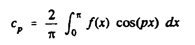
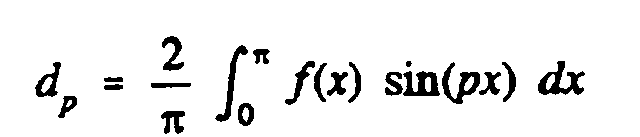
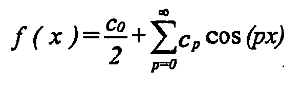
- Pursuant to the invention, this task is solved by the invention mentioned in claim 1 where one or more channels are defined by the piston rod and/or the piston valve rod in the assembled activation pin which channels are positioned in a mainly longitudinal direction in relation to the centre axis of the activation pin, of which the cross section approximately can be defined by at least one closed curve, which can be defined by two unique modular parametrisation Fourier Series expansions, one for each co-ordinate function:where
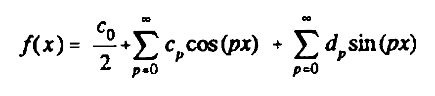
 0 ≤ x ≤2π, x ∈
 p ≥ 0, p ∈

- cp =
- cos-weighted average values of f(x),
- dp =
- sin-weighted average values of f(x),
- p =
- representing the order of trigonometrical fineness
- cp =
- weighted average values of f(x),
- p =
- representing the order of trigonometrical fineness
- cp =
- weighted average values of f(x),
- p =
- representing the order of trigonometrical fineness
- r =
- the limit of the "petals" in the circular cross section of the activation pin,
- r0 =
- the radius of the circular cross section around the axis of the activation pin,
- a =
- the scale factor for the length of the "petals ",
- rmax =
- r0 + a
- m =
- the parameter for definition of the "petal" width
- n =
- the parameter for definition of the number of "petals "
- In a first appropriate embodiment of the invention, the piston rod is equipped with two blind drillings parallel with the centre axis that reaches the activation pin at both ends of the activation pin and with a concentric valve made of an elastic material, e.g. a valve rubber used on a Dunlop-Woods valve and squeezed onto the piston rod between e.g. its upper and lower part covering the radial drilling proximal to the pressure source. The radial drilling has an azimuth angle ∝ larger than or equal to 90° to the centre axis of the piston seen in the flow direction of the air at flow from the side of the pressure source. Furthermore, the distal radial drilling has an azimuth angle β larger than or equal to 90° to the distal centre drilling of the piston, seen in the flow direction of the air at flow from the side of the pressure source. To ensure an interaction between the piston and the inner valve in a Schrader-valve, the radius r0 in the distal blind drilling is smaller than the radius r0 of the proximal part of the centre drilling. Due to evident arrangements in dimensioning the by-pass, the piston control is proximally equipped with longitudinal air ducts and/or it has a bigger diameter. Moreover, the side of the piston is chamfered. If connected to e.g. a pump with a built-in check-valve the connector needs to have an airing valve or a similar solution, providing shortest pumping time. This results in a reliable activation pin as the pin valve works independantly of the piston control fit and tolerances of the pump valves in question. A pin with a low aerodynamic drag which is comfortable for pumping purposes and a pin which is cheap to produce.
- A second appropriate embodiment is an improvement of the first embodiment, if the coupling is connected to e.g. a high-pressure pump with a built-in non-return valve. A spring force being produced by means of the combination of compressed air and the valve lever passing through the piston in an eccentric position ensures lowest possible pumping time. The effect of the eccentric valve lever is that the air pressure in the space between the non-return valve of the pump and the activation pin becomes equal to the pressure of the surroundings as the valve lever opens the above-mentioned space if a Schrader-valve is disconnected. It is thus always possible to couple a Sclaverand-valve without air escaping from the tire. Alternatively, an airing valve which is constantly shut could be established in the above-mentioned space when the connector is coupled to the valves or when the activation pin touches the core of the Schrader valve. This can take place if, for example, the airing is shaped as a narrow channel at the pressurized side of the activation pin to the distal end of it. In a special appropriate embodiment it is proposed that the eccentric valve lever is integrated in the piston valve which makes the activation pin cheap to produce. The pin works independantly of the piston control fit.
- A third appropriate embodiment comprises a simular combination as described in the second embodiment, but the difference is the pin has a central drilling. It is appropriate if the central drilling at each end expands gradually by a circular cross section and has an angle y or δ, respectively, with the center axis of the activation pin and each is larger than 0° and smaller than 20°, usually in the interval between 6° and 12°. In an appropriate embodiment, the top of the piston of the activation pin forms a valve seat for the valve (304). This results in a big opening area by a small movement of the eccentric valve lever. In a special appropriate embodiment it is suggested that the eccentric valve lever is loose in the piston and a stop device is used for its movement and that a stop device is used for the piston valve which is an integrated part hereof and is resilient in relation to it. The piston valve rod has e.g. a "flower-shapped" cross section and the piston rod e.g. a circular, resulting in air channels (321). The activation pin is very reliable and cheap to produce. The air flow in the valve connector is approximately laminar which ensures low aerodynamic drag so that it is comfortable when pumping even with (low pressure) pumps without an integrated non-return valve: the improvement above the activation pin in figure 9 (WO 96/10903) is considerable regarding reduction in pumping force and pumping time.
- A fourth embodiment is an altemativ of the third embodiment, as the piston valve is rotating at an angle in relation to the top of the piston, if activated by the eccentric valve lever. The rotation is limited with a stop device. The cross section of the piston rod can have two main forms according the specific formula: "flower-shaped" with different parameters, both resulting in an approximately laminair flow. In a specific appropriate embodiment the radius r0 is smaller than the radius of the core of Schrader, while the air is flowing through the distals of the "flower shaped" cross section. The eccentric valve lever is similar of the loose type of Figure 5D, with the diffrence that the top is rounded off. The characteristics of this model are almost in accordance with these from the third embodiment.
- In a fifth appropriate embodiment of the invention, the activation pin is designed as a piston with a piston rod that is slidable in the cylinder-shaped coupling house where the activation pin has a centre drilling with an axially slidable valve in the centre drilling that is kept closed by a spring where the centre drilling of the activation pin has e.g. a "flower-shaped" cross section (D-D, figure 8B) and the piston valve rod a circular one resulting in a reliable control and efficient air passage and the centre drilling at each end expands gradually by a circular cross section. The walls of the gradual expansions form an angle ρ or , respectively, between 0° and 20° (usually in the interval between 6° and 12°). The wall of the gradual expansion by the piston part of the centre drilling forms a valve seat for the seal face of the valve. The seal face of the valve is pressed into the correct position by a spring, e.g. an elastic band. In a special appropriate embodiment the sealing surface is a small area with an angle ψ in relation to the centre axis of approximately 90°-150° (incl.), seen in the flow direction of the air at flow from the side of the pressure source, enabling an improved sealing. In a special appropriate embodiment, the valve is equipped with at least one fin or a similar device which fits on the top of the edge of a Dunlop-Woods inner valve. It fits the top of the core of the Schrader-valve too or it fits the bridge of the Schrader-valve, without fitting the top of this core, as the activation pin does. In the last mentioned embodiment the fin is equipped with a device perpendicular to the fin. Furthermore, the centre drilling in the last-mentioned embodiment can also be designed in a way that provides a favourable flow in the area around the fin of the piston part. If e.g. combined with a pump with a built-in check-valve the space between the connector and the check-valve need to have an airing or a similar solution. The activation pin is reliable, as it works independant of the piston rod fit and the tolerances of the pump valves. It is cheap to produce and it gives a low pump force, specifically with pumps without a check-valve. It works independant of piston control fit or pump valve tolerances.
- In a sixth appropriate embodiment of the invention, the activation pin has a centre axial drilling with a valve that is axially slidable in the drilling and that is kept closed by means of a spring. The valve and the spring are made in one piece of a deformable material. The axially slidable valve and the spring are partly formed by a conic section with an apex angle (2ε) and partly by an approximate cylindrical section with a mainly circular cross section. The spring is attached to the piston part of the activation pin by means of a securing device. This is expedient if the wall of the centre drilling in the activation pin is gradually expanded and has an angle η or ν, respectively, in relation to the centre axis of the activation pin which each is larger than 0° and smaller than 20° (usually in the interval between 6° and 12°). The wall of the gradual expansion of the centre drilling thus forms a valve seat for the seal face of the valve. The valve is pulled to the tightening position by the spring. In a special appropriate embodiment of the invention, the piston part is equipped with at least one fin or a similar device which fits on top of the core of Schrader. In another appropriate embodiment of the activation pin, the slidable valve has two cones resting upon each other. This turns the air flow around the valve and in the grooves into an approximate laminar flow. The piston valve rod and the piston rod defines e.g. a cylindrical air channel, while the rest of the piston rod has a "flower-shaped" cross section. The embodiment of the flow ensures low aerodynamic drag so that it is comfortable when pumping even with low pressure pumps without an integrated non-return valve. Besides, the invention is cheap. It works independantly of piston control fit and pump valve tolrances. In a special appropriate embodiment the sealing surface of the cones is a small area with an angle ξ in relation to the centre axis of approximately 90°-150° (incl.) with the centre axis seen in the flow direction of the air at flow from the side of the pressure source, enabling an improved sealing. In the case of combining this embodiment with pumps with an built-in check-valve, the space between the connector and the check-valve needs to be equipped with airing or the like.
- Instead of air, gasses and/or liquids of any kind can activate and run through and around the embodiments of the activation pin. The invention can be used in all types of valve connectors, where at least a Schrader valve or any valve with a spring operated core can be coupled, irrespective the method of coupling or the amount of coupling holes in the connector which can be coupled to any pressure source. Any possible combination of the embodiments shown in the specification fall into the scope of the present invention. The various embodiments described above are provided by way of illustration and should not be constructed to limit the invention. Those skilled in the art will readily recognize various modifications and changes which may be made to the present invention without strictly following the exemplary embodiments and applications illustrated and described herin, and without departing from the true spirit and scope of the present invention.
- In the following, the invention is described in details by means of the preferred embodiments of which the main construction elements are shown on the drawings. The following is shown on the drawing:
- Figure 1A
- shows an illustration of a channel's curve which is defined by two unique modular parametrisation Fourier Series expansion.
- Figure 1B
- shows an illustration of the mathematical model of the "flower-shaped" cross section.
- Figure 2
- shows a first embodiment of the activation pin shown in a distal position to the pressure source in a valve connector that can be squeezed onto valves.
- Figure 2A
- shows an enlargement of the piston valve according to Figure 2. The broken line drawing shows the valve when it is open.
- Figure 2B
- shows the side drilling positioned distally in the piston rod together with a centre blind drilling of the embodiment of Figure 2.
- Figure 3A
- shows an enlargement of a further development of the second embodiment of the activation pin where the valve in the activation pin is activated by the eccentric valve lever.
- Figure 3B
- shows the activation pin according to Figure 3A where the valve in the activation pin is kept closed by air pressure.
- Figure 3C
- shows section A-A of Figure 3A.
- Figure 3D
- shows the top of the piston and valve of the activation pin from above according to Figure 3A (view X).
- Figure 4
- shows a third embodiment of the activation pin in a distal position to the presure source in a valve connector that can be squeezed onto valves.
- Figure 5A
- shows an enlargement of the activation pin according to Figure 4. The valve of the activation pin is activated by the eccentric valve lever.
- Figure 5B
- shows the activation pin according to Figure 5A where the valve is shut by air pressure.
- Figure 5C
- shows section B-B of Figure 5A (the piston is not shown).
- Figure 5D
- shows an eccentric valve lever that is freely movable in the piston of the activation pin.
- Figure 6A
- shows the fourth embodiment of an activation pin similar to Figure 5, with a rotatable piston valve which is activated by the eccentric valve lever.
- Figure 6B
- shows the activation pin according Figure 6A, where the piston valve is closed by air pressure.
- Figure 6C
- shows view Z of Figure 6A.
- Figure 6D
- shows cross section C-C of Figure 6B.
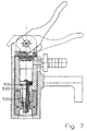
- Figure 7
- shows a fifth embodiment of the invention in a distal position to the pressure source in a valve connector that can be squeezed onto valves.
- Figure 8A
- shows an enlargement of the invention according to Figure 7 where the valve in the activation pin is activated.
- Figure 8B
- shows section D-D of figure 8A.
- Figure 8C
- shows an enlargement of the invention according to Figure 7 where the valve in the activation pin is kept closed by the spring.
- Figure 8D
- shows the embodiment according to Figure 8C, with a different sealing surface.
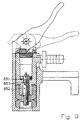
- Figure 9
- shows the sixth embodiment of the invention in a distal position to the pressure source in a valve connector that can be squeezed onto valves.
- Figure 10A
- shows an enlargement of the embodiment of Figure 9 where the valve in the activation pin is in a closed position or activated position (broken lines).
- Figure 10B
- shows the top of the activation pin according to Figure 10A with spring suspension and intake (view Y).
- Figure 10C
- shows a section after the line E-E in Figure 10A.
- Figure 10D
- shows a section after the line F-F in Figure 10A.
- Figure 11A
- shows the embodiment according to Figure 10A, with a different sealing surface.
- Figure 11B
- shows en enlargement of the sealing surface of the embodiment of Figure 11A.
-
- Figure 1A shows a cross section of e.g. a
piston rod 801 with achannel 802. Its curve is defined by two unique modular parametrisation Fourier Series expansion. - Figure 1B shows a mathematical model of the "flower-shaped" cross section that
provides a suitable approximation. The general formula for this cross section is found above.
In the model shown is:
r 0 ≈ 0.4 rmax, m = 4 and n = 6.
The change from a central drilling 303,410,533,653 to the circle round section of expansions 312,313,411,412,538,539,658 can mathematically be expressed by
r 0 → r max
under retention of the other parameters.
Figure 2 shows the first embodiment with thepiston 121 in its distal position to the pressure source in a valve connector that is squeezed onto valves. Thepiston 121 has apiston rod 122 and is equipped with a centreblind drilling 123 which branches into at least oneradial drilling 124. Both blind drillings 123,128 has e.g. a "flower-shaped" cross section, of which the radius r0 ofblind drilling 123 is larger than radius r0 ofblind drilling 128. The proximal part ofdrilling 123 and the distal part ofdrilling 128 can be provided with gradual expansions (not shown), seen from the pressure source. - Figure 2A shows the
radial drilling 124 which has an azimuth angle a to thecentral axis 125 of thepiston 121. The angle a is shown larger than 90°. Theradial drilling 124 is led to the underside of thevalve 126. Thevalve 126 is shown in its open position by means of abroken line 126a.Valve 126 is fastened by being squeezed between e.g. the upper and lower part (not shown) of the piston rod. - Figure 2B shows the
radial drilling 127 which is open at an angle β to theblind drilling 128. The angle β is shown larger than 90°. Theradial drilling 127 is led to e.g. a centreblind drilling 128 at a distal position on thepiston rod 122. - Figure 3A shows a further development of the activation pin pursuant to Figure 2 where
the axially
movable piston valve 225 is in activated position by theeccentric valve lever 226 which is integrated in thepiston valve 225 and where thepiston valve rod 227 has a sealingsurface 228 which is positioned at the end in order to ensure that thepiston valve 225 always opens up and make an air flow possible e.g. from the space between the non-return valve of a pump and the activation pin to the surroundings, when a Schrader-valve is uncoupled. Thepiston rod 223 has a sealing 229 with a sealingsurface 230. Thepiston valve 225 has a sealing 238 with sealingsurface 239 and the top of thepiston 222 has a sealingsurface 240. The radius r0 ofdrilling 248 is smaller than radius r0 ofdrilling 224. The air flows through thecentral drilling 224 which has a "flower-shaped" secton and around thepiston rod 227 which has a circular cross section resulting in air channels 234 (section A-A) which form thecentral drilling 224.Stop device 231 prevents the piston valve from being pulled out of the activation pin as it strokes against thepiston rod 223.Radial drilling 247 distally.Centre axis 237 of the activation pin. The piston valve can have a gradual expansion (not shown) proximal the pressure source. - Figure 3B shows the activation pin according to Figure 3A where the
piston valve 225 is kept shut by air pressure. The valve function is fulfilled by the sealing 236 in full accordance with Figure 2. Thestop device 231 has astop surface 232 and thepiston rod 223 has astop surface 233. - Figure 3C shows section A-A of the
piston valve 223 which has a "flower-shaped" section and thepiston valve rod 227 which has a circular cross section resulting inair channel 234 in order to enable a suitable flow through the section with a reliable guidance of thepiston valve rod 227. - Figure 3D shows view X of the top of the activation pin where the
piston valve rod 227 is hanged up inshackle 235. Besides, the figure also shows theeccentric valve lever 226 which is integrated into thepiston valve 225 and which is a section of a cylinder surface. In an appropriate embodiment not shown the valve lever is made by means of at least two legs that can be arranged rotationally symmetric around thecentral axis 237 of the activation pin. The embodiments described in Figure 3D are, of course, applicable in connection with the other embodiments. - Figure 4 shows the third embodiment of the activation pin with
piston 301 in its distal position to the pressure source in a coupling house of a valve connector that can be squeezed onto tires valves. Thepiston 301 has apiston rod 302 and has acentral drilling 303. The activation pin has apiston valve 304 and aneccentric valve lever 305.Centre axis 337. - Figure 5A shows an enlargement of the activation pin of Figure 4 where the axially
movable piston valve 304 is in activated position by theeccentric valve lever 305 and where it has a sealing 306 with a sealingsurface 307. Thepiston 301 has a sealingsurface 309. The air flows through the proximallygradual expansion 310 of thecentral drilling 303 which e.g has a "flower-shaped" section to the distallygradual expansion 311. The wall 312,313 forms an angle γ or δ, respectively, with thecentral axis 337 of thecentral drilling 303 and these angles are each larger than 0° and smaller than 20° and are usually in the interval between 6° and 12°. Both expansions 310,311 have an approximately circular section. Together the "flower-shaped" cross-section of thepiston valve rod 322air channels 321 are defined of which e.g. four can be used in order to get an approximately laminair air flow. Thestop 315 prevents thepiston valve 304 to be pulled out of the activation pin in case that the coupling is connected to a piston pump without a non-return valve. Thestop 315 is resiliently mounted by means of thebar 316 in thebottom 317 of thepiston valve rod 322. The activation pin has distally at least one fin or ashackle 318 which is optimally shaped in terms of air flow. - Figure 5B shows the activation pin according to Figure 5A where the
piston valve 304 is kept shut by air pressure. Thestop device 315 hasstop surface 319 and thestop surface 320 is a part of thepiston rod 302. - Figure 5C shows a section B-B with the
air channel 311 which has a suitable flow through the section area. Moreover, thestop device 315 and thefin 318 are shown. - Figure 5D shows the activation pin in an activated position with an
eccentric valve lever 350 which is freely movable in thepiston 301 of the activation pin and on which thepiston valve 353 presses at the top 351. Thestop device 352 ensures that the valve lever does not fall through thepiston 301. In an appropriate embodiment not shown the valve lever has at least two legs which can be positioned rotationally symmetrical around thecenter axis 337 of the activation pin. The valve lever can also be designed as thevalve lever 226 shown in Figure 3A. Embodiments described in Figure 5D are, of course, also applicable in connection with the other embodiments. - Figure 6A shows a fourth embodiment of the activation pin, which is similar to the third
embodiment, in a position where the
piston valve 401 is opened by the activatedeccentric valve lever 402. Thepiston valve 401 is rotatable over an angle from thecentral axis 403 of the activation pin. It rotates around anaxis 404 which is perpendicular to thecentral axis 403. The rotation of thepiston valve 401 is limited by thestop device 405. Thepiston valve 401 has a sealing 414 with a sealingsurface 406, while the piston 407 has a sealingsurface 408. For the rest is the activation pin similar to Figure 5A, except for thepiston rod 420 and theeccentric valve lever 402 to Figure 5D which has a roundedtop 421. - Figure 6B shows the activation pin similar to fig. 6A with the
piston valve 401 shut. Thepiston rod 409 has different parameters for the "flower-shaped" cross section of thecentral drilling 418. Also here are two gradual expansions 410,412 and walls 411,412, respectively, with characteristics according to those of Figure 5A: angles µ and κ in relation to thecentre axis 403. The contact area 413 (see also fig. 6B) of the activation pin with a Schrader-valve has a cone shape. No bridge is necessary, as r0 is smaller than the diameter of the core of a Schrader-valve. - Figure 6C shows view Z of fig. 6A with
fin 415 andopening 416. - Figure 6D shows cross section C-C of Figure 6B with the "flower-shaped" cross section
of the
piston rod 409 definingair channel 417.Contact area 413 with the core of Schrader. - Figure 7 shows a fifth embodiment with the
piston 531 in its distal position to the pressure source in the coupling house of a valve connector that can be squeezed onto valves. Thepiston 531 has apiston rod 532 and is equipped with acentre drilling 533. - Figure 8A shows the activation pin in activated position where an axially
slidable valve 534 has aseal face 535. The air flows through a proximal (to the pressure source)gradual expansion 536 of thecentre drilling 533 and through the latter to the distalgradual expansion 537. The wall 538,539 forms an angle ρ or ϕ, respectively, to thewall 540 of thecentre drilling 533. These are larger than 0° and smaller than 20° (usually in the interval between 6° and 12°). Both expansions 536,537 have an approximately circular cross section distally from the connection to thecentre drilling 533.Centre axis 543.Piston valve rod 544. - Figure 8B shows the section D-D from figure 8A where the
air channel 533 is defined by a "flower-shaped" cross section of thepiston rod 532 and a circular cross section of thevalve rod 544. Furthermore, afin 542 is shown. - Figure 8C shows the activation pin with a closed valve. The
spring 541 secured in thepiston 531 is an elastic band which presses the axiallyslidable valve 534 down so that theseal face 535 of the valve is pressed against the wall 538 of theexpansion 536. Theseal face 535 can have a similar sealing (not showed) with the wall 538 as showed in Figure 11A, 11B. - Figure 8D shows an improved sealing surface arrangement. Sealing 550 with
surface 551 andpiston rod 553 with sealingsurface 552. Angle ψ between 90°-150° (incl.). - Figure 9 shows a sixth embodiment with the
piston 651 in its distal (to the pressure source) position in a coupling house of a valve connector that can be squeezed onto valves. Thepiston 651 has apiston rod 652 and is equipped with acentre drilling 653. - Figure 10A shows the activation pin in its closed position and its activated position
(broken lines) where the axially
slidable valve 654 has aseal face 655. The air flows through theexpansion 656 of thecentre drilling 653 and through the latter to the distalgradual expansion 657 and the distal part of the piston rod with a "flower-shaped" cross section. The wall 658,659 forms an angle η or ν, respectively, to thewall 660 of thecentre drilling 653. These angles are each larger than 0° and smaller than 20° (usually in the interval between 6° and 12°). Both expansions 656,657 have an approximately circular cross section. Thevalve 654 has aspring part 661 secured in abrace 662. Distally, the activation pin has at least one fin orbrace 663. Furthermore, acone 664 is shown. - Figure 10B shows the top (view Y) of the activation pin shown in figure 10A with the
three
expansions 656 and braces 662. The braces serve as a securing device for the valve spring and theexpansions 656 ensure a suitable flow cross section. - Figure 10C shows that the section E-E in figure 10A resulting in a
cylindrical air channel 653. A suitable flow cross section is also ensured here. - Figure 10D shows the section F-F in figure 10A. Internally, this section of the
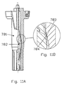
piston rod 652 is "flower-shaped" to ensure a suitable flow cross section. Furthermore, a fin designed as abrace 663 is shown. - Figure 11A shows an activation pin similar to the one of Figure 10, with the difference
that the sealing
surface 704 of thecone 702 and thecorresponding surface 703 for thepiston rod 701 have an angle ξ equal or larger than 90° and less than approximately 150° with thecentre axis 665 seen in the air flow direction at flow from the pressure source. -
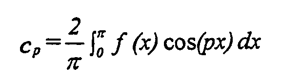
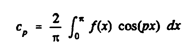
- Activating pin for a valve connector, which activating pin is designed as a piston (121,222,301,407,531,651) with a piston rod (122,223,302,409,420,532,652,701), moving in the coupling house of the valve connector where the activating pin has a central drilling (123,128,224,248,303,418,533,653) and a piston valve (126,225,304,353,401,534,654,702) kept closed by a spring force which is where one or more channels (123,128,224,234,303,321, 417,418,533,653,657) are defined by the piston rod (122,223,302,409,420,532,652,701) and/or the piston valve rod (227,322,544,661) in the assembled activating pin which channels (123,128,224,234,303,321,417,418,533,653,657) are positioned in a mainly longitudinal direction in relation to the centre axis (125,237,337,403,543,665) of the activating pin, of which the cross section approximately can be defined by at least one closed curve, which can be defined by two unique modular parametrisation Fourier Series expansions, one for each co-ordinate function:where

 0 ≤ x ≤ 2π, x ∈
 p ≥ 0, p ∈

- cp =
- cos-weighted average values off(x),
- dp =
- sin-weighted average values off(x),
- p =
- representing the order of trigonometrical fineness
- cp =
- weighted average values off(x),
- p =
- representing the order of trigonometrical fineness
- cp =
- weighted average values off(x),
- p =
- representing the order of trigonometrical fineness
- r =
- the limit of the ''petals'' in the circular cross section of the activating pin,
- r0 =
- the radius of the circular cross section around the axis of the activating pin,
- a =
- the scale factor for the length of the ''petals'',
- rmax =
- r0 + a
- m =
- the parameter for definition of the "petal" width
- n =
- the parameterfor definition of the number of ''petals''
- ϕ =
- the angle which bounds the curve.



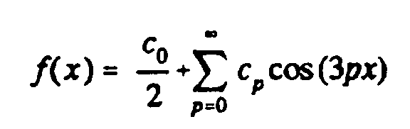


r 0 ≥ 0,
a ≥ 0,
m ≥ 0, m ∈ R,
n ≥ 0, n ∈ R,
0 ≤ ϕ ≤ 2π,
and where


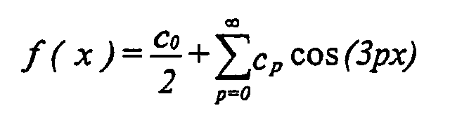
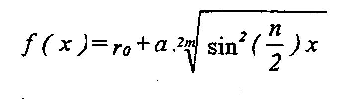
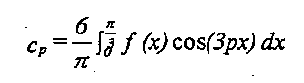


r0 ≥ 0,
a ≥ 0,
m ≥ 0, m ∈ R,
n ≥ 0, n ∈ R,
0 ≤ ϕ ≤ 2Π, and where
The centre drilling (123,128) can be designed as two blind drillings, parallel with the centre axis (125) which at both ends of the activating pin reach into the activating pin where it is connected by means of suitable radial drillings (124,127), that the proximal radial drilling (124) proximal to the pressure source has an azimuth angle (α) larger than or equal to 90° to the centre axis (125) of the piston (121) seen in the air flow direction at flow from the pressure source, and that the piston rod (122) is equipped with a concentric valve (126) of elastic material which is squeezed onto the piston rod (122) covering the side drilling (124).
The distal radial drilling (127) can have an azimuth angle (β) larger than or equal to 90° to the centre blind drilling (128) of the piston rod (122) seen in the flow direction of the air at flow from the pressure source. The radius ro of the distal centre blind drilling (128). can be smaller than ro of the proximal part of the centre drilling (123).
The spring force can be procured by means of the combination of pressurized air and the valve lever (226,305,402), which passes through the piston (222,301,407) eccentrically.
The piston valve (225,304) can be axially movable.
The piston valve (225,304) can be equipped with a stop device (231,315).
The piston rod (223) can be equipped with at least one radial drilling (244,247) and with a concentric valve (236) of elastic material which is squeezed onto the piston rod (223) and which is covering the radial drilling (244).
The radial drilling (244) can have an azimuth angle (α) larger than or equal to 90° with the center axis (237) of the piston (223) seen in the flow direction of the air at flow from the pressure source.
The radial drilling (247) is placed distally on the piston rod (223) which also has a central drilling (248) wherein the radial drilling (247) can have an azimuth angle (β) which is larger than or equal to 90° with the centre axis (237) of the piston rod (223) centre drilling (248) and where radial drilling (247) ends up in the centre drilling (248).
The piston valve rod (227) can be hung up by means of a securing device (235).
The central drilling (303,418) at each end can be gradually expanding to an approximately circular cross section (310,311,410,419).
The expanding wall (312,313,411,412) can have an angle (ϒ,µ) or (δ,κ), respectively, in relation to the central axis (337,403) of the activating pin which angles each are larger than 0° and smaller than 20°.
The angle (ϒ,µ) or (δ,κ), respectively, can be in the interval between 6° and 12°.
The top (240,309,408) of the piston (222,301,407) of the activating pin at the central drilling (224,303) can procure a valve seat for the sealing means (238,306,414) of the piston valve (225,304,401).
The bottom (228) of the piston valve rod (227) can procure a valve seat for the sealing means (229) in the bottom of the central drilling (224).
The valve lever (350) can be axially freely movable through the top surface (351) where the mobility is limited by the piston valve (353) and by the piston (301) through the stop device (352). he valve lever (226,305) can be equipped with at least two legs.
The legs of the valve lever (226,305) can be organized rotationally symmetric around the central axis (237,337).
The valve lever (226) can be an integrated part of the piston valve (225) being a part of a cylinder surface.
The piston rod (302,420) can be equipped with at least one fin (318).
The piston valve (401) can rotate around an axis (404) which is perpendicular to the centre axis (403).
The rotation of the piston valve (401) can be limited by a stop device (405).
The valve lever (402) can be axially freely movable where the mobility is limited by the piston valve (401) by through the
The radius ro of the central drilling (418) can be smaller than the diameter of the core of a Schrader-valve contact area (413).
The centre drilling (533) can go through the entire piston rod (532).
The piston valve rod (544,553) can be controlled by the piston and that the valve spring device (541) consists of an elastic band.
The wall (538,539) of the centre drilling at each end of the piston rod (532,553) can be gradually expanding to an approximately circular cross section at either end.
The wall (538,539) of the gradual expansion (536,537) can form an angle ρ or ϕ, respectively, with the centre axis (543) which is larger than 0° and smaller than 20°.
The angle ρ or ϕ , respectively, can be in the interval between 6° and 12°. The wall (538) of the gradual expansion (536) by the piston part of the centre drilling (533) can form a valve seat for the seal face (535) of the piston valve (534).
The piston valve (534) can be equipped with at least one fin (542). The sealing surface (551) of the sealing (550) can form an angle Ψ equal or larger than 90° and equal or less than 150° in relation to the centre axis (543) of the activating pin seen in the flow direction of the air at flow from the side of the pressure source.
The piston valve (654) and the spring (661) can be made in one piece of a deformable material with a suitable modulus of elasticity.
The slidable valve (654) and the spring (661) can consist partly of a conic section with an apex angle (2ε) and partly of an approximate cylindrical section with a mainly circular cross section and that the spring (661) is secured in the piston part (651) of the activating pin by means of a securing device (662).
The wall (658,659) of the centre drilling (653) in the activating pin can be gradually expanding to an angle η or ν , respectively, to the centre axis (665) of the activating pin.
The angle η or ν, respectively, to the centre axis (665) of the activating pin can be each larger than 0° and smaller than 20°.
The angle η or ν, respectively, is in the interval between 6° and 12°.
The wall (659) of the gradual expansion (657) of the centre drilling (653) can form a valve seat for the seal face (655) of the valve (654).
The conic section of the slidable valve (654) can consist of two cone parts resting upon each other.
The fin (542) can be equipped with a device perpendicular to the fin.
The sealing surface (704) of cone (702) can form an angle ξ equal or larger than 90° and less than approximately 150° in relation to the centre axis (665) of the activating pin seen in the flow direction of the air at flow from the pressure source.
Claims (12)
- An activating pin for a valve connector for connecting to spring-force operated valves, the connector comprisingwhereina housing to be connected to a pressure source,within the housinga coupling hole having a central axis and an inner diameter approximately corresponding to the outer diameter of the inflation valve to which the valve connector is to be connected, anda cylinder and means for conducting gaseous media between the cylinder and the pressure source, and where the activating pinis arranged to engage a central spring-force operated core pin of the inflation valve,is arranged to be situated within the housing in continuation of the coupling hole coaxially with the central axis thereof, andcomprises a piston part with a piston, which piston is to be positioned in the cylinder movable between a first piston position and a second piston position,the activating pin comprising a channel,said piston part comprises a first end and a second end, wherein the piston is located at said first end and said channel has an opening at said first end,a valve part being movable in the channel, drivable by difference in forces acting on surfaces of the valve part, between a first valve position and a second valve position, wherein said first valve position leaves said opening open, and said second valve position closes said opening, andthe top of the piston part forming a valve seat for a seal face of the valve the valve means.
- An activating pin according to claim 1, in a valve connecter for connecting to inflation valves, wherein the channel comprising a part being partly expanding in the direction towards the valve part, the angle of the expanding wall being 0-20°, such as 6-12°, in relation to a central axis of the activating pin.
- An activating pin according to claim 1 or 2, in a valve connecter for connecting to inflation valves, wherein it comprises means for driving said valve part into said first valve position when the piston is in the first piston position.
- An activating pin according to claim 1, in a valve connecter for connecting to inflation valves, wherein said valve part is arrangend to move in respect of said piston part in the longitudinal direction of said piston part.
- An activating pin according to claim 1, in a valve connecter for connecting to inflation valves, wherein said valve part is arrangend to rotate around a rotational axis mounted at said first end perpendicularly to the longitudinal axis of said piston part.
- An activating pin according to claim 4, in a valve connecter for connecting to inflation valves, wherein it comprises stopping means to limit the movement of said valve part in the longitudinal direction of said piston part.
- An activating pin according to claim 5, in a valve connecter for connecting to inflation valves, wherein it comprises stopping means to limit the rotation of said valve part in the first valve position.
- An activating pin according to claim 4, in a valve connecter for connecting to inflation valves, whereinwherein said first valve position corresponds to said valve part being moved in the longitudinal direction of said piston part to a position where the free end of said valve rod leaves open the transition point between said first channel portion and said second channel portion, and said second valve position corresponds to said valve part being moved in the longitudinal direction of said piston part to a position where the free end of said valve rod closes the transition point between said first channel portion and said second channel portion.said piston part comprises a first end and a second end, wherein the piston is located at said first end,said channel comprises a first channel portion and a second channel portion, both in the longitudinal direction of said piston part and connected to each other at a transition point, andsaid valve part comprises a valve rod arrangend to move within said first channel portion and having a free end;
- An activating pin according to claim 8, in a valve connecter for connecting to inflation valves, wherein at least one end of said first channel portion and said second channel portion has a larger cross section area at its other end than at its next end to said transition point.
- An activating pin according to claim 4, in a valve connecter for connecting to inflation valves, wherein said piston part comprises a first end and a second end, wherein the piston is located at said first end,wherein said first valve position corresponds to said valve part being moved in the longitudinal direction of said piston part to a position where said valve sealing leaves open the circular opening of said drilling at said first end, and said second valve position corresponds to said valve part being moved in the longitudinal direction of said piston part to a position where said valve part closes the circular opening of said drilling at said first end.said channel comprises a drilling extending from said first end to said second end, the opening of said drilling at said first end being circular, andsaid valve part comprisesa valve rod with a channel positioned in the longitudinal direction of said valve part, said valve rod arrangend to move within said drilling, anda cylindrical valve sealing at one end of said valve rod, the axis of said cylindrical valve sealing being in the longitudinal direction of said piston part, said drilling and said valve rod, and the outer diameter of said valve sealing being larger than the diameter of the circular opening of said drilling at said first end;
- An activating pin according to claim 3, in a valve connecter for connecting to inflation valves, wherein said means is an integrated part of the valve part.
- The use of an activating pin according to claim 1. in a valve connector for connecting to inflation valves.
Applications Claiming Priority (9)
| Application Number | Priority Date | Filing Date | Title |
|---|---|---|---|
| DK16896 | 1996-05-14 | ||
| DK9600168U DK9600168U3 (en) | 1996-05-14 | 1996-05-14 | valve coupling |
| DK9600180U DK9600180U3 (en) | 1996-05-14 | 1996-05-24 | valve coupling |
| DK18096 | 1996-05-24 | ||
| DK9600227U DK9600227U3 (en) | 1996-05-24 | 1996-06-28 | valve coupling |
| DK22796 | 1996-06-28 | ||
| DK9700048U DK9700048U3 (en) | 1996-05-14 | 1997-01-31 | actuating pin for valve coupling |
| DK4897 | 1997-01-31 | ||
| EP19970921647 EP0906529B1 (en) | 1996-05-14 | 1997-05-14 | Activation pin |
Related Parent Applications (1)
| Application Number | Title | Priority Date | Filing Date |
|---|---|---|---|
| EP19970921647 Division EP0906529B1 (en) | 1996-05-14 | 1997-05-14 | Activation pin |
Publications (2)
| Publication Number | Publication Date |
|---|---|
| EP1437540A2 true EP1437540A2 (en) | 2004-07-14 |
| EP1437540A3 EP1437540A3 (en) | 2004-07-28 |
Family
ID=27439774
Family Applications (2)
| Application Number | Title | Priority Date | Filing Date |
|---|---|---|---|
| EP20040003470 Withdrawn EP1437540A3 (en) | 1996-05-14 | 1997-05-14 | Activation pin |
| EP19970921647 Expired - Lifetime EP0906529B1 (en) | 1996-05-14 | 1997-05-14 | Activation pin |
Family Applications After (1)
| Application Number | Title | Priority Date | Filing Date |
|---|---|---|---|
| EP19970921647 Expired - Lifetime EP0906529B1 (en) | 1996-05-14 | 1997-05-14 | Activation pin |
Country Status (27)
| Country | Link |
|---|---|
| US (1) | US6378547B1 (en) |
| EP (2) | EP1437540A3 (en) |
| JP (1) | JP2000514527A (en) |
| KR (2) | KR20000010997A (en) |
| CN (2) | CN100353104C (en) |
| AP (1) | AP9801413A0 (en) |
| AT (1) | ATE259954T1 (en) |
| AU (2) | AU739666B2 (en) |
| BR (1) | BR9709242A (en) |
| CA (1) | CA2254964A1 (en) |
| CY (1) | CY2467B1 (en) |
| DE (1) | DE69727678T2 (en) |
| DK (2) | DK9700048U3 (en) |
| EA (1) | EA000511B1 (en) |
| ES (1) | ES2218678T3 (en) |
| HU (1) | HUP9904704A3 (en) |
| NO (2) | NO985269L (en) |
| NZ (2) | NZ333327A (en) |
| OA (1) | OA10923A (en) |
| PL (1) | PL184214B1 (en) |
| PT (1) | PT906529E (en) |
| RO (1) | RO119137B1 (en) |
| SI (1) | SI0906529T1 (en) |
| SK (1) | SK155998A3 (en) |
| TW (2) | TW363924B (en) |
| UA (1) | UA73068C2 (en) |
| WO (1) | WO1997043570A1 (en) |
Families Citing this family (14)
| Publication number | Priority date | Publication date | Assignee | Title |
|---|---|---|---|---|
| HUP9900497A3 (en) | 1995-02-03 | 2001-03-28 | Nvb International | Valve connector |
| TW363924B (en) | 1996-05-14 | 1999-07-11 | Nvb Int | Activation pin for valve connector providing a reliable activation pin which is inexpensive, has low air-power resistance, and is therefore suitable for use as pump |
| US6648005B2 (en) | 1998-11-13 | 2003-11-18 | Nvb International | Activation pin |
| WO2002077457A1 (en) | 2001-03-27 | 2002-10-03 | Nvb Composites International A/S | A combination of a chamber and a piston, a pump, a motor, a shock absorber and a transducer incorporating the combination |
| TW201207237A (en) * | 2010-08-03 | 2012-02-16 | Shu-Mu Wu | Air pump head |
| TW201235565A (en) | 2011-02-25 | 2012-09-01 | Nvb Composites Internat Uk Ltd | Piston-chamber combination vanderblom motor |
| PH12014500264A1 (en) | 2011-07-01 | 2014-03-17 | Nvb Composites Int Uk Ltd | Piston-chamber combination-vanderblom motor |
| US9328834B2 (en) * | 2014-04-30 | 2016-05-03 | Beto Engineering & Marketing Co., Ltd. | Air valve connecting device |
| CN104595537B (en) * | 2014-12-24 | 2017-01-18 | 宁波五马实业有限公司 | Tire valve connector capable of being rapidly installed |
| TWI632317B (en) * | 2017-09-12 | 2018-08-11 | 雙餘實業股份有限公司 | Inflatable joint |
| WO2019193744A1 (en) * | 2018-04-06 | 2019-10-10 | 太平洋工業株式会社 | Tire valve |
| TWI665401B (en) * | 2018-08-21 | 2019-07-11 | 許龍國 | Gas nozzle connector with automatic air-stop structure |
| EP4155590A1 (en) * | 2019-03-26 | 2023-03-29 | Pacific Industrial Co., Ltd. | Valve |
| US11168678B2 (en) * | 2020-03-05 | 2021-11-09 | Scott Wu | Inflation pump |
Citations (1)
| Publication number | Priority date | Publication date | Assignee | Title |
|---|---|---|---|---|
| WO1996010903A2 (en) | 1995-02-03 | 1996-04-18 | Nvb International | Valve connector |
Family Cites Families (40)
| Publication number | Priority date | Publication date | Assignee | Title |
|---|---|---|---|---|
| US1492838A (en) | 1917-11-26 | 1924-05-06 | Lloyd W Dilweg | Device for transmitting compressed air to automob ile tires |
| GB231992A (en) | 1924-02-29 | 1925-04-16 | Dunlop Rubber Co | An improved connection for fitment to valves of pneumatic tyres |
| US1850111A (en) | 1928-09-10 | 1932-03-22 | Paul C Swole | Combined air gauge and self closing outlet fitting |
| US2025067A (en) | 1934-12-17 | 1935-12-24 | Thomas S Miller | Tank filling device |
| US2257498A (en) | 1939-10-10 | 1941-09-30 | Clarence K Hansen | Tire inflation apparatus |
| US2489397A (en) * | 1944-05-05 | 1949-11-29 | Brummer Henry | Tire valve operating device |
| US2716998A (en) | 1949-03-02 | 1955-09-06 | Joseph J Knasko | Combined tire inflating chuck, deflator and blow gun |
| US2685906A (en) | 1952-01-19 | 1954-08-10 | Scovill Manufacturing Co | Running inflation and deflation system |
| GB872246A (en) | 1956-08-03 | 1961-07-05 | Walters & Dobson Ltd | Improvements in or relating to tyre valve connectors |
| US2976906A (en) | 1958-09-10 | 1961-03-28 | Wunibald I E Kamm | Tire pressure control device |
| GB977139A (en) | 1962-10-15 | 1964-12-02 | Walters & Dobson Ltd | Improvements in or relating to tyre valve connectors |
| US3249144A (en) | 1964-09-23 | 1966-05-03 | Berg Mfg & Sales Co | Tire pressure system and valve |
| FR2180164A5 (en) | 1972-04-11 | 1973-11-23 | Poutrait Morin | |
| US3911988A (en) * | 1974-02-21 | 1975-10-14 | Eaton Corp | Pressurization control device |
| DE2544555A1 (en) * | 1975-10-04 | 1977-04-07 | Magirus Deutz Ag | Pressure control valve for tyre - with low friction sprung control piston operating on non return tyre valve |
| IT1056460B (en) * | 1976-02-04 | 1982-01-30 | Dante B | VALVE BODY FOR TIRE VALVES |
| US4088147A (en) | 1976-07-09 | 1978-05-09 | Control Devices, Incorported | Air chuck |
| GB1599304A (en) | 1977-09-23 | 1981-09-30 | Scovill Inc | Inflation valve connectors |
| US4165760A (en) | 1977-10-17 | 1979-08-28 | Guenther Manfred H | Air chuck |
| US4489855A (en) | 1982-08-27 | 1984-12-25 | Code Manufacturing, Inc. | Instant tire inflator |
| JPS60500333A (en) | 1983-01-27 | 1985-03-14 | プレシジョン、ヴアルヴ、コ−ポレ−ション | tire valve fittings |
| FR2552851B1 (en) | 1983-09-30 | 1986-08-14 | Poutrait Morin | NOZZLES FOR FIXING AT THE END OF A FLEXIBLE DUCT, TO CONSTITUTE A CONNECTION FOR USE ON A PORTABLE PUMP FOR INFLATING TIRES, AND CONNECTION COMPRISING SUCH A NOZZLE |
| DE8602739U1 (en) * | 1986-02-03 | 1987-10-01 | Alligator Ventilfabrik GmbH, 7928 Giengen | Valve for pneumatic tires |
| US4662412A (en) | 1986-05-13 | 1987-05-05 | Peter Bergmann | Inflating device for use single-handed |
| US4712812A (en) | 1986-09-02 | 1987-12-15 | Weir Iii Joseph W | Universal fittings |
| DE3729327A1 (en) * | 1987-09-02 | 1989-03-16 | Bosch Gmbh Robert | Tyre pressure control valve III |
| DE3819771A1 (en) | 1987-12-18 | 1989-07-06 | Karl Scheffer Klute Gmbh & Co | HAND AIR PUMP FOR TWO-WHEEL TIRES |
| US4901747A (en) * | 1988-06-29 | 1990-02-20 | David Moliver | Tire inflation valve with pressure indicator |
| US4932451A (en) | 1989-01-26 | 1990-06-12 | General Motors Corporation | Vehicle wheel end assembly with air passage |
| US4938272A (en) | 1989-01-26 | 1990-07-03 | General Motors Corporation | Valve actuator for tire pressure management |
| FR2653523B3 (en) | 1989-10-19 | 1991-10-04 | Hernandez Manuel | ADAPTATION CONNECTION OF A COMPRESSED GAS CAN TO A TIRE INFLATION VALVE. |
| US5012954A (en) | 1990-02-08 | 1991-05-07 | Will Conrad A | Tire inflation system |
| DE4120188C1 (en) | 1991-06-19 | 1992-09-17 | Cramer Gmbh & Co Kg, 5750 Menden, De | |
| US5094263A (en) * | 1991-08-02 | 1992-03-10 | General Motors Corporation | Tire pressure management actuator with bypass leakage prevention |
| US5778923A (en) * | 1995-10-25 | 1998-07-14 | Marston; Philip William | Anti-seepage self-gauging inflation valve system |
| DE19601952A1 (en) | 1996-01-09 | 1997-07-10 | Gruener Uko Picasso | Refillable container for compressed air for inflating air-beds, tyres, e.t.c. |
| TW390942B (en) * | 1996-04-22 | 2000-05-21 | Schwinn Cycling & Fitness Inc | Combination pump head |
| TW363924B (en) | 1996-05-14 | 1999-07-11 | Nvb Int | Activation pin for valve connector providing a reliable activation pin which is inexpensive, has low air-power resistance, and is therefore suitable for use as pump |
| US5785076A (en) * | 1996-05-20 | 1998-07-28 | You; Bae-Jou | Inflating assembly for tire |
| US5819781A (en) * | 1997-07-28 | 1998-10-13 | Wu; Scott | Pumping device with a pivotal lever for various valves |
-
1996
- 1996-07-19 TW TW085108785A patent/TW363924B/en active
-
1997
- 1997-01-31 DK DK9700048U patent/DK9700048U3/en not_active IP Right Cessation
- 1997-05-14 SI SI9730644T patent/SI0906529T1/en unknown
- 1997-05-14 RO RO98-01576A patent/RO119137B1/en unknown
- 1997-05-14 AU AU27648/97A patent/AU739666B2/en not_active Ceased
- 1997-05-14 EA EA199801014A patent/EA000511B1/en not_active IP Right Cessation
- 1997-05-14 PL PL97329876A patent/PL184214B1/en not_active IP Right Cessation
- 1997-05-14 KR KR1019980709146A patent/KR20000010997A/en not_active Abandoned
- 1997-05-14 DE DE1997627678 patent/DE69727678T2/en not_active Expired - Fee Related
- 1997-05-14 JP JP54040997A patent/JP2000514527A/en not_active Ceased
- 1997-05-14 UA UA98126591A patent/UA73068C2/en unknown
- 1997-05-14 PT PT97921647T patent/PT906529E/en unknown
- 1997-05-14 ES ES97921647T patent/ES2218678T3/en not_active Expired - Lifetime
- 1997-05-14 HU HU9904704A patent/HUP9904704A3/en unknown
- 1997-05-14 CN CNB031465013A patent/CN100353104C/en not_active Expired - Fee Related
- 1997-05-14 SK SK1559-98A patent/SK155998A3/en unknown
- 1997-05-14 AT AT97921647T patent/ATE259954T1/en not_active IP Right Cessation
- 1997-05-14 NZ NZ33332797A patent/NZ333327A/en not_active IP Right Cessation
- 1997-05-14 NZ NZ505701A patent/NZ505701A/en not_active IP Right Cessation
- 1997-05-14 KR KR1020027006153A patent/KR100613121B1/en not_active Expired - Fee Related
- 1997-05-14 DK DK97921647T patent/DK0906529T3/en active
- 1997-05-14 CA CA 2254964 patent/CA2254964A1/en not_active Abandoned
- 1997-05-14 EP EP20040003470 patent/EP1437540A3/en not_active Withdrawn
- 1997-05-14 CN CN97194692A patent/CN1119542C/en not_active Expired - Fee Related
- 1997-05-14 US US09/180,689 patent/US6378547B1/en not_active Expired - Fee Related
- 1997-05-14 EP EP19970921647 patent/EP0906529B1/en not_active Expired - Lifetime
- 1997-05-14 WO PCT/DK1997/000223 patent/WO1997043570A1/en not_active Ceased
- 1997-05-14 AP APAP/P/1998/001413A patent/AP9801413A0/en unknown
- 1997-05-14 BR BR9709242A patent/BR9709242A/en not_active IP Right Cessation
-
1998
- 1998-04-10 TW TW085108785A patent/TW487654B/en active
- 1998-11-11 NO NO19985269A patent/NO985269L/en not_active Application Discontinuation
- 1998-11-13 OA OA9800221A patent/OA10923A/en unknown
-
2004
- 2004-05-19 CY CY0400058A patent/CY2467B1/en unknown
- 2004-12-09 NO NO20045378A patent/NO20045378L/en not_active Application Discontinuation
-
2005
- 2005-05-19 AU AU2005202130A patent/AU2005202130A1/en not_active Abandoned
Patent Citations (1)
| Publication number | Priority date | Publication date | Assignee | Title |
|---|---|---|---|---|
| WO1996010903A2 (en) | 1995-02-03 | 1996-04-18 | Nvb International | Valve connector |
Also Published As
Similar Documents
| Publication | Publication Date | Title |
|---|---|---|
| EP1437540A2 (en) | Activation pin | |
| JP5749928B2 (en) | Self-expanding tire assembly | |
| US6314985B1 (en) | Valve connector | |
| CN107461506B (en) | Valve plug with curved recess | |
| US6220273B1 (en) | Pumping device with an internal pivotal tube for various valves | |
| US6648005B2 (en) | Activation pin | |
| EP2810798B1 (en) | Distributed cavity air pumping assembly and method for a tire | |
| JP6831707B2 (en) | Pneumatic maintenance tires and methods with valve stems | |
| US5839764A (en) | Air line connector | |
| AU2002308385B2 (en) | A combination of a chamber and a piston, a pump, a motor, a shock absorber and a transducer incorporating the combination | |
| HK1069867A (en) | Activation pin | |
| JP2015034005A (en) | Valve assembly for air maintenance tire | |
| US20160061340A1 (en) | Pneumatic valve and air mattress assembly having pneumatic valve | |
| AU1192702A (en) | Activating pin | |
| AU2008201059A1 (en) | Activating pin | |
| EP3702106B1 (en) | Gaiter fitting device | |
| AU4534496A (en) | Valve connector |
Legal Events
| Date | Code | Title | Description |
|---|---|---|---|
| PUAI | Public reference made under article 153(3) epc to a published international application that has entered the european phase |
Free format text: ORIGINAL CODE: 0009012 |
|
| PUAL | Search report despatched |
Free format text: ORIGINAL CODE: 0009013 |
|
| AC | Divisional application: reference to earlier application |
Ref document number: 0906529 Country of ref document: EP Kind code of ref document: P |
|
| AK | Designated contracting states |
Kind code of ref document: A2 Designated state(s): AT BE CH DE DK ES FI FR GB GR IE IT LI LU MC NL PT SE |
|
| AX | Request for extension of the european patent |
Extension state: AL LT LV |
|
| AK | Designated contracting states |
Kind code of ref document: A3 Designated state(s): AT BE CH DE DK ES FI FR GB GR IE IT LI LU MC NL PT SE |
|
| AX | Request for extension of the european patent |
Extension state: AL LT LV |
|
| RIN1 | Information on inventor provided before grant (corrected) |
Inventor name: VAN DER BLOM, NICOLAAS |
|
| 17P | Request for examination filed |
Effective date: 20050128 |
|
| AKX | Designation fees paid |
Designated state(s): AT BE CH DE DK ES FI FR GB GR IE IT LI LU MC NL PT SE |
|
| REG | Reference to a national code |
Ref country code: HK Ref legal event code: DE Ref document number: 1069867 Country of ref document: HK |
|
| 17Q | First examination report despatched |
Effective date: 20050517 |
|
| 17Q | First examination report despatched |
Effective date: 20050517 |
|
| RAP1 | Party data changed (applicant data changed or rights of an application transferred) |
Owner name: NVB INTERNATIONAL A/S |
|
| REG | Reference to a national code |
Ref country code: HK Ref legal event code: WD Ref document number: 1069867 Country of ref document: HK |
|
| STAA | Information on the status of an ep patent application or granted ep patent |
Free format text: STATUS: THE APPLICATION IS DEEMED TO BE WITHDRAWN |
|
| 18D | Application deemed to be withdrawn |
Effective date: 20091201 |