EP1437523A2 - Floating rod guide for monotube strut - Google Patents
Floating rod guide for monotube strut Download PDFInfo
- Publication number
- EP1437523A2 EP1437523A2 EP20030078890 EP03078890A EP1437523A2 EP 1437523 A2 EP1437523 A2 EP 1437523A2 EP 20030078890 EP20030078890 EP 20030078890 EP 03078890 A EP03078890 A EP 03078890A EP 1437523 A2 EP1437523 A2 EP 1437523A2
- Authority
- EP
- European Patent Office
- Prior art keywords
- strut
- rod
- seal
- guide assembly
- assembly
- Prior art date
- Legal status (The legal status is an assumption and is not a legal conclusion. Google has not performed a legal analysis and makes no representation as to the accuracy of the status listed.)
- Granted
Links
Images


Classifications
-
- F—MECHANICAL ENGINEERING; LIGHTING; HEATING; WEAPONS; BLASTING
- F16—ENGINEERING ELEMENTS AND UNITS; GENERAL MEASURES FOR PRODUCING AND MAINTAINING EFFECTIVE FUNCTIONING OF MACHINES OR INSTALLATIONS; THERMAL INSULATION IN GENERAL
- F16F—SPRINGS; SHOCK-ABSORBERS; MEANS FOR DAMPING VIBRATION
- F16F9/00—Springs, vibration-dampers, shock-absorbers, or similarly-constructed movement-dampers using a fluid or the equivalent as damping medium
- F16F9/32—Details
- F16F9/53—Means for adjusting damping characteristics by varying fluid viscosity, e.g. electromagnetically
- F16F9/535—Magnetorheological [MR] fluid dampers
-
- F—MECHANICAL ENGINEERING; LIGHTING; HEATING; WEAPONS; BLASTING
- F16—ENGINEERING ELEMENTS AND UNITS; GENERAL MEASURES FOR PRODUCING AND MAINTAINING EFFECTIVE FUNCTIONING OF MACHINES OR INSTALLATIONS; THERMAL INSULATION IN GENERAL
- F16F—SPRINGS; SHOCK-ABSORBERS; MEANS FOR DAMPING VIBRATION
- F16F9/00—Springs, vibration-dampers, shock-absorbers, or similarly-constructed movement-dampers using a fluid or the equivalent as damping medium
- F16F9/32—Details
- F16F9/36—Special sealings, including sealings or guides for piston-rods
- F16F9/362—Combination of sealing and guide arrangements for piston rods
-
- F—MECHANICAL ENGINEERING; LIGHTING; HEATING; WEAPONS; BLASTING
- F16—ENGINEERING ELEMENTS AND UNITS; GENERAL MEASURES FOR PRODUCING AND MAINTAINING EFFECTIVE FUNCTIONING OF MACHINES OR INSTALLATIONS; THERMAL INSULATION IN GENERAL
- F16J—PISTONS; CYLINDERS; SEALINGS
- F16J15/00—Sealings
- F16J15/16—Sealings between relatively-moving surfaces
- F16J15/32—Sealings between relatively-moving surfaces with elastic sealings, e.g. O-rings
- F16J15/3204—Sealings between relatively-moving surfaces with elastic sealings, e.g. O-rings with at least one lip
- F16J15/3224—Sealings between relatively-moving surfaces with elastic sealings, e.g. O-rings with at least one lip capable of accommodating changes in distances or misalignment between the surfaces, e.g. able to compensate for defaults of eccentricity or angular deviations
Definitions
- the present invention relates to monotube strut assemblies, and more particularly to a floating rod guide for a monotube strut.
- a strut is a type of damper that is used in vehicle suspensions as both a damping device for providing shock absorbing functions and as part of the suspension's load-bearing structure.
- Monotube gas-charged dampers are known wherein a piston with a connected piston rod is slidably carried in a fluid-filled tube with a separate piston called a gas cup slidably carried in the tube on an opposite side of the piston from the rod. The gas cup separates a compressible gas charge from the fluid within the damper. It is known that monotube gas-charged dampers exhibit desirable performance characteristics when used in some suspension assemblies.
- the generic monotube strut design configuration is produced primarily as an aftermarket replacement damper, although limited original equipment (OEM) applications have been implemented.
- the prior art device generally includes a bearing mechanism that includes a combination of a polytetrafluoroethelyne laminated plain bearing and a grease lubricant.
- performance advantages of high pressure monotube dampers are well known and therefore, the use of such devices without restriction would be desirable.
- extended durability requirements may lead to restrictions in the use of such devices, particularly in applications involving larger and heavier vehicles that operate with resultant increased side-loading.
- the guide assembly may effectively reduce friction levels and incidence of premature rod wear with larger side-loads, some wear may occur with smaller side-loads.
- the prior art strut typically requires that a sufficient side-load is exerted on the assembly to overcome static friction forces associated with the O-rings. Unless the static friction forces are overcome, the rod guide is not free to move laterally to compensate for the smaller side-loads. This may cause binding contact of the piston with other surfaces thereby resulting in premature wear and failure. Accordingly, it would be desirable to provide a floating rod guide that can compensate for smaller side-loads.
- a first aspect of the present invention provides a guide assembly for a rod of a motor vehicle strut.
- the guide assembly includes a housing assembly with a compliant member positioned adjacent a sleeve.
- a bearing receives the rod, is positioned substantially within the aperture, and engages the sleeve.
- At least one seal is positioned substantially within the aperture.
- a seal cover and a retainer are operably attached to the housing assembly. Lateral movement of the rod causes deformation of the compliant member.
- a second aspect of the present invention provides a strut for a motor vehicle.
- the strut includes a body, a rod slidable within the body, and a guide assembly.
- the guide assembly includes the aforementioned features and functions described in the first aspect of the invention.
- a third aspect of the present invention provides a guide assembly for a rod of a motor vehicle strut.
- the guide assembly includes housing means and means for slidably receiving the rod within the housing means.
- the guide assembly further includes means for providing lateral movement of the rod within the housing means and means for sealing the rod.
- FIG. 1 is a cross-sectional view of a monotube strut made in accordance with the present invention and shown generally by numeral 10 .
- the strut 10 may include a number of alternate damper designs and may be employed in a variety of applications.
- the strut 10 is shown and described as a linear acting fluid magnetorheological (MR) damper for generating dampening forces in a motor vehicle suspension system.
- MR magnetorheological
- Strut 10 includes a body 12 that may include a housing tube 14 with an open end 15 and a closed end 16 that may be formed by a spin closing operation, or by welding or otherwise securing a secondary component 39 to the housing tube 14 .
- Closed end 16 may include an opening 17 .
- a mounting bracket 18 may include a cylindrical body 19 that is closely received over the housing tube 14 near closed end 16 and may be secured in position by a suitable means such as welding.
- Bracket 18 may include a pair of arms 20 that exhibit suitable openings for connection to the unsprung mass of the vehicle at a location such as the steering knuckle (not illustrated).
- a spring seat 21 may be received on the housing tube 14 and located in position as required by the particular application within which the strut 10 will operate. Spring seat 21 may be fixed in position on the housing tube 14 by a suitable means such as welding. Further details of the housing tube are described in U.S. Pat. No. 5,984,060, the disclosure of which is hereby incorporated by reference.
- a piston assembly 25 may be slidably positioned within the housing tube 14 and connected to a piston rod 26 .
- Piston rod 26 may extend through the opening 17 and include a threaded portion 27 for attachment to the housing tube 14 .
- Piston assembly 25 may include an annular gap 28 having a substantially circular ring cross-sectional shape to allow fluid to pass therethrough.
- Piston assembly 25 may include a coil 29 for generating an electromagnetic field within a portion of the annular gap 28 .
- Coil 29 may include one or more conductive elements, such as a metallic wire, for carrying an electric current.
- An electrical conductor 30 may extend through the piston rod 26 for providing electrical current to the coil 29 from an external power source (not shown).
- the electric current may be provided and controlled externally (e.g., by an electrical source and vehicle computer system) to dynamically regulate dampening forces.
- the magnetic field generated by the coil 29 excites a transformation of MR fluids to a state that exhibits increased damping force (i.e., the MR fluid viscosity is increased).
- the dampening force is thus proportional to the amount of current run through the coil 29 .
- a damper body tube 40 may be slidable received about the piston assembly 25 .
- Damper body tube 40 may include a first end 41 at an outboard position adapted to be connected to the sprung mass of the vehicle and include a second end 42 at an inboard position.
- Second end 42 may be supported about the piston rod 26 by a floating rod guide assembly 43 that is fixed in position within the damper body tube 40 .
- the upper end of the rod guide assembly 43 may be adapted to contact a rebound stop that includes one or more, in this case three, elastomeric bushings 45 carried adjacent the piston assembly 25 . At maximum extension of the strut 10 , the bushings 45 may be compressed against the upper end of the rod guide assembly 43 to cushion the deceleration of strut 10 .
- a plate 46 may be carried near the rod guide assembly 43 by a bracket 51 positioned adjacent the end 42 of damper body tube 40 .
- Plate 46 may be adapted to contact a jounce bumper 47 that includes an elastomeric bushing and is positioned against the closed end 16 of housing tube 14 and about the piston rod 26 .
- a gas cup 48 may be carried in the damper body tube 40 between the piston assembly 25 and the end 41 .
- Gas cup 48 may carry a seal and slide along the inside of damper body tube 40 separating a compensation chamber 49 from the compression chamber 37 .
- Extension chamber 36 and compression chamber 37 may carry a supply of hydraulic fluid, such as MR fluid.
- Compensation chamber 49 may carry a compressible fluid, such as nitrogen gas.
- a decreasing or an increasing volume of the piston rod 26 may be contained within the damper body tube 40 depending on the stroke position of the strut assembly 10 .
- the gas cup 48 slides compressing or expanding the compensation chamber 49 .
- Damper body tube 40 may be supported within the housing tube 14 by a bearing system 52 that is designed to reduce friction and improve durability of the strut 10 .
- Bearing system 52 may include a bearing sleeve 53 manufactured from a material such as steel and may include a step 54 formed near its outboard end 56 and a step 55 formed near its inboard end 57 .
- Bearing sleeve 53 may be slip-fit within the housing tube 14 near end 15 .
- Bearing sleeve 53 may be maintained in position by a formed stop 59 at end 57 , and by a retaining cap 60 at end 56 that is pressed onto the end of housing tube 14 .
- Stop 59 may be formed by a means such as roll-forming or dimpling.
- Bearing assembly 52 may also includes a pair of plain bearings 61 and 62 that are pressed into the bearing sleeve 53 with the bearing 61 positioned near end 56 and the bearing 62 positioned near end 57 .
- a seal 63 may be positioned against the step 54 and bear against the damper body tube 40 .
- a seal 64 may be positioned against the step 55 and bear against the damper body tube 40 .
- This provides a fluid-tight chamber 65 between the bearings 61 , 62 , which may be filled with oil.
- the oil in chamber 65 may be in a fluid form at room temperature and is preferably comprised of a formulated synthetic hydrocarbon based polyalphaolefinic bearing oil. This preferred oil is selected because it provides the film strength of natural paraffinic petroleum oil with improved performance in the areas of volatility, temperature, operating range, and viscosity stability.
- Body 12 , housing tube 14 , damper body tube 40 , piston rod 26 , and portions thereof may be manufactured from a variety of sufficiently rigid material(s) such as steel, aluminum, metal, metal alloy, composites, and the like.
- Piston assembly 25 may be formed from low-carbon steel. Low-carbon steel materials typically provide electro-magnetic induction properties compatible with MR fluids. Those skilled in the art will recognize that the design and nature of the constituent materials of the strut 10 may vary without limiting the operation of the present invention.
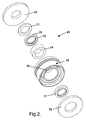
- FIG. 2 is an exploded view of the rod guide assembly 43 .
- the rod guide assembly 43 may include a seal cover 70 , a retaining ring 71 , a fluid seal 72 including an energizer 73 , a low-friction bearing 74 , a housing assembly 75 including an aperture 76 formed therein, a scraper seal 77 , and a retainer 78 .
- the scraper seal 77 may be omitted to reduce part number and assembly cost.
- FIG. 3 is a detailed cross-sectional view of the rod guide assembly 43 shown assembled.
- Housing assembly 75 includes an outer housing 85 with a compliant member 79 positioned adjacent a sleeve 80 .
- Compliant member 79 may be manufactured from a resilient material such as rubber, plastic, acrylic, silicone, vinyl, urethane, and the like.
- the compliant member 79 material is a rubber bonded to the outer housing 85 and the sleeve 80 and is compatible with the damper conditions (e.g., high temperature and pressure) and the fluid type.
- Compliant member 79 may include an annular opening 83 in which fluid is carried.
- the annular opening 83 allows the compliant member 79 to compress and expand laterally (i.e., along arrows A ). Fluid may move out of and into the annular opening 83 as the compliant member 79 compresses and expands, respectively.
- Bearing 74 is positioned within the aperture 76 , receives the piston rod 26 (as shown in FIG. 1), and engages the sleeve 80 .
- Bearing 74 may be manufactured from a low-friction material such as Teflon, plastic, steel, aluminum, metal, metal alloy, and the like.
- the bearing 74 material preferably allows the piston rod 26 (as shown in FIG.1) to slide axially (i.e., along arrows B ) with minimal friction.
- the bearing 74 may be manufactured from steel, plated with Teflon impregnated nickel for reduced sliding friction and improved corrosion resistance.
- Fluid seal 72 and scraper seal 77 are positioned within the aperture 76 .
- Fluid seal 72 may be positioned between the retaining ring 71 and the bearing 74 .
- Scraper seal 77 may be positioned between the bearing 74 and the retainer 78 .
- Fluid seal 72 and scraper seal 77 may be adapted to engage the piston rod 26 and prevent the ingress of MR fluid particles, thus lessening axial friction and promoting the lifetime of the part.
- Energizer 73 may provide a biasing force against the fluid seal 72 causing projections 81 to effectively engage the piston rod 26 .
- Seal cover 70 and a retainer 78 are operably attached to the housing assembly 75 and may retain the bearing 74 and seals 72 , 77 within the aperture 76 .
- a static O-ring 82 may be disposed within an outer groove 84 of the housing assembly 75 . O-ring 82 creates a seal between the outside of the housing assembly 75 and the inside of the damper body tube 40 .
- the piston rod 26 may move laterally causing the bearing 74 and sleeve 80 to move in the same direction.
- the compliant member 79 is deformed (e.g., expand and compress) thereby allowing a lateral range of motion for the bearing 74 and sleeve 80 .
- the bearing 74 and sleeve 80 are able to move in accordance with the piston rod 26 thereby compensating for lateral movement of the piston rod 26 produced by side-loads.
- the bearing 74 and sleeve 80 are able to move laterally with relative ease (i.e., only having to overcome relatively small static friction forces) thereby allowing the rod guide assembly 43 to better compensate for smaller side-loads. As such, binding contact of the piston assembly 25 with the damper body tube 40 and unnecessary strut 10 wear may be prevented.
- the strut and rod guide assembly are not limited to any particular design, configuration, or arrangement.
- the housing assembly, bearing, seals, seal cover and retainer configuration, size, shape, geometry, location, orientation, and number, may vary without limiting the utility of the invention.
- the strut and rod guide assembly are not limited to MR-type monotube dampers. Those skilled in the art will recognize that the invention may be adapted for numerous damper types.
Abstract
Description
- The present invention relates to monotube strut assemblies, and more particularly to a floating rod guide for a monotube strut.
- A strut is a type of damper that is used in vehicle suspensions as both a damping device for providing shock absorbing functions and as part of the suspension's load-bearing structure. Monotube gas-charged dampers are known wherein a piston with a connected piston rod is slidably carried in a fluid-filled tube with a separate piston called a gas cup slidably carried in the tube on an opposite side of the piston from the rod. The gas cup separates a compressible gas charge from the fluid within the damper. It is known that monotube gas-charged dampers exhibit desirable performance characteristics when used in some suspension assemblies.
- Typically, the generic monotube strut design configuration is produced primarily as an aftermarket replacement damper, although limited original equipment (OEM) applications have been implemented. The prior art device generally includes a bearing mechanism that includes a combination of a polytetrafluoroethelyne laminated plain bearing and a grease lubricant. In some applications performance advantages of high pressure monotube dampers are well known and therefore, the use of such devices without restriction would be desirable. However, in applying a monotube gas-charged strut in an OEM application, extended durability requirements may lead to restrictions in the use of such devices, particularly in applications involving larger and heavier vehicles that operate with resultant increased side-loading. In particular, such a strut must be assembled and maintained in a straight and true line otherwise, misalignment may lead to premature rod wear and high damper axial friction. Accordingly, it would be desirable to provide a strategy for minimizing rod wear and damper axial friction due to misalignment in a monotube strut.
- One strategy developed for minimizing rod wear and damper axial friction in a monotube strut is disclosed in U.S. Patent No. 6,390,258 to Hofmann et al., which is incorporated by reference herein. The Hofmann patent teaches a floating rod guide assembly including a rod guide, a seal cover, and a retainer. A first O-ring is disposed between the seal cover and the rod guide, and a second O-ring is disposed between the rod guide and the retainer. During operation, a damper rod slides within a passageway provided in the guide assembly. The guide assembly may reduce friction levels and incidence of premature rod wear by compensating for side-load forces exerted on the strut.
- Although the guide assembly may effectively reduce friction levels and incidence of premature rod wear with larger side-loads, some wear may occur with smaller side-loads. The prior art strut typically requires that a sufficient side-load is exerted on the assembly to overcome static friction forces associated with the O-rings. Unless the static friction forces are overcome, the rod guide is not free to move laterally to compensate for the smaller side-loads. This may cause binding contact of the piston with other surfaces thereby resulting in premature wear and failure. Accordingly, it would be desirable to provide a floating rod guide that can compensate for smaller side-loads.
- Therefore, it would be desirable to provide a floating rod guide that overcomes the aforementioned and other disadvantages.
- A first aspect of the present invention provides a guide assembly for a rod of a motor vehicle strut. The guide assembly includes a housing assembly with a compliant member positioned adjacent a sleeve. A bearing receives the rod, is positioned substantially within the aperture, and engages the sleeve. At least one seal is positioned substantially within the aperture. A seal cover and a retainer are operably attached to the housing assembly. Lateral movement of the rod causes deformation of the compliant member.
- A second aspect of the present invention provides a strut for a motor vehicle. The strut includes a body, a rod slidable within the body, and a guide assembly. The guide assembly includes the aforementioned features and functions described in the first aspect of the invention.
- A third aspect of the present invention provides a guide assembly for a rod of a motor vehicle strut. The guide assembly includes housing means and means for slidably receiving the rod within the housing means. The guide assembly further includes means for providing lateral movement of the rod within the housing means and means for sealing the rod.
- The foregoing and other features and advantages of the invention will become further apparent from the following detailed description of the presently preferred embodiments, read in conjunction with the accompanying drawings. The detailed description and drawings are merely illustrative of the invention, rather than limiting the scope of the invention being defined by the appended claims and equivalents thereof.
-
- FIG. 1 is a cross-sectional view of a monotube strut including a rod guide assembly in accordance with the present invention;
- FIG. 2 is an exploded view of the rod guide assembly shown in FIG. 1; and
- FIG. 3 is a detailed cross-sectional view of the rod guide assembly shown in FIG. 1.
-
- Referring to the drawings, wherein like reference numerals refer to like elements, FIG. 1 is a cross-sectional view of a monotube strut made in accordance with the present invention and shown generally by
numeral 10. Those skilled in the art will recognize that thestrut 10 may include a number of alternate damper designs and may be employed in a variety of applications. In the present description, thestrut 10 is shown and described as a linear acting fluid magnetorheological (MR) damper for generating dampening forces in a motor vehicle suspension system. -
Strut 10 includes abody 12 that may include ahousing tube 14 with anopen end 15 and a closedend 16 that may be formed by a spin closing operation, or by welding or otherwise securing asecondary component 39 to thehousing tube 14. Closedend 16 may include anopening 17. Amounting bracket 18 may include acylindrical body 19 that is closely received over thehousing tube 14 near closedend 16 and may be secured in position by a suitable means such as welding.Bracket 18 may include a pair ofarms 20 that exhibit suitable openings for connection to the unsprung mass of the vehicle at a location such as the steering knuckle (not illustrated). Aspring seat 21 may be received on thehousing tube 14 and located in position as required by the particular application within which thestrut 10 will operate.Spring seat 21 may be fixed in position on thehousing tube 14 by a suitable means such as welding. Further details of the housing tube are described in U.S. Pat. No. 5,984,060, the disclosure of which is hereby incorporated by reference. - A
piston assembly 25 may be slidably positioned within thehousing tube 14 and connected to apiston rod 26. Pistonrod 26 may extend through theopening 17 and include a threadedportion 27 for attachment to thehousing tube 14. Pistonassembly 25 may include anannular gap 28 having a substantially circular ring cross-sectional shape to allow fluid to pass therethrough. Pistonassembly 25 may include acoil 29 for generating an electromagnetic field within a portion of theannular gap 28.Coil 29 may include one or more conductive elements, such as a metallic wire, for carrying an electric current. Anelectrical conductor 30 may extend through thepiston rod 26 for providing electrical current to thecoil 29 from an external power source (not shown). The electric current may be provided and controlled externally (e.g., by an electrical source and vehicle computer system) to dynamically regulate dampening forces. Specifically, the magnetic field generated by thecoil 29 excites a transformation of MR fluids to a state that exhibits increased damping force (i.e., the MR fluid viscosity is increased). The dampening force is thus proportional to the amount of current run through thecoil 29. - A
damper body tube 40 may be slidable received about thepiston assembly 25.Damper body tube 40 may include afirst end 41 at an outboard position adapted to be connected to the sprung mass of the vehicle and include asecond end 42 at an inboard position.Second end 42 may be supported about thepiston rod 26 by a floatingrod guide assembly 43 that is fixed in position within thedamper body tube 40. The upper end of therod guide assembly 43 may be adapted to contact a rebound stop that includes one or more, in this case three,elastomeric bushings 45 carried adjacent thepiston assembly 25. At maximum extension of thestrut 10, thebushings 45 may be compressed against the upper end of therod guide assembly 43 to cushion the deceleration ofstrut 10. Aplate 46 may be carried near therod guide assembly 43 by abracket 51 positioned adjacent theend 42 ofdamper body tube 40.Plate 46 may be adapted to contact ajounce bumper 47 that includes an elastomeric bushing and is positioned against theclosed end 16 ofhousing tube 14 and about thepiston rod 26. - A
gas cup 48 may be carried in thedamper body tube 40 between thepiston assembly 25 and theend 41.Gas cup 48 may carry a seal and slide along the inside ofdamper body tube 40 separating acompensation chamber 49 from thecompression chamber 37.Extension chamber 36 andcompression chamber 37 may carry a supply of hydraulic fluid, such as MR fluid.Compensation chamber 49 may carry a compressible fluid, such as nitrogen gas. During extension and compression directed travel of thedamper body tube 40 relative to thepiston assembly 25, a decreasing or an increasing volume of thepiston rod 26 may be contained within thedamper body tube 40 depending on the stroke position of thestrut assembly 10. In order to compensate for this varying volumetric amount of thepiston rod 26 within the fluid-filledchambers gas cup 48 slides compressing or expanding thecompensation chamber 49. -
Damper body tube 40 may be supported within thehousing tube 14 by a bearingsystem 52 that is designed to reduce friction and improve durability of thestrut 10.Bearing system 52 may include a bearingsleeve 53 manufactured from a material such as steel and may include astep 54 formed near itsoutboard end 56 and astep 55 formed near itsinboard end 57. Bearingsleeve 53 may be slip-fit within thehousing tube 14 nearend 15. Bearingsleeve 53 may be maintained in position by a formedstop 59 atend 57, and by a retainingcap 60 atend 56 that is pressed onto the end ofhousing tube 14.Stop 59 may be formed by a means such as roll-forming or dimpling. - Bearing
assembly 52 may also includes a pair ofplain bearings sleeve 53 with the bearing 61 positioned nearend 56 and thebearing 62 positioned nearend 57. Aseal 63 may be positioned against thestep 54 and bear against thedamper body tube 40. Aseal 64 may be positioned against thestep 55 and bear against thedamper body tube 40. This provides a fluid-tight chamber 65 between thebearings chamber 65 may be in a fluid form at room temperature and is preferably comprised of a formulated synthetic hydrocarbon based polyalphaolefinic bearing oil. This preferred oil is selected because it provides the film strength of natural paraffinic petroleum oil with improved performance in the areas of volatility, temperature, operating range, and viscosity stability. -
Body 12,housing tube 14,damper body tube 40,piston rod 26, and portions thereof may be manufactured from a variety of sufficiently rigid material(s) such as steel, aluminum, metal, metal alloy, composites, and the like.Piston assembly 25 may be formed from low-carbon steel. Low-carbon steel materials typically provide electro-magnetic induction properties compatible with MR fluids. Those skilled in the art will recognize that the design and nature of the constituent materials of thestrut 10 may vary without limiting the operation of the present invention. - FIG. 2 is an exploded view of the
rod guide assembly 43. In one embodiment, therod guide assembly 43 may include aseal cover 70, a retainingring 71, afluid seal 72 including anenergizer 73, a low-friction bearing 74, ahousing assembly 75 including anaperture 76 formed therein, ascraper seal 77, and aretainer 78. In another embodiment, as for use with low temperature damper applications, thescraper seal 77 may be omitted to reduce part number and assembly cost. Those skilled in the art will recognize that rod guide assembly parts and manner in which they are configured may vary while providing the advantages of the present invention. - FIG. 3 is a detailed cross-sectional view of the
rod guide assembly 43 shown assembled.Housing assembly 75 includes anouter housing 85 with acompliant member 79 positioned adjacent asleeve 80.Compliant member 79 may be manufactured from a resilient material such as rubber, plastic, acrylic, silicone, vinyl, urethane, and the like. In one embodiment, thecompliant member 79 material is a rubber bonded to theouter housing 85 and thesleeve 80 and is compatible with the damper conditions (e.g., high temperature and pressure) and the fluid type.Compliant member 79 may include anannular opening 83 in which fluid is carried. Theannular opening 83 allows thecompliant member 79 to compress and expand laterally (i.e., along arrows A). Fluid may move out of and into theannular opening 83 as thecompliant member 79 compresses and expands, respectively. -
Bearing 74 is positioned within theaperture 76, receives the piston rod 26 (as shown in FIG. 1), and engages thesleeve 80.Bearing 74 may be manufactured from a low-friction material such as Teflon, plastic, steel, aluminum, metal, metal alloy, and the like. The bearing 74 material preferably allows the piston rod 26 (as shown in FIG.1) to slide axially (i.e., along arrows B) with minimal friction. In one embodiment, the bearing 74 may be manufactured from steel, plated with Teflon impregnated nickel for reduced sliding friction and improved corrosion resistance. -
Fluid seal 72 andscraper seal 77 are positioned within theaperture 76.Fluid seal 72 may be positioned between the retainingring 71 and thebearing 74.Scraper seal 77 may be positioned between the bearing 74 and theretainer 78.Fluid seal 72 andscraper seal 77 may be adapted to engage thepiston rod 26 and prevent the ingress of MR fluid particles, thus lessening axial friction and promoting the lifetime of the part.Energizer 73 may provide a biasing force against thefluid seal 72 causingprojections 81 to effectively engage thepiston rod 26.Seal cover 70 and aretainer 78 are operably attached to thehousing assembly 75 and may retain thebearing 74 and seals 72, 77 within theaperture 76. A static O-ring 82 may be disposed within anouter groove 84 of thehousing assembly 75. O-ring 82 creates a seal between the outside of thehousing assembly 75 and the inside of thedamper body tube 40. - When a side-load is exerted on the
strut 10, thepiston rod 26 may move laterally causing thebearing 74 andsleeve 80 to move in the same direction. As thesleeve 80 moves laterally, thecompliant member 79 is deformed (e.g., expand and compress) thereby allowing a lateral range of motion for thebearing 74 andsleeve 80. Accordingly, thebearing 74 andsleeve 80 are able to move in accordance with thepiston rod 26 thereby compensating for lateral movement of thepiston rod 26 produced by side-loads. Thebearing 74 andsleeve 80 are able to move laterally with relative ease (i.e., only having to overcome relatively small static friction forces) thereby allowing therod guide assembly 43 to better compensate for smaller side-loads. As such, binding contact of thepiston assembly 25 with thedamper body tube 40 andunnecessary strut 10 wear may be prevented. - While the embodiments of the invention disclosed herein are presently considered to be preferred, various changes and modifications can be made without departing from the spirit and scope of the invention. For example, the strut and rod guide assembly are not limited to any particular design, configuration, or arrangement. The housing assembly, bearing, seals, seal cover and retainer configuration, size, shape, geometry, location, orientation, and number, may vary without limiting the utility of the invention. Furthermore, the strut and rod guide assembly are not limited to MR-type monotube dampers. Those skilled in the art will recognize that the invention may be adapted for numerous damper types.
- Upon reading the specification and reviewing the drawings hereof, it will become immediately obvious to those skilled in the art that myriad other embodiments of the present invention are possible, and that such embodiments are contemplated and fall within the scope of the presently claimed invention. The scope of the invention is indicated in the appended claims, and all changes that come within the meaning and range of equivalents are intended to be embraced therein.
Claims (21)
- A guide assembly 43 for a rod 26 of a motor vehicle strut 10, the guide assembly 43 comprising:a housing assembly 75 including a compliant member 79 positioned adjacent a sleeve 80, the housing assembly 75 including an aperture 76 formed therein;a bearing 74 for receiving the rod 26, the bearing 74 positioned substantially within the aperture 76 and engaging the sleeve 80;at least one seal 72, 77 positioned substantially within the aperture 76; anda seal cover 70 and a retainer 78 operably attached to the housing assembly 75; wherein lateral movement of the rod 26 causes deformation of the compliant member 79.
- The guide assembly 43 of claim 1 wherein the seal comprises a scraper seal 77 for engaging the rod 26 of the motor vehicle strut 10.
- The guide assembly 43 of claim 1 wherein the seal comprises a fluid seal 72 including an energizer 73, the fluid seal 72 for engaging the rod 26 of the motor vehicle strut 10.
- The guide assembly 43 of claim 1 wherein the compliant member 79 comprises a resilient material.
- The guide assembly 43 of claim 4 wherein the resilient material comprises at least one material selected from a group consisting of rubber, plastic, acrylic, silicone, vinyl, and urethane.
- The guide assembly 43 of claim 1 wherein the compliant member 79 defines at least one opening 83 formed therein for carrying a fluid.
- The guide assembly 43 of claim 1 wherein the bearing 74 comprises a low-friction material.
- The guide assembly 43 of claim 1 wherein the low-friction material comprises at least one material selected from a group consisting of Teflon, plastic, steel, aluminum, metal, and metal alloy.
- The guide assembly 43 of claim 1 further comprising a retaining ring 71 operably attached to the housing assembly 75.
- The guide assembly 43 of claim 1 further comprising an O-ring 82 disposed adjacent an outer groove 84 of the housing assembly 75.
- A strut 10 for a motor vehicle, the strut 10 comprising:a body 12;a rod 26 slidable within the bedy 12; anda guide assembly 43 including:a housing assembly 75 including a compliant member 79 positioned adjacent a sleeve 80, the housing assembly 75 including an aperture 76 formed therein;a bearing 74 for receiving the rod 26, the bearing 74 positioned substantially within the aperture 76 and engaging the sleeve 80;at least one seal 72, 77 positioned substantially within the aperture 76; anda seal cover 70 and a retainer 78 operably attached to the housing assembly 75; wherein lateral movement of the rod 26 causes deformation of the compliant member 79.
- The strut 10 of claim 11 wherein the seal comprises a scraper seal 77 for engaging the rod 26 of the motor vehicle strut 10.
- The strut 10 of claim 11 wherein the seal comprises a fluid seal 72 including an energizer 73, the fluid seal 72 for engaging the rod 26 of the motor vehicle strut 10.
- The strut 10 of claim 11 wherein the compliant member 79 comprises a resilient material.
- The strut 10 of claim 14 wherein the resilient material comprises at least one material selected from a group consisting of rubber, plastic, acrylic, silicone, vinyl, and urethane.
- The strut 10 of claim 11 wherein the compliant member 79 defines at least one opening 83 formed therein for carrying a fluid.
- The strut 10 of claim 11 wherein the bearing 74 comprises a low-friction material.
- The strut 10 of claim 17 wherein the low-friction material comprises at least one material selected from a group consisting of Teflon, plastic, steel, aluminum, metal, and metal alloy.
- The strut 10 of claim 11 further comprising a retaining ring 71 operably attached to the housing assembly 75.
- The strut 10 of claim 11 further comprising an O-ring 82 disposed adjacent an outer groove 84 of the housing assembly 75.
- A guide assembly 43 for a rod 26 of a motor vehicle strut 10, the guide assembly 43 comprising:guide means 75;means 74 for slidably receiving the rod 26 within the guide means 75;means 79, 80 for providing lateral movement of the rod 26 within the guide means 75; andmeans 72, 77 for sealing the rod 26.
Applications Claiming Priority (2)
| Application Number | Priority Date | Filing Date | Title |
|---|---|---|---|
| US339471 | 2003-01-09 | ||
| US10/339,471 US6840358B2 (en) | 2003-01-09 | 2003-01-09 | Floating rod guide for monotube strut |
Publications (3)
| Publication Number | Publication Date |
|---|---|
| EP1437523A2 true EP1437523A2 (en) | 2004-07-14 |
| EP1437523A3 EP1437523A3 (en) | 2005-04-13 |
| EP1437523B1 EP1437523B1 (en) | 2007-06-20 |
Family
ID=32507464
Family Applications (1)
| Application Number | Title | Priority Date | Filing Date |
|---|---|---|---|
| EP03078890A Expired - Fee Related EP1437523B1 (en) | 2003-01-09 | 2003-12-08 | Floating rod guide for monotube strut |
Country Status (3)
| Country | Link |
|---|---|
| US (1) | US6840358B2 (en) |
| EP (1) | EP1437523B1 (en) |
| DE (1) | DE60314492T2 (en) |
Cited By (3)
| Publication number | Priority date | Publication date | Assignee | Title |
|---|---|---|---|---|
| EP1681491A1 (en) * | 2005-01-17 | 2006-07-19 | Delphi Technologies, Inc. | Magneto-rheological hydraulic damper |
| WO2015067364A1 (en) * | 2013-11-06 | 2015-05-14 | Carl Freudenberg Kg | Wiper arrangement and/or sealing arrangement, and wiper and/or sealing ring therefor |
| CN105041954A (en) * | 2015-07-19 | 2015-11-11 | 湖南城市学院 | Intelligent adjustable vibration reduction device |
Families Citing this family (18)
| Publication number | Priority date | Publication date | Assignee | Title |
|---|---|---|---|---|
| ITTO20040319A1 (en) * | 2004-05-14 | 2004-08-14 | Skf Ab | VEHICLE POST |
| GB2418001A (en) * | 2004-09-09 | 2006-03-15 | Tenneco Automotive Operating | A piston and cylinder strut assembly in which an end of the piston rod defines a contoured surface |
| JP2006234070A (en) * | 2005-02-25 | 2006-09-07 | Kayaba Ind Co Ltd | Single cylinder-shaped hydraulic damper |
| US20060260891A1 (en) * | 2005-05-17 | 2006-11-23 | Kruckemeyer William C | Magnetorheological piston assembly and damper |
| US20080067019A1 (en) * | 2006-09-19 | 2008-03-20 | Delphi Technologies, Inc. | Magnetorheological damper |
| US20080314707A1 (en) * | 2007-06-20 | 2008-12-25 | Saiman Lun | Damper having a rebound bumper and damper subassembly having same |
| DE102007030641B3 (en) * | 2007-07-02 | 2008-10-02 | Thyssenkrupp Bilstein Suspension Gmbh | Height adjustable vibration damper |
| US20100116607A1 (en) | 2008-11-07 | 2010-05-13 | Saiman Lun | Dual seal rod guide assembly with low friction disc |
| DE102009016824A1 (en) * | 2009-04-09 | 2010-10-14 | Rudolf Lonski | Friction damper with housing, in particular for drum washing machines with spin cycle |
| CN102235456B (en) * | 2010-04-26 | 2013-11-06 | 京西重工股份有限公司 | Double-seal rod guidance assembly with low-friction disc |
| DE102012016948A1 (en) * | 2012-08-28 | 2014-03-06 | Inventus Engineering Gmbh | Damper with one-way circuit and method |
| DE102013109374B4 (en) * | 2013-08-29 | 2020-04-23 | Knorr-Bremse Systeme für Schienenfahrzeuge GmbH | Brake cylinder with rod seal arrangement |
| DE102014223164B4 (en) * | 2014-11-13 | 2022-03-17 | Zf Friedrichshafen Ag | seal guiding unit |
| US10072723B2 (en) * | 2015-04-24 | 2018-09-11 | Beijingwest Industries Co., Ltd. | Closing assembly for a magneto-rheological damper |
| US10399402B2 (en) | 2016-06-30 | 2019-09-03 | Beijingwest Industries Co., Ltd. | Strut assembly including a bearing sleeve having a radial protrusion |
| US10487901B2 (en) * | 2017-01-09 | 2019-11-26 | Beijingwest Industries Co., Ltd. | Damping strut |
| US20210088144A1 (en) * | 2019-09-20 | 2021-03-25 | United Technologies Corporation | Self-centering seal and method of using same |
| US11855379B2 (en) * | 2021-11-24 | 2023-12-26 | Caterpillar Inc. | Slidable nested conductors |
Citations (1)
| Publication number | Priority date | Publication date | Assignee | Title |
|---|---|---|---|---|
| US6390258B1 (en) | 2001-07-27 | 2002-05-21 | Delphi Technologies, Inc. | Floating rod guide for monotube strut |
Family Cites Families (13)
| Publication number | Priority date | Publication date | Assignee | Title |
|---|---|---|---|---|
| US3979134A (en) * | 1974-05-02 | 1976-09-07 | Monroe Belgium N.V. | Vehicle suspension system |
| US4765227A (en) * | 1982-05-28 | 1988-08-23 | Teledyne Hyson | Die cylinder assembly |
| US5363945A (en) * | 1988-08-01 | 1994-11-15 | Monroe Auto Equipment Company | Control valve for shock absorbers |
| JP2517808Y2 (en) * | 1990-05-10 | 1996-11-20 | 株式会社ユニシアジェックス | Rod guide for double cylinder type hydraulic shock absorber |
| US5129635A (en) * | 1990-06-21 | 1992-07-14 | Power Components, Inc. | Gas spring with c-shaped seal |
| FR2709796B1 (en) * | 1993-08-06 | 1998-11-27 | Carbon Ste Fse Amortisseurs | One-piece sealing device with lubricated centering guide for pressurized hydraulic shock absorber tube. |
| US5984060A (en) | 1997-08-25 | 1999-11-16 | General Motors Corporation | Monotube strut assembly |
| DE19938084B4 (en) * | 1998-12-11 | 2005-11-24 | Daimlerchrysler Ag | Guide bearing in connection with a pressure cylinder, in particular damping element for motor vehicles |
| US6318526B1 (en) * | 1999-09-13 | 2001-11-20 | Delphi Technologies, Inc. | Compliant rod guide and seal assembly |
| JP2001295876A (en) * | 2000-04-10 | 2001-10-26 | Yamaha Motor Co Ltd | Hydraulic shock absorber for vehicle |
| US6454060B1 (en) | 2001-03-21 | 2002-09-24 | Delphi Technologies, Inc. | Vehicle suspension monotube strut base cup assembly |
| US6510930B2 (en) | 2001-04-30 | 2003-01-28 | Delphi Technologies, Inc. | Floating rod guide |
| US6640943B1 (en) * | 2002-08-13 | 2003-11-04 | Fox Factory, Inc. | Shock absorber with sealing ice scraper |
-
2003
- 2003-01-09 US US10/339,471 patent/US6840358B2/en not_active Expired - Lifetime
- 2003-12-08 DE DE60314492T patent/DE60314492T2/en not_active Expired - Lifetime
- 2003-12-08 EP EP03078890A patent/EP1437523B1/en not_active Expired - Fee Related
Patent Citations (1)
| Publication number | Priority date | Publication date | Assignee | Title |
|---|---|---|---|---|
| US6390258B1 (en) | 2001-07-27 | 2002-05-21 | Delphi Technologies, Inc. | Floating rod guide for monotube strut |
Cited By (3)
| Publication number | Priority date | Publication date | Assignee | Title |
|---|---|---|---|---|
| EP1681491A1 (en) * | 2005-01-17 | 2006-07-19 | Delphi Technologies, Inc. | Magneto-rheological hydraulic damper |
| WO2015067364A1 (en) * | 2013-11-06 | 2015-05-14 | Carl Freudenberg Kg | Wiper arrangement and/or sealing arrangement, and wiper and/or sealing ring therefor |
| CN105041954A (en) * | 2015-07-19 | 2015-11-11 | 湖南城市学院 | Intelligent adjustable vibration reduction device |
Also Published As
| Publication number | Publication date |
|---|---|
| DE60314492D1 (en) | 2007-08-02 |
| EP1437523B1 (en) | 2007-06-20 |
| DE60314492T2 (en) | 2008-02-14 |
| US20040134731A1 (en) | 2004-07-15 |
| EP1437523A3 (en) | 2005-04-13 |
| US6840358B2 (en) | 2005-01-11 |
Similar Documents
| Publication | Publication Date | Title |
|---|---|---|
| US6840358B2 (en) | Floating rod guide for monotube strut | |
| US6390258B1 (en) | Floating rod guide for monotube strut | |
| US6547044B2 (en) | Magneto-rheological damper with ferromagnetic housing insert | |
| US6883649B2 (en) | Closing system for a magneto-rheological damper | |
| US5984060A (en) | Monotube strut assembly | |
| US6336535B1 (en) | Magneto-rheological damper with dual flux ring spacer | |
| US6382369B1 (en) | Magneto-rheological fluid damper with an external coil | |
| US4921223A (en) | Car suspension system | |
| US7232016B2 (en) | Fluid damper having continuously variable damping response | |
| US6497309B1 (en) | Magneto-rheological damper with an external coil | |
| EP1065405A1 (en) | Guiding and sealing device for dampers using electrorheological fluids | |
| CN114810911B (en) | Stroke dependent damper assembly | |
| US9533538B2 (en) | Low pressure high compression damping monotube shock absorber | |
| US20070051574A1 (en) | Rod guide seal | |
| CN1871452A (en) | Stroke dependent bypass | |
| US6637560B2 (en) | Vehicle damper assembly and method of modulating fluid flow | |
| JP6503510B2 (en) | Cylinder device and method of manufacturing the same | |
| US20020130002A1 (en) | Gas cup seal for magneto-rheological damper | |
| US5535862A (en) | Suspension strut with quiet rebound stop | |
| US7252031B2 (en) | Cylinder apparatus | |
| US20040124051A1 (en) | Vehicle suspension damper having a bouyant sleeve for limiting rebound | |
| US20060219505A1 (en) | Shock absorber including supplemental friction generating device | |
| CN210599992U (en) | Piston assembly in double-rod current variable damper | |
| CN218971727U (en) | Tandem spring structure | |
| CN210599991U (en) | Electrode assembly in double-rod current variable damper |
Legal Events
| Date | Code | Title | Description |
|---|---|---|---|
| PUAI | Public reference made under article 153(3) epc to a published international application that has entered the european phase |
Free format text: ORIGINAL CODE: 0009012 |
|
| AK | Designated contracting states |
Kind code of ref document: A2 Designated state(s): AT BE BG CH CY CZ DE DK EE ES FI FR GB GR HU IE IT LI LU MC NL PT RO SE SI SK TR |
|
| AX | Request for extension of the european patent |
Extension state: AL LT LV MK |
|
| PUAL | Search report despatched |
Free format text: ORIGINAL CODE: 0009013 |
|
| AK | Designated contracting states |
Kind code of ref document: A3 Designated state(s): AT BE BG CH CY CZ DE DK EE ES FI FR GB GR HU IE IT LI LU MC NL PT RO SE SI SK TR |
|
| AX | Request for extension of the european patent |
Extension state: AL LT LV MK |
|
| 17P | Request for examination filed |
Effective date: 20051013 |
|
| AKX | Designation fees paid |
Designated state(s): DE FR GB |
|
| GRAP | Despatch of communication of intention to grant a patent |
Free format text: ORIGINAL CODE: EPIDOSNIGR1 |
|
| GRAS | Grant fee paid |
Free format text: ORIGINAL CODE: EPIDOSNIGR3 |
|
| GRAA | (expected) grant |
Free format text: ORIGINAL CODE: 0009210 |
|
| AK | Designated contracting states |
Kind code of ref document: B1 Designated state(s): DE FR GB |
|
| REG | Reference to a national code |
Ref country code: GB Ref legal event code: FG4D |
|
| REF | Corresponds to: |
Ref document number: 60314492 Country of ref document: DE Date of ref document: 20070802 Kind code of ref document: P |
|
| EN | Fr: translation not filed | ||
| PLBE | No opposition filed within time limit |
Free format text: ORIGINAL CODE: 0009261 |
|
| STAA | Information on the status of an ep patent application or granted ep patent |
Free format text: STATUS: NO OPPOSITION FILED WITHIN TIME LIMIT |
|
| 26N | No opposition filed |
Effective date: 20080325 |
|
| PG25 | Lapsed in a contracting state [announced via postgrant information from national office to epo] |
Ref country code: FR Free format text: LAPSE BECAUSE OF FAILURE TO SUBMIT A TRANSLATION OF THE DESCRIPTION OR TO PAY THE FEE WITHIN THE PRESCRIBED TIME-LIMIT Effective date: 20080222 |
|
| GBPC | Gb: european patent ceased through non-payment of renewal fee |
Effective date: 20071208 |
|
| PG25 | Lapsed in a contracting state [announced via postgrant information from national office to epo] |
Ref country code: GB Free format text: LAPSE BECAUSE OF NON-PAYMENT OF DUE FEES Effective date: 20071208 |
|
| PGFP | Annual fee paid to national office [announced via postgrant information from national office to epo] |
Ref country code: DE Payment date: 20181127 Year of fee payment: 16 |
|
| REG | Reference to a national code |
Ref country code: DE Ref legal event code: R081 Ref document number: 60314492 Country of ref document: DE Owner name: BWI COMPANY LIMITED S.A., LU Free format text: FORMER OWNER: DELPHI TECHNOLOGIES, INC., TROY, MICH., US Ref country code: DE Ref legal event code: R082 Ref document number: 60314492 Country of ref document: DE |
|
| REG | Reference to a national code |
Ref country code: DE Ref legal event code: R119 Ref document number: 60314492 Country of ref document: DE |
|
| PG25 | Lapsed in a contracting state [announced via postgrant information from national office to epo] |
Ref country code: DE Free format text: LAPSE BECAUSE OF NON-PAYMENT OF DUE FEES Effective date: 20200701 |