EP1437498A1 - 4−STROKE ENGINE CONTROL DEVICE AND CONTROL METHOD - Google Patents
4−STROKE ENGINE CONTROL DEVICE AND CONTROL METHOD Download PDFInfo
- Publication number
- EP1437498A1 EP1437498A1 EP02746022A EP02746022A EP1437498A1 EP 1437498 A1 EP1437498 A1 EP 1437498A1 EP 02746022 A EP02746022 A EP 02746022A EP 02746022 A EP02746022 A EP 02746022A EP 1437498 A1 EP1437498 A1 EP 1437498A1
- Authority
- EP
- European Patent Office
- Prior art keywords
- pressure
- fuel
- intake
- fuel injection
- detected
- Prior art date
- Legal status (The legal status is an assumption and is not a legal conclusion. Google has not performed a legal analysis and makes no representation as to the accuracy of the status listed.)
- Granted
Links
- 238000000034 method Methods 0.000 title claims description 24
- 239000000446 fuel Substances 0.000 claims abstract description 324
- 238000002347 injection Methods 0.000 claims abstract description 188
- 239000007924 injection Substances 0.000 claims abstract description 188
- 239000002828 fuel tank Substances 0.000 claims abstract description 16
- 230000001105 regulatory effect Effects 0.000 claims abstract description 9
- 238000002485 combustion reaction Methods 0.000 claims description 20
- 230000006835 compression Effects 0.000 claims description 12
- 238000007906 compression Methods 0.000 claims description 12
- 230000001276 controlling effect Effects 0.000 claims description 11
- 230000000977 initiatory effect Effects 0.000 claims description 10
- 230000008569 process Effects 0.000 description 10
- 230000007704 transition Effects 0.000 description 10
- 230000008859 change Effects 0.000 description 9
- 238000004519 manufacturing process Methods 0.000 description 7
- 238000010586 diagram Methods 0.000 description 5
- 239000000498 cooling water Substances 0.000 description 4
- 230000006870 function Effects 0.000 description 4
- 230000004044 response Effects 0.000 description 3
- 230000001133 acceleration Effects 0.000 description 2
- 238000004364 calculation method Methods 0.000 description 2
- 230000007423 decrease Effects 0.000 description 2
- 238000001514 detection method Methods 0.000 description 2
- 238000000429 assembly Methods 0.000 description 1
- 230000000712 assembly Effects 0.000 description 1
- 230000002596 correlated effect Effects 0.000 description 1
- 230000000875 corresponding effect Effects 0.000 description 1
- 238000002474 experimental method Methods 0.000 description 1
- 239000003502 gasoline Substances 0.000 description 1
- 208000015181 infectious disease Diseases 0.000 description 1
- 230000010354 integration Effects 0.000 description 1
- 238000005259 measurement Methods 0.000 description 1
- 230000009467 reduction Effects 0.000 description 1
- 238000004088 simulation Methods 0.000 description 1
- 238000005303 weighing Methods 0.000 description 1
Images


Classifications
-
- F—MECHANICAL ENGINEERING; LIGHTING; HEATING; WEAPONS; BLASTING
- F02—COMBUSTION ENGINES; HOT-GAS OR COMBUSTION-PRODUCT ENGINE PLANTS
- F02D—CONTROLLING COMBUSTION ENGINES
- F02D41/00—Electrical control of supply of combustible mixture or its constituents
- F02D41/30—Controlling fuel injection
- F02D41/32—Controlling fuel injection of the low pressure type
- F02D41/34—Controlling fuel injection of the low pressure type with means for controlling injection timing or duration
- F02D41/345—Controlling injection timing
-
- F—MECHANICAL ENGINEERING; LIGHTING; HEATING; WEAPONS; BLASTING
- F02—COMBUSTION ENGINES; HOT-GAS OR COMBUSTION-PRODUCT ENGINE PLANTS
- F02D—CONTROLLING COMBUSTION ENGINES
- F02D2200/00—Input parameters for engine control
- F02D2200/02—Input parameters for engine control the parameters being related to the engine
- F02D2200/04—Engine intake system parameters
- F02D2200/0402—Engine intake system parameters the parameter being determined by using a model of the engine intake or its components
-
- F—MECHANICAL ENGINEERING; LIGHTING; HEATING; WEAPONS; BLASTING
- F02—COMBUSTION ENGINES; HOT-GAS OR COMBUSTION-PRODUCT ENGINE PLANTS
- F02D—CONTROLLING COMBUSTION ENGINES
- F02D2200/00—Input parameters for engine control
- F02D2200/02—Input parameters for engine control the parameters being related to the engine
- F02D2200/04—Engine intake system parameters
- F02D2200/0406—Intake manifold pressure
-
- F—MECHANICAL ENGINEERING; LIGHTING; HEATING; WEAPONS; BLASTING
- F02—COMBUSTION ENGINES; HOT-GAS OR COMBUSTION-PRODUCT ENGINE PLANTS
- F02D—CONTROLLING COMBUSTION ENGINES
- F02D2200/00—Input parameters for engine control
- F02D2200/70—Input parameters for engine control said parameters being related to the vehicle exterior
- F02D2200/703—Atmospheric pressure
-
- F—MECHANICAL ENGINEERING; LIGHTING; HEATING; WEAPONS; BLASTING
- F02—COMBUSTION ENGINES; HOT-GAS OR COMBUSTION-PRODUCT ENGINE PLANTS
- F02D—CONTROLLING COMBUSTION ENGINES
- F02D41/00—Electrical control of supply of combustible mixture or its constituents
- F02D41/02—Circuit arrangements for generating control signals
- F02D41/04—Introducing corrections for particular operating conditions
- F02D41/12—Introducing corrections for particular operating conditions for deceleration
- F02D41/123—Introducing corrections for particular operating conditions for deceleration the fuel injection being cut-off
-
- Y—GENERAL TAGGING OF NEW TECHNOLOGICAL DEVELOPMENTS; GENERAL TAGGING OF CROSS-SECTIONAL TECHNOLOGIES SPANNING OVER SEVERAL SECTIONS OF THE IPC; TECHNICAL SUBJECTS COVERED BY FORMER USPC CROSS-REFERENCE ART COLLECTIONS [XRACs] AND DIGESTS
- Y02—TECHNOLOGIES OR APPLICATIONS FOR MITIGATION OR ADAPTATION AGAINST CLIMATE CHANGE
- Y02T—CLIMATE CHANGE MITIGATION TECHNOLOGIES RELATED TO TRANSPORTATION
- Y02T10/00—Road transport of goods or passengers
- Y02T10/10—Internal combustion engine [ICE] based vehicles
- Y02T10/40—Engine management systems
Definitions
- the back pressure of the regulator When the regulator is placed in the vicinity of the pump, the back pressure of the regulator must be ambient pressure, so that the pressure of the fuel supplied to the fuel injection device is generally constant (When the ambient pressure changes with altitude, for example, the fuel pressure is also changed.).
- the pressure in the intake pipe into which the fuel is injected namely the pressure of the atmosphere into which the fuel is injected is changeable.
- the injection fuel pressure which is the difference between the pressure of the fuel supplied to the fuel injection device and the pressure of the atmosphere into which the fuel is injected, is unstable.
- the injection fuel pressure is unstable, the amount of fuel injected from the injection device per a unit time becomes unstable. This makes it impossible to obtain a fuel injection amount to attain a desired air-fuel ratio only by controlling the fuel injection time.
- a control device for a four-stroke engine as set forth in the first aspect of the invention, wherein the pump and the regulator are disposed within the fuel tank.
- a control device for a four-stroke engine as set forth in any of the first to third aspects of the invention, wherein only the pump delivery pressure detecting unit is provided.
- a method for controlling a four-stroke engine having an intake valve between a combustion chamber and an intake port and having at least one intake control valve for one intake port of the combustion chamber comprising the steps of pressurizing a fuel in a fuel tank, regulating by a regulator opened to an atmospheric pressure an upper limit value for the fuel pressurized by the pump, injecting the fuel regulated an upper limit value thereof by the regulator into the intake port, detecting an intake pressure between the intake control valve and the combustion chamber, performing at least either the step of detecting an atmospheric pressure or the step of detecting the pressure of the fuel so pressurized, and controlling the fuel injection based on at least either an atmospheric pressure detected through the step of detecting an atmospheric pressure or a fuel pressure detected through the step of detecting a fuel pressure and an intake pressure detected through the step of detecting an intake pressure, wherein in the step of detecting an intake pressure, an intake pressure is detected a plurality of times while the four-stroke engine completes four strokes of intake stroke, compression stroke,
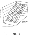
- FIG. 7 is an explanatory view illustrating a correlation between a crank angle or a stroke and an intake pressure.
- Fig. 8 is an explanatory view illustrating a function between an engine load and an intake pressure immediately before an intake stroke.
- Fig. 9 is an explanatory view illustrating a relationship among a fuel pressure, an intake pressure which is an ambient pressure and an injection fuel pressure.
- Fig. 10 is a schematic view illustrating the configuration a motorcycle engine and a control device therefor according to a second embodiment of the invention.
- Fig. 11 is a block diagram illustrating an operational process implemented by the engine control unit shown in Fig. 10.
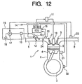
- Fig. 12 is a schematic view illustrating the configuration of a motorcycle engine and a control device therefore according to a third embodiment of the invention.
- Fig. 13 is a block diagram illustrating an operational process implemented by the engine control unit shown in Fig. 12.
- Fig. 1 is a schematic diagram illustrating the configuration of, for example, a motorcycle engine and a control device therefor according to a first embodiment of the invention.
- the engine 1 is a four-cylinder, four-cycle engine and has a cylinder body 2, a crankshaft 3, a piston 4, a combustion chamber 5, an intake pipe 6, an intake valve 7, an exhaust pipe 8, an exhaust valve 9, a spark plug 10, and an ignition coil 11.
- the pump delivery pressure (more accurately, the pump delivery pressure including ambient pressure as a back pressure) is the pressure of the fuel supplied to the injector 13.
- the engine 1 employs an independent suction system, so that the injector 13 is provided in each intake pipe 6 of each cylinder.
- the engine rotational speed calculating part 26 calculates the rotational speed of the crankshaft as an output shaft of the engine as the engine rotational speed based on the rate of change of the crank angle signal with time.
- the crank timing detecting part 27 which has a constitution similar to the stroke judging device disclosed in JA-A-H10-227252, detects the stroke state of each cylinder as shown in Fig. 3, for example, and outputs it as crank timing information. Namely, in a four-cycle engine, the crankshaft and the camshaft are constantly rotated with a prescribed phase difference, so that when crank pulses are read with respect to each 30 degrees rotation of the crank shaft as shown in Fig. 3, the crank pulse "4" represents either an exhaust stroke or a compression stroke. As is well known, during an exhaust stroke, the exhaust valve is closed and the intake valve is opened, so that the intake pipe pressure is high.
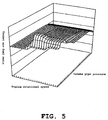
- the target air-fuel ratio calculating part 33 has a three-dimensional map as shown in Fig. 5 for use in calculating the target air-fuel ratio based on the intake pipe pressure signal and the engine rotational speed calculated in the engine rotational speed calculating part 26.
- the three-dimensional map can be organized on paper to some extent.
- the air-fuel ratio is correlated with torque. When the air-fuel ratio is low, namely, when the amount of fuel is large and the amount of air is small, the torque increases but the efficiency decreases. Whereas, when the air-fuel ratio is high, namely, when the amount of fuel is small and the amount of air is large, the torque decreases but the efficiency increases.
- the engine rotational speed is one of parameters indicating running conditions of the engine, and in general, a larger air-fuel ratio is employed at a higher end of the engine rotational speed, whereas a smaller air-fuel ratio is employed at a lower end of the engine rotational speed. This is intended to enhance the response characteristic of the engine torque at the lower end of the engine speed and to enhance the response characteristic of the engine speed at the higher end of the engine speed.
- the target air-fuel ratio has a physical meaning easy to understand and thus can be set to some extent in accordance with required engine output characteristics. It is needless to say that the air-fuel ratio may be tuned in accordance with the output characteristics of an actual engine.
- an intake pressure detected at a predetermined crank timing substantially before the top dead center in a compression stroke was used in setting a target air-fuel ratio using the target air-fuel ratio calculating part 33.
- an intake pressure is used which is detected at a predetermined crank timing before the top dead center in an exhaust stroke, to be specific, immediately before an intake stroke or immediately before the intake valve opens.
- an intake pressure is used which is detected when the fuel injection time is over or is about to be over. Consequently, intake pressures need to be detected at least a plurality of times in the four strokes of intake, compression, expansion and exhaust strokes.
- an acceleration demand by opening the throttle valve or a transition can be detected.
- the ambient pressure calculating part 41 calculates the ambient pressure based on the intake pipe pressure signal and the crank timing information.
- Fig. 7 is a graph of intake pipe pressure versus phase of the crankshaft, namely crank timing information. Each of the curves corresponds to the engine load at the time when the crank angle is -180°. For example, 45 kPa is the minimum engine load and 100 kPa is the maximum engine load.
- an intake stroke is started when tha crank angle is360°. Immediately before the intake stroke, namely when the crank angle is near -360°, the intake pipe pressure is almost stable and is ambient as described later. In an engine without a supercharger, when the intake pipe pressure is stable, it is because the pressure is about ambient.
- (P 1 - P 2 ) in the equation (2) is the injection fuel pressure calculated in the injection fuel pressure calculating part 42.
- P (P 1 - P 2 )
- the fuel injection time can obtained.
- the injection pulse output part 30 calculates a fuel injection initiating timing from crank timing information detected at the crank timing detecting part 27 and outputs to the injector 13 an injection pulse based on the fuel injection time calculated at the fuel injection time calculating part 44.
- the fuel injection amount V required to attain the desired air-fuel ratio and the square root value P 0 1/2 of the reference injection fuel pressure value is set to the preset value and the fuel injection time T is calculated by dividing the preset value by the square root value P 1/2 of the injection fuel pressure value, the fuel injection time required to attain the desired air-fuel ratio can be calculated and set easily and accurately. Additionally, as a result, fuel can be injected with the optimum fuel injection timing, whereby the combustion efficiency can be enhanced.
- the injection fuel pressure is calculated based on the intake pipe pressure as the pressure of the atmosphere into which the fuel is injected, the ambient pressure and the fuel pressure, it is possible to detect the injection fuel pressure accurately and easily. Also, since the ambient pressure is calculated from the pressure in the intake pipe of the engine, there is no need to provide an ambient pressure sensor, making it possible to reduce the number of parts and the costs. Additionally, since the intake pipe pressure immediately before the intake valve of the engine is opened is calculated as the ambient pressure, it is possible to detect the ambient pressure accurately in real time.
- control device for a four-stroke engine can be applied to a single-cylinder engine.
- engine control unit can be replaced by various types of operational circuits instead of the microcomputer.
- a fuel injection time is calculated based on at least one of the plurality of intake pressure values so detected, whereby fuel is injected with an injection initiating timing according to the fuel injection time so calculated, an accurate fuel injection time can be set using an intake pressure detected at a timing which is optimum to calculate the fuel injection time, and as a result, fuel can be injected with the optimum injection initiating timing so as to enhance the combustion efficiency.
- control device for a four-stroke engine of the third aspect of the invention since an intake pressure is detected at least when the fuel injection time so calculated is over or is about to be over, a steady intake pressure resulting substantially while fuel is being injected can be detected, whereby the fuel injection pressure can be detected more accurately and easily.
- the control device for a four-stroke engine of the fifth aspect of the invention since the provision of only the atmospheric pressure is made possible by adopting the configuration in which when the lower limit value of the pump delivery pressure is larger than the control pressure of the regulator, the fuel pressure is made to constitute the control pressure of the regulator, the necessity of the pump delivery pressure sensor is obviated, whereby the number of components involved and production costs can be attempted to be reduced by such an extent.
- control device for a four-stroke engine of the sixth aspect of the invention since an atmospheric pressure is detected from the detected intake pressure, there is no need to provide an atmospheric pressure sensor separately, whereby the number of components involved and production costs can be attempted to be reduced by such an extent.
- control device for a four-stroke engine of the seventh aspect of the invention since at least an intake pressure resulting immediately before the intake valve opens is detected, atmospheric pressures can be detected in real time and accurately by calculating the intake pressure resulting immediately before the intake valve opens as an atmospheric pressure.
Landscapes
- Engineering & Computer Science (AREA)
- Chemical & Material Sciences (AREA)
- Combustion & Propulsion (AREA)
- Mechanical Engineering (AREA)
- General Engineering & Computer Science (AREA)
- Electrical Control Of Air Or Fuel Supplied To Internal-Combustion Engine (AREA)
- Combined Controls Of Internal Combustion Engines (AREA)
Abstract
Description
Claims (8)
- A control device for a four-stroke engine having an intake valve between a combustion chamber and an intake port and having at least one intake control valve for one intake port of the combustion chamber, the control device comprising a pump for pressurizing a fuel in a fuel tank, a regulator opened to an atmospheric pressure for regulating an upper limit value for the fuel pressurized by the pump, a fuel injection device for injecting the fuel regulated an upper limit value thereof by the regulator into the intake port, intake pressure detecting unit for detecting an intake pressure between the intake control valve and the combustion chamber, at least either atmospheric pressure detecting unit for detecting an atmospheric pressure or pump delivery pressure detecting unit for detecting the pressure of the fuel pressurized by the pump, and fuel injection control unit for controlling the fuel injection device based on at least either of an atmospheric pressure detected by the atmospheric pressure detecting unit and a fuel pressure detected by the pump delivery pressure detecting unit and an intake pressure detected by the intake pressure detecting unit, wherein the intake pressure detecting unit detects an intake pressure a plurality of times while the four-stroke engine completes four strokes of intake stroke, compression stroke, expansion stroke and exhaust stoke, and the fuel injection control unit calculates a fuel injection time based on at least one of a plurality of intake pressure values detected by the intake pressure detecting unit so as to inject the fuel with an injection initiating timing according to the fuel injection time so calculated.
- A control device for a four-stroke engine as set forth in Claim 1, wherein the pump and the regulator are disposed within the fuel tank.
- A control device for a four-stroke engine as set forth in Claim 1 or 2, wherein the intake pressure detecting unit detects the intake pressure at least when a fuel injection time calculated by the fuel injection control unit is over or is about to be over.
- A control device for a four-stroke engine as set forth in any of Claims 1 to 3, wherein only the pump delivery pressure detecting unit is provided.
- A control device for a four-stroke engine as set forth in any of Claims 1 to 3, wherein only the atmospheric pressure detecting unit is provided.
- A control device for a four-stroke engine as set forth in any of Claims 1 to 3, or Claim 5, wherein the atmospheric pressure detecting unit detects an atmospheric pressure from an intake pressure detected by the intake pressure detecting unit.
- A control device for a four-stroke engine as set forth in any of Claims 1 to 3, or in Claim 5 or 6, wherein the intake pressure detecting unit detects at least an intake pressure resulting immediately before the intake valve opens.
- A method for controlling a four-stroke engine having an intake valve between a combustion chamber and an intake port and having at least one intake control valve for one intake port of the combustion chamber, the method comprising the steps of pressurizing a fuel in a fuel tank, regulating by a regulator opened to an atmospheric pressure an upper limit value for the fuel pressurized by the pump, injecting the fuel regulated an upper limit value thereof by the regulator into the intake port, detecting an intake pressure between the intake control valve and the combustion chamber, performing at least either the step of detecting an atmospheric pressure or the step of detecting the pressure of the fuel so pressurized, and controlling the fuel injection based on at least either an atmospheric pressure detected through the step of detecting an atmospheric pressure or a fuel pressure detected through the step of detecting a fuel pressure and an intake pressure detected through the step of detecting an intake pressure, wherein in the step of detecting an intake pressure, an intake pressure is detected a plurality of times while the four-stroke engine completes four strokes of intake stroke, compression stroke, expansion stroke and exhaust stoke, and in the step of controlling the fuel injection, a fuel injection time is calculated based on at least one of a plurality of intake pressure values detected through the step of detecting an intake pressure so that the fuel is injected with an injection initiating timing according to the fuel injection time so calculated.
Applications Claiming Priority (3)
| Application Number | Priority Date | Filing Date | Title |
|---|---|---|---|
| JP2001212337 | 2001-07-12 | ||
| JP2001212337 | 2001-07-12 | ||
| PCT/JP2002/007122 WO2003006808A1 (en) | 2001-07-12 | 2002-07-12 | 4-stroke engine control device and control method |
Publications (3)
| Publication Number | Publication Date |
|---|---|
| EP1437498A1 true EP1437498A1 (en) | 2004-07-14 |
| EP1437498A4 EP1437498A4 (en) | 2008-05-14 |
| EP1437498B1 EP1437498B1 (en) | 2010-05-05 |
Family
ID=19047515
Family Applications (1)
| Application Number | Title | Priority Date | Filing Date |
|---|---|---|---|
| EP02746022A Expired - Lifetime EP1437498B1 (en) | 2001-07-12 | 2002-07-12 | 4−STROKE ENGINE CONTROL DEVICE AND CONTROL METHOD |
Country Status (8)
| Country | Link |
|---|---|
| US (1) | US6810855B2 (en) |
| EP (1) | EP1437498B1 (en) |
| JP (1) | JP4050229B2 (en) |
| CN (1) | CN100357581C (en) |
| BR (1) | BR0210355B1 (en) |
| DE (1) | DE60236305D1 (en) |
| TW (1) | TW530117B (en) |
| WO (1) | WO2003006808A1 (en) |
Cited By (2)
| Publication number | Priority date | Publication date | Assignee | Title |
|---|---|---|---|---|
| DE102004041030A1 (en) * | 2004-08-25 | 2006-03-02 | Audi Ag | Method for fuel metering for internal combustion engine with direct fuel injection, especially in the starting phase, entails metering and injecting fuel in dependence upon parameter especially induction pipe pressure |
| WO2007110774A3 (en) * | 2006-03-28 | 2007-12-06 | Toyota Motor Co Ltd | System and method for determining acceleration of an internal combustion engine |
Families Citing this family (20)
| Publication number | Priority date | Publication date | Assignee | Title |
|---|---|---|---|---|
| JP4357881B2 (en) | 2003-06-12 | 2009-11-04 | ヤマハ発動機株式会社 | Small ship |
| JP4135643B2 (en) * | 2004-01-19 | 2008-08-20 | 日産自動車株式会社 | Control device for direct-injection spark-ignition internal combustion engine |
| US7130736B2 (en) * | 2004-02-10 | 2006-10-31 | International Engine Intellectual Property Company, Llc | Engine speed stabilization using fuel rate control |
| JP2006002633A (en) | 2004-06-16 | 2006-01-05 | Yamaha Marine Co Ltd | Water jet propulsion boat |
| JP2006037730A (en) | 2004-07-22 | 2006-02-09 | Yamaha Marine Co Ltd | Intake device for supercharged engine |
| JP2006083713A (en) | 2004-09-14 | 2006-03-30 | Yamaha Marine Co Ltd | Lubricating structure of supercharger |
| DE102004062018B4 (en) * | 2004-12-23 | 2018-10-11 | Robert Bosch Gmbh | Method for operating an internal combustion engine |
| JP2007062432A (en) | 2005-08-29 | 2007-03-15 | Yamaha Marine Co Ltd | Small planing boat |
| JP4614853B2 (en) | 2005-09-26 | 2011-01-19 | ヤマハ発動機株式会社 | Turbocharger mounting structure |
| JP4577348B2 (en) * | 2007-10-24 | 2010-11-10 | 株式会社デンソー | Internal combustion engine control device and internal combustion engine control system |
| US7740000B2 (en) * | 2007-12-14 | 2010-06-22 | Gm Global Technology Operations, Inc. | Method and apparatus for injecting fuel into a compression-ignition engine |
| DE102010063380A1 (en) * | 2010-12-17 | 2012-06-21 | Robert Bosch Gmbh | Method for operating an internal combustion engine |
| DE102011087199A1 (en) * | 2011-05-16 | 2012-11-22 | Robert Bosch Gmbh | Method for operating an internal combustion engine |
| JP5951388B2 (en) * | 2012-07-24 | 2016-07-13 | 日立オートモティブシステムズ株式会社 | Control device for internal combustion engine |
| JP5968771B2 (en) * | 2012-12-07 | 2016-08-10 | 日立オートモティブシステムズ株式会社 | Fuel injection control device for internal combustion engine |
| US9719458B2 (en) * | 2013-09-09 | 2017-08-01 | Nissan Motor Co., Ltd. | Fuel injection control device of engine and fuel injection control method of engine |
| DE102015226461B4 (en) * | 2015-12-22 | 2018-10-04 | Continental Automotive Gmbh | Method for determining the start of injection time and the injection quantity of the fuel in normal operation of an internal combustion engine |
| JP6281581B2 (en) | 2016-01-27 | 2018-02-21 | トヨタ自動車株式会社 | Control device for internal combustion engine |
| JP6281579B2 (en) * | 2016-01-27 | 2018-02-21 | トヨタ自動車株式会社 | Control device for internal combustion engine |
| WO2020097853A1 (en) * | 2018-11-15 | 2020-05-22 | 潍柴动力股份有限公司 | Phase diagnosis method and apparatus |
Family Cites Families (10)
| Publication number | Priority date | Publication date | Assignee | Title |
|---|---|---|---|---|
| JPS4742407B1 (en) | 1970-03-05 | 1972-10-26 | ||
| JPS6098329A (en) | 1983-11-02 | 1985-06-01 | Nissan Motor Co Ltd | Pressure detector of internal-combustion engine |
| JPS6380029A (en) | 1986-09-19 | 1988-04-11 | Mazda Motor Corp | Fuel control unit for engine |
| JPH081143B2 (en) | 1986-09-22 | 1996-01-10 | ヤマハ発動機株式会社 | Fuel injection amount control device |
| JPH0233433A (en) | 1988-07-21 | 1990-02-02 | Fuji Heavy Ind Ltd | Air-fuel ratio control device for engine |
| US5546911A (en) * | 1993-04-20 | 1996-08-20 | Nippondenso Co., Ltd. | Fuel injection control apparatus |
| JPH08326581A (en) | 1995-06-05 | 1996-12-10 | Nissan Motor Co Ltd | Fuel injection amount control device for internal combustion engine |
| JPH09250378A (en) | 1996-03-18 | 1997-09-22 | Fuji Heavy Ind Ltd | Fuel ignition controller for engine |
| DE19646942A1 (en) * | 1996-11-13 | 1998-05-14 | Bayerische Motoren Werke Ag | Fuel injection device for an air-compressing internal combustion engine |
| JP3839119B2 (en) | 1997-02-13 | 2006-11-01 | 本田技研工業株式会社 | 4-cycle engine stroke discrimination device |
-
2002
- 2002-07-12 US US10/471,516 patent/US6810855B2/en not_active Expired - Lifetime
- 2002-07-12 TW TW091115579A patent/TW530117B/en not_active IP Right Cessation
- 2002-07-12 JP JP2003512543A patent/JP4050229B2/en not_active Expired - Lifetime
- 2002-07-12 CN CNB028088719A patent/CN100357581C/en not_active Expired - Lifetime
- 2002-07-12 WO PCT/JP2002/007122 patent/WO2003006808A1/en not_active Ceased
- 2002-07-12 BR BRPI0210355-9A patent/BR0210355B1/en not_active IP Right Cessation
- 2002-07-12 DE DE60236305T patent/DE60236305D1/en not_active Expired - Lifetime
- 2002-07-12 EP EP02746022A patent/EP1437498B1/en not_active Expired - Lifetime
Cited By (4)
| Publication number | Priority date | Publication date | Assignee | Title |
|---|---|---|---|---|
| DE102004041030A1 (en) * | 2004-08-25 | 2006-03-02 | Audi Ag | Method for fuel metering for internal combustion engine with direct fuel injection, especially in the starting phase, entails metering and injecting fuel in dependence upon parameter especially induction pipe pressure |
| DE102004041030B4 (en) * | 2004-08-25 | 2015-12-10 | Audi Ag | Fuel metering for an internal combustion engine with direct fuel injection |
| WO2007110774A3 (en) * | 2006-03-28 | 2007-12-06 | Toyota Motor Co Ltd | System and method for determining acceleration of an internal combustion engine |
| US8256217B2 (en) | 2006-03-28 | 2012-09-04 | Toyota Jidosha Kabushiki Kaisha | System and method for determining acceleration of an internal combustion engine |
Also Published As
| Publication number | Publication date |
|---|---|
| JP4050229B2 (en) | 2008-02-20 |
| EP1437498B1 (en) | 2010-05-05 |
| CN100357581C (en) | 2007-12-26 |
| DE60236305D1 (en) | 2010-06-17 |
| TW530117B (en) | 2003-05-01 |
| BR0210355A (en) | 2004-07-20 |
| JPWO2003006808A1 (en) | 2004-11-04 |
| WO2003006808A1 (en) | 2003-01-23 |
| BR0210355B1 (en) | 2011-04-19 |
| US6810855B2 (en) | 2004-11-02 |
| EP1437498A4 (en) | 2008-05-14 |
| US20040149268A1 (en) | 2004-08-05 |
| CN1505733A (en) | 2004-06-16 |
Similar Documents
| Publication | Publication Date | Title |
|---|---|---|
| US6810855B2 (en) | 4-Stroke engine control device and control method | |
| US7861690B2 (en) | Device and method for controlling internal combustion engine | |
| US7210456B2 (en) | Control device for internal combustion engine and method for determining misfire in internal combustion engine | |
| US7630821B2 (en) | Intake quantity sensing device of internal combustion engine | |
| US5058550A (en) | Method for determining the control values of a multicylinder internal combustion engine and apparatus therefor | |
| US5474045A (en) | Engine control device | |
| JPH0518287A (en) | Fuel injection internal combustion engine | |
| US6983738B2 (en) | Engine control system | |
| EP0924420A2 (en) | Torque controller for internal combustion engine | |
| EP1249593B1 (en) | Control system and method for a multi-cylinder internal combustion engine | |
| US6983646B2 (en) | Atmospheric pressure detection device of four-stroke engine and method of detecting atmospheric pressure | |
| EP1452715B1 (en) | Engine controller | |
| US7448360B2 (en) | Controller of internal combustion engine | |
| US7181336B2 (en) | Control system of internal combustion engine | |
| JP4747977B2 (en) | In-cylinder pressure sensor calibration device | |
| JP2003056378A (en) | Crankshaft rotation sensor | |
| JP2012002620A (en) | Calibration device for in-cylinder pressure sensor | |
| JPH0385341A (en) | Electronic fuel injection control method for two-stroke internal combustion engine with crank chamber preload | |
| JP2002155844A (en) | Engine control device | |
| JP2003013790A (en) | Intake air amount detection device for internal combustion engine |
Legal Events
| Date | Code | Title | Description |
|---|---|---|---|
| PUAI | Public reference made under article 153(3) epc to a published international application that has entered the european phase |
Free format text: ORIGINAL CODE: 0009012 |
|
| 17P | Request for examination filed |
Effective date: 20040212 |
|
| AK | Designated contracting states |
Kind code of ref document: A1 Designated state(s): AT BE BG CH CY CZ DE DK EE ES FI FR GB GR IE IT LI LU MC NL PT SE SK TR |
|
| AX | Request for extension of the european patent |
Extension state: AL LT LV MK RO SI |
|
| A4 | Supplementary search report drawn up and despatched |
Effective date: 20080410 |
|
| 17Q | First examination report despatched |
Effective date: 20090317 |
|
| GRAP | Despatch of communication of intention to grant a patent |
Free format text: ORIGINAL CODE: EPIDOSNIGR1 |
|
| RBV | Designated contracting states (corrected) |
Designated state(s): DE ES FR GB IT |
|
| GRAS | Grant fee paid |
Free format text: ORIGINAL CODE: EPIDOSNIGR3 |
|
| GRAA | (expected) grant |
Free format text: ORIGINAL CODE: 0009210 |
|
| AK | Designated contracting states |
Kind code of ref document: B1 Designated state(s): DE ES FR GB IT |
|
| REG | Reference to a national code |
Ref country code: GB Ref legal event code: FG4D |
|
| REF | Corresponds to: |
Ref document number: 60236305 Country of ref document: DE Date of ref document: 20100617 Kind code of ref document: P |
|
| PG25 | Lapsed in a contracting state [announced via postgrant information from national office to epo] |
Ref country code: ES Free format text: LAPSE BECAUSE OF FAILURE TO SUBMIT A TRANSLATION OF THE DESCRIPTION OR TO PAY THE FEE WITHIN THE PRESCRIBED TIME-LIMIT Effective date: 20100816 |
|
| PLBE | No opposition filed within time limit |
Free format text: ORIGINAL CODE: 0009261 |
|
| STAA | Information on the status of an ep patent application or granted ep patent |
Free format text: STATUS: NO OPPOSITION FILED WITHIN TIME LIMIT |
|
| PG25 | Lapsed in a contracting state [announced via postgrant information from national office to epo] |
Ref country code: IT Free format text: LAPSE BECAUSE OF FAILURE TO SUBMIT A TRANSLATION OF THE DESCRIPTION OR TO PAY THE FEE WITHIN THE PRESCRIBED TIME-LIMIT Effective date: 20100505 |
|
| 26N | No opposition filed |
Effective date: 20110208 |
|
| REG | Reference to a national code |
Ref country code: DE Ref legal event code: R097 Ref document number: 60236305 Country of ref document: DE Effective date: 20110207 |
|
| REG | Reference to a national code |
Ref country code: FR Ref legal event code: PLFP Year of fee payment: 15 |
|
| REG | Reference to a national code |
Ref country code: FR Ref legal event code: PLFP Year of fee payment: 16 |
|
| REG | Reference to a national code |
Ref country code: FR Ref legal event code: PLFP Year of fee payment: 17 |
|
| PGFP | Annual fee paid to national office [announced via postgrant information from national office to epo] |
Ref country code: FR Payment date: 20210727 Year of fee payment: 20 |
|
| PGFP | Annual fee paid to national office [announced via postgrant information from national office to epo] |
Ref country code: GB Payment date: 20210721 Year of fee payment: 20 Ref country code: DE Payment date: 20210721 Year of fee payment: 20 |
|
| REG | Reference to a national code |
Ref country code: DE Ref legal event code: R071 Ref document number: 60236305 Country of ref document: DE |
|
| REG | Reference to a national code |
Ref country code: GB Ref legal event code: PE20 Expiry date: 20220711 |
|
| PG25 | Lapsed in a contracting state [announced via postgrant information from national office to epo] |
Ref country code: GB Free format text: LAPSE BECAUSE OF EXPIRATION OF PROTECTION Effective date: 20220711 |