EP1437482A1 - Opposed pistons engine in only one rotating cylinder - Google Patents
Opposed pistons engine in only one rotating cylinder Download PDFInfo
- Publication number
- EP1437482A1 EP1437482A1 EP20040425003 EP04425003A EP1437482A1 EP 1437482 A1 EP1437482 A1 EP 1437482A1 EP 20040425003 EP20040425003 EP 20040425003 EP 04425003 A EP04425003 A EP 04425003A EP 1437482 A1 EP1437482 A1 EP 1437482A1
- Authority
- EP
- European Patent Office
- Prior art keywords
- cylinder
- holes
- pistons
- stroke
- opposed pistons
- Prior art date
- Legal status (The legal status is an assumption and is not a legal conclusion. Google has not performed a legal analysis and makes no representation as to the accuracy of the status listed.)
- Granted
Links
- 230000033001 locomotion Effects 0.000 claims abstract description 10
- 238000005406 washing Methods 0.000 claims abstract description 9
- 238000002485 combustion reaction Methods 0.000 claims abstract description 8
- 238000010304 firing Methods 0.000 claims abstract description 8
- 230000006835 compression Effects 0.000 claims abstract description 6
- 238000007906 compression Methods 0.000 claims abstract description 6
- 230000001360 synchronised effect Effects 0.000 claims abstract description 6
- 239000007789 gas Substances 0.000 claims description 10
- 239000000446 fuel Substances 0.000 claims description 8
- 238000007789 sealing Methods 0.000 claims description 5
- 239000007788 liquid Substances 0.000 claims description 3
- 230000002860 competitive effect Effects 0.000 description 2
- 238000010276 construction Methods 0.000 description 2
- 239000000463 material Substances 0.000 description 2
- 229910010293 ceramic material Inorganic materials 0.000 description 1
- 238000004891 communication Methods 0.000 description 1
- 238000001816 cooling Methods 0.000 description 1
- 230000002452 interceptive effect Effects 0.000 description 1
- 229910001234 light alloy Inorganic materials 0.000 description 1
- 238000012423 maintenance Methods 0.000 description 1
- 238000000034 method Methods 0.000 description 1
- 239000000203 mixture Substances 0.000 description 1
- 230000001105 regulatory effect Effects 0.000 description 1
- 238000009423 ventilation Methods 0.000 description 1
Images


Classifications
-
- F—MECHANICAL ENGINEERING; LIGHTING; HEATING; WEAPONS; BLASTING
- F01—MACHINES OR ENGINES IN GENERAL; ENGINE PLANTS IN GENERAL; STEAM ENGINES
- F01L—CYCLICALLY OPERATING VALVES FOR MACHINES OR ENGINES
- F01L1/00—Valve-gear or valve arrangements, e.g. lift-valve gear
- F01L1/36—Valve-gear or valve arrangements, e.g. lift-valve gear peculiar to machines or engines of specific type other than four-stroke cycle
-
- F—MECHANICAL ENGINEERING; LIGHTING; HEATING; WEAPONS; BLASTING
- F01—MACHINES OR ENGINES IN GENERAL; ENGINE PLANTS IN GENERAL; STEAM ENGINES
- F01L—CYCLICALLY OPERATING VALVES FOR MACHINES OR ENGINES
- F01L7/00—Rotary or oscillatory slide valve-gear or valve arrangements
- F01L7/02—Rotary or oscillatory slide valve-gear or valve arrangements with cylindrical, sleeve, or part-annularly shaped valves
- F01L7/04—Rotary or oscillatory slide valve-gear or valve arrangements with cylindrical, sleeve, or part-annularly shaped valves surrounding working cylinder or piston
- F01L7/045—Rotary or oscillatory slide valve-gear or valve arrangements with cylindrical, sleeve, or part-annularly shaped valves surrounding working cylinder or piston with two or more valves arranged coaxially
-
- F—MECHANICAL ENGINEERING; LIGHTING; HEATING; WEAPONS; BLASTING
- F02—COMBUSTION ENGINES; HOT-GAS OR COMBUSTION-PRODUCT ENGINE PLANTS
- F02B—INTERNAL-COMBUSTION PISTON ENGINES; COMBUSTION ENGINES IN GENERAL
- F02B75/00—Other engines
- F02B75/28—Engines with two or more pistons reciprocating within same cylinder or within essentially coaxial cylinders
- F02B75/282—Engines with two or more pistons reciprocating within same cylinder or within essentially coaxial cylinders the pistons having equal strokes
-
- F—MECHANICAL ENGINEERING; LIGHTING; HEATING; WEAPONS; BLASTING
- F01—MACHINES OR ENGINES IN GENERAL; ENGINE PLANTS IN GENERAL; STEAM ENGINES
- F01L—CYCLICALLY OPERATING VALVES FOR MACHINES OR ENGINES
- F01L2301/00—Using particular materials
- F01L2301/02—Using ceramic materials
-
- F—MECHANICAL ENGINEERING; LIGHTING; HEATING; WEAPONS; BLASTING
- F02—COMBUSTION ENGINES; HOT-GAS OR COMBUSTION-PRODUCT ENGINE PLANTS
- F02B—INTERNAL-COMBUSTION PISTON ENGINES; COMBUSTION ENGINES IN GENERAL
- F02B75/00—Other engines
- F02B75/02—Engines characterised by their cycles, e.g. six-stroke
- F02B2075/022—Engines characterised by their cycles, e.g. six-stroke having less than six strokes per cycle
- F02B2075/025—Engines characterised by their cycles, e.g. six-stroke having less than six strokes per cycle two
Definitions
- Object of the present invention is a special alternative engine that uses opposed pistons in a single cylinder.
- Scope of the present invention is the realization of an engine that joins in itself characteristics of extreme constructive simplicity, functionality and sturdiness, offering the widest guarantee of reliability and safety in the use, besides facility of maintenance and therefore competitive costs in comparison to the preceding engines.
- the linear opposed movement of the two pistons along the cylinder is synchronized with the opening and closing of the ports.
- a cogwheel that is geared by a drive belt that put in rotation the cylinder (3).
- the whole is devised so that every linear movement of the opposed pistons in the cylinder coincides with a rotation of the same cylinder, so that the holes (5) can fit the holes (6) realized on the external cylinder (7); in such way are realized the various ports of the motor.
- a cycle has two stages (going and back) and five strokes.
- the going stage occur the compression stroke (E), and the internal and external cylinder are in position such as any of the holes (5) and (6), placed on their surface, fits; when the piston has reached the top dead centre, the cylinder, by a following rotation of 10°, fits the central hole (o) respectively of the hole sets (5) and (6) and realizes the inlet port (8) for the spark produced by the plug (9) placed on the external cylinder (7). It is, them, the stroke A of firing of the compressed fuel and therefore the following expansion that begins the back stage of the pistons.
- the cylinder completes a rotation of 155°, so that the couples of the holes with extremity (t) and (t1), ( respectively of the holes of extremity of the hole sets (5) and (6)) fit, forming the exhaust ports (10), from which the gases escape; it is therefore the exhaust stroke B.
- the holes on the internal cylinder fit the holes (11) on the external cylinder, to originate the washing ports (11), from which a powerful air jet discharges the exhaust gases and introduces new air in the engine, realizing the turboventilation stroke C and a further series of advantages that will be pointed out later.
- the pistons reached the bottom dead centre, reverse their stroke and the cylinder, by a rotation of 15°, fits the holes (n) and (n1 ) to realize the inlet ports (12): this is the inlet stroke D.
- the object of the present invention introduces, besides the same advantages described in the patent application NA99A000020, others improvements.
- the rotation of the cylinder allows the reduction of the friction between the pistons and the walls of the same cylinder and, notable thing, the creation of a turbulence, inside the chamber of combustion, that facilitates both the ignition and the discharge of the gases, while the inlet air reaches a cleaner room.
- the introduction in the cylinder of air as clear and cold as possible is very important for a complete combustion, but, for a good mixture, it also needs that this air be turbulent.
- the washing of the cylinder, as well as the turbulence of the comburent is very well realized in the engine conceived according to the present invention.
- the feeding can be allowed both with liquid and gaseous fuel, while the ignition can be made both by plug and by self combustion; in last case the pressure of the fuel is optimized with the diminution of the distance among the pistons at the top dead centre.
- the plug By the rotation of the cylinder, the plug is in communication with the internal side of the cylinder only for the time that the spark strikes and provokes the firing of the fuel; in such way it is the notable advantage that the plug is always cleaned; it is also a smaller wear of it.
- the washing occurs during the exhaust stroke and the air jet is introduced close to the upper side of both the pistons: it strongly contributes to the good result of the same stroke and reduces the deposits on the pistons; it also naturally maintains the temperature of the same pistons at optimal values.
- the washing ports can also have a tangential orientation.
- the inlet ports (11) directs the air close to the pistons, to discharge, better and more quickly, the exhaust gases, dragged up by the same pistons.
- the cold air is collected toward the periphery of the room, so that, after some time, it will be a layer of air on the walls of the cylinder, cooling and maintaining at a constant temperature the walls themselves, without interfering with the temperatures needed to start the engine.
- the engine is very simple in the construction, with an almost perfect balancing of the inertia forces, and therefore absence of vibrations and consequent solicitations, as well as absence of valves, connecting rods, etc.
- the classical strokes of an internal combustion engine, and, more, that of the turboventilation occur in only two stages: in fact, for every complete revolution of the drive shaft, it is a revolution of the cylinder, rotating in only one direction.
- the interposition of bearings between internal and external cylinder allows the rotational motion and the sealing among them.
- the introduction of fuel in the cylinder is regulated by the movement of the pistons, synchronized with the rotation of the cylinder, that opens and closes the inlet and exhaust ports, allowing also a better positioning of the themselves ports, that can be placed or conformed according to the various engines built for specific applications.
- the engine has the necessary characteristics of resistance to the stress, which the elements have to support, and, therefore, it can offer the widest guarantees of reliability and safety in the use. Actually, it can be realized with the maximum precision using elements and materials easily available, e.g. ceramic material or light alloys, also in critical parts, like the sealing rings, the sliding element of the piston and the sealing among internal and external cylinder; therefore, it can be said that it is competitive from an economic point of view.
Landscapes
- Engineering & Computer Science (AREA)
- Mechanical Engineering (AREA)
- General Engineering & Computer Science (AREA)
- Chemical & Material Sciences (AREA)
- Combustion & Propulsion (AREA)
- Cylinder Crankcases Of Internal Combustion Engines (AREA)
- Valve Device For Special Equipments (AREA)
- Reciprocating Pumps (AREA)
- Ink Jet (AREA)
- Compressor (AREA)
- Compressors, Vaccum Pumps And Other Relevant Systems (AREA)
- Hydraulic Motors (AREA)
Abstract
Description
- Object of the present invention is a special alternative engine that uses opposed pistons in a single cylinder.
- This engine is well known in the technique and it has been object of a first Italian patent N. 01270326, by the same applicant, in association with others. Further improvements have been described in a following patent application NA99A000020 wherein, instead of the first patent, the pistons having remarkable difference that the top surface is generally plane and the upper side diagonally cut, to create an elliptic surface perfectly plane; it is, moreover, a mechanism that allows the rotation of the pistons while they move in the cylinder. Although this invention gives remarkable advantages, however it allows many complications in the construction.
- Scope of the present invention is the realization of an engine that joins in itself characteristics of extreme constructive simplicity, functionality and sturdiness, offering the widest guarantee of reliability and safety in the use, besides facility of maintenance and therefore competitive costs in comparison to the preceding engines.
- Other scope of the present invention is the realization of an engine that allows advantages in flexibility of applications and use, from the small motorcycle to the ship, from the chain saw to the tractor, from the compressor to the airplane; can be realized also compressors for liquids and gases.
- The tasks and the scopes above mentioned, and others that will be better pointed out later, are reached by an alternative engine with opposed pistons having the upper sides joined in a single chamber of combustion, characterized in that the pistons move rectilinearly, synchronized with the internal cylinder, which has rotational movement and is equipped with holes along its surface, to originate, by an external cylinder also provided with holes, the classical inlet, compression, firing and expansion-exhaust strokes, and anymore the washings stroke, what they happen in only two strokes.
- These and others characteristics, as well as advantages, will result more clear from the following description and from the enclosed drawings and illustrations, furnished to only indicative and not limitative purpose, in which:
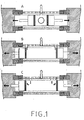
- the fig. 1 and 2 schematically show, in a general sectional view, the various strokes of the motor;
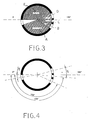
- the fig. 3 and 4 schematically show, in a sectional view, the position of the various holes on the rotating cylinder and the angular strokes, in degree, beginning from the top dead centre;
- the fig. 5 schematically shows, in a lateral sectional view, the position of both the internal and external cylinder during the firing stroke A;
- the fig. 6 shows, in a plan view, the alignment of the corresponding holes among the internal cylinder al) and the external cylinder f) to originate the port for the sparking plug;
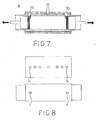
- the fig. 7 schematically shows, in a lateral sectional view, the position of both the internal and external cylinder during the expansion-exhaust stroke B;
- the fig. 8 shows, in a plan view, the alignment of the corresponding holes among the internal cylinder b1) and the external cylinder f) to originate the exhaust port;
- the fig. 9 schematically shows, in a lateral sectional view, the position of both the internal and external cylinder during the turboventilation-exhaust stroke C;
- the fig. 10 shows, in a plan view, the alignment of the corresponding holes among the internal cylinder c1) and the external cylinder f) to originate the ventilation port;
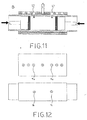
- the fig. 11 schematically shows, in a lateral sectional view, the position of both the internal and external cylinder during the inlet stroke D;
- the fig. 12 shows, in a plan view, the alignment of the corresponding holes among the internal cylinder d1) and the external cylinder f) to originate the inlet port;
- the fig. 13 schematically shows, in a lateral sectional view, the position of both the internal and external cylinder during the compression stroke E;
- the fig. 14 shows, in a plan view, the alignment of the corresponding holes among the internal cylinder e1) and the external cylinder f): in this case, there is no alignments among the holes, and therefore there is no ports.
-
- In relation to the drawings, with (1) are indicated the opposed pistons, cylindrically shaped, provided, along their circumference, of sealing rings (2); the pistons move linearly along the internal cylinder (3), having a constant circular section until a slot, from which the same cylinder has a smaller diameter (4). On the surface of the internal cylinder (3) there are the holes (5), opportunely placed, which, in a favourite way of realization, are seven in number, symmetrically and diagonally set on three different planes and one place to the center, to fit further holes (6), also seven in number, linearly placed on a single axle, on the external cylinder (7), coaxial to the cylinder (3) and having circular section.
- The whole of the holes (5) and (6), placed on both the internal and external cylinder, realizes the entry and exit ports of the engine, according to the present invention. The linear opposed movement of the two pistons along the cylinder is synchronized with the opening and closing of the ports. In fact, on the extremity (4) of the cylinder (3) is fitted a cogwheel that is geared by a drive belt that put in rotation the cylinder (3). The whole is devised so that every linear movement of the opposed pistons in the cylinder coincides with a rotation of the same cylinder, so that the holes (5) can fit the holes (6) realized on the external cylinder (7); in such way are realized the various ports of the motor.
- In this engine, a cycle has two stages (going and back) and five strokes. In the going stage occur the compression stroke (E), and the internal and external cylinder are in position such as any of the holes (5) and (6), placed on their surface, fits; when the piston has reached the top dead centre, the cylinder, by a following rotation of 10°, fits the central hole (o) respectively of the hole sets (5) and (6) and realizes the inlet port (8) for the spark produced by the plug (9) placed on the external cylinder (7). It is, them, the stroke A of firing of the compressed fuel and therefore the following expansion that begins the back stage of the pistons. The cylinder completes a rotation of 155°, so that the couples of the holes with extremity (t) and (t1), ( respectively of the holes of extremity of the hole sets (5) and (6)) fit, forming the exhaust ports (10), from which the gases escape; it is therefore the exhaust stroke B. After a rotation of 25°, the holes on the internal cylinder fit the holes (11) on the external cylinder, to originate the washing ports (11), from which a powerful air jet discharges the exhaust gases and introduces new air in the engine, realizing the turboventilation stroke C and a further series of advantages that will be pointed out later. From this point the pistons, reached the bottom dead centre, reverse their stroke and the cylinder, by a rotation of 15°, fits the holes (n) and (n1 ) to realize the inlet ports (12): this is the inlet stroke D.
- The object of the present invention introduces, besides the same advantages described in the patent application NA99A000020, others improvements. In fact, it is easy to observe that the rotation of the cylinder allows the reduction of the friction between the pistons and the walls of the same cylinder and, notable thing, the creation of a turbulence, inside the chamber of combustion, that facilitates both the ignition and the discharge of the gases, while the inlet air reaches a cleaner room. It is known that the introduction in the cylinder of air as clear and cold as possible is very important for a complete combustion, but, for a good mixture, it also needs that this air be turbulent. The washing of the cylinder, as well as the turbulence of the comburent, is very well realized in the engine conceived according to the present invention.
- The feeding can be allowed both with liquid and gaseous fuel, while the ignition can be made both by plug and by self combustion; in last case the pressure of the fuel is optimized with the diminution of the distance among the pistons at the top dead centre.
- By the rotation of the cylinder, the plug is in communication with the internal side of the cylinder only for the time that the spark strikes and provokes the firing of the fuel; in such way it is the notable advantage that the plug is always cleaned; it is also a smaller wear of it.
- The washing occurs during the exhaust stroke and the air jet is introduced close to the upper side of both the pistons: it strongly contributes to the good result of the same stroke and reduces the deposits on the pistons; it also naturally maintains the temperature of the same pistons at optimal values. To get turbulent motions, the washing ports can also have a tangential orientation. As evident from the attached drawings, the inlet ports (11) directs the air close to the pistons, to discharge, better and more quickly, the exhaust gases, dragged up by the same pistons. Because of the rotation of the cylinder, the cold air is collected toward the periphery of the room, so that, after some time, it will be a layer of air on the walls of the cylinder, cooling and maintaining at a constant temperature the walls themselves, without interfering with the temperatures needed to start the engine. The engine is very simple in the construction, with an almost perfect balancing of the inertia forces, and therefore absence of vibrations and consequent solicitations, as well as absence of valves, connecting rods, etc. The classical strokes of an internal combustion engine, and, more, that of the turboventilation, occur in only two stages: in fact, for every complete revolution of the drive shaft, it is a revolution of the cylinder, rotating in only one direction. The interposition of bearings between internal and external cylinder allows the rotational motion and the sealing among them.
- The introduction of fuel in the cylinder is regulated by the movement of the pistons, synchronized with the rotation of the cylinder, that opens and closes the inlet and exhaust ports, allowing also a better positioning of the themselves ports, that can be placed or conformed according to the various engines built for specific applications.
- Other notable advantage, in comparison to preceding engines, is the lightness, the simplicity of operation as well as the lowering of the temperature of the exhaust gases, because of the turboventilation.
- Although it has not been represented in the attached figures, other advantage of the present engine is that it can also do without the clutch in the gear. In fact, on every side of the cylinder, it can be realized two power drives, and therefore four drive shaft, connectable to four pulleys of different diameter, to have the various gear ratios.
- The engine, according to the present invention, has the necessary characteristics of resistance to the stress, which the elements have to support, and, therefore, it can offer the widest guarantees of reliability and safety in the use. Actually, it can be realized with the maximum precision using elements and materials easily available, e.g. ceramic material or light alloys, also in critical parts, like the sealing rings, the sliding element of the piston and the sealing among internal and external cylinder; therefore, it can be said that it is competitive from an economic point of view.
- As previously described and illustrated, it is clear that the invention reaches the scope. All the parts can technically be replaced by other equivalent elements; all the materials employees, as well as the dimensions and the shape, can be adjusted according to the application.
Claims (10)
- Alternative engine with opposed pistons having the upper sides joined in a single chamber of combustion, characterized in that the pistons move rectilinearly, synchronized with the internal cylinder, which has rotational movement and is equipped with holes along its surface, to originate, by an external cylinder also provided with holes, the classical inlet, compression, firing and expansion-exhaust strokes, and anymore the washings stroke, what they are happened in only two strokes.
- Alternative engine with opposed pistons, as claimed in claim 1, characterized in that the internal cylinder (3) has constant circular section until a slot, from which the same cylinder has a smaller diameter (4); on its surface they are the holes (5), seven in number and symmetrically and diagonally set on three different planes with One placed centrally.
- Alternative engine with opposed pistons, as claimed in claim 1, characterized in that on the external cylinder (7), with circular section and coaxial to the internal cylinder (3), the holes (6), seven in number, are placed linearly, on a single axle.
- Alternative engine with opposed pistons, as claimed in claims 1, 2 and 3, characterized in that the holes (5), realized on the internal cylinder, can fit the holes (6), realized on the external cylinder (7), so that to realize the various entry and exit ports of the motor.
- Alternative engine with opposed pistons, as claimed in claims 1, 2, 3 and 4, characterized in that the linear movement of the two opposed pistons along the cylinder is synchronized with the opening and closing of the ports: in fact, on the extremity (4) of the cylinder (3) is fitted a cogwheel, that is geared by a drive belt that puts in rotation the cylinder (3).
- Alternative engine with opposed pistons, as claimed in claims 1, 2, 3, 4 and 5, characterized by a cycle having five strokes: during the compression stroke E, the internal and external cylinders are in position such as any of the holes (5) and (6), placed on their surface, fits; when the piston has reached the top dead centre, the cylinder, by a following rotation of 10°, fits the central hole (o) respectively of the hole sets (5) and (6) and realizes the inlet port (8) of the spark, produced by the plug (9), placed on the external cylinder (7), it is the stroke A of firing of the compressed fuel and therefore the following expansion; the cylinder completes a rotation of 155°, so that the couples of the extremity holes (t) and (t1), (respectively of the hole sets (5) and (6)), fit, forming the exhaust ports (10), from which the gases escape, it is the exhaust stroke B; after a rotation of others 25°, the holes (1) on the internal cylinder fit the holes (11) on the external cylinder, to originate the washing ports (11), from which a powerful air jet discharges the exhaust gases and introduces new air in the engine, realizing the turboventilation stroke C; from this point the pistons, reached the bottom dead centre, reverse their stroke and the cylinder, by a rotation of others 15°, fits the holes (n) and (n1) to realize the inlet ports (12), this is the inlet stroke D.
- Alternative engine with opposed pistons, as claimed in claims 1, 2, 3, 4, 5 and 6, characterized in that the feeding can be allowed both with liquid and gaseous fuel, while the ignition can be made both by plug and by self combustion; in last case the pressure of the fuel is optimized with the diminution of the distance among the pistons at the top dead centre.
- Alternative engine with opposed pistons, as claimed in claims 1, 2, 3, 4, 5, 6 and 7, characterized in that the washing occurs during the exhaust stroke and the air jet is introduced close to the upper side of both the pistons, where are the exhaust gases that are dragged up by the pistons themselves, while the plug is exposed to the exhaust gases only during the firing stroke.
- Alternative engine with opposed pistons, as claimed in claims 1, 2, 3, 4, 5, 6 and 7 characterized in that the interposition of bearings between internal and external cylinder allows the rotational motion and the sealing among them.
- Alternative engine with opposed pistons, as claimed in preceding claims, characterized by the fact that it can do without the clutch in the gear.
Applications Claiming Priority (2)
| Application Number | Priority Date | Filing Date | Title |
|---|---|---|---|
| ITSA20030002 | 2003-01-07 | ||
| IT2003SA000001A ITSA20030001A1 (en) | 2003-01-07 | 2003-01-07 | INNOVATION IN THE PISTON MOTOR OPPOSED IN A SINGLE ROTATING CYLINDER. |
Publications (2)
| Publication Number | Publication Date |
|---|---|
| EP1437482A1 true EP1437482A1 (en) | 2004-07-14 |
| EP1437482B1 EP1437482B1 (en) | 2006-05-17 |
Family
ID=27621002
Family Applications (1)
| Application Number | Title | Priority Date | Filing Date |
|---|---|---|---|
| EP04425003A Expired - Lifetime EP1437482B1 (en) | 2003-01-07 | 2004-01-07 | Opposed pistons engine in only one rotating cylinder |
Country Status (4)
| Country | Link |
|---|---|
| EP (1) | EP1437482B1 (en) |
| AT (1) | ATE326616T1 (en) |
| DE (1) | DE602004000865T2 (en) |
| IT (1) | ITSA20030001A1 (en) |
Cited By (1)
| Publication number | Priority date | Publication date | Assignee | Title |
|---|---|---|---|---|
| WO2010151238A1 (en) * | 2009-05-12 | 2010-12-29 | Oescan Erg | Rotary valve system-for internal combustion engines |
Citations (4)
| Publication number | Priority date | Publication date | Assignee | Title |
|---|---|---|---|---|
| DE865237C (en) * | 1944-03-21 | 1953-02-12 | Otto Sierenberg | Control for a two-stroke internal combustion engine with direct current flushing |
| GB2129488A (en) * | 1982-09-30 | 1984-05-16 | James Milner | Rotary cylinder valve internal combustion engine |
| US5351657A (en) * | 1992-09-28 | 1994-10-04 | Buck Erik S | Modular power unit |
| EP1355053A1 (en) * | 2002-04-19 | 2003-10-22 | Herbert Dr. h.c. Hüttlin | Rotary piston engine |
-
2003
- 2003-01-07 IT IT2003SA000001A patent/ITSA20030001A1/en unknown
-
2004
- 2004-01-07 EP EP04425003A patent/EP1437482B1/en not_active Expired - Lifetime
- 2004-01-07 DE DE602004000865T patent/DE602004000865T2/en not_active Expired - Lifetime
- 2004-01-07 AT AT04425003T patent/ATE326616T1/en not_active IP Right Cessation
Patent Citations (4)
| Publication number | Priority date | Publication date | Assignee | Title |
|---|---|---|---|---|
| DE865237C (en) * | 1944-03-21 | 1953-02-12 | Otto Sierenberg | Control for a two-stroke internal combustion engine with direct current flushing |
| GB2129488A (en) * | 1982-09-30 | 1984-05-16 | James Milner | Rotary cylinder valve internal combustion engine |
| US5351657A (en) * | 1992-09-28 | 1994-10-04 | Buck Erik S | Modular power unit |
| EP1355053A1 (en) * | 2002-04-19 | 2003-10-22 | Herbert Dr. h.c. Hüttlin | Rotary piston engine |
Cited By (1)
| Publication number | Priority date | Publication date | Assignee | Title |
|---|---|---|---|---|
| WO2010151238A1 (en) * | 2009-05-12 | 2010-12-29 | Oescan Erg | Rotary valve system-for internal combustion engines |
Also Published As
| Publication number | Publication date |
|---|---|
| DE602004000865T2 (en) | 2007-03-01 |
| DE602004000865D1 (en) | 2006-06-22 |
| ATE326616T1 (en) | 2006-06-15 |
| ITSA20030001A1 (en) | 2003-04-07 |
| EP1437482B1 (en) | 2006-05-17 |
Similar Documents
| Publication | Publication Date | Title |
|---|---|---|
| KR101711778B1 (en) | Rotary piston machine and controlling gear arrangement | |
| US10006360B2 (en) | Rotary directional pressure engine | |
| US10094218B1 (en) | Continuous motion revolving piston engine | |
| JPH01237301A (en) | Power transmission device | |
| EP0421033A1 (en) | Continuous combustion heat engine | |
| EP1437482A1 (en) | Opposed pistons engine in only one rotating cylinder | |
| WO2023104225A1 (en) | Rotary combustion engine | |
| TWI589769B (en) | Circulating piston engine | |
| EP0734486B1 (en) | Rotary engine | |
| JPS6033979B2 (en) | Internal combustion turbine and combustion gas distribution mechanism | |
| GB2145152A (en) | Rotary valve i.c. engine | |
| RU2374454C2 (en) | Design of piston machine and method of designing its working chamber for thermodynamic cycle | |
| CN101842554B (en) | piston compressor | |
| RU2477377C2 (en) | Internal combustion engine: five-stroke rotary engine with one central rotary gate shared by separate working medium compression and expansion sections, and isolated invariable-volume combustion chambers | |
| RU2613753C1 (en) | Internal combustion engine | |
| WO2017146599A1 (en) | A mechanism of the shift from sliding to rotation, and from rotation to sliding, with rotating pistons, and a set of such mechanisms | |
| US6883489B2 (en) | Rotational engine | |
| RU2444635C2 (en) | Rotary engine | |
| RU2267612C2 (en) | Rotary piston internal combustion engine | |
| RU2278287C2 (en) | Two-rotor internal combustion engine | |
| CA1141671A (en) | Rotary internal combustion engine | |
| US1136488A (en) | Gas-driven air-compressor. | |
| KR101796315B1 (en) | Rotary Piston Engine | |
| RU2316659C1 (en) | Rotary bladed internal combustion engine | |
| CN101285419B (en) | A triangular rotary opposing cylinder device and its realization method |
Legal Events
| Date | Code | Title | Description |
|---|---|---|---|
| PUAI | Public reference made under article 153(3) epc to a published international application that has entered the european phase |
Free format text: ORIGINAL CODE: 0009012 |
|
| AK | Designated contracting states |
Kind code of ref document: A1 Designated state(s): AT BE BG CH CY CZ DE DK EE ES FI FR GB GR HU IE IT LI LU MC NL PT RO SE SI SK TR |
|
| AX | Request for extension of the european patent |
Extension state: AL LT LV MK |
|
| AKX | Designation fees paid | ||
| 17P | Request for examination filed |
Effective date: 20050118 |
|
| RBV | Designated contracting states (corrected) |
Designated state(s): AT BE BG CH CY CZ DE DK EE ES FI FR GB GR HU IE IT LI LU MC NL PT RO SE SI SK TR |
|
| REG | Reference to a national code |
Ref country code: DE Ref legal event code: 8566 |
|
| 17Q | First examination report despatched |
Effective date: 20050512 |
|
| GRAP | Despatch of communication of intention to grant a patent |
Free format text: ORIGINAL CODE: EPIDOSNIGR1 |
|
| GRAS | Grant fee paid |
Free format text: ORIGINAL CODE: EPIDOSNIGR3 |
|
| GRAA | (expected) grant |
Free format text: ORIGINAL CODE: 0009210 |
|
| AK | Designated contracting states |
Kind code of ref document: B1 Designated state(s): AT BE BG CH CY CZ DE DK EE ES FI FR GB GR HU IE IT LI LU MC NL PT RO SE SI SK TR |
|
| PG25 | Lapsed in a contracting state [announced via postgrant information from national office to epo] |
Ref country code: CH Free format text: LAPSE BECAUSE OF FAILURE TO SUBMIT A TRANSLATION OF THE DESCRIPTION OR TO PAY THE FEE WITHIN THE PRESCRIBED TIME-LIMIT Effective date: 20060517 Ref country code: FI Free format text: LAPSE BECAUSE OF FAILURE TO SUBMIT A TRANSLATION OF THE DESCRIPTION OR TO PAY THE FEE WITHIN THE PRESCRIBED TIME-LIMIT Effective date: 20060517 Ref country code: CZ Free format text: LAPSE BECAUSE OF FAILURE TO SUBMIT A TRANSLATION OF THE DESCRIPTION OR TO PAY THE FEE WITHIN THE PRESCRIBED TIME-LIMIT Effective date: 20060517 Ref country code: AT Free format text: LAPSE BECAUSE OF FAILURE TO SUBMIT A TRANSLATION OF THE DESCRIPTION OR TO PAY THE FEE WITHIN THE PRESCRIBED TIME-LIMIT Effective date: 20060517 Ref country code: LI Free format text: LAPSE BECAUSE OF FAILURE TO SUBMIT A TRANSLATION OF THE DESCRIPTION OR TO PAY THE FEE WITHIN THE PRESCRIBED TIME-LIMIT Effective date: 20060517 Ref country code: BE Free format text: LAPSE BECAUSE OF FAILURE TO SUBMIT A TRANSLATION OF THE DESCRIPTION OR TO PAY THE FEE WITHIN THE PRESCRIBED TIME-LIMIT Effective date: 20060517 Ref country code: NL Free format text: LAPSE BECAUSE OF FAILURE TO SUBMIT A TRANSLATION OF THE DESCRIPTION OR TO PAY THE FEE WITHIN THE PRESCRIBED TIME-LIMIT Effective date: 20060517 Ref country code: RO Free format text: LAPSE BECAUSE OF FAILURE TO SUBMIT A TRANSLATION OF THE DESCRIPTION OR TO PAY THE FEE WITHIN THE PRESCRIBED TIME-LIMIT Effective date: 20060517 Ref country code: SK Free format text: LAPSE BECAUSE OF FAILURE TO SUBMIT A TRANSLATION OF THE DESCRIPTION OR TO PAY THE FEE WITHIN THE PRESCRIBED TIME-LIMIT Effective date: 20060517 Ref country code: SI Free format text: LAPSE BECAUSE OF FAILURE TO SUBMIT A TRANSLATION OF THE DESCRIPTION OR TO PAY THE FEE WITHIN THE PRESCRIBED TIME-LIMIT Effective date: 20060517 Ref country code: IT Free format text: LAPSE BECAUSE OF FAILURE TO SUBMIT A TRANSLATION OF THE DESCRIPTION OR TO PAY THE FEE WITHIN THE PRESCRIBED TIME-LIMIT;WARNING: LAPSES OF ITALIAN PATENTS WITH EFFECTIVE DATE BEFORE 2007 MAY HAVE OCCURRED AT ANY TIME BEFORE 2007. THE CORRECT EFFECTIVE DATE MAY BE DIFFERENT FROM THE ONE RECORDED. Effective date: 20060517 |
|
| REG | Reference to a national code |
Ref country code: GB Ref legal event code: FG4D |
|
| REG | Reference to a national code |
Ref country code: CH Ref legal event code: EP |
|
| REG | Reference to a national code |
Ref country code: IE Ref legal event code: FG4D |
|
| REF | Corresponds to: |
Ref document number: 602004000865 Country of ref document: DE Date of ref document: 20060622 Kind code of ref document: P |
|
| PG25 | Lapsed in a contracting state [announced via postgrant information from national office to epo] |
Ref country code: SE Free format text: LAPSE BECAUSE OF FAILURE TO SUBMIT A TRANSLATION OF THE DESCRIPTION OR TO PAY THE FEE WITHIN THE PRESCRIBED TIME-LIMIT Effective date: 20060817 Ref country code: DK Free format text: LAPSE BECAUSE OF FAILURE TO SUBMIT A TRANSLATION OF THE DESCRIPTION OR TO PAY THE FEE WITHIN THE PRESCRIBED TIME-LIMIT Effective date: 20060817 |
|
| PG25 | Lapsed in a contracting state [announced via postgrant information from national office to epo] |
Ref country code: ES Free format text: LAPSE BECAUSE OF FAILURE TO SUBMIT A TRANSLATION OF THE DESCRIPTION OR TO PAY THE FEE WITHIN THE PRESCRIBED TIME-LIMIT Effective date: 20060828 |
|
| PG25 | Lapsed in a contracting state [announced via postgrant information from national office to epo] |
Ref country code: PT Free format text: LAPSE BECAUSE OF FAILURE TO SUBMIT A TRANSLATION OF THE DESCRIPTION OR TO PAY THE FEE WITHIN THE PRESCRIBED TIME-LIMIT Effective date: 20061017 |
|
| NLV1 | Nl: lapsed or annulled due to failure to fulfill the requirements of art. 29p and 29m of the patents act | ||
| REG | Reference to a national code |
Ref country code: CH Ref legal event code: PL |
|
| PG25 | Lapsed in a contracting state [announced via postgrant information from national office to epo] |
Ref country code: IE Free format text: LAPSE BECAUSE OF NON-PAYMENT OF DUE FEES Effective date: 20070108 |
|
| ET | Fr: translation filed | ||
| PG25 | Lapsed in a contracting state [announced via postgrant information from national office to epo] |
Ref country code: MC Free format text: LAPSE BECAUSE OF NON-PAYMENT OF DUE FEES Effective date: 20070131 |
|
| PLBE | No opposition filed within time limit |
Free format text: ORIGINAL CODE: 0009261 |
|
| STAA | Information on the status of an ep patent application or granted ep patent |
Free format text: STATUS: NO OPPOSITION FILED WITHIN TIME LIMIT |
|
| 26N | No opposition filed |
Effective date: 20070220 |
|
| REG | Reference to a national code |
Ref country code: FR Ref legal event code: ST Effective date: 20070930 |
|
| REG | Reference to a national code |
Ref country code: FR Ref legal event code: RN |
|
| REG | Reference to a national code |
Ref country code: FR Ref legal event code: FC |
|
| PG25 | Lapsed in a contracting state [announced via postgrant information from national office to epo] |
Ref country code: GR Free format text: LAPSE BECAUSE OF FAILURE TO SUBMIT A TRANSLATION OF THE DESCRIPTION OR TO PAY THE FEE WITHIN THE PRESCRIBED TIME-LIMIT Effective date: 20060818 Ref country code: FR Free format text: LAPSE BECAUSE OF NON-PAYMENT OF DUE FEES Effective date: 20070131 |
|
| PG25 | Lapsed in a contracting state [announced via postgrant information from national office to epo] |
Ref country code: BG Free format text: LAPSE BECAUSE OF FAILURE TO SUBMIT A TRANSLATION OF THE DESCRIPTION OR TO PAY THE FEE WITHIN THE PRESCRIBED TIME-LIMIT Effective date: 20060817 |
|
| PG25 | Lapsed in a contracting state [announced via postgrant information from national office to epo] |
Ref country code: EE Free format text: LAPSE BECAUSE OF FAILURE TO SUBMIT A TRANSLATION OF THE DESCRIPTION OR TO PAY THE FEE WITHIN THE PRESCRIBED TIME-LIMIT Effective date: 20060517 |
|
| PG25 | Lapsed in a contracting state [announced via postgrant information from national office to epo] |
Ref country code: CY Free format text: LAPSE BECAUSE OF FAILURE TO SUBMIT A TRANSLATION OF THE DESCRIPTION OR TO PAY THE FEE WITHIN THE PRESCRIBED TIME-LIMIT Effective date: 20060517 Ref country code: LU Free format text: LAPSE BECAUSE OF NON-PAYMENT OF DUE FEES Effective date: 20070107 |
|
| PG25 | Lapsed in a contracting state [announced via postgrant information from national office to epo] |
Ref country code: TR Free format text: LAPSE BECAUSE OF FAILURE TO SUBMIT A TRANSLATION OF THE DESCRIPTION OR TO PAY THE FEE WITHIN THE PRESCRIBED TIME-LIMIT Effective date: 20060517 Ref country code: HU Free format text: LAPSE BECAUSE OF FAILURE TO SUBMIT A TRANSLATION OF THE DESCRIPTION OR TO PAY THE FEE WITHIN THE PRESCRIBED TIME-LIMIT Effective date: 20061118 |
|
| PGFP | Annual fee paid to national office [announced via postgrant information from national office to epo] |
Ref country code: FR Payment date: 20081229 Year of fee payment: 6 |
|
| PGFP | Annual fee paid to national office [announced via postgrant information from national office to epo] |
Ref country code: IT Payment date: 20110131 Year of fee payment: 8 Ref country code: DE Payment date: 20110201 Year of fee payment: 8 |
|
| PGFP | Annual fee paid to national office [announced via postgrant information from national office to epo] |
Ref country code: GB Payment date: 20110201 Year of fee payment: 8 |
|
| GBPC | Gb: european patent ceased through non-payment of renewal fee |
Effective date: 20120107 |
|
| PG25 | Lapsed in a contracting state [announced via postgrant information from national office to epo] |
Ref country code: GB Free format text: LAPSE BECAUSE OF NON-PAYMENT OF DUE FEES Effective date: 20120107 Ref country code: DE Free format text: LAPSE BECAUSE OF NON-PAYMENT OF DUE FEES Effective date: 20120801 |
|
| REG | Reference to a national code |
Ref country code: DE Ref legal event code: R119 Ref document number: 602004000865 Country of ref document: DE Effective date: 20120801 |
|
| PG25 | Lapsed in a contracting state [announced via postgrant information from national office to epo] |
Ref country code: IT Free format text: LAPSE BECAUSE OF NON-PAYMENT OF DUE FEES Effective date: 20120107 |