EP1437194A2 - Process of removing a ceramic coating deposit in a surface hole of a component - Google Patents
Process of removing a ceramic coating deposit in a surface hole of a component Download PDFInfo
- Publication number
- EP1437194A2 EP1437194A2 EP20040250086 EP04250086A EP1437194A2 EP 1437194 A2 EP1437194 A2 EP 1437194A2 EP 20040250086 EP20040250086 EP 20040250086 EP 04250086 A EP04250086 A EP 04250086A EP 1437194 A2 EP1437194 A2 EP 1437194A2
- Authority
- EP
- European Patent Office
- Prior art keywords
- hole
- ceramic
- component
- laser beam
- deposit
- Prior art date
- Legal status (The legal status is an assumption and is not a legal conclusion. Google has not performed a legal analysis and makes no representation as to the accuracy of the status listed.)
- Granted
Links
Images
Classifications
-
- B—PERFORMING OPERATIONS; TRANSPORTING
- B23—MACHINE TOOLS; METAL-WORKING NOT OTHERWISE PROVIDED FOR
- B23K—SOLDERING OR UNSOLDERING; WELDING; CLADDING OR PLATING BY SOLDERING OR WELDING; CUTTING BY APPLYING HEAT LOCALLY, e.g. FLAME CUTTING; WORKING BY LASER BEAM
- B23K26/00—Working by laser beam, e.g. welding, cutting or boring
- B23K26/02—Positioning or observing the workpiece, e.g. with respect to the point of impact; Aligning, aiming or focusing the laser beam
- B23K26/06—Shaping the laser beam, e.g. by masks or multi-focusing
- B23K26/062—Shaping the laser beam, e.g. by masks or multi-focusing by direct control of the laser beam
- B23K26/0622—Shaping the laser beam, e.g. by masks or multi-focusing by direct control of the laser beam by shaping pulses
-
- B—PERFORMING OPERATIONS; TRANSPORTING
- B23—MACHINE TOOLS; METAL-WORKING NOT OTHERWISE PROVIDED FOR
- B23K—SOLDERING OR UNSOLDERING; WELDING; CLADDING OR PLATING BY SOLDERING OR WELDING; CUTTING BY APPLYING HEAT LOCALLY, e.g. FLAME CUTTING; WORKING BY LASER BEAM
- B23K26/00—Working by laser beam, e.g. welding, cutting or boring
- B23K26/36—Removing material
- B23K26/38—Removing material by boring or cutting
- B23K26/382—Removing material by boring or cutting by boring
-
- B—PERFORMING OPERATIONS; TRANSPORTING
- B23—MACHINE TOOLS; METAL-WORKING NOT OTHERWISE PROVIDED FOR
- B23K—SOLDERING OR UNSOLDERING; WELDING; CLADDING OR PLATING BY SOLDERING OR WELDING; CUTTING BY APPLYING HEAT LOCALLY, e.g. FLAME CUTTING; WORKING BY LASER BEAM
- B23K26/00—Working by laser beam, e.g. welding, cutting or boring
- B23K26/36—Removing material
- B23K26/38—Removing material by boring or cutting
- B23K26/382—Removing material by boring or cutting by boring
- B23K26/389—Removing material by boring or cutting by boring of fluid openings, e.g. nozzles, jets
-
- B—PERFORMING OPERATIONS; TRANSPORTING
- B23—MACHINE TOOLS; METAL-WORKING NOT OTHERWISE PROVIDED FOR
- B23K—SOLDERING OR UNSOLDERING; WELDING; CLADDING OR PLATING BY SOLDERING OR WELDING; CUTTING BY APPLYING HEAT LOCALLY, e.g. FLAME CUTTING; WORKING BY LASER BEAM
- B23K26/00—Working by laser beam, e.g. welding, cutting or boring
- B23K26/36—Removing material
- B23K26/40—Removing material taking account of the properties of the material involved
-
- B—PERFORMING OPERATIONS; TRANSPORTING
- B23—MACHINE TOOLS; METAL-WORKING NOT OTHERWISE PROVIDED FOR
- B23K—SOLDERING OR UNSOLDERING; WELDING; CLADDING OR PLATING BY SOLDERING OR WELDING; CUTTING BY APPLYING HEAT LOCALLY, e.g. FLAME CUTTING; WORKING BY LASER BEAM
- B23K2101/00—Articles made by soldering, welding or cutting
- B23K2101/001—Turbines
-
- B—PERFORMING OPERATIONS; TRANSPORTING
- B23—MACHINE TOOLS; METAL-WORKING NOT OTHERWISE PROVIDED FOR
- B23K—SOLDERING OR UNSOLDERING; WELDING; CLADDING OR PLATING BY SOLDERING OR WELDING; CUTTING BY APPLYING HEAT LOCALLY, e.g. FLAME CUTTING; WORKING BY LASER BEAM
- B23K2101/00—Articles made by soldering, welding or cutting
- B23K2101/34—Coated articles ; Surface treated articles
-
- B—PERFORMING OPERATIONS; TRANSPORTING
- B23—MACHINE TOOLS; METAL-WORKING NOT OTHERWISE PROVIDED FOR
- B23K—SOLDERING OR UNSOLDERING; WELDING; CLADDING OR PLATING BY SOLDERING OR WELDING; CUTTING BY APPLYING HEAT LOCALLY, e.g. FLAME CUTTING; WORKING BY LASER BEAM
- B23K2103/00—Materials to be soldered, welded or cut
- B23K2103/50—Inorganic materials other than metals or composite materials
-
- B—PERFORMING OPERATIONS; TRANSPORTING
- B23—MACHINE TOOLS; METAL-WORKING NOT OTHERWISE PROVIDED FOR
- B23K—SOLDERING OR UNSOLDERING; WELDING; CLADDING OR PLATING BY SOLDERING OR WELDING; CUTTING BY APPLYING HEAT LOCALLY, e.g. FLAME CUTTING; WORKING BY LASER BEAM
- B23K2103/00—Materials to be soldered, welded or cut
- B23K2103/50—Inorganic materials other than metals or composite materials
- B23K2103/52—Ceramics
-
- B—PERFORMING OPERATIONS; TRANSPORTING
- B23—MACHINE TOOLS; METAL-WORKING NOT OTHERWISE PROVIDED FOR
- B23P—METAL-WORKING NOT OTHERWISE PROVIDED FOR; COMBINED OPERATIONS; UNIVERSAL MACHINE TOOLS
- B23P2700/00—Indexing scheme relating to the articles being treated, e.g. manufactured, repaired, assembled, connected or other operations covered in the subgroups
- B23P2700/06—Cooling passages of turbine components, e.g. unblocking or preventing blocking of cooling passages of turbine components
Definitions
- the present invention generally relates to ceramic coatings deposited on components with surface holes that are required to remain open after the coating process. More particularly, this invention is directed to a method of removing ceramic coating deposits from surface holes using a laser drilling technique having parameters that reduce the incidence of delamination and cracking of the ceramic coating surrounding the surface hole.
- TBC thermal barrier coatings
- Metal oxides such as zirconia (ZrO 2 ) partially or fully stabilized by yttria (Y 2 O 3 ), magnesia (MgO) or other oxides, have been widely employed as the material for the thermal-insulating ceramic layer.
- the ceramic layer is typically deposited by air plasma spraying (APS), low pressure plasma spraying (LPPS), or a physical vapor deposition (PVD) technique, such as electron beam physical vapor deposition (EBPVD).
- Bond coats are typically formed of an oxidation-resistant diffusion coating such as a diffusion aluminide or platinum aluminide, or an oxidation-resistant overlay coating such as MCrAlY (where M is iron, cobalt and/or nickel).
- TBC systems provide significant thermal protection to the underlying component substrate
- internal cooling of components such as combustor liners and turbine blades (buckets) and nozzles (vanes) is often necessary, and may be employed in combination with or in lieu of a TBC.
- Air-cooled components of a gas turbine engine typically require that the cooling air flow is discharged through carefully configured cooling holes that distribute a cooling film over the component surface to increase the effectiveness of the cooling flow.
- Cooling holes are typically formed by such conventional drilling techniques as electrical-discharge machining (EDM) and laser drilling, or with complex advanced casting practices that yield castings with dimensionally correct openings.
- EDM electrical-discharge machining
- laser drilling or with complex advanced casting practices that yield castings with dimensionally correct openings.
- EDM cannot be used to form cooling holes in a component having an existing ceramic TBC since ceramic is electrically nonconducting.
- cooling holes are often machined by EDM or laser drilling after deposition of the bond coat but prior to application of the TBC.
- the presence of TBC deposits in the cooling holes of an air-cooled component can detrimentally affect the service life of the component as a result of the TBC altering the shape and reducing the size of the cooling hole openings.
- TBC's deposited by plasma spraying APS and LPPS
- a significant amount of ceramic can be deposited in the cooling holes when depositing a sufficiently thick TBC to thermally insulate hot section components.
- the obstruction of cooling holes with TBC not only occurs with new manufactured air-cooled components, but also when refurbishing a TBC on a component returned from the field.
- Emer does not disclose modifying a pulsed IR laser beam to avoid the delamination and cracking of the TBC that has been reported by others in the prior art. Instead, Emer reports that the precise actual location of a cooling hole is required to effectively redrill a coated hole without damage to the component. For this purpose, Emer uses a CNC program to originally install the cooling holes and then preliminarily locate the holes for redrilling, but then requires a machine vision system to more precisely identify the actual location of the cooling holes on the component surface.
- a process of removing ceramic deposits from a surface hole in a component a particular example being portions of a ceramic coating material deposited on a surface of an air-cooled gas turbine engine component.
- the process is particularly effective in removing a TBC material deposited in a cooling hole of a component as a result of coating a surface of the component with the TBC material, in which the deposit is removed from the cooling hole without damaging the cooling hole or the TBC surrounding the cooling hole on the coated surface of the component.
- the process of this invention makes use of a pulsed Nd:YAG laser operated with parameters that enable the laser beam to remove ceramic material from a cooling hole without delaminating, cracking or otherwise damaging the TBC surrounding the cooling hole, and without any special equipment or efforts to precisely identify the hole location. Instead, the present invention is able to make use of the same fixturing and programming used to originally install the cooling holes.
- the pulsed Nd:YAG laser is operated in a free-running mode at relatively lower power levels and higher frequencies that conventionally used. These parameters include a pulse frequency of about 2 to about 20 Hz and pulse widths of about 0.25 to about 6.0 milliseconds, with preferred parameters being dependent on the hole diameter.
- the invention makes use of a laser beam whose diameter is smaller than the cooling hole being redrilled, and the laser is equipped with breakthrough detection so that the beam is not projected onto the hole walls, with the result that the hole entrance after laser drilling is defined by remaining ceramic deposits surrounding the hole and is therefore smaller than the original diameter of the hole at the component surface.
- the process of this invention is able to remove ceramic from cooling holes with diameters of less than 0.020 inch (about 0.5 mm) and even below 0.010 inch (about 0.25 mm), and even where the TBC surrounding the hole has a thickness in excess of 0.020 inch (about 0.5 mm).
- a process for removing a ceramic deposit from a surface hole in accordance with this invention includes positioning an Nd:YAG laser generator so that a laser beam generated by the generator is directed at the original programmed location of the hole used during installation of the hole.
- a pulsed laser beam having a diameter less than the as-installed hole is then directed at the programmed location of the hole to remove the ceramic deposit.
- the pulsed laser beam has a pulse width and pulse frequency that enables the ceramic deposit to be removed from the hole without substantial delamination or cracking of the ceramic coating surrounding the hole. Because special equipment and efforts are not required to precisely identify the hole location, the process of this invention can be easily implemented while also enabling cooling holes to be redrilled with significantly lower manufacturing costs due to reduced cycle time.
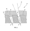
- Figure 1 represents a cross-sectional view of cooling holes before and after removal of a ceramic deposit in accordance with this invention.
- Figure 1 represents a cross-sectional view through cooling holes 12 that intersect a surface 16 of an air-cooled component 10 of a gas turbine engine.
- the component 10 may be formed of an iron, nickel or cobalt-base superalloy, though other high temperature materials could foreseeably be used.
- heat is transferred from the component 10 by forcing bleed air through the cooling holes 12 in a direction indicated by the arrows in Figure 1.
- the amount of heat transferred to the surface 16 of the component 10 can be further reduced by forming the cooling holes 12 to be disposed at an acute angle relative to the surface 16 of the component 10, so that air discharged from the cooling hole 12 flows over the surface 16 of the component 12.
- Suitable techniques for forming the holes 12 include EDM or laser drilling, though it is foreseeable that the holes 12 could be formed by such other methods as casting or abrasive water jet machining.
- the cooling holes 12 are carefully located and configured to maximize their efficiency.
- the equipment used to form the holes 12 is preferably controlled by a CNC (computer numerical control) machine that operates in accordance with a program written to locate multiple points on the surface 16 where the cooling holes 12 are desired. These spatial measurements are stored in machine coordinates on a PC, and are therefore accessible for accurately locating cooling holes on a second component fixtured in essentially an identical manner.
- the CNC machine is also preferably programed to automatically set up the desired drilling parameters, such as power, pulse width and frequency if the holes 12 are formed by laser drilling, so that minimal operator intervention is required to perform set-up for each component to be processed.
- the use of CNC equipment to drill cooling holes in gas turbine engine components is well known to those skilled in the art, and therefore will not be discussed in any further detail.
- the component 10 is represented in Figure 1 as having a ceramic coating (i.e., TBC) 20 deposited on its surface 16.
- the coating 20 is bonded to the surface 16 with a metallic bond coat 18, which with the ceramic coating 20 defines a thermal barrier coating (TBC) system.
- TBC thermal barrier coating
- Particularly suitable bond coat materials include diffusion aluminide and/or MCrAlY overlay coatings, while a suitable TBC material is zirconia partially stabilized with yttria (yttria-stabilized zirconia, or YSZ), though zirconia fully stabilized with yttria could be used, as well as zirconia stabilized by other oxides, such as magnesia (MgO), calcia (CaO), ceria (CeO 2 ) or scandia (Sc 2 O 3 ).
- the cooling holes 12 are shown as containing a ceramic deposit 22 adhered to their walls as a result of the process by which the ceramic coating 20 was deposited.
- Figure 1 schematically represents the coating 20 as being deposited by plasma spraying, such as air plasma spraying (APS) or low pressure plasma spraying (LPPS), though other deposition processes could be used.
- plasma spraying such as air plasma spraying (APS) or low pressure plasma spraying (LPPS)
- the component 10 can be positioned on a conventional turntable, and a suitable spray apparatus located adjacent the turntable is used to apply the coating material as the component 10 is rotated.
- the component 10 is preferably heat treated in a vacuum to reduce residual stresses in the ceramic coating 20.
- Suitable heat treatment parameters include a treatment temperature of about 1025°C to about 1125°C maintained for a duration of about two to about eight hours.
- Figure 1 shows the coating 20 as being much thicker than the diameter of the cooling holes 20, which increases the likelihood that the ceramic deposits 22 will completely block the cooling holes 12, as represented by the cooling hole 12 on the lefthand side of Figure 1.
- the cooling holes 12 may have diameters of less than about 0.030 inch (about 0.75 mm), such as about 0.020 inch (about 0.50 mm) or less, and possibly less than 0.010 inch (about 0.25 mm), while it may be desirable for the coating 20 to be deposited to thicknesses of greater than 0.020 inch (about 0.50 mm), such as 0.030 inch (about 0.75 mm) or more.
- the ceramic deposits 22 must be removed from the cooling holes 12 to reestablish the desired diameter and shape of the holes 12, as represented by the cooling hole 12 on the righthand side of Figure 1.
- the ceramic deposits 22 within the cooling holes 12 are removed with an Nd:YAG laser generator without damaging the component 10 or the coating 20 immediately surrounding the cooling holes 12.
- an Nd:YAG laser employed by the invention is operated in a free running mode to produce a relatively low power, high frequency pulsed laser beam 24 in the IR spectrum. Preferred parameters are dependent in part on the diameter of the cooling holes 12.
- the pulsed laser beam 24 can have a pulse width of about 0.25 to about 6.0 milliseconds and a pulse frequency of about 2 to about 20 Hz, more preferably a pulse width of about 0.55 to about 0.75 milliseconds and a pulse frequency of about 13 to about 17 Hz, with a pulse width of about 0.65 milliseconds and a pulse frequency of about 15 Hz being most preferred.
- the pulsed laser beam 24 should have a pulse width of about 0.4 to about 1.0 milliseconds and a pulse frequency of about 6 to about 16 Hz, with preferable and preferred pulse widths and pulse frequencies being the same as those for holes 12 smaller than 0.010 inch.
- the diameter of the laser beam 24 must be sufficiently smaller than the holes 12, and the Nd:YAG laser must be equipped with breakthrough detection of a type known in the art to interrupt the laser beam 24, so that the beam 24 is not projected onto the walls of the holes 12.
- the laser beam 24 can be seen as tapered (via a focusing lens), and the entrance to the hole 12 defined by the remaining ceramic deposit 22 is smaller than the original diameter of the hole 12 at the component surface 16.
- the original drilled diameter of the holes 12 at the component surface 16 is larger than the diameter desired for the holes 12, which after the laser redrilling process of the invention is established by a surface opening defined by the remaining ceramic deposits 22 surrounding the holes 12.
- the component 10 is preferably placed back on the same fixture (or an identical fixture) used to hold the component 10 when the cooling holes 12 were originally installed.
- the data used by the CNC program to locate the holes 12 can then be used to relocate the cooling holes 12 on the component 10.
- the pulsed laser beam 24 is then directed at the entrance of the hole 12, along a trajectory coaxial with the cooling hole 12. Drilling continues until the laser beam 24 breaks through the ceramic deposit 22, at which point the beam 24 is interrupted to limit thermal effects.
- cooling holes were first laser drilled and then redrilled in a stage 1 HPT duct segment of a gas turbine engine following TBC deposition. Prior to installing the cooling holes, an overlay bond coat was deposited on the surface of the component by air plasma spraying. An Nd:YAG laser operated with conventional high power, low frequency parameters was then used to drill approximately 0.022 inch (about 0.56 mm) diameter holes in the component. Laser drilling was performed with a CNC machine programmed to locate the cooling holes in the component surface while the component was fixtured. The component then underwent an aluminide coating cycle (about 1875°F (about 1024°C) for about five hours).
- a YSZ TBC was then deposited by air plasma spraying to a thickness of about 0.035 inch (about 0.9 mm), with a result that the cooling holes were completely blocked by the TBC.
- the component was returned to the laser drilling fixture, and the programmed hole location data was employed to control an Nd:YAG laser. Based only on the programmed hole locations, the Nd:YAG laser was positioned relative to the component and then operated to sequentially project a laser beam into each cooling hole for the purpose of removing the ceramic deposit within the hole.
- the Nd:YAG laser was operated in a free running mode to generate a pulsed IR laser beam having a pulse width of about 0.65 millisecond and a pulse frequency of about 15 Hz.
- the beam evaporated the ceramic deposit from each cooling hole until interrupted by a breakthrough detection system.
- the resulting openings formed by the beam through the ceramic was about 0.018 inch (about 0.46 mm) in diameter.
- Metallographic examination of the component showed that no significant delamination or cracking of the TBC had occurred around the cooling holes.
Landscapes
- Physics & Mathematics (AREA)
- Optics & Photonics (AREA)
- Engineering & Computer Science (AREA)
- Plasma & Fusion (AREA)
- Mechanical Engineering (AREA)
- Laser Beam Processing (AREA)
- Turbine Rotor Nozzle Sealing (AREA)
Abstract
Description
- The present invention generally relates to ceramic coatings deposited on components with surface holes that are required to remain open after the coating process. More particularly, this invention is directed to a method of removing ceramic coating deposits from surface holes using a laser drilling technique having parameters that reduce the incidence of delamination and cracking of the ceramic coating surrounding the surface hole.
- Components located in certain sections of gas turbine engines, such as the turbine, combustor and augmentor, are often thermally insulated with a ceramic layer in order to reduce their service temperatures, which allows the engine to operate more efficiently at higher temperatures. These coatings, often referred to as thermal barrier coatings (TBC), must have low thermal conductivity, strongly adhere to the article, and remain adherent throughout many heating and cooling cycles. Coating systems capable of satisfying these requirements typically include a metallic bond coat that adheres the thermal-insulating ceramic layer to the component, forming what may be termed a TBC system. Metal oxides, such as zirconia (ZrO2) partially or fully stabilized by yttria (Y2O3), magnesia (MgO) or other oxides, have been widely employed as the material for the thermal-insulating ceramic layer. The ceramic layer is typically deposited by air plasma spraying (APS), low pressure plasma spraying (LPPS), or a physical vapor deposition (PVD) technique, such as electron beam physical vapor deposition (EBPVD). Bond coats are typically formed of an oxidation-resistant diffusion coating such as a diffusion aluminide or platinum aluminide, or an oxidation-resistant overlay coating such as MCrAlY (where M is iron, cobalt and/or nickel).
- While TBC systems provide significant thermal protection to the underlying component substrate, internal cooling of components such as combustor liners and turbine blades (buckets) and nozzles (vanes) is often necessary, and may be employed in combination with or in lieu of a TBC. Air-cooled components of a gas turbine engine typically require that the cooling air flow is discharged through carefully configured cooling holes that distribute a cooling film over the component surface to increase the effectiveness of the cooling flow. Cooling holes are typically formed by such conventional drilling techniques as electrical-discharge machining (EDM) and laser drilling, or with complex advanced casting practices that yield castings with dimensionally correct openings. However, EDM cannot be used to form cooling holes in a component having an existing ceramic TBC since ceramic is electrically nonconducting. While laser drilling techniques are capable of forming cooling holes in a TBC-coated component, the brittle ceramic TBC surrounding the cooling hole is prone to delamination and cracking of the TBC at the interface between the TBC and the underlying metallic bond coat. Accordingly, cooling holes are often machined by EDM or laser drilling after deposition of the bond coat but prior to application of the TBC. However, the presence of TBC deposits in the cooling holes of an air-cooled component can detrimentally affect the service life of the component as a result of the TBC altering the shape and reducing the size of the cooling hole openings. Particularly for TBC's deposited by plasma spraying (APS and LPPS), a significant amount of ceramic can be deposited in the cooling holes when depositing a sufficiently thick TBC to thermally insulate hot section components. The obstruction of cooling holes with TBC not only occurs with new manufactured air-cooled components, but also when refurbishing a TBC on a component returned from the field.
- From the above, it can be seen that manufacturing and refurbishing an air-cooled component protected by a TBC is complicated by the requirement that the cooling holes remain appropriately sized and shaped. Typical solutions are to limit the thickness of the TBC applied or, more preferably, perform a final operation to remove ceramic from the cooling holes in order to reestablish the desired size and shape of the openings. Various techniques have been proposed for this purpose. One approach is to employ a waterjet treatment, a notable example of which is disclosed in commonly-assigned U.S. Patent Application Serial No. 10/086,266 to Farmer et al. As cooling hole diameters decrease, generally below 0.020 inch (about 0.5 mm) and particularly below 0.010 inch (about 0.25 mm), removal of ceramic becomes more difficult with a waterjet, especially for TBC thicknesses in excess of 0.020 inch (about 0.5 mm). As noted above, while conventional laser drilling techniques tend to delaminate and crack the brittle ceramic TBC surrounding a cooling hole, various laser drilling techniques have been proposed that are reported to minimize TBC damage. Commonly-assigned U.S. Patent No. 5,216,808 to Martus et al. reports the propensity for Nd:YAG (neodymium-doped yttrium-aluminum-garnet) lasers to damage the ceramic coating surrounding a cooling hole as a result of these lasers generating beams in the infrared (IR) spectrum that thermally remove the ceramic. To avoid this problem, Martus et al. use an Excimer laser, which generates a beam in the ultraviolet spectrum, to athermally ablate a ceramic coating from a cooling hole. Commonly-assigned U.S. Patent No. 6,172,331 to Chen further recognizes the propensity for pulsed Nd:YAG lasers to cause TBC cracking, and as a solution utilizes a pulsed Nd:YAG laser in combination with a harmonic generator to reduce the laser beam wavelength to about 532 nanometers, which is shorter than IR wavelengths. Finally, U.S. Patent No. 6,380,512 to Emer also discloses the use of a pulsed Nd:YAG laser to remove ceramic from a cooling hole. Emer does not alter the wavelength of the Nd:YAG laser beam used to remove the ceramic, but instead uses the laser beam at its standard IR wavelength of 1060 nm. Emer does not disclose modifying a pulsed IR laser beam to avoid the delamination and cracking of the TBC that has been reported by others in the prior art. Instead, Emer reports that the precise actual location of a cooling hole is required to effectively redrill a coated hole without damage to the component. For this purpose, Emer uses a CNC program to originally install the cooling holes and then preliminarily locate the holes for redrilling, but then requires a machine vision system to more precisely identify the actual location of the cooling holes on the component surface.
- According to the present invention, there is provided a process of removing ceramic deposits from a surface hole in a component, a particular example being portions of a ceramic coating material deposited on a surface of an air-cooled gas turbine engine component. The process is particularly effective in removing a TBC material deposited in a cooling hole of a component as a result of coating a surface of the component with the TBC material, in which the deposit is removed from the cooling hole without damaging the cooling hole or the TBC surrounding the cooling hole on the coated surface of the component.
- The process of this invention makes use of a pulsed Nd:YAG laser operated with parameters that enable the laser beam to remove ceramic material from a cooling hole without delaminating, cracking or otherwise damaging the TBC surrounding the cooling hole, and without any special equipment or efforts to precisely identify the hole location. Instead, the present invention is able to make use of the same fixturing and programming used to originally install the cooling holes. To enable the use of more relaxed positioning requirements, the pulsed Nd:YAG laser is operated in a free-running mode at relatively lower power levels and higher frequencies that conventionally used. These parameters include a pulse frequency of about 2 to about 20 Hz and pulse widths of about 0.25 to about 6.0 milliseconds, with preferred parameters being dependent on the hole diameter. In addition, the invention makes use of a laser beam whose diameter is smaller than the cooling hole being redrilled, and the laser is equipped with breakthrough detection so that the beam is not projected onto the hole walls, with the result that the hole entrance after laser drilling is defined by remaining ceramic deposits surrounding the hole and is therefore smaller than the original diameter of the hole at the component surface. The process of this invention is able to remove ceramic from cooling holes with diameters of less than 0.020 inch (about 0.5 mm) and even below 0.010 inch (about 0.25 mm), and even where the TBC surrounding the hole has a thickness in excess of 0.020 inch (about 0.5 mm).
- In view of the above, a process for removing a ceramic deposit from a surface hole in accordance with this invention includes positioning an Nd:YAG laser generator so that a laser beam generated by the generator is directed at the original programmed location of the hole used during installation of the hole. A pulsed laser beam having a diameter less than the as-installed hole is then directed at the programmed location of the hole to remove the ceramic deposit. The pulsed laser beam has a pulse width and pulse frequency that enables the ceramic deposit to be removed from the hole without substantial delamination or cracking of the ceramic coating surrounding the hole. Because special equipment and efforts are not required to precisely identify the hole location, the process of this invention can be easily implemented while also enabling cooling holes to be redrilled with significantly lower manufacturing costs due to reduced cycle time.
- The invention will now be described in greater detail, by way of example, with reference to the drawings, in which:-
- Figure 1 represents a cross-sectional view of cooling holes before and after removal of a ceramic deposit in accordance with this invention.
- Figure 1 represents a cross-sectional view through
cooling holes 12 that intersect asurface 16 of an air-cooledcomponent 10 of a gas turbine engine. Thecomponent 10 may be formed of an iron, nickel or cobalt-base superalloy, though other high temperature materials could foreseeably be used. As known in the art, to minimize the service temperature of thecomponent 10, heat is transferred from thecomponent 10 by forcing bleed air through thecooling holes 12 in a direction indicated by the arrows in Figure 1. The amount of heat transferred to thesurface 16 of thecomponent 10 can be further reduced by forming thecooling holes 12 to be disposed at an acute angle relative to thesurface 16 of thecomponent 10, so that air discharged from thecooling hole 12 flows over thesurface 16 of thecomponent 12. Suitable techniques for forming theholes 12 include EDM or laser drilling, though it is foreseeable that theholes 12 could be formed by such other methods as casting or abrasive water jet machining. - To promote heat transfer from the
component 10, thecooling holes 12 are carefully located and configured to maximize their efficiency. For this purpose, the equipment used to form theholes 12 is preferably controlled by a CNC (computer numerical control) machine that operates in accordance with a program written to locate multiple points on thesurface 16 where thecooling holes 12 are desired. These spatial measurements are stored in machine coordinates on a PC, and are therefore accessible for accurately locating cooling holes on a second component fixtured in essentially an identical manner. The CNC machine is also preferably programed to automatically set up the desired drilling parameters, such as power, pulse width and frequency if theholes 12 are formed by laser drilling, so that minimal operator intervention is required to perform set-up for each component to be processed. The use of CNC equipment to drill cooling holes in gas turbine engine components is well known to those skilled in the art, and therefore will not be discussed in any further detail. - The
component 10 is represented in Figure 1 as having a ceramic coating (i.e., TBC) 20 deposited on itssurface 16. Thecoating 20 is bonded to thesurface 16 with ametallic bond coat 18, which with theceramic coating 20 defines a thermal barrier coating (TBC) system. Particularly suitable bond coat materials include diffusion aluminide and/or MCrAlY overlay coatings, while a suitable TBC material is zirconia partially stabilized with yttria (yttria-stabilized zirconia, or YSZ), though zirconia fully stabilized with yttria could be used, as well as zirconia stabilized by other oxides, such as magnesia (MgO), calcia (CaO), ceria (CeO2) or scandia (Sc2O3). Thecooling holes 12 are shown as containing aceramic deposit 22 adhered to their walls as a result of the process by which theceramic coating 20 was deposited. Figure 1 schematically represents thecoating 20 as being deposited by plasma spraying, such as air plasma spraying (APS) or low pressure plasma spraying (LPPS), though other deposition processes could be used. To apply thecoating 20, thecomponent 10 can be positioned on a conventional turntable, and a suitable spray apparatus located adjacent the turntable is used to apply the coating material as thecomponent 10 is rotated. Following the coating operation, thecomponent 10 is preferably heat treated in a vacuum to reduce residual stresses in theceramic coating 20. Suitable heat treatment parameters include a treatment temperature of about 1025°C to about 1125°C maintained for a duration of about two to about eight hours. - Figure 1 shows the
coating 20 as being much thicker than the diameter of thecooling holes 20, which increases the likelihood that theceramic deposits 22 will completely block thecooling holes 12, as represented by thecooling hole 12 on the lefthand side of Figure 1. For example, thecooling holes 12 may have diameters of less than about 0.030 inch (about 0.75 mm), such as about 0.020 inch (about 0.50 mm) or less, and possibly less than 0.010 inch (about 0.25 mm), while it may be desirable for thecoating 20 to be deposited to thicknesses of greater than 0.020 inch (about 0.50 mm), such as 0.030 inch (about 0.75 mm) or more. - Whether the
component 10 is newly manufactured or has been returned from the field, because thecooling holes 12 were formed first, theceramic deposits 22 must be removed from thecooling holes 12 to reestablish the desired diameter and shape of theholes 12, as represented by thecooling hole 12 on the righthand side of Figure 1. According to the invention, theceramic deposits 22 within the cooling holes 12 are removed with an Nd:YAG laser generator without damaging thecomponent 10 or thecoating 20 immediately surrounding the cooling holes 12. For this purpose, an Nd:YAG laser employed by the invention is operated in a free running mode to produce a relatively low power, high frequency pulsedlaser beam 24 in the IR spectrum. Preferred parameters are dependent in part on the diameter of the cooling holes 12. If theholes 12 have diameters of less than 0.010 inch (about 0.25 mm), thepulsed laser beam 24 can have a pulse width of about 0.25 to about 6.0 milliseconds and a pulse frequency of about 2 to about 20 Hz, more preferably a pulse width of about 0.55 to about 0.75 milliseconds and a pulse frequency of about 13 to about 17 Hz, with a pulse width of about 0.65 milliseconds and a pulse frequency of about 15 Hz being most preferred. If theholes 12 have diameters of greater than 0.010 inch (about 0.25 mm), thepulsed laser beam 24 should have a pulse width of about 0.4 to about 1.0 milliseconds and a pulse frequency of about 6 to about 16 Hz, with preferable and preferred pulse widths and pulse frequencies being the same as those forholes 12 smaller than 0.010 inch. For these important parameters to fully succeed, the diameter of thelaser beam 24 must be sufficiently smaller than theholes 12, and the Nd:YAG laser must be equipped with breakthrough detection of a type known in the art to interrupt thelaser beam 24, so that thebeam 24 is not projected onto the walls of theholes 12. In Figure 1, thelaser beam 24 can be seen as tapered (via a focusing lens), and the entrance to thehole 12 defined by the remainingceramic deposit 22 is smaller than the original diameter of thehole 12 at thecomponent surface 16. As such, the original drilled diameter of theholes 12 at thecomponent surface 16 is larger than the diameter desired for theholes 12, which after the laser redrilling process of the invention is established by a surface opening defined by the remainingceramic deposits 22 surrounding theholes 12. - In the process of removing the
ceramic deposits 22 from the cooling holes 12, thecomponent 10 is preferably placed back on the same fixture (or an identical fixture) used to hold thecomponent 10 when the cooling holes 12 were originally installed. The data used by the CNC program to locate theholes 12 can then be used to relocate the cooling holes 12 on thecomponent 10. As represented in Figure 1, thepulsed laser beam 24 is then directed at the entrance of thehole 12, along a trajectory coaxial with thecooling hole 12. Drilling continues until thelaser beam 24 breaks through theceramic deposit 22, at which point thebeam 24 is interrupted to limit thermal effects. - In an investigation leading to this invention, cooling holes were first laser drilled and then redrilled in a stage 1 HPT duct segment of a gas turbine engine following TBC deposition. Prior to installing the cooling holes, an overlay bond coat was deposited on the surface of the component by air plasma spraying. An Nd:YAG laser operated with conventional high power, low frequency parameters was then used to drill approximately 0.022 inch (about 0.56 mm) diameter holes in the component. Laser drilling was performed with a CNC machine programmed to locate the cooling holes in the component surface while the component was fixtured. The component then underwent an aluminide coating cycle (about 1875°F (about 1024°C) for about five hours). A YSZ TBC was then deposited by air plasma spraying to a thickness of about 0.035 inch (about 0.9 mm), with a result that the cooling holes were completely blocked by the TBC. After heat treating the component at about 1975°F (about 1080°C) for about four hours in a vacuum, the component was returned to the laser drilling fixture, and the programmed hole location data was employed to control an Nd:YAG laser. Based only on the programmed hole locations, the Nd:YAG laser was positioned relative to the component and then operated to sequentially project a laser beam into each cooling hole for the purpose of removing the ceramic deposit within the hole. The Nd:YAG laser was operated in a free running mode to generate a pulsed IR laser beam having a pulse width of about 0.65 millisecond and a pulse frequency of about 15 Hz. The beam evaporated the ceramic deposit from each cooling hole until interrupted by a breakthrough detection system. The resulting openings formed by the beam through the ceramic was about 0.018 inch (about 0.46 mm) in diameter. Metallographic examination of the component showed that no significant delamination or cracking of the TBC had occurred around the cooling holes.
- For the sake of good order, various aspects of the invention are set out in the following clauses:-
- 1. A process of removing a ceramic deposit (22) from a surface hole (12)
of a component (10) having a ceramic coating (20) on a surface (16) thereof,
the process comprising the steps of:
- positioning an Nd:YAG laser generator so that a laser beam (24) generated by the generator is directed at the programmed location of the hole (12) used during installation of the hole (12); and then
- directing a pulsed laser beam (24) at the programmed location of the hole (12) to remove the ceramic deposit (22) from the hole (12), the pulsed laser beam (24) having a diameter less than the hole (12) at the surface (16) of the component (10), a pulse width of about 0.25 to about 6.0 milliseconds, and a pulse frequency of about 2 to about 20 Hz, wherein some of the ceramic deposit (22) is removed from the hole (12) and a residual portion of the ceramic deposit (22) remains surrounding the hole (12) to define a surface opening without substantial delamination or cracking of the ceramic coating (20) surrounding the hole (12).
- 2. A process according to clause 1, wherein the ceramic coating (20) has a thickness of greater than 0.5 mm.
- 3. A process according to clause 1, wherein the ceramic coating (20) has a thickness of greater than 0.75 mm.
- 4. A process according to clause 1, wherein the hole (12) has a diameter of greater than 0.25 mm and the pulsed laser beam (24) has a pulse width of about 0.4 to about 1.0 milliseconds and a pulse frequency of about 6 to about 16 Hz.
- 5. A process according to clause 1, wherein the hole (12) has a diameter of less than 0.25 mm.
- 6. A process according to clause 1, further comprising the steps of:
- prior to the positioning step, installing the hole (12) in the component (10) at the programmed location of the hole (12); and then
- depositing the ceramic coating (20) on the surface (16) and the deposit (22) in the surface hole (12).
- 7. A process according to clause 1, wherein removal of the deposit (22) is by thermal evaporation.
- 8. A process according to clause 1, wherein the ceramic coating (20) is deposited by plasma spraying.
- 9. A process according to clause 1, wherein the component (10) is a gas turbine engine component.
- 10. A process of forming cooling holes (12) that intersect a surface (16) of
an air-cooled gas turbine engine component (10), the process comprising the
steps of:
- installing the holes (12) in the component (10) at programmed locations for the holes (12);
- depositing a ceramic coating (20) on the surface (16) of the component (10) so as to also deposit a ceramic deposit (22) in the hole (12);
- heat treating the component (10) in a vacuum to reduce residual stresses in the ceramic coating (20);
- positioning an Nd:YAG laser generator so that a laser beam (24) generated by the generator is directed at one of the programmed locations of one of the holes (12); and then
- directing a pulsed laser beam (24) at the programmed location of the hole (12) to evaporate the ceramic deposit (22) from the hole (12), the pulsed laser beam (24) being focused to have a diameter less than the diameter of the hole (12) at the surface (16) of the component (10), the pulsed laser beam (24) having a pulse width of about 0.25 to about 6.0 milliseconds and a pulse frequency of about 2 to about 20 Hz, wherein some of the ceramic deposit (22) is removed from the hole (12) and a residual portion of the ceramic deposit (22) remains surrounding the hole (12) to define a surface opening without substantial delamination or cracking of the ceramic coating (20) surrounding the hole (12).
- 11. A process according to
clause 10, further comprising the step of, prior to the depositing step, depositing a metallic bond coat (18) on the surface (16) of the component (10), wherein the ceramic coating (20) is deposited on the bond coat (18). - 12. A process according to clause 11, wherein the bond coat (18) is a diffusion aluminide.
- 13. A process according to
clause 10, wherein the ceramic coating (20) is deposited by plasma spraying. - 14. A process according to
clause 10, wherein the heat treating step is performed at a temperature of about 1025EC to about 1125EC for about two to about eight hours. - 15. A process according to
clause 10, wherein the ceramic coating (20) has a thickness of greater than 0.5 mm. - 16. A process according to
clause 10, wherein the ceramic coating (20) has a thickness of greater than 0.75 mm. - 17. A process according to
clause 10, wherein the holes (12) have diameters of greater than 0.25 mm and the pulsed laser beam (24) has a pulse width of about 0.55 to about 0.75 milliseconds and a pulse frequency of about 13 to about 17 Hz. - 18. A process according to clause 17, wherein the pulsed laser beam (24) has a pulse width of about 0.65 milliseconds and a pulse frequency of about 15 Hz.
- 19. A process according to
clause 10, wherein the holes (12) have diameters of less than 0.25 mm and the pulsed laser beam (24) has a pulse width of about 0.55 to about 0.75 milliseconds and a pulse frequency of about 13 to about 17 Hz. - 20. A process according to clause 19, wherein the pulsed laser beam (24) has a pulse width of about 0.65 milliseconds and a pulse frequency of about 15 Hz.
-
Claims (10)
- A process of removing a ceramic deposit (22) from a surface hole (12) of a component (10) having a ceramic coating (20) on a surface (16) thereof, the process comprising the steps of:positioning an Nd:YAG laser generator so that a laser beam (24) generated by the generator is directed at the programmed location of the hole (12) used during installation of the hole (12); and thendirecting a pulsed laser beam (24) at the programmed location of the hole (12) to remove the ceramic deposit (22) from the hole (12), the pulsed laser beam (24) having a diameter less than the hole (12) at the surface (16) of the component (10), a pulse width of about 0.25 to about 6.0 milliseconds, and a pulse frequency of about 2 to about 20 Hz, wherein some of the ceramic deposit (22) is removed from the hole (12) and a residual portion of the ceramic deposit (22) remains surrounding the hole (12) to define a surface opening without substantial delamination or cracking of the ceramic coating (20) surrounding the hole (12).
- A process according to claim 1, wherein the ceramic coating (20) has a thickness of greater than 0.5 mm.
- A process according to claim 1, wherein the ceramic coating (20) has a thickness of greater than 0.75 mm.
- A process according to claim 1, wherein the hole (12) has a diameter of greater than 0.25 mm and the pulsed laser beam (24) has a pulse width of about 0.4 to about 1.0 milliseconds and a pulse frequency of about 6 to about 16 Hz.
- A process according to claim 1, wherein the hole (12) has a diameter of less than 0.25 mm.
- A process of forming cooling holes (12) that intersect a surface (16) of an air-cooled gas turbine engine component (10), the process comprising the steps of:installing the holes (12) in the component (10) at programmed locations for the holes (12);depositing a ceramic coating (20) on the surface (16) of the component (10) so as to also deposit a ceramic deposit (22) in the hole (12);heat treating the component (10) in a vacuum to reduce residual stresses in the ceramic coating (20);positioning an Nd:YAG laser generator so that a laser beam (24) generated by the generator is directed at one of the programmed locations of one of the holes (12); and thendirecting a pulsed laser beam (24) at the programmed location of the hole (12) to evaporate the ceramic deposit (22) from the hole (12), the pulsed laser beam (24) being focused to have a diameter less than the diameter of the hole (12) at the surface (16) of the component (10), the pulsed laser beam (24) having a pulse width of about 0.25 to about 6.0 milliseconds and a pulse frequency of about 2 to about 20 Hz, wherein some of the ceramic deposit (22) is removed from the hole (12) and a residual portion of the ceramic deposit (22) remains surrounding the hole (12) to define a surface opening without substantial delamination or cracking of the ceramic coating (20) surrounding the hole (12).
- A process according to claim 6, further comprising the step of, prior to the depositing step, depositing a metallic bond coat (18) on the surface (16) of the component (10), wherein the ceramic coating (20) is deposited on the bond coat (18).
- A process according to claim 7, wherein the bond coat (18) is a diffusion aluminide.
- A process according to claim 6, wherein the ceramic coating (20) is deposited by plasma spraying.
- A process according to claim 6, wherein the heat treating step is performed at a temperature of about 1025EC to about 1125EC for about two to about eight hours.
Applications Claiming Priority (2)
| Application Number | Priority Date | Filing Date | Title |
|---|---|---|---|
| US248343 | 2003-01-10 | ||
| US10/248,343 US6847004B2 (en) | 2003-01-10 | 2003-01-10 | Process of removing a ceramic coating deposit in a surface hole of a component |
Publications (3)
| Publication Number | Publication Date |
|---|---|
| EP1437194A2 true EP1437194A2 (en) | 2004-07-14 |
| EP1437194A3 EP1437194A3 (en) | 2009-11-04 |
| EP1437194B1 EP1437194B1 (en) | 2011-07-27 |
Family
ID=32505744
Family Applications (1)
| Application Number | Title | Priority Date | Filing Date |
|---|---|---|---|
| EP04250086A Expired - Lifetime EP1437194B1 (en) | 2003-01-10 | 2004-01-09 | Process of removing a ceramic coating deposit in a surface hole of a component |
Country Status (6)
| Country | Link |
|---|---|
| US (1) | US6847004B2 (en) |
| EP (1) | EP1437194B1 (en) |
| JP (1) | JP4344885B2 (en) |
| BR (1) | BRPI0400249B1 (en) |
| CA (1) | CA2454922C (en) |
| SG (1) | SG116525A1 (en) |
Cited By (7)
| Publication number | Priority date | Publication date | Assignee | Title |
|---|---|---|---|---|
| EP2599575A1 (en) * | 2011-12-01 | 2013-06-05 | Siemens Aktiengesellschaft | Laser drilling of through boreholes without internal protection |
| WO2014003897A3 (en) * | 2012-06-30 | 2014-04-03 | General Electric Company | Process for selectively producing thermal barrier coatings on turbine hardware |
| EP2853338A1 (en) * | 2006-01-24 | 2015-04-01 | Siemens Aktiengesellschaft | Method for making a hole |
| EP2546464A3 (en) * | 2011-07-15 | 2016-08-10 | United Technologies Corporation | Coated gas turbine components |
| EP3025820A4 (en) * | 2014-02-28 | 2017-01-25 | Mitsubishi Heavy Industries, Ltd. | Laser processing method and laser processing apparatus |
| WO2019245532A1 (en) * | 2018-06-19 | 2019-12-26 | Siemens Aktiengesellschaft | Manufacturing method for finishing of ceramic cores flash |
| US11986897B2 (en) | 2021-05-20 | 2024-05-21 | Rolls-Royce Plc | Debris removal |
Families Citing this family (41)
| Publication number | Priority date | Publication date | Assignee | Title |
|---|---|---|---|---|
| US20030155328A1 (en) * | 2002-02-15 | 2003-08-21 | Huth Mark C. | Laser micromachining and methods and systems of same |
| US20050036004A1 (en) * | 2003-08-13 | 2005-02-17 | Barbara Horn | Methods and systems for conditioning slotted substrates |
| EP1510283B1 (en) * | 2003-08-27 | 2007-10-17 | ALSTOM Technology Ltd | Automated adaptive machining of obstructed passages |
| US20060016191A1 (en) * | 2004-07-23 | 2006-01-26 | Honeywell International Inc. | Combined effusion and thick TBC cooling method |
| US7216485B2 (en) * | 2004-09-03 | 2007-05-15 | General Electric Company | Adjusting airflow in turbine component by depositing overlay metallic coating |
| DE102005015153B4 (en) * | 2005-03-31 | 2017-03-09 | General Electric Technology Gmbh | Method for repairing or renewing cooling holes of a coated component and coated component with cooling holes of a gas turbine |
| ATE474821T1 (en) * | 2006-03-28 | 2010-08-15 | Comadur Sa | METHOD FOR PRODUCING A SATIN SURFACE |
| US7992272B2 (en) | 2007-05-29 | 2011-08-09 | Metem Corporation | Method and apparatus for milling thermal barrier coated metals |
| US20090142548A1 (en) * | 2007-10-18 | 2009-06-04 | David Bruce Patterson | Air cooled gas turbine components and methods of manufacturing and repairing the same |
| DE102009011913A1 (en) * | 2009-03-10 | 2010-09-16 | Rolls-Royce Deutschland Ltd & Co Kg | Thermal insulation layer system for use in gas turbine, comprises metallic adhesion-promoting layer, and ceramic thermal insulation layer applied on adhesion-promoting layer |
| US20110076405A1 (en) * | 2009-09-25 | 2011-03-31 | United Technologies Corporation | Hole drilling with close proximity backwall |
| US8857055B2 (en) * | 2010-01-29 | 2014-10-14 | General Electric Company | Process and system for forming shaped air holes |
| JP2012072705A (en) * | 2010-09-29 | 2012-04-12 | Hitachi Ltd | Method for manufacturing gas turbine blade |
| US9023486B2 (en) * | 2011-10-13 | 2015-05-05 | General Electric Company | Thermal barrier coating systems and processes therefor |
| EP2604377B1 (en) * | 2011-12-15 | 2015-07-15 | Siemens Aktiengesellschaft | Method for laser processing a laminated piece with ceramic coating |
| US9598979B2 (en) | 2012-02-15 | 2017-03-21 | United Technologies Corporation | Manufacturing methods for multi-lobed cooling holes |
| US8962066B2 (en) * | 2012-06-04 | 2015-02-24 | United Technologies Corporation | Coating for cooling air holes |
| DE102013109116A1 (en) * | 2012-08-27 | 2014-03-27 | General Electric Company (N.D.Ges.D. Staates New York) | Component with cooling channels and method of manufacture |
| US11143030B2 (en) | 2012-12-21 | 2021-10-12 | Raytheon Technologies Corporation | Coating process for gas turbine engine component with cooling holes |
| US10815796B2 (en) | 2013-01-30 | 2020-10-27 | Raytheon Technologies Corporation | Coating process for gas turbine engine component with cooling holes |
| WO2014151479A2 (en) * | 2013-03-22 | 2014-09-25 | Videojet Technologies Inc. | Method of removing a coating of a substrate |
| DE102013211047B4 (en) * | 2013-06-13 | 2015-04-30 | MTU Aero Engines AG | Method for closing cooling air holes |
| US9707645B2 (en) | 2014-01-09 | 2017-07-18 | General Electric Company | Systems, methods, and apparatus for locating and drilling closed holes of a turbine component |
| EP3094865A4 (en) | 2014-01-16 | 2017-09-13 | United Technologies Corporation | Systems and methods for thermal location of cooling holes |
| DE102014204806A1 (en) * | 2014-03-14 | 2015-09-17 | Siemens Aktiengesellschaft | Process for the re-production of through holes in a layer system |
| GB201419327D0 (en) | 2014-10-30 | 2014-12-17 | Rolls Royce Plc | A cooled component |
| US9718735B2 (en) * | 2015-02-03 | 2017-08-01 | General Electric Company | CMC turbine components and methods of forming CMC turbine components |
| US9962792B2 (en) * | 2015-02-20 | 2018-05-08 | General Electric Company | Component repair using confined laser drilling |
| JP2018051764A (en) * | 2016-09-26 | 2018-04-05 | エスアイアイ・プリンテック株式会社 | Method for manufacturing nozzle plate |
| SG10201708210PA (en) * | 2017-10-05 | 2019-05-30 | United Technologies Corp | Multi-step clearance of coating |
| US11407067B2 (en) * | 2018-06-29 | 2022-08-09 | Pratt & Whitney Canada Corp. | Method for repairing a part |
| GB201918856D0 (en) * | 2019-12-19 | 2020-02-05 | Smith & Nephew | Sensor integrated dressings and systems |
| EP4105440A1 (en) | 2021-06-18 | 2022-12-21 | Raytheon Technologies Corporation | Hybrid superalloy article and method of manufacture thereof |
| EP4105438B1 (en) | 2021-06-18 | 2026-04-08 | RTX Corporation | Bonding method for the repair of a gas turbine engine part |
| US20230147399A1 (en) * | 2021-06-18 | 2023-05-11 | Raytheon Technologies Corporation | Joining individual turbine vanes with field assisted sintering technology (fast) |
| EP4105449A1 (en) | 2021-06-18 | 2022-12-21 | Raytheon Technologies Corporation | Hybrid bonded configuration for blade outer airseal (boas) |
| US11821337B1 (en) * | 2022-08-05 | 2023-11-21 | Rtx Corporation | Internal aluminide coating for vanes and blades and method of manufacture |
| US20240391027A1 (en) * | 2023-05-24 | 2024-11-28 | General Electric Company | Method and apparatus for ablating holes in an article |
| US20240391029A1 (en) * | 2023-05-24 | 2024-11-28 | General Electric Company | Method and apparatus for ablating holes in an article |
| US20240391028A1 (en) * | 2023-05-24 | 2024-11-28 | General Electric Company | Method and apparatus for ablating holes in an article |
| US20250345872A1 (en) * | 2024-05-07 | 2025-11-13 | Rtx Corporation | Method of diffusion braze repair of cooling holes and cracks |
Citations (4)
| Publication number | Priority date | Publication date | Assignee | Title |
|---|---|---|---|---|
| US5216808A (en) | 1990-11-13 | 1993-06-08 | General Electric Company | Method for making or repairing a gas turbine engine component |
| US6172331B1 (en) | 1997-09-17 | 2001-01-09 | General Electric Company | Method and apparatus for laser drilling |
| US6380512B1 (en) | 2001-10-09 | 2002-04-30 | Chromalloy Gas Turbine Corporation | Method for removing coating material from a cooling hole of a gas turbine engine component |
| US6420677B1 (en) | 2000-12-20 | 2002-07-16 | Chromalloy Gas Turbine Corporation | Laser machining cooling holes in gas turbine components |
Family Cites Families (6)
| Publication number | Priority date | Publication date | Assignee | Title |
|---|---|---|---|---|
| US4818834A (en) * | 1988-03-21 | 1989-04-04 | Raycon Corporation | Process for drilling chamfered holes |
| US5465780A (en) * | 1993-11-23 | 1995-11-14 | Alliedsignal Inc. | Laser machining of ceramic cores |
| US6154959A (en) * | 1999-08-16 | 2000-12-05 | Chromalloy Gas Turbine Corporation | Laser cladding a turbine engine vane platform |
| SG127668A1 (en) * | 1999-11-24 | 2006-12-29 | Gen Electric | Method for thermal barrier coating |
| US6441341B1 (en) * | 2000-06-16 | 2002-08-27 | General Electric Company | Method of forming cooling holes in a ceramic matrix composite turbine components |
| US6663919B2 (en) * | 2002-03-01 | 2003-12-16 | General Electric Company | Process of removing a coating deposit from a through-hole in a component and component processed thereby |
-
2003
- 2003-01-10 US US10/248,343 patent/US6847004B2/en not_active Expired - Lifetime
-
2004
- 2004-01-08 CA CA2454922A patent/CA2454922C/en not_active Expired - Lifetime
- 2004-01-09 SG SG200400106A patent/SG116525A1/en unknown
- 2004-01-09 EP EP04250086A patent/EP1437194B1/en not_active Expired - Lifetime
- 2004-01-09 JP JP2004003556A patent/JP4344885B2/en not_active Expired - Lifetime
- 2004-01-09 BR BRPI0400249-0B1A patent/BRPI0400249B1/en not_active IP Right Cessation
Patent Citations (4)
| Publication number | Priority date | Publication date | Assignee | Title |
|---|---|---|---|---|
| US5216808A (en) | 1990-11-13 | 1993-06-08 | General Electric Company | Method for making or repairing a gas turbine engine component |
| US6172331B1 (en) | 1997-09-17 | 2001-01-09 | General Electric Company | Method and apparatus for laser drilling |
| US6420677B1 (en) | 2000-12-20 | 2002-07-16 | Chromalloy Gas Turbine Corporation | Laser machining cooling holes in gas turbine components |
| US6380512B1 (en) | 2001-10-09 | 2002-04-30 | Chromalloy Gas Turbine Corporation | Method for removing coating material from a cooling hole of a gas turbine engine component |
Cited By (15)
| Publication number | Priority date | Publication date | Assignee | Title |
|---|---|---|---|---|
| EP2853338A1 (en) * | 2006-01-24 | 2015-04-01 | Siemens Aktiengesellschaft | Method for making a hole |
| EP2546464A3 (en) * | 2011-07-15 | 2016-08-10 | United Technologies Corporation | Coated gas turbine components |
| US10113435B2 (en) | 2011-07-15 | 2018-10-30 | United Technologies Corporation | Coated gas turbine components |
| WO2013079246A1 (en) * | 2011-12-01 | 2013-06-06 | Siemens Aktiengesellschaft | Laser drilling through-bores without protection in the interior |
| EP2599575A1 (en) * | 2011-12-01 | 2013-06-05 | Siemens Aktiengesellschaft | Laser drilling of through boreholes without internal protection |
| CN104411858A (en) * | 2012-06-30 | 2015-03-11 | 通用电气公司 | Process for selectively producing thermal barrier coatings on turbine hardware |
| CN104411858B (en) * | 2012-06-30 | 2017-05-03 | 通用电气公司 | Process for selectively producing thermal barrier coatings on turbine hardware |
| US10100650B2 (en) | 2012-06-30 | 2018-10-16 | General Electric Company | Process for selectively producing thermal barrier coatings on turbine hardware |
| WO2014003897A3 (en) * | 2012-06-30 | 2014-04-03 | General Electric Company | Process for selectively producing thermal barrier coatings on turbine hardware |
| EP2867381B1 (en) | 2012-06-30 | 2021-02-17 | General Electric Company | Process for selectively producing thermal barrier coatings on turbine hardware |
| EP3025820A4 (en) * | 2014-02-28 | 2017-01-25 | Mitsubishi Heavy Industries, Ltd. | Laser processing method and laser processing apparatus |
| US10792759B2 (en) | 2014-02-28 | 2020-10-06 | Mitsubishi Heavy Industries, Ltd. | Laser processing method and laser processing apparatus |
| WO2019245532A1 (en) * | 2018-06-19 | 2019-12-26 | Siemens Aktiengesellschaft | Manufacturing method for finishing of ceramic cores flash |
| US11318527B2 (en) | 2018-06-19 | 2022-05-03 | Siemens Energy Global GmbH & Co. KG | Manufacturing method for finishing of ceramic cores flash |
| US11986897B2 (en) | 2021-05-20 | 2024-05-21 | Rolls-Royce Plc | Debris removal |
Also Published As
| Publication number | Publication date |
|---|---|
| BRPI0400249A (en) | 2005-07-12 |
| EP1437194A3 (en) | 2009-11-04 |
| CA2454922A1 (en) | 2004-07-10 |
| BRPI0400249B1 (en) | 2013-07-16 |
| SG116525A1 (en) | 2005-11-28 |
| EP1437194B1 (en) | 2011-07-27 |
| US6847004B2 (en) | 2005-01-25 |
| JP2004245216A (en) | 2004-09-02 |
| CA2454922C (en) | 2010-05-18 |
| JP4344885B2 (en) | 2009-10-14 |
| US20040134897A1 (en) | 2004-07-15 |
Similar Documents
| Publication | Publication Date | Title |
|---|---|---|
| CA2454922C (en) | Process of removing a ceramic coating deposit in a surface hole of a component | |
| EP2248997B1 (en) | System and method for improved film cooling | |
| EP0808913B1 (en) | Method for repairing a thermal barrier coating | |
| EP2301730B1 (en) | Hole drilling with close proximity backwall | |
| US7329832B2 (en) | Automated adaptive machining of obstructed passages | |
| CA2430511C (en) | Method of removing ceramic coatings | |
| US6329015B1 (en) | Method for forming shaped holes | |
| CA2330218C (en) | Method of removing a thermal barrier coating | |
| CN100374242C (en) | Method of drilling a hole in a metal workpiece with a thermal barrier coating | |
| US20030101587A1 (en) | Method for replacing a damaged TBC ceramic layer | |
| US6544346B1 (en) | Method for repairing a thermal barrier coating | |
| CN102528413B (en) | Amendment substrate is to form method and the correlated product of via hole wherein | |
| EP2950942B1 (en) | Coating process for gas turbine engine component with cooling holes | |
| JP2004245216A5 (en) | ||
| US6524395B1 (en) | Method and apparatus for locating and repairing cooling orifices of airfoils | |
| JP2004332113A (en) | Thermal barrier coating construction or repair method | |
| US6471881B1 (en) | Thermal barrier coating having improved durability and method of providing the coating | |
| JP2008150702A (en) | Method for suppressing temperature gradient in substrate surface and turbine engine part | |
| JP2009523616A (en) | Method for manufacturing holes | |
| JP2006131997A (en) | Method for repairing workpiece | |
| JP2001303903A (en) | Repair method of gas turbine blade | |
| CN121428460A (en) | Atmospheric plasma spraying method |
Legal Events
| Date | Code | Title | Description |
|---|---|---|---|
| PUAI | Public reference made under article 153(3) epc to a published international application that has entered the european phase |
Free format text: ORIGINAL CODE: 0009012 |
|
| AK | Designated contracting states |
Kind code of ref document: A2 Designated state(s): AT BE BG CH CY CZ DE DK EE ES FI FR GB GR HU IE IT LI LU MC NL PT RO SE SI SK TR |
|
| AX | Request for extension of the european patent |
Extension state: AL LT LV MK |
|
| PUAL | Search report despatched |
Free format text: ORIGINAL CODE: 0009013 |
|
| AK | Designated contracting states |
Kind code of ref document: A3 Designated state(s): AT BE BG CH CY CZ DE DK EE ES FI FR GB GR HU IE IT LI LU MC NL PT RO SE SI SK TR |
|
| AX | Request for extension of the european patent |
Extension state: AL LT LV MK |
|
| RIC1 | Information provided on ipc code assigned before grant |
Ipc: B23K 26/40 20060101ALI20090930BHEP Ipc: B23K 26/06 20060101ALI20090930BHEP Ipc: B23K 26/38 20060101AFI20040420BHEP |
|
| 17P | Request for examination filed |
Effective date: 20100504 |
|
| AKX | Designation fees paid |
Designated state(s): DE FR GB |
|
| 17Q | First examination report despatched |
Effective date: 20100622 |
|
| GRAP | Despatch of communication of intention to grant a patent |
Free format text: ORIGINAL CODE: EPIDOSNIGR1 |
|
| GRAS | Grant fee paid |
Free format text: ORIGINAL CODE: EPIDOSNIGR3 |
|
| GRAA | (expected) grant |
Free format text: ORIGINAL CODE: 0009210 |
|
| AK | Designated contracting states |
Kind code of ref document: B1 Designated state(s): DE FR GB |
|
| REG | Reference to a national code |
Ref country code: GB Ref legal event code: FG4D |
|
| REG | Reference to a national code |
Ref country code: DE Ref legal event code: R096 Ref document number: 602004033609 Country of ref document: DE Effective date: 20110915 |
|
| PLBE | No opposition filed within time limit |
Free format text: ORIGINAL CODE: 0009261 |
|
| STAA | Information on the status of an ep patent application or granted ep patent |
Free format text: STATUS: NO OPPOSITION FILED WITHIN TIME LIMIT |
|
| 26N | No opposition filed |
Effective date: 20120502 |
|
| REG | Reference to a national code |
Ref country code: DE Ref legal event code: R097 Ref document number: 602004033609 Country of ref document: DE Effective date: 20120502 |
|
| REG | Reference to a national code |
Ref country code: FR Ref legal event code: PLFP Year of fee payment: 13 |
|
| REG | Reference to a national code |
Ref country code: FR Ref legal event code: PLFP Year of fee payment: 14 |
|
| REG | Reference to a national code |
Ref country code: FR Ref legal event code: PLFP Year of fee payment: 15 |
|
| PGFP | Annual fee paid to national office [announced via postgrant information from national office to epo] |
Ref country code: GB Payment date: 20221221 Year of fee payment: 20 Ref country code: FR Payment date: 20221220 Year of fee payment: 20 |
|
| PGFP | Annual fee paid to national office [announced via postgrant information from national office to epo] |
Ref country code: DE Payment date: 20221220 Year of fee payment: 20 |
|
| P01 | Opt-out of the competence of the unified patent court (upc) registered |
Effective date: 20230414 |
|
| REG | Reference to a national code |
Ref country code: DE Ref legal event code: R071 Ref document number: 602004033609 Country of ref document: DE |
|
| REG | Reference to a national code |
Ref country code: GB Ref legal event code: PE20 Expiry date: 20240108 |
|
| PG25 | Lapsed in a contracting state [announced via postgrant information from national office to epo] |
Ref country code: GB Free format text: LAPSE BECAUSE OF EXPIRATION OF PROTECTION Effective date: 20240108 |