FIELD OF THE INVENTION
The invention relates generally to the field of data
communications and, more particularly, to systems and methods
for processing data packets.
BACKGROUND
The transmission of data over a data network typically
involves sending messages between application programs
("applications") executing on host processors connected to the
data network. In a packet network such as the Internet a host
processor encapsulates data from an application into data
packets to send the data over the packet network. When a host
processor receives the data packet from the packet network,
the host processor unencapsulates the packets to obtain the
data. The host processor then provides the data to the
appropriate application.
The process of encapsulating data into a packet involves
adding information such as source and destination addresses to
the data to facilitate transmission of the data over the
packet network. Conventionally, the encapsulation process
follows a particular packet data protocol. A typical protocol
defines the structure of a packet such as the location of the
source address and the destination address in the packet. A
protocol also may define procedures for routing the packet
over the network using those addresses. For example, the
components in a data network may use the destination address
to determine where to send the packet. The recipient
application may use the source address to determine which
application sent the packet.
Common protocols used in conjunction with the Internet
include Internet protocol ("IP"), transmission control
protocol ("TCP"), user datagram protocol ("UDP") and Internet
control message protocol ("ICMP"). In general, IP relates to
controlling data transfer between host processors, TCP relates
to establishing sessions to transfer data between
applications, UDP provides a faster but less reliable data
transfer mechanism than TCP, and ICMP relates to error
messages and network traffic statistics.
Data transmitted over public networks such as the
Internet may be encrypted to prevent unauthorized parties from
intercepting the data. Typically, a device connected to the
network encrypts data using a cipher algorithm and an
encryption key. The device sends the encrypted data over the
network to another device that decrypts the data using the
cipher algorithm and a decryption key.
Several standards have been developed to facilitate
secure data transmission over data networks. For example, the
Internet security protocol ("IPsec") may be used to establish
secure host-to-host pipes and virtual private networks over
the Internet. IPsec defines a set of specifications for
cryptographic encryption and authentication. IPsec also
supports several algorithms for key exchange, including an
Internet Key Exchange ("IKE") algorithm for establishing keys
for secure sessions established between applications.
Some systems include dedicated devices that offload some
of the processing operations from the host processor. For
example, a network processor may be used to perform some of
the packet processing operations. A cryptographic accelerator
may be used to perform the cipher algorithms to offload
encryption/decryption processing from the host processor.
In a typical system, the primary data flow is from the
host processor to the network processor then to the network,
and vice-versa. In addition, the network processor routes
packets that will be encrypted or decrypted to the
cryptographic accelerator. The cryptographic accelerator then
routes the encrypted or decrypted packets back to the network
processor. In personal computer-based systems, the host
processor, network processor and cryptographic accelerator
typically are connected via a peripheral component interface
("PCI") bus.
There is a perpetual need for increased operating speed
and implementation flexibility in data communications systems.
On the one hand, developers are continually creating
applications that require increasingly greater amounts of data
to be sent between system components. On the other hand, end
users want their applications to run faster which, in turn,
often requires that associated data transfers be performed
more quickly.
In an attempt to address the need for faster data
communications, various groups have developed standards that
specify high-speed data transfers between components of data
communication systems. For example IEEE standards 802.3ab and
802.3z define Ethernet systems for transferring data at rates
up to one gigabit per second (1 Gbit/s). IEEE standard 802.3ae
defines an Ethernet system for transferring data at rates up
to 10 Gbits/s.
The development of these standards and the ever
increasing need for faster data transfers create a need for
techniques and circuits capable of achieving high data
transfer rates. Moreover, there is an ever-present economic
motivation to achieve such results in a cost effective and
adaptable manner. Accordingly, a need exists for improved
packet processing techniques to support data transmission over
data networks.
SUMMARY
The invention relates to methods and associated systems
for processing data packets. For example, a device
constructed according to one embodiment of the invention may
generate a header for a session and repeatedly use that header
to generate packets for the session.
In one embodiment, packets are processed by a host
processor and an associated security processor. The host
processor negotiates with other host processors to establish
sessions for applications executing on the host processor.
Once a session is established, the host processor generates
and terminates packets for the session. The security
processor handles encryption and decryption for the host
processor and performs packet processing. The host processor
may send a header for each session to the security processor
so that the security processor may use the header to generate
packets for a session. For example, when the security
processor generates packets for the session it may prepend the
header from the host processor onto packets, rather than
independently generate the header.
In one embodiment, the host processor generates the
header when it establishes a session and, if applicable,
generates security association information for the session.
The host processor sends the header to the security processor
in a configuration packet.
When the security processor in this embodiment receives
the configuration packet, the security processor stores the
header in a data memory for use in processing packets for that
session. For example, when the security processor receives a
packet from the host processor, the security processor may
identify the session associated with the packet and, based on
the session, retrieve the appropriate header from the data
memory. Next, the security processor prepends the header onto
the packet, performs its own packet processing and, in some
embodiments, modifies one or more fields in the header. In
this way, the security processor may efficiently generate the
header for the packet.
A security processor constructed according to the
invention may be configured as an in-line security processor
that it processes packets that pass through the device, as the
packets are being routed to/from the data network. Thus,
packets from the network passing through the device are
intercepted, authenticated and/or encrypted and/or decrypted
as necessary, then forwarded back out onto the network.
In one embodiment of the invention the security processor
includes at least one gigabit MAC/PHY interface to interface
with a gigabit Ethernet network.
One embodiment of a system constructed according to the
invention includes a gigabit Ethernet controller in
combination with a gigabit security processor. The gigabit
security processor performs IPsec operations. The gigabit
Ethernet controller provides the network interface for a host
processor and may also perform IP and TCP processing for the
host processor. In this case, the gigabit Ethernet controller
may send data flow information to the security processor to
assist the security processor in performing IPsec operations.
For example, the flow information may include an address of
security association data (e.g., encryption/decryption keys)
associated with each data flow. In one embodiment, the flow
information is sent in a packet header that encapsulates the
packet to be encrypted/decrypted.
In one embodiment of the invention a security processor
may be configured using packets sent over the data network.
For example, the security processor may be configured with
IPsec configuration packets. Hence, a host processor may
manage the security processor over a network. This may
eliminate a need for an external processor for configuring the
security processor.
According to an aspect of the invention, a method of
generating packets comprises the steps of:
Advantageously, the method further comprises the step of
sending the headers to at least one security processor.
Advantageously, the generating step is associated with
generating security associations for the flows.
Advantageously, the generating step comprises the steps
of generating a header for a flow when the flow is
established.
Advantageously, the method further comprises the step of
encapsulating the headers in packets.
Advantageously, the method further comprises the step of
sending the encapsulated headers over a packet network.
Advantageously, the packets comprise at least one
management control word.
Advantageously, the packets comprise one identifier
indicative of at least one field present in the headers.
Advantageously, the method further comprises the step of
receiving the headers.
Advantageously, the method further comprises the step of
identifying a flow associated with a received header.
Advantageously, the method further comprises the step of
receiving packets associated with one of the flows.
Advantageously, the method further comprises the step of
identifying a flow associated with a received packet.
Advantageously, the method further comprises the step of
retrieving a header from the at least one data memory
according to one the identified flow.
Advantageously, the method further comprises the step of
associating a stored header with a flow.
Advantageously, the method further comprises the step of
processing the one packet, the processing step consisting of
one of the group of authenticating, encrypting and decrypting.
Advantageously, the method further comprises the step of,
following the combining step, adding data to at least one
field in the header of the combined packet.
Advantageously, the associating step further comprises
locating the one header according to address information
received with the one packet.
According to another aspect of the invention, a method of
generating packets comprises the steps of:
Advantageously, the at least one data memory is
associated with at least one security processor.
Advantageously, the associating step is performed by at
least one security processor.
Advantageously, the combining step is performed by at
least one security processor.
Advantageously, the generating step is performed by at
least one host processor.
According to another aspect of the invention, a method of
generating a packet header for a flow comprises the steps of:
Advantageously, the associating step further comprises
locating the one header according to address information
received with the one packet.
Advantageously, the method further comprises the step of
sending the headers to at least one security processor.
Advantageously, the method further comprises the step of
encapsulating the headers in configuration packets.
Advantageously, the method further comprises the step of
sending the encapsulated headers over a packet network.
Advantageously, the configuration packets comprise at
least one management control word.
Advantageously, the configuration packets comprise one
identifier indicative of at least one field present in the
headers.
According to another aspect of the invention, a method of
generating packets comprises the steps of:
Advantageously, the method further comprises the step of
receiving the headers.
Advantageously, the method further comprises the step of
identifying a flow associated with a received header.
Advantageously, the method further comprises the step of
receiving packets associated with one of the flows.
Advantageously, the method further comprises the step of
identifying a flow associated with a received packet.
Advantageously, the method further comprises the step of
retrieving a header from the at least one data memory
according to one the identified flow.
Advantageously, the method further comprises the step of
associating a stored header with a flow.
Advantageously, the method further comprises the step of
processing the one packet, the processing step consisting of
one of the group of authenticating, encrypting and decrypting.
Advantageously, the method further comprises the step of,
following the combining step, adding data to at least one
field in the header of the combined packet.
According to another aspect of the invention, a packet
processing system comprises:
Advantageously, the packet processing system further
comprises a plurality of media access controllers for
transferring the headers and packets from the at least one
processor to at least one security processor.
According to another aspect of the invention, a packet
processing system comprises:
Advantageously, the packet processing system further
comprises a plurality of media access controllers for
transferring the at least one header and the packets from the
at least one processor to at least one security processor.
According to another aspect of the invention, a packet
processing system comprises:
According to another aspect of the invention , a security
processing system comprises:
Advantageously, the security processing system further
comprises at least one media access controller for receiving
the packet.
BRIEF DESCRIPTION OF THE DRAWINGS
These and other features, aspects and advantages of the
present invention will be more fully understood when
considered with respect to the following detailed description,
appended claims and accompanying drawings, wherein:
DETAILED DESCRIPTION OF ILLUSTRATIVE EMBODIMENTS OF THE INVENTION
The invention is described below, with reference to
detailed illustrative embodiments. It will be apparent that
the invention can be embodied in a wide variety of forms, some
of which may be quite different from those of the disclosed
embodiments. Consequently, the specific structural and
functional details disclosed herein are merely representative
and do not limit the scope of the invention.
Figure 1 is a block diagram of one embodiment of a packet
processing system S constructed according to the invention.
An application executing on a host processor 110 establishes a
connection with another application (not shown) via a packet
network 114. To provide secure data transmission, a security
processor 112 encrypts, decrypts and/or authenticates some of
the data the application sends to and receives from the other
application over the packet network 114. As used herein, the
term security processor refers to one or more processing
components that encrypt, decrypt or authenticate data or
perform any combination of these operations.
The embodiment of Figure 1 communicates over the packet
network 114 using the TCP/IP protocols. To this end, the host
processor 110 includes TCP/IP processing 118 that establishes
TCP sessions with other applications. The TCP/IP processing
118 then encapsulates session data being sent over the network
and unencapsulates session data received from the network 114.
In addition, the host processor 110 communicates with the
security processor 112 via a packet link 116. Thus, the host
processor 122 includes a media access controller 122 that
communicates with a media access controller 124 in the
security processor 112. Another media access controller 130
in the security processor 112 communicates with the network
114.
The security processor supports the IPsec protocol. For
example, the security processor includes one ore more
encryption/decryption/authentication processor(s) 128 that
encrypt TCP/IP packets received from the host processor 110.
The security processor 112 encapsulates the encrypted packets
as IPsec packets for transmission over the network 114.
In accordance with conventional practice, the
encryption/decryption/authentication processor 128 uses
security associations in conjunction with its
encryption/decryption/authentication algorithms. For example,
a security association may specify an encryption algorithm to
be used to encrypt data from a particular application. A
security association also may include an encryption key used
by the encryption algorithm.
In practice, an application may establish several
connections with other applications via the packet network
114. To maintain the security of these connections, the
security processor may use different security associations to
encrypt the data for each of these connections.
In accordance with one embodiment of the invention,
header processing 120 in the host processor 110 may generate a
header that the security processor 112 may use to generate
packets for a session. For example, the header processing 120
may generate a header for each session and send this header to
the security processor. If a session is a secure session,
after the host processor 110 generates TCP/IP packets for the
session, the TCP/IP packets are sent to the security processor
112 for encryption. When the security processor 112 receives
the TCP/IP packets, header processing 126 in the security
processor 112 identifies the header that is to be used for
that session, as necessary. Then, the security processor 112
may generates IPsec packets for the session by prepending the
header onto the TCP/IP packets.
Operations of the system S of Figure 1 will be treated in
more detail in conjunction with the flowcharts in Figures 2
and 3. Figure 2, beginning at block 200, represents
operations that may be performed by the host processor 110.
Blocks 202 - 204 represent operations related to establishing
session. Blocks 206 - 210 represent operations related to
generating the headers and sending them to the security
processor 112. Block 212 - 214 represent operations related
to generating session packets.
As represented by block 202, applications executing on
the host processor 110 establish sessions with other
applications via the packet network 114. For secure sessions,
this may include generating security association information
for each session (block 204).
As represented by block 206, the host processor 110 may
generate a header for each session for use by the security
processor 112. In one embodiment, the header processing 120
generates the header at the time the TCP/IP processing 118
establishes a session and, if applicable, generates security
association information for the session. In this case, the
information needed by the header processing to generate the
header is readily available from the TCP/IP processing 118.
As represented by block 208, the host processor 110 may
then generate a configuration packet that includes the header.
The host processor 110 sends the header to the security
processor 112 in a configuration packet over the packet link
116 (block 210).
As represented by blocks 212 and 214, when the
applications communicate via the sessions, the host processor
generates packets for each session and sends the packets to
the packet network 114 via the security processor 112.
Figure 3, beginning at block 300, represents operations
that may be performed by the security processor 112. Blocks
302 - 304 represent operations related to receiving the
headers from the host processor 110. Blocks 306 - 316
represent operations related to processing session packets
received from the host processor 110.
As represented by block 302, when the security processor
112 receives the configuration packet, the header processing
126 extracts the header from the configuration packet. Then,
as represented by block 304, the header processing 126 stores
the header in a data memory 132.
When the security processor 112 receives a session packet
from the host processor 110 (block 306), the security
processor 112 may identify the session associated with the
packet (block 308. Then, as represented by block 310, based
on the session, the security processor 112 may retrieve the
header associated with that session from the data memory 132.
Next, the security processor 112 prepends the header onto the
packet (block 312), performs IPsec packet processing and, as
needed, modifies one or more fields in the header (block 314).
The security processor then sends the IPsec packet over the
packet network to the appropriate destination (block 316).
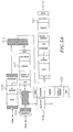
Figure 4 illustrates one implementation of a Gigabit
security processor 410. This implementation includes quad
10/100/1000 GMACs (receivers 420A-D, transmitters 422A-D) with
integrated SERDES (receivers 424A-D, transmitters 426A-D).
Each of the GMACs may be configured to interface with a host
side network or a line side network. The network inputs and
outputs for the GMACs are labeled P1 - P4.
The Gigabit security processor 410 also includes a PL3
interface. The input to the PL3 receiver 436 is labeled PL3
TX. The output of the PL3 transmitter 440 is labeled PL3 RX.
One of the GMACs may be swapped with a PL3 interface. On
the receive side, this is accomplished by a multiplexer 438
that selects either the signal from PL3 receiver 436 or the
GMAC RX(4) 420D to be sent to a data input unit ("DIU") 428.
On the transmit side, a demultiplexer 442 sends output data
from a data routing unit ("DRU") 430 to either the PL3
transmitter 440 or the GMAC TX(4) 422D.
The DIU 428 manages packet flow from the receiver inputs
into the processing path of the Gigabit security processor 410
and may extract and process header information. Packets may
be routed to a bypass path 434, for example, when no security
processing is necessary. This would be the case for non-IPsec
packets flowing through the Gigabit security processor 410.
Packets may be routed to a public key processing component
432. Packets also may be routed to an IPsec processing
component 412 based, for example, on analysis of packet header
information as discussed herein. The Gigabit security
processor 410 includes an internal data memory 414 as well a
memory interface component to access external data memory such
as a serial dynamic random access memory ("SDRAM") 416.
Additional details of one embodiment of the processing path of
a Gigabit security processor are described in U.S. Patent
Application No. 09/610,798 filed on 07/06/00 and entitled
"DISTRIBUTED PROCESSING IN A CRYPTOGRAPHY ACCELERATION CHIP,"
the entire contents of which are hereby incorporated by
reference.
The DRU 430 manages data from the processing path of the
Gigabit security processor 410 to be sent to the device
outputs. Thus, the DRU 430 routes packets to the GMAC
transmitters 422A-C and the demultiplexer 442.
Figures 5A and 5B depict one embodiment of packet
processing operations for the security processor. In Figure
5A, the security processor includes a policy lookup unit 514
and a merge data unit ("MDU") 512. The policy lookup unit
("PSU") 514 receives packet information from the data input
unit ("DIU") 428 to retrieve, when applicable, the header to
append to an incoming packet. The merge data unit 512 merges
the header with the incoming packet from the data input unit
428.
The MDU provides a traffic merge functionality between
the PSU and the DIU. The MDU uses the two management control
words ("MCWs") from the PSU to merge data from both the PSU
and the DIU (bitwise OR of the MCWs). The MDU gives priority
to the locally fetched data fields when both MCWs indicate the
presence of the field.
The BufferData field is inserted after the Ethernet
header for Tunnel mode packets and after the IP header for
Transport Mode packets. The Ethernet header is treated as
separate portion of the BufferData field when EthernetMode=1
(i.e. the Ethernet header can be replaced by data in local
memory) and is always used to replace the original Ethernet
header.
The MDU merges any errors generated by the PSU into the
PacketStatus of the packet received from the DIU for the
requested MCW.
Figure 6 depicts one embodiment of a policy lookup unit
600. The PSU reads information from memory 608 and prepends
the information to the packet. The location in memory of the
SA Data Structure can be specified directly or by selectors in
the SAHandle field as represented by input 602. The PSU may
use the selectors to search a hash based flow table 606 to
determine the location of SA Data Structure. This architecture
may be used for both inbound, outbound and non-Ipsec packets,
providing an extremely flexible mechanism that allows each
packet to be classified into an established flow.
The memory is managed by the host processor using memory
access packets. The memory access packets are serviced by the
PSU in order with all packet requests. The PSU issues memory
read/write commands as well as flow update commands.
The flow updates are special access packets for which the
PSU calculates the hash entry point into the flow table. The
PSU searches out the previous flow selectors (match found) or
the next empty position in the flow table (new flow). It then
updates the flow table with the new flow selector values.
The PSU block receives a set of selectors in the SAHandle
from the DIU along with the MCW. The PSU hashes the selectors
to generate an address unless the address is provided
directly. The SPI is typically used directly as the entry into
the hash table for inbound IPsec packets (indicated in the
SAHandle). In a controlled system, the SPI may be used
directly as the address of the SA Data Structure (no flow
table required for inbound IPsec packets in this case, however
the SA Data Structure size must be fixed to one of four preset
values for all inbound security associations when using this
method).
The resulting hash address is used to read the flow
element from a hash table (different base address for separate
hash tables). The flow element contains one or more flow
entries with selectors that are used to match the original
packet selectors.
A compare unit 610 in the PSU compares the selectors to
the ones found in the flow entries in sequential order. If the
selectors are not found within the base flow element, the rest
of the flow elements are fetched by the PSU. These flow
elements are also searched in order until a match is found. If
no match is found, the packet is flagged with an error 2.
In one embodiment the PSU can process 5 Mpps for flow
lookups when the flow entry is found in the first flow element
(3 entries for IPv4, 1 entry for IPv6). When the PSU goes
beyond the first flow element, data may be stalled in the
pipeline (i.e. could look into 2 elements for 128 byte packets
or 4 elements for 256 byte packets at line rate).
Once the selectors have been resolved (i.e. the flow is
found), the PSU compare block 614 fetches the SA Data
Structure from the SA_PTR location in the flow entry with the
matching selectors.
The policy data (SPData) for an outbound type packet is
compared to the selectors in the SAHandle by the PSU. If the
policy data comparison fails, any further processing of the
packet is not done by the security processor (the PSU does not
update the security association data on a policy failure for
outbound packets). Since the PSU does not drop packets, it
simply provides the MDU with an error flag for this packet.
The MDU will add the error flag to the packet status. The PSU
always consumes the SPData field for an outbound packet.
If the SAUpdate field is present for an outbound packet
type, the OB SA Update block 618 in the PSU will increment the
sequence number and modify the byte count of the packet of the
SAUpdate field and write the result back to memory 620. The
PSU manages the coherency of this operation locally using the
address of the SA Data Structure as exclusive. Since the byte
count is based on the "protected" byte count value, the PSU
adds the packet length plus a fixed value (indicated in the
SAUpdate field) per packet that it processes.
The PSU enforces the soft and hard expiration indications
for lifetime on all packets (notifications passed to the ISU
for expiration generation on inbound packets). The PSU
enforces the soft and hard expirations of lifebyte and
sequence number exhaustion for outbound packets. The PSU
constructs the expiration message sending it through the MDU
datapaths.
The packet length (TOTAL_LEN) and IP header length
(HDR_LEN) are passed to the PSU from the DIU with the
selectors in the SAHandle field (automatically generated by
the security processor). The header length is subtracted from
the protected byte count for Transport ESP packets indicated
in the SAData field.
The protected byte count equations are the following:
The AH protected byte count is used for an AH-ESP bundle.
The PSU consumes the SAHandle field that it received from
the DIU. It provides the data fetched from memory on the
correct channel to the targeted MDU, as represent by line 604.
Figure 7 depicts one embodiment of security association.
data structures for tunnel mode encapsulation. The security
processor provides a flexible encapsulation mechanism by using
a SA Data Structure fetch to prepend information to the
original data packet. The SA Data Structure (see, for example,
structures 700 and 702 in Figure 7) is fetched from local
memory and merged with the original packet by the "Merge Data
Unit (MDU)". The host constructs the SA Data Structure in such
a manner that it provides the necessary encapsulation for the
packet. The security processor then modifies or constructs the
variable fields of the encapsulated packet.
This mechanism is extremely flexible in allowing the host
to do custom encapsulations that include changing Ethernet
headers on a per flow basis. This section will provide a basic
example of the SA Data Structure for encapsulation, but is not
exhaustive.
The security processor SA Data Structure is constructed
by the host in memory that is accessible by the security
processor (i.e., local memory).
The structure includes an MCW that is used to indicate
the fields that are present in the structure. The SA Data
Structure would contain the SAData field for IPsec packets,
but need not have an SAData field for IP packets.
Figure 8 depicts one embodiment of merge operations
performed by the security processor for tunnel mode
encapsulation. The Tunnel mode encapsulation is achieved by
placing the outer IP header and the security header into the
BufferData field of the SA Data Structure 802. For UDP
encapsulation, the UDP header is also included in the
BufferData field. The SECOFF value may be used to indicate the
location of the security header within the packet.
The security processor merges the packet data 800 with
the SA Data Structure 802 to construct an encapsulated packet
804. The BufferData field is placed after the Ethernet header
of the incoming packet. The padding, NextHeader and ICV for
ESP mode are constructed by the security processor.
A new Ethernet header may also be included in the
BufferData field (not shown). The new Ethernet header present
in the SA Data Structure would replace the Ethernet header of
the incoming packet.
Figure 9 depicts one embodiment of packet header fields
900 for Ipv4 tunnel mode encapsulation. IPsec Tunnel mode
uses an outer IP header to tunnel the inner packet. The outer
IP tunnel mode headers are similar for both AH and ESP
protocols with the PROTOCOL field being the only difference
(selected by the host). This section describes how the
security processor processes the encapsulated packets.
The host builds the outer IP header in the SA Data
Structure when the security association is created. The
following sections indicate how the security processor
modifies this header on a per packet basis.
The outer header IP version is not affected by the inner
header IP version. If the outer header is IPv4 then it is
constructed as shown in Figure 9 by the host (in the SA Data
Structure).
The variable fields are modified or copied by the
security processor as indicated by block 902 and the following
paragraphs. All other fields are used directly as formatted on
input.
Type of Service (TOS).
The SAData.Copy_TOS bit is used to determine if the inner
header values are copied to the outer header. If the inner
header is IPv4 and Copy_TOS=1, the TOS is copied from the
inner IPv4 header TOS field. If the inner header is IPv6 and
Copy_TOS=1, the traffic class is copied from the inner IPv6
header to the TOS field in the outer tunnel header. If
Copy_TOS=0, then the value that was created by the host for
this field is used directly (i.e. the security processor does
not change the value). Whenever Copy_TOS=1, the outer tunnel
header TOS byte (created by the host and stored in the SA Data
Structure) must be zero.
Total Length.
The security processor will always re-calculate the Total
Length field whenever the SAData.Cap_En bit is set. The Total
Length field in the outer IP header (from SA Data Structure)
reflects the amount of data that encapsulates the original
packet (does not include Ethernet header nor the IPv6 fixed
header of 40 bytes). The Total Length field is also updated
when the SAData.
Pad_En bit is set to include the additional bytes of pad
that were added to the packet.
Identification (ID).
The 16 bit identification field can be filled in using
the global ID counter in the security processor within each
IPU. Each IPU is given 1/8 of the total available 16 bit space
(via upper 3 bits) to ensure that no values are repeated
within 2^13 packets.
Flags.
The SAData specifies whether to copy the Flags field from
the inner header (DF_Copy). The clear or set don't fragment
(DF) bit is determined by how the host built the header when
DF_Copy=0. If inner header is IPv6 and the SAData specifies
that the DF bit should be copied then the DF bit is set by the
security processor (IPv6 fragmentation headers do not have the
equivalent of the DF bit). Whenever DF_Copy=1, the outer
tunnel header DF bit (created by the host and stored in the SA
Data Structure) must be zero.
Fragment Offset.
The fragment offset must be zero for a tunnel packet (the
security processor will not process outer header fragmented
packets). The security processor will not fragment an outbound
packet unless the Frag_En bit in SAData is set AND the outer
header DF bit is not set.
Time to Live (TTL).
The SAData.Copy_TTL bit specifies if the TTL value is
copied from the inner header or used directly as generated by
the host. For an inner IPv6 header with Copy_TTL=1, the Hop
Limit field is mapped directly to the TTL field. Whenever
Copy_TTL=1, the outer tunnel header TTL field (created by the
host and stored in the SA Data Structure) must be zero.
Protocol.
The Protocol field is specified as either ESP (50) or AH
(51) by the host when constructing the header resulting in hex
values of 0x32 or 0x33 respectively. In the case of an AH+ESP
bundle, the AH value should be used since it is the outer
encapsulation.
This field is not changed by the security processor.
If the value is UDP and SAData.UDP_En=1, the security
processor will calculate the UDP header length. If SECOFF is
not provided as part of the SA Data Structure, the security
processor will assume the AH or ESP header (indicated via the
SAData field) is located after an 8 byte UDP header (i.e.
equivalent to a SECOFF value of 8 bytes).
The host may specify this value to other than UDP, ESP or
AH. In this case, the SECOFF can be used for the security
processor to locate the AH or ESP header.
Checksum.
The checksum value is calculated over the IPv4 header by
the security processor based on the IPv4_Checksum bit in the
SAData.
Source / Destination Address.
The source and destination addresses are ignored by the
security processor except in the calculation of the checksum
value.
Options.
The security processor supports options in the outer
tunnel header stored within the SA Data Structure. The
security processor does not modify these options. The security
processor will automatically mute and restore these options
for AH processing.
Figure 10 depicts one embodiment of merge operations
performed by the security processor for transport mode
encapsulation. The Transport mode encapsulation is achieved
by placing the security header in the BufferData field of the
SA Data Structure 1002.
The BufferData field of the SA Data Structure for a
Transport mode security association is placed after the
initial IP header (including options) of the incoming packet
1000.
The security processor treats the Ethernet header (part
of the BufferData field) as a separate field when merging the
data from the incoming packet 1000 and the SA Data Structure
1002 to generate a merged packet 1004. The Ethernet header is
placed at the beginning of the packet for both Tunnel and
Transport modes.
Figure 11 depicts one embodiment of packet header fields
1100 for Ipv4 transport mode encapsulation. For Transport
mode packets, the security processor modifies the existing IP
header while adding a security header to the packet.
The IP header modifications are similar for both AH and
ESP protocols. This section describes how the security
processor processes the encapsulated packets for Transport
mode IPsec.
The modifications to the IP header for IPv4 Transport
mode packets are shown shaded as represented by block 1102 in
Figure 11.
Total Length.
Table 33 indicates how the Total Length field is
calculated for the different encapsulations by the host.
The Total Length field must accurately represents the original
packet length.
| Total Length Calculation for IPv4 Transport Mode |
| TYPE | TOTAL LENGTH |
| AH | ip + ah = 24 + ip |
| ESP (encryption only) | ip + esp + iv + pad + 2 = 10 + iv + ip + pad |
| ESP(authentication only) | ip + esp + pad + 2 + icv = 22 + ip + pad |
| ESP | ip + esp + iv + pad + 2 + icv = 22 + iv + ip + pad |
| AH + ESP | ip + ah + esp + iv + pad + 2 = 34 + iv + pad |
The fragment offset must be zero for an outbound
Transport mode packet RFC2401 requires that transport mode
packets be processed on the entire datagram.
Time to Live (TTL).
The security processor always decrement the packet TTL.
Protocol.
The security processor copies this field into the
security header as required for AH, ESP or AH-ESP. The
Protocol field is changed by the security processor to either
ESP (50), AH (51) or UDP based on the SAData.UDP_En, SAData.AH
and SAData.ESP bits. In the case of an AH+ESP bundle, the AH
value is used since it is the outer encapsulation.
Checksum.
The checksum value is calculated over the IPv4 header by
the security processor based on the IPv4_Checksum bit in the
SAData.
Source / Destination Address.
The source and destination addresses are ignored by the
security processor except in the calculation of the checksum
value and policy verification.
Options.
The security processor supports options in the transport
IP header or the original packet or they may be added via the
SA Data Structure.
The security processor does not modify these options. The
security processor will automatically mute and restore these
options for AH processing.
Figure 12 depicts one embodiment of merge operations
performed by the security processor for tunnel mode
decapsulation to generate a merged packet 1204. The security
processor decapsulation logic uses a similar mechanism
described above for Encapsulation. The SA Data Structure 1202
is prepended to the packet 1200 by the security processor
prior to packet processing. The prepended data provides the
SAData information along with the policy data required to
completely process the packet. The merge operation for inbound
packets occurs in the same manner as outbound packets.
Typically, the only BufferData for an inbound packet would be
an optional new Ethernet header.
The merge processing for inbound tunnel mode processing
is shown in Figure 12. It follows the same rules as outbound
merge processing. Similarly, transport mode merge processing
for inbound packets follows the same rules as outbound
processing in that the BufferData field is inserted after the
IP header with the exception of the Ethernet header.
The security processor is required to locate the UDP
encapsulating header (if present) and the security header in
the packet. Additionally, it must process non-IPsec traffic
which might include IKE packets. The security processor uses
the information in the security association to decode the
packet contents. The SAData field indicates the mode of the
packet (transport or tunnel) as well as the format of the
packet fields.
Figures 13A and 13B depict embodiments of packet header
fields for Ipv4 tunnel mode decapsulation. The security
processor can optionally decapsulate inbound tunnel mode
packets based on the SAData information. The security
processor provides the capability to update the inbound SA
information and verify the policy of the decrypted and
decapsulated packet. The outer tunnel header and the security
header(s) are removed from the packet by the security
processor.
In inbound AH tunnel mode the security processor verifies
that the ICV value in the AH header matches the calculated ICV
for the packet. If the Cap_En bit is set, the outer IPv4
header and the AH header are removed from the packet.
The security processor can optionally decrement the inner
IP header TTL (Decrement_TTL=1) and re-calculate the header
check-sum during decapsulation. Inner IPv6 headers are handled
in the same manner as the inner IPv4 header (Hop Limit decremented
based on Decrement_TLL). Outer IPv6 headers are removed
in a similar manner as outer IPv4 headers.
In inbound ESP tunnel mode the security processor
verifies that the ICV value in the ESP trailer matches the
calculated ICV for the packet. The packet is decrypted
according to the information in SAData. If the Cap_En bit is
set, the outer IPv4 header, ESP header, IV (only removed if
Write_IV=1) and ESP trailer are removed from the packet.
The security processor can optionally decrement the inner
IP header TTL (Decrement_TTL=1) and re-calculate the header
check-sum during decapsulation. Inner IPv6 headers are handled
in the same manner as the inner IPv4 header (Hop Limit
decremented based on Decrement_TLL). Outer IPv6 headers are
removed in a similar manner as outer IPv4 headers.
The security processor provides optional decapsulation of
the security headers for transport mode packets.
In inbound AH transport mode the security processor
copies the NextHeader field from the AH header into the
Protocol field of the IP header (replacing the previous value
of AH). The TTL is decremented in the header and the checksum
recalculated by the security processor.
The security processor verifies that the ICV value in the
AH header matches the calculated ICV for the packet. If the
Cap_En bit is set, the AH header is removed from the packet.
Figure 14 depicts one embodiment of merge operations for
non-IPsec packets to generate a merged packet 1404. The
security processor can process non-IPsec traffic packets 1400
on a separate flow (or SA Data Structure) or in combination
with IPsec traffic.
The host may provide an SAUpdate field when processing
non-IPsec traffic. If the policy information in the SAUpdate
fails, the security processor tags the packet as an error. The
MCW can be set to drop the packet, bypass the packet.
A flow for a non-IPsec packet can be configured as BYPASS
or DROP using just the MCW as the SA Data Structure 1402. For
the BYPASS case, the host may chose to provide PacketContext
that contains the result of the flow lookup done by the
security processor for this packet. The resulting packet would
be forwarded to the host with the PacketContext field included
as part of the packet.
For in-band host communication, the SA Data Structure
1402 would include a BufferData field with an Ethernet header
and the flow identification that would subsequently be routed
to the host.
Figure 15 depicts one embodiment of a processor interface
block. The processor interface block ("PIB") is used for
packet encapsulation and packet decapsulation in the security
processor. The PIB allows a processor (RISC) core to modify
packets as they flow through a FIFO.
The processor interface block is an RTL wrapper that
communicates with the RISC engine. Packets are written into a
2-kilobyte buffer to be modified by the RISC engine. Free
memory space can be inserted so that extra fields can be added
to the output packet for encapsulation and fragmentation. For
packet fragmentation, PIB supports a region lock feature such
that it does not over-write the designated part of the 2kB
buffer with input packet data. After RISC finished
processing, the modified packets are read from the buffer and
sent to the next module. The PIB also includes External
Interface supporting RISC (master) access and data buffer
(target) access. It is used for low bandwidth application
such as checksum calculation.
The 2kB odd/even-word memories are split into two 1kB
dual-ported memories. Each word of a packet is alternately
written into the odd or even-word 1kB memories by the IPU/OPU
wrappers. The memories are byte-addressable so that they can
support byte, half-word and word memory accesses. Four
sources arbitrate for these four memory ports.
- The RISC engine issues load and store commands.
- The IPU/OPU block writes packets into the memory.
- The DMA reads packets from memory and sends them
out.
- The External Interface reads/writes from/to memory
when calculating the IP checksum and IP options.
By design the four sources will not access the same
memory addresses. However, the four sources may all attempt
to access the same 1kB of memory. When this occurs, only two
sources will gain access to the memory. The odd-word/even-word
memory partition reduces the probability of long-lasting
collisions.
When used in the IPU wrapper, the RISC and IPU packet
writes are given priority in arbitration over the External
Interface and the DMA engine. When used in the OPU wrapper,
the RISC and the DMA engine are given priority in arbitration
over the External Interface and OPU packet writes.
The justification for this priority scheme is described
below:
- The RISC core does not support variable-latency
loads/stores and can never be stalled without causing
functional errors. In addition, the number of RISC
cycles/packet is very short and should not be wasted in
arbitration.
- Priority should be given to the higher bandwidth
interface. In the IPU wrapper, the DIU-to-IPU interface
must support 2.4Gbps and the IPU-to-SPU interface must
support 600Mbps. In the OPU wrapper the OPU-to-DRU
interface must support 2.4Gbps and the SPU-to-OPU interface
must support 600Mbps.
Based on the priority scheme, the dual-port memories
(Figure 16) are set up as follows:
The Port A Arbiters give priority to packet data input
for IPU (or packet data output for OPU) when both input packet
and output packet are trying to access the same memory. For
the majority of accesses, alternate memory addresses (even,
odd, even, odd, ...) are read/written. Consequently, after the
lower priority access is stalled for one cycle in case of
conflict, the interfaces will be accessing different memories
at any given time.
The Port B Arbiters give priority to RISC accesses over
External Interface accesses. While these accesses are more
sporadic than either packet data input or packet data output
accesses, their bandwidth requirements are significantly lower
and well within the memories' limit.
These memories support the following memory allocation
and de-allocation schemes. These schemes allow the RISC
processor to spend fewer cycles handling descriptors.
- Field Removal: In a standard FIFO, every word that
is written into the FIFO is read out. In this memory, every
word that is written is not read out. This scheme allows
the IPU and OPU to remove fields. For example, the IPU and
OPU must always remove the SAU field. The RISC core does
not write an Output Descriptor for the SAU field. When the
next Output Descriptor is written (SAD descriptor), the SAU
field memory is automatically de-allocated.
- Field Re-ordering: In a standard FIFO, the first
word in is always the first word out. This scheme allows
words to be re-ordered. The RISC core may write an Output
Descriptor to one of the two addresses: one to de-allocate
buffer space while PIB is sending the data out, and one not
to de-allocate until that of a later Output Descriptor is
de-allocated. When re-ordering fields, the RISC core is
responsible for sending the Output Descriptor to the correct
address. For example, IPU must insert the bdata_encap field
inside of the first buffer data field for transport-mode
packets. The diagram below illustrates how the wrapper and
the RISC core work together to support field reordering:
| Input Descriptor Order | Output Descriptor Order |
| A | B (don't de-allocate) |
| B | A (de-allocate) |
| C | C (de-allocate) |
The Output Descriptor for field B is sent to the "No
De-allocation" address. Otherwise, field A would be removed
and could be overwritten before being read. The Output
Descriptor for field A is sent to the address that de-allocates
memory. As field A is read out, each word is de-allocated.
The Output Descriptor for field C is sent to the
memory address that de-allocates memory. Field B is de-allocated
and as field C is read out each word is de-allocated.
- Fragmentation support: The RISC core may write a
Lock Descriptor to lock a contiguous region of the buffer
space. After a region is locked, PIB will not over-write
the designated region with new packet data. No data output
is associated with a Lock Descriptor. This feature is to
support packet fragmentation when a single input packet
spawns multiple output fragments. In such case, the header
fields from the input packet are replicated (with minimal
modifications) in all the output fragments. The specific
region in the memory buffer needs to be locked and is then
prevented from being de-allocated. After the RISC core:
finishes updating the last output packet fragment, it
unlocks the region by setting Unlock Region command in an
Output Descriptor. PIB supports only one (1) lock region at
any time. The RISC core needs to unlock a region before it
locks another one.
The IPU/OPU writes descriptors into the Input Descriptor
FIFO (IDF). There are three categories of descriptors:
- Field Descriptors are written into the IDF by the
IPU/OPU after the field has been completely written into the
2kB memory.
- Free Space Descriptors are written into the IDF by
the IPU/OPU once there is enough room in the 2kB memory for
the free space to be allocated. The PIB indicates the
number of available words in the 2kB memory. Free space is
not initialized in memory. This decreases the overhead of
reserving free space for a packet.
- Jump Descriptors describe jump addresses for the
RISC engine. The code_jump Descriptor is a special type of
Jump Descriptor that acts as a semaphore between IDM and the
RISC engine.
Each Input Descriptor is associated with a field index
(din_desc_idx), which is used by the RISC core to access the
specific descriptor at a pre-determined address.
The Input Descriptor Memory (IDM) consists of fixed
addresses that may be read and written by the RISC engine.
Each address contains a descriptor that describes a part of
the packet. This reduces the time that the RISC engine spends
parsing control structures.
After the RISC core read a specified Input Descriptor, it
checks for a non-zero value to indicate the descriptor is
valid. For Field type descriptors, it may simply check
whether the length field is zero or not.
The IDM is double-buffered to avoid delays when the RISC
engine switches processing from the current packet to the next
packet. Once the last descriptor for the current packet is
written into the current block of IDM, the next packet's
descriptors are written into the next IDM buffer.
A typical interaction between IDF, IDM and the RISC
engine for a packet is described below:
ODM responds to Output Descriptor and Lock Descriptor
accesses from the RISC core, merges Output Descriptors if
possible, and sends them serially to Output Descriptor FIFO
(ODF).
For Output Descriptors, ODM checks whether consecutive
ones correspond to contiguous address spaces, merges them into
one if so, and sends to ODF. As a result, ODM does not send a
merged Output Descriptor to ODF until it can verify the next
one is not continuous to the current one. The exception is
when the current one has a non-zero command field, then it is
sent right away.
The RISC engine needs to have a back-pressure feature
such that when ODF is full, PIB can stall the RISC engine from
submitting more Output Descriptors. ODF is responsible of
transmitting Output Descriptors to DMA as requested.
The DMA engine reads descriptors from ODF. Its basic
function is to fetch data from the 2kB memory and sends them
out through the output interface. Unless a region is locked
or the RISC has requested no de-allocation, after the data
pointed by an Output Descriptor is transmitted; the
corresponding buffer space is de-allocated and is free to
store new input packet data. In addition, it decodes embedded
command, and generates the side-band signals.
DMA supports the following functions as triggered by
various flags.
- Region Lock: If instructed, DMA locks up a
contiguous region in the 2kB memory buffer. As a result,
PIB will not write input packet data words to it. When the
write pointer reaches the address preceding to the region,
it will jump to the region's subsequent address for the next
data. This is to support the fragmentation feature. The
locked region stores the fields common to all the fragments.
After the RISC core finishes processing the last fragment,
it notifies PIB of unlocking the region to store input
packet data.
- Output Data Send Notify: This is to be utilized with
the region lock feature to perform packet fragmentation.
After DMA sends out the data designated by an Output
Descriptor, if the RISC engine has set Notify after Sent
command, DMA asserts Output Data Sent Done register bit to
notify the RISC core, which will then alter the content and
submit another Output Descriptor for the modified data. The
bit resets itself after being read by the RISC core.
- Side-band Signals: The RISC core may set End of
Fragment command and/or Packet Error bit in an Output
Descriptor, and DMA then generates corresponding side-band
signals. Moreover, if the RISC core writes the Output
Descriptor to the EOP indication address, PIB asserts
dout_pkt_sync (active-low) when sending out the
corresponding packet data.
- Delayed Memory De-allocation: This is to support
field re-ordering. If the RISC core writes an Output
Descriptor to the "No De-allocation" address, DMA does not
de-allocate the corresponding memory space until the next
one (with the flag not set) is de-allocated.
The following is an example of how fragmentation is done.
Suppose IPU/OPU is sending the following Input Descriptors to
PIB.
| Desc | Cat | Type | Address | Length | |
| 1 | Field | Header | 0x0000 | 12 |
| 2 | Free | Pseudo Status Word | 0x000C | | 4 |
| 3 | Field | Payload # | 1 | 0x0010 | 16 |
| 4 | Field | Payload # | 2 | 0x0020 | 16 |
| 5 | Field | Payload #3 | 0x0030 | 16 |
| 6 | Field | Status Word | 0x0040 | | 4 |
PIB transfers the above descriptors to their
corresponding space in IDM. The descriptors #3, #4, and #5
are of the same type so they will be serially accessed at the
same address. The RISC core performs fragmentation by writing
the following Output Descriptors to ODM.
| Desc | Cat | Type | Address | Length | Comments | |
| 1 | Lock | | 0x0000 | | 16 | This locks up the region to store Header and Pseudo Status Word. No output data is sent. |
| 2 Sent | Field | Header | 0x0000 | 12 | RISC sets Notify after command. |
| 3 | Field | Payload # | 1 | 0x0010 | 16 |
| 4 | Field | Pseudo Status Word | 0x000C | | 4 | RISC sets End of Fragment command. |
| The RISC engine waits until Output Data Sent Done bit is asserted, and modifies Header data. |
| 5 | Field | Header | 0x0000 | 12 | RISC sets Notify after Sent command. |
| 6 | Field | Payload # | 2 | 0x0020 | 16 |
| 7 | Field | Pseudo Status Word | 0x000C | | 4 | RISC sets End of Fragment command. |
| The RISC engine waits until Output Data Sent Done bit is asserted, and modifies Header data. |
| 8 | Field | Header | 0x0000 | 12 | RISC sets Unlock Region command. |
| 9 | Field | Payload #3 | 0x0030 | 16 |
| 10 | Field | Status Word | 0x0040 | | 4 | RISC sets End of Fragment command and writes to EOP address. |
External Interface is composed of two access pipes. As a
master, RISC may initiate read/write transactions from/to the
external bus through External Interface. Moreover, a node on
the external bus may initiate accesses on PIB 2kB data memory
(target) through the second pipe. PIB does all necessary
address translations between internal address space and
external bus address.
It should be appreciated that the inventions described
herein are applicable to and may utilize many different
protocols and standards and modifications and extensions of
those protocols and standards including, for example and
without limitation, IP, TCP, UDP, ICMP, IPsec, SSL and FCsec.
Moreover, a variety of cryptographic and signature algorithms
and modifications and extensions thereof may be used. The
invention may be practiced using tunnel mode and/or transport
mode packet processing.
It should also be appreciated that the inventions
described herein may be constructed using a variety of
physical components and configurations. For example, a
variety of hardware and software processing components may be
used to implement the functions of the host processors,
security processors, network processors and the Ethernet
processors/controllers and the other components and processes
described herein. These hardware and software components
include, without limitation, processors and associated data
memory, state machines and logic and may involve execution of
software, firmware or other code. Such components may be
combined on one or more integrated circuits. For example,
several of these components may be combined within a single
integrated circuit. Some components may be implemented as a
single integrated circuit. Some components may be implemented
using several integrated circuits.
In addition, the components and functions described
herein may be connected in many different ways. Some of the
connections represented by the lead lines in the drawings may
be in an integrated circuit, on a circuit board, over a
backplane to other circuit boards, over a local network and/or
over a wide area network (e.g., the Internet). Thus, some of
the components may be located in a remote location with
respect to the other components. Typically, one or more of
the connections represented by the lead lines in the drawings
may, for example, comprise a data network. In addition, these
connections may be made with physical wire, fiber and/or
wireless connections, for example.
A wide variety of devices may be used to implement the
data memories (e.g., the databases and non-volatile memories)
discussed herein. For example, a data memory may comprise
one or more RAM, disk drive, SDRAM, FLASH or other types of
data storage devices.
The invention may be practiced using different types of
cipher engines. For example, in one embodiment of the
invention data is decrypted using a block cipher, rather than
a stream cipher.
In summary, the invention described herein teaches
improved packet processing techniques. While certain
exemplary embodiments have been described in detail and shown
in the accompanying drawings, it is to be understood that such
embodiments are merely illustrative of and not restrictive of
the broad invention. In particular, is should be recognized
that the teachings of the invention apply to a wide variety of
systems and processes that are configurable. It will thus be
recognized that various modifications may be made to the
illustrated and other embodiments of the invention described
above, without departing from the broad inventive scope
thereof. In view of the above it will be understood that the
invention is not limited to the particular embodiments or
arrangements disclosed, but is rather intended to cover any
changes, adaptations or modifications which are within the
scope and spirit of the invention as defined by the
appended claims.