TECHNICAL FIELD
The present invention relates to a disk cartridge in
which a disk-like recording medium such as an optical disk, a
magneto-optical disk and a magnetic disk is accommodated within
a disk compartment of a cartridge housing, a disk recordingmedium
device in which the disk-like recording medium is accommodated
within the disk compartment so as to become freely rotatable
and a disk recording and/or reproducing apparatus for recording
and/or reproducing informationby using this disk-like recording
medium.
BACKGROUND ART
As a disk recording medium device in which a disk-like
recording medium capable of recording and/or reproducing
information such as audio data, video data or computer data is
accommodated within a cartridge housing so as to become freely
rotatable, there is known a disk recording medium device having
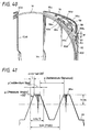
an arrangement shown in FIG. 42, for example. This disk recording
medium device 1 is an information recording media which
incorporates therein a write once magneto-optical disk on which
users are able to record (write) information such as computer
data later on.
This disk recording medium device 1 comprises a
cartridge housing 2 composed of a pair of upper shell 2a and
lower shell 2b, a magneto-optical disk 4 accommodated within
a disk compartment 3 of this cartridge housing 2 so as to become
freely rotatable and so forth. The cartridge housing 2 has on
its upper and lower surfaces provided an upper and lower opening
portion 5 that extends from a central portion to one side. This
opening portion 5 can be opened and closed by a shutter member
6 that can slide along one side. The shutter member 6 is constantly
spring-biased in the direction to close the opening portion 5
under spring force of a spring, not shown. Reference numeral
6a denotes a presser member for preventing a tip end portion
of the shutter member 6 from being disengaged from the opening
portion inadvertently.
The magneto-optical disk 4 has at its central portion
provided a disk-like center hub 7 made of metal. This center
hub 7 is located at the position opposing to the inner end portion
of the opening portion 5, i.e. located at substantially the
central portion of the cartridge housing 2. A turntable provided
on the main body side of an information recording and reproducing
apparatus is mounted to the center hub 7. The magneto-optical
disk 4 is chucked to the turntable and thereby the magneto-optical
disk is rotated at a predetermined velocity (e. g. constant linear
velocity) . At that time, a magneto-optical pickup device of which
the head portion is inserted into the opening portion 5 functions
to record or reproduce information on or from the magneto-optical
disk 4.
However, in the conventional disk recording medium
device having the above-mentioned arrangement, the shutter
member 6 that is provided on the cartridge housing 2 so as to
become freely slidable is constantly spring-biased in the
direction in which it closes the opening portion 3 by a spring.
When the disk recording medium device is in use, the shutter
member 6 is slid in the direction in which it opens the opening
portion 3 to open the opening portion against spring-biasing
force of this spring. To this end, a disk recording and reproducing
apparatus that records and reproduces an information signal by
using this disk recording medium device 1 needs an open and hold
mechanism for holding the shutter member 6 at the opening position
in order to hold the opening portion 3 in the opened state while
the disk recording medium device is in use.
While such open and hold mechanism is generally
provided on the disk recording and reproducing apparatus , various
vibration sources are existing on the disk recording and
reproducing apparatus and shocks are applied to the disk
recording and reproducing apparatus from the outside unavoidably.
Vibrations generated from this disk recording and reproducing
apparatus or shocks inputted to the disk recording and
reproducing apparatus from the outside are transmitted through
the open and hold mechanism to the disk recording medium device
1. As a result, when vibrations from the disk recording and
reproducing apparatus are applied to the disk recording medium
device 1, vibrations are transmitted to the magneto-optical disk
4 and a magneto-optical head of a magneto-optical pickup device
and the like. There arises a problem in which an information
signal is read out from and written in the magneto-optical disk
1 inaccurately.
When external shocks are applied to the disk recording
medium device 1, it is unavoidable that the open and hold mechanism
for holding the shutter member 6 at the opening position is
disengaged from the disk recording and reproducing apparatus.
In such case, the shutter member 6 that intends to move toward
the closing direction is brought in contact with the optical
head of the optical pickup device and the turntable. As a result,
there is a risk that the optical head will be broken or that
the shutter member 6 itself will be broken.
In particular, as a storage capacity of an optical
disk is increasing progressively and a recording density is
increasing progressively, pitches of recording patterns is
becoming narrower and linear density is increasing more in recent
years. Thus, when an information recording surface of a magnetic
recording medium such as an optical disk and a magneto-optical
disk is vibrated or smudged by dusts and the like, such vibrations
and the smudged information recording surface hinder the optical
pickup device from reading or writing information correctly.
So that information cannot be read out from and written in the
disk recording medium device normally.
In view of the aforesaid aspect, it is an object of
the present invention to provide a disk cartridge, a disk
recording medium device and a disk recording and/or reproducing
apparatus in which when a shutter member has finished opening
the opening portion, pressure from an open and hold mechanism
of an external apparatus and which is used to hold the shutter
member at the opening position can be prevented from being applied
to a cartridge housing so that the shutter member can be held
at the opening position by an inside mechanism.
DISCLOSURE OF THE INVENTION
In a disk cartridge according to the present invention,
there is provided a disk cartridge comprising a cartridge housing
in which a disk compartment is formed between an upper shell
and a rotary member or between the rotary member and a lower
shell by combining the upper shell, the rotary member and the
lower shell, the rotary member is supported by at least one of
the upper shell and the lower shell so as to become freely rotatable
and an opening portion is formed on at least one of the upper
shell and the lower shell or at least one of the upper shell
and the lower shell and the rotary member, a shutter member
provided on the cartridge housing so as to become movable between
the opening position at which it opens the opening portion and
the closing position at which it closes the opening portion in
response to rotation of the rotary member, a shutter fixing means
for holding the shutter member in the closed state at the closing
position and in which the shutter member is held in the opened
state at the opening position by the shutter fixing means.
Further, in a disk cartridge according to the present
invention, there is provided a disk cartridge comprising a
cartridge housing in which a disk compartment is formed by
combining an upper shell and a lower shell and an opening portion
is provided on at least one of the upper shell and the lower
shell, a shutter member provided on the cartridge housing so
as to become movable between the opening position at which it
opens the opening portion and the closing position at which it
closes the opening portion and a shutter fixing means for holding
the shutter member in the closed state at the closing position
and in which the shutter member is held in the opened state at
the opening position by the shutter fixing means.
In a disk recording medium device according to the
present invention, there is provided a disk recording medium
device comprising a cartridge housing in which a disk compartment
is formed between an upper shell and a rotary member or between
the rotary member and a lower shell by combining the upper shell,
the rotary member and the lower shell, the rotary member is
supported by at least one of the upper shell and the lower shell
so as to become freely rotatable and an openingportion is provided
on at least one of the upper shell and the lower shell or between
at least one of the upper shell and the lower shell and the rotary
member, a disk-like recording medium accommodated within the
disk compartment so as to become freely rotatable, a shutter
member provided on the cartridge housing so as to become movable
between the opening position at which it opens the opening portion
and the closing position at which it closes the opening portion
in response to rotation of the rotary member and a shutter fixing
means for holding the shutter member in the closed state at the
closing position and in which the shutter member is held in the
opened state at the opening position by the shutter fixing means.
Further, in a disk recording medium device according
to the present invention, there is provided a disk recording
medium device comprising a cartridge housing in which a disk
compartment is formed by combining an upper shell and a lower
shell and an opening portion is provided on at least one of the
upper shell and the lower shell, a disk-like recording medium
accommodated within the disk compartment so as to become freely
rotatable, a shutter member provided on the cartridge housing
so as to become movable between the opening position at which
it opens the opening portion and the closing position at which
it closes the opening portion and a shutter fixing means for
holding the shutter member in the closed state at the closing
position and in which the shutter member is held in the opened
state at the opening position by the shutter fixing means.
In a disk recording and/or reproducing apparatus
according to the present invention, there is provided a disk
recording and/or reproducing apparatus comprising a disk
recording medium device including a cartridge housing in which
a disk-like recording medium is accommodated within a disk
compartment so as to become freely rotatable, a shutter member
movable between the opening position at which it opens an opening
portion provided on the cartridge housing so as to expose a part
of the disk-like recording medium and the closing position at
which it closes the opening portion and a shutter fixing means
for holding the shutter member in the closed state at the closing
position, a shutter opening and closing means for opening and
closing the opening portion by moving the shutter member in
response to inserting and ejecting operations of the disk
recording medium device and a table drive apparatus to which
the disk recording medium device is loaded detachably and which
is inserted into the disk recording and/or reproducing apparatus
from the opening portion opened by the shutter opening and closing
means to chuck and rotate the disk-like recording medium, wherein
the cartridge housing is formed by combining the upper shell
and the lower shell or by combining the upper shell, the rotary
member and the lower shell, the disk compartment is formed between
the upper shell and the lower shell or between the upper shell
and the rotary member or between the rotary member and the lower
shell and the shutter member is held in the opened state at the
opening position by the shutter fixing means.
BRIEF DESCRIPTION OF DRAWINGS
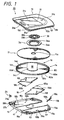
FIG. 1 is an exploded perspective view showing a disk
recording medium device according to an embodiment of the present
invention from the upper surface side in an exploded fashion.
FIG. 2 is an exploded perspective view showing a disk
recording medium device according to an embodiment of the present
invention from the lower surface side in an exploded fashion.
FIG. 3 is a perspective view showing an upper shell
of a disk cartridge for use with a disk recording medium device
according to the present invention from the upper surface side.
FIG. 4 is a bottom view of the upper shell of the disk
cartridge for use with the disk recording medium device according
to the present invention.
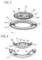
FIG. 5 is a perspective view showing a chucking ring
and a ring holder attached to the upper shell of the disk cartridge
for use with the disk recording medium device according to the
present invention from the upper surface side.
FIG. 6 is a perspective view showing the central
portions of the chucking ring and the ring holder attached to
the upper shell of the disk cartridge for use with the disk
recording medium device according to the present invention from
the lower surface side in a cross-sectional fashion.
FIG. 7 is a perspective view showing a rotary member
of the disk cartridge for use with the disk recording medium
device according to the present invention from the upper surface
side.
FIG. 8 is a plan view of the rotary member of the disk
cartridge for use with the disk recording medium device according
to the present invention.
FIG. 9 is a perspective view showing a pair of shutter
members of the disk cartridge for use with the disk recording
medium device according to the present invention from the upper
surface side.
FIG. 10 is a perspective view showing the assembled
state of a pair of shutter members of the disk cartridge for
use with the disk recordingmedium device according to the present
invention from the upper surface side.
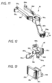
FIG. 11 is a perspective view showing a lock member
of the disk cartridge for use with the disk recording medium
device according to the present invention from the upper surface
side.
FIG. 12 is a perspective view showing the lock member
of the disk cartridge for use with the disk recording medium
device according to the present invention from the lower surface
side.
FIG. 13 is a perspective view showing a mis-erase
prevention member of the disk cartridge for use with the disk
recording medium device according to the present invention from
the upper surface side.
FIG. 14 is a perspective view showing the lower shell
of the disk cartridge for use with the disk recording medium
device according to the present invention from the upper surface
side.
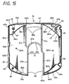
FIG. 15 is a plan view of the lower shell of the disk
cartridge for use with the disk recording medium device according
to the present invention.
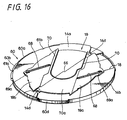
FIG. 16 is a perspective view showing the state in
which a pair of shutter members is attached to the rotary member
of the disk recording medium device shown in FIG. 1 to thereby
close the inside opening portion.
FIG. 17 is a perspective view showing an outward
arrangement of the disk recording medium device shown in FIG.
1.
FIG. 18 is a perspective view showing the disk
recording medium device shown in FIG. 17 from the lower surface
side and illustrates the state in which the opening portion is
closed by closing a shutter mechanism.
FIG. 19 is a perspective view showing the disk
recording medium device shown in FIG. 17 from the lower surface
side and illustrates the state in which the opening portion is
opened by opening the shutter mechanism.
FIG. 20 is an explanatory cross-sectional view taken
along the lines connecting a pair of positioning holes of the
disk recording medium device shown in FIG. 17.
FIG. 21 is an explanatory diagram view to which
reference will be made in explaining chucking in the disk
recording medium device according to the present invention and
illustrates, in a cross-sectional fashion, the state obtained
before an optical disk is attached to the turntable.
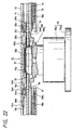
FIG. 22 is an explanatory diagram to which reference
will be made in explaining chucking in the disk recording medium
device according to the present invention and illustrates, in
a cross-sectional fashion, the state obtained after the optical
disk has been attached to the turntable.
FIGS. 23 are perspective views to which reference will
be made in explaining the manner in which the rotary member is
elevated and lowered relative to the upper shell when the opening
portion of the disk recording medium device according to the
present invention is opened and closed, wherein FIG. 23A is an
exploded perspective view, FIG. 23B is a perspective view showing
the state in which the rotary member is lowered relative to the
upper shell and FIG. 23C is a perspective view showing the state
in which the rotary member is elevated relative to the upper
shell.
FIG. 24 is a diagram to which reference will be made
in explaining how to calculate clearances among a cam portion
of the upper shell and a cam protrusion of a rotary member of
the disk cartridge according to the present invention and shows
sizes of the upper shell, the rotary member, the lower shell
and the shutter member in the form of reference numerals.
FIG. 25 is a diagram to which reference will be made
in explaining how to calculate a clearance between a cam portion
of the upper shell and a cam protrusion of a rotary member of
the disk cartridge according to the present invention and shows
its clearance in the form of reference numerals.
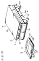
FIG. 26 is a perspective view showing a disk recording
and/or reproducing apparatus according to an embodiment of the
present invention.
FIG. 27 is a perspective view showing a feed screw
drive device of the disk recording and/or reproducing apparatus
according to the present invention and illustrates a part of
a power transmission member and so forth in a cross-sectional
fashion.
FIG. 28 is an explanatory block diagram showing a
circuit arrangement of a disk recording and/or reproducing
apparatus according to an embodiment of the present invention.
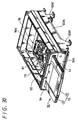
FIG. 29 is a perspective view showing the state
presented before the disk recording medium device is loaded onto
the table drive apparatus of the disk recording and/or
reproducing apparatus according to the present invention.
FIG. 30 is a perspective view showing the state
presented when the disk recording medium device is being loaded
onto the disk recording and/or reproducing apparatus according
to the present invention.
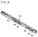
FIG. 31 is a perspective view showing a shutter opening
and closing means that opens and closes the shutter mechanism
of the disk recording medium device according to the present
invention.
FIG. 32 is a diagram to which reference will be made
in explaining the manner in which the shutter mechanism of the
disk recording medium device according to the present invention
is opened and closed by the shutter opening and closing means
and illustrates the state obtained until an initial operation
convex portion of a rack rod reaches to an opening window of
the lower shell after a pair of shutter members had closed the
opening portion of the lower shell and the opening portion of
the rotary member completely.
FIG. 33 is a plan view showing a main portion of FIG.
32 in an enlarged-scale.
FIG. 34 is a perspective view showing a main portion
of FIG. 33 in a more enlarged-scale.
FIG. 35 is a diagram to which reference will be made
in explaining the manner in which the shutter mechanism is opened
and closed by the shutter opening and closing means in the state
in which the lower shell is removed from the disk recording medium
device according to the present invention and illustrates the
state obtained when a pair of shutter members is slightly opened
(approximately 5°) after the initial operation convex portion
of the rack member had engaged with an initial operation concave
portion of the rotary member to enable the rotary member begin
to rotate.
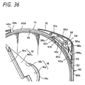
FIG. 36 is a plan view showing a main portion in an
enlarged-scale and to which reference will be made in explaining
relationships among the rotary member, the lower shell, the lock
member and the like in the state in which the upper shell is
removed from the recording medium device shown in FIG. 35.
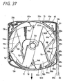
FIG. 37 is a diagram to which reference will be made
in explaining the manner in which the shutter mechanism is opened
and closed by the shutter opening and closing means in the state
in which the lower shell is removed from the disk recording medium
device according to the present invention and illustrates the
state obtained when a pair of shutter members is largely opened
(approximately 30°) after a rack portion of the rack rod had
meshed with a gear portion of the rotary member.
FIG. 38 is a plan view showing a main portion in an
enlarged-scale and to which reference will be made in explaining
relationships among the rotary member, the lower shell, the lock
member and the like in the state in which the upper shell is
removed from the disk recording medium device shown in FIG. 37.
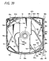
FIG. 39 is a diagram to which reference will be made
in explaining the manner in which the shutter mechanism is opened
and closed by the shutter opening and closing means in the state
in which the lower shell is removed from the disk recording medium
device according to the present invention and illustrates the
state obtained when a pair of shutter members opens the opening
portion completely (approximately 55°) after a stopper convex
portion of the rack member had engaged with a set position concave
portion of the rotary member.
FIG. 40 is a plan view showing a main portion in an
enlarged-scale and to which reference will be made in explaining
relationships among the rotary member, the lower shell, the lock
member and the like in the state in which the upper shell is
removed from the disk recording medium device shown in FIG. 39.
FIG. 41 is an explanatory diagram showing a main
portion and to which reference will be made in explaining a tooth
form of the rack portion of the rack rod shown in FIG. 31.
FIG. 42 is a perspective view showing a disk cartridge
according to the prior art.
BEST MODE FOR CARRYING OUT THE INVENTION
Embodiments of the present invention will be described
below with reference to the accompanying drawings. FIGS. 1 to
41 are diagrams showing embodiments of a disk cartridge, a disk
recording medium device and a disk recording and/or reproducing
apparatus according to the present invention.
In the present application, "disk cartridge" refers
to such a disk cartridge having a main arrangement comprising
an upper shell, a lower shell or an upper shell, a lower shell
and a rotary member and one or a pair of shutter members (two
shutter members and a combination of more than three shutter
members may be possible) and a housing presented before a
disk-like recording medium is accommodated. A "disk recording
medium device" refers to such a disk recording medium device
in which a disk-like recording medium is accommodated within
a disk compartment and which comprises a combination of a
cartridge housing and a disk-like recording medium. Further,
"disk recording and/or reproducing apparatus" refers to such
a disk recording and/or reproducing apparatus which comprises
a combination of a disk recording medium device, a table drive
apparatus and the like.
A disk recording medium device 10 including a disk
cartridge according to the present invention accommodates
therein a read-only optical disk in which various information
signals such as a music signal as audio information and a video
signal and a music signal as video information are recorded in
advance or an optical disk in which information signals such
as audio information and video information can be recorded only
once (write once optical disk) or an optical disk 11 in which
information signals such as audio information and video
information can be recorded repeatedly (rewritable optical disk)
as a disk-like recording medium.
However, the disk-like recording medium is not limited
to the above-mentioned optical disks and a magnetic disk having
a magnetic thin film layer formed on the surface of a thin disk
to store information based upon the magnetization state of the
specific position, a magneto-optical disk capable of writing
or reading information in or out of a similarly formed magnetic
thin film layer by the use of an optical head and a magnetic
head and other disk-like recording mediums can be applied to
the present invention, for example.
The disk recordingmediumdevice 10 comprises, as shown
in FIGS. 1 and 2, a cartridge housing 12 formed by combining
a pair of an upper shell 13, a rotary member 14 and a lower shell
15, an optical disk 11 accommodated within a disk compartment
16 formed within this disk cartridge 12 so as to become freely
rotatable, a pair of shutter members 19a, 19b for opening and
closing an inside opening portion 18 and an outside opening
portion 17 formed in the rotary member 14 and the lower shell
15 and the like. The disk cartridge is obtained by removing the
optical disk 11 from this disk recording medium device 10.
Since the disk recording medium device 10 generally
uses the optical disk 11 such that the optical disk is placed
in the horizontal state, the shell disposed on the upper side
of the optical disk 11 is referred to as the "upper shell 13"
and the shell disposed on the lower side of the optical disk
11 is referred to as the "lower shell 15". However, the disk
recording medium device 10 is also able to use the optical disk
11 such that the optical disk 11 is placed in the vertical state
or in the oblique state. In such case, the upper shell 13 in
this embodiment may be referred to as a "first shell" and the
lower shell 15 may be referred to as a "second shell".
As shown in FIGS. 1 to 4, the upper shell 13 is formed
of a thin dish-like member having substantially a square shape
of which the front side is shaped like an arc. This upper shell
13 has a lower surface (surface appearing as a front surface
in FIG. 4) in which an annular upper inner surface wall 21 continued
in the circumferential direction is formed at the central portion
thereof. A circular upper concave portion 16a is set on the inside
of this upper inner surface wall 21. Then, an annular cam groove
22 is provided on the outside of the upper inner surface wall
21 so as to be continued in the circumferential direction to
surround the upper inner surface wall 21. Cam portions 22a of
predetermined lengths (portions hatched in a cross-stripes
fashion) are provided at three portions of the circumferential
direction of the cam groove 22 with substantially an equal
interval. The cam portion 22a is adapted to lift up the rotary
member 14 so that the rotary member may approach the lower shell
15 when the rotary member 14 is rotated, displaced and moved
to a predetermined position of the upper shell 13. Actions of
the cam portion 22a will be described in detail later on.
On the outer peripheral edge of the upper shell 13,
there are formed an upper front edge 13a, left and right upper
side surface edges 13b, 13c and an upper rear surface edge 13d.
The upper front surface edge 13a has a first concave portion
23a formed at its substantially central portion to properly
position the lower shell 15 and to insert and eject an optical
head which will be described later on. A central portion of the
upper rear surface edge 13d is concaved in the inside to provide
a concave portion 13d0 to which the lower rear surface edge of
the lower shell 15 is attached. Further, the upper rear surface
edge 13d has a second concave portion 23b formed at its
substantially central portion to properly position the lower
shell 15. Then, the upper inner surface wall 21 has recesses
21a, 21b of shapes and sizes corresponding to the respective
concave portions 23a, 23b formed at its positions opposing to
the first and second concave portions 23a, 23b.
Two front upper surrounding walls 24a, 24b are formed
on one upper front surface edge 13a and between the upper side
surface edge 13c and the cam groove 22 of the upper shell 13
with a predetermined clearance. Further, among the upper rear
surface edge 13d, the upper side surface edge 13b and the cam
groove 22, there are provided two rear upper surrounding walls
24c, 24d with a predetermined clearance. Then, two rear side
upper surrounding walls 24e, 24f are formed on the upper rear
surface edge 13d and between the upper side surface edge 13c
and the cam groove 22d with a predetermined clearance. These
upper surrounding walls 24a to 24f are set to be higher than
the upper inner surface wall 21. In particular, the three upper
surrounding walls 24a, 24c and 24e located at the respective
corner portions are set to be high enough to contact with the
inner surface of the lower shell 15 upon assembly-process.
Further, on the inside of the rear upper surrounding
wall 24e of the upper shell 13, there is provided an upper concave
portion 26a of a plug housing portion 26 to which a mis-erase
prevention member 25, which will be described later on, is
attached slidably. This upper concave portion 26a is formed of
the upper rear surface edge 13d with an upper recess 27a for
forming the upper half of the opening window 27 for sliding the
mis-erase prevention member 25 and an upper housing wall 28a
provided so as to surround the inside of the upper recess 27a.
Then, the upper concave portion 26a is provided with a guide
portion 29 having two notches formed thereon to intermittently
render the mis-erase prevention member operative. Further, the
upper shell 13 has screw fixing protrusions 30 formed at its
four corner portions to fix the lower shell 15 by screws.
As shown in FIG. 3, the upper surface of the upper
shell 13 is slightly expanded upwardly from the central portion
to the rear surface, and an expanded portion 31 of the upper
shell has a nonskid holding concave portion 31a formed at its
rear surface to prevent a user from slipping the disk recording
medium device when a user holds the disk recording medium device.
This expanded portion 31 has a triangular instruction mark 31b
formed at its front surface to indicate the correct insertion
direction in which the disk recording medium device 10 should
be inserted into the disk recording and reproducing apparatus.
An upper surface attachment surface 31c is provided between the
instructionmark 31b and the holding concave portion 31a to attach
a label where users can write recorded contents and other
necessary items.
A chucking ring 33 is supported at the central portion
of the inner surface of this upper shell 13 by a ring holder
34 so as to become freely rotatable. The chucking ring 33 and
the ring holder 34 have arrangements shown in FIGS. 5 and 6 in
an enlarged-scale. Specifically, the chucking ring 33 is shaped
like a disk made of a magnetic material (e.g. stainless steel
SUS430, etc.) that can be attracted by a magnet. Then, a plurality
of annular concave and convex portions having differentdiameters
are provided at concentric circles, whereby the chucking ring
33 is provided with a flange portion 33a located at the outermost
periphery of the concentric circle, a holding portion 33b that
contacts with the optical disk 11, a tapered portion 33c set
between the holding portion 33b and the flange portion 33a, a
position restriction portion 33d located at the innermost
periphery of the concentric circle and an escape portion 33e
set between the position restriction portion 33d and the holding
portion 33b.
The holding portion 33b of the chucking ring 33 plays
a role of a presser portion for pressing the optical disk against
the turntable by pressing the peripheral edge portion that
surrounds the center hole 11a of the optical disk 11. This holding
portion 33b projects to one surface side and the flange portion
33 projects to the opposite surface side. Then, with a proper
step difference between the surface of the flange portion 33a
and the surface of the holding portion 33b, the escape portion
33e and the position restriction portion 33d are set from the
side of the holding portion 33b to the flange portion 33a.
The position restriction portion 33d of the chucking
ring 33 opposes the tip end portion of the fitting portion 81a
of the turntable 81 as shown in FIGS. 21 and 22 and serves as
a magnetic force reception portion that receives magnetic force
of a magnet 97 incorporated within the fitting portion 81a. This
position restriction portion 33d is provided at its center with
a tapered concave portion 33f matched with the shape of the tip
end portion of the fitting portion 81a. Upon chucking, the tip
end portion of the fitting portion 81a is fitted into the tapered
concave portion so as to become freely detachable.
The ring holder 34 is generally shaped like a ring
and includes an inward inside flange 34a formed at one surface
side and an outward outside flange 34b formed on the other surface
side. The ring holder 34 supports the chucking ring 33 such that
the chucking ring is accommodated therein so as to become freely
rotatable. The chucking ring has the outside flange 34b
integrally fixed to substantially the central portion of the
inner surface of the upper shell 13 by a fixing means such as
fusion or adhesion using an adhesive agent. In order to make
the surface of the outside flange 34b of the ring holder 34 become
flush with the inner surface of the upper shell 13, the upper
shell 13 has an attachment hole 13e into which the outside flange
34b is fitted.
Although the inside diameter of the inside flange 34a
of this ring holder 34 is larger than the outside diameter of
the holding portion 33b of the chucking ring 33, the inside
diameter of the inside flange is smaller than the inside diameter
of the flange portion 33a and is large enough to come in contact
with the slanting surface of the tapered portion 33c. Accordingly,
the thick portion set on the inside of the radius portion of
the chucking ring 33 is inserted into the center hole 34c of
the ring holder 34 up to its intermediate portion. Then, the
tapered portion 33c of the chucking ring 33 is supported from
the underside by the inner peripheral edge of the inside flange
34a of the ring holder 34. As a consequence, within the ring
holder 34, the chucking ring 33 can be moved in the plane direction
in a predetermined range and can also be moved in the thickness
direction (axis direction) perpendicular to the plane direction
within a predetermined range.
The attachment hole 13e formed on the inner surface
of the upper shell 13 is provided with two annular convex portions
98a, 98b in correspondence with the shape of the above-mentioned
ring holder 34. Two annular convex portions 99a, 99b are shaped
so as to become concentric with the center of the chucking ring
33. The outer surface of the position restriction portion 33d
is opposed to the inner surface of the first annular convex portion
99a set at the inside and the inner surface of the tapered portion
33c of the chucking ring 33 is opposed to the outer surface of
the second annular convex portion 99b set at the outside.
According to the existence of the first and second annular convex
portions 99a, 99b, an inclination angle of the chucking ring
33 can be decreased in the state in which the disk recording
medium device 10 is placed in the vertical direction.
The lower shell 15 is combined with the lower surface
of the upper shell 13. As shown in FIGS. 1, 2, 14 and 15, the
lower shell 15 has the outside shape approximately similar to
that of the upper shell 13 and is formed of a thin dish-like
member of approximately square-shape of which the front surface
side is shaped like an arc. This lower shell 15 is provided with
the outside opening portion 17 that is opened in the front surface
side. The outside opening portion 17 comprises a table opening
portion 17a provided at substantially the central portion of
the lower shell 15 and a head opening portion 17b extended from
this table opening portion 17a along the radius direction and
which is opened in the front surface.
The outside opening portion 17 is adapted to enable
a turntable of a table drive device, which will be described
later on, and an optical head of an optical pickup device, which
will be described later on, to face the optical disk 11
accommodated within the disk compartment 16. The outside opening
portion is wide enough to enter and eject the turntable of the
table drive apparatus and the optical head of the optical pickup
device. Specifically, the turntable is entered into and ejected
from the table opening portion 17a and the optical head is entered
into and ejected from the head opening portion 17b.
Moreover, the lower shell 15 has lower inner surface
walls 36a, 36b, 36c and 36d of arc-shapes formed at its four
corners, and the lower concave portion 16b is set on the inside
of the inner surface walls 36a to 36d. Further, the outside opening
portion 17 of the lower shell 15 has a rib 37 formed at its inner
surface peripheral edge to decrease a clearance between it and
the shutter member for increasing an airtight property.
The rib 37 includes an arc-like rib portion 37a formed
along the peripheral edge of the table opening portion 17a in
a semicircle fashion, linear rib portions 37b, 37b formed along
the two edges of the head opening portion 17b in parallel to
each other and symmetrical rib portions 37c, 37c extended in
the opposite direction so as to well balance with the linear
rib portions 37b. The two linear rib portions 37b and the two
symmetrical rib portions 37c have shield portions 38a, 38b formed
at their outside portions to close clearances formed at the
outside portions of the two shutter members 19a, 19b.
Further, within the lower concave portion 16b of the
lower shell 15, there is provided a pair of operation convex
portions 39a, 39b for opening and closing a pair of shutter members
19a, 19b based upon the rotation movement of the rotary member
14. A pair of operation convex portions 39a, 39b is disposed
at both sides of the outside opening portion 35 so as to sandwich
the table opening portion 17a.
The lower shell 15 has a lower front surface edge 15a,
right and left lower side surface edges 15b, 15c and a lower
rear surface edge 15d formed at its outer peripheral edge. The
lower front surface edge 15a, the lower side surface edges 15b,
15c and the lower rear surface edge 15d have stepped structures
in which stepped portions are formed on the intermediate portions
of the height directions and in which the upper portions increase
in thickness. The thin portions of the lower front surface edge
15a, the right and left lower side surface edges 15b, 15c and
the lower rear surface edge 15d enter the inside portions of
the upper front surface edge 13a, the upper side surface edges
13b, 13c and the upper rear surface edge 13d of the upper shell
13 to cause the respective stepped portions to come in contact
with the respective lower end faces of the upper front surface
edge 13a, the upper side surface edges 13b, 13c and the upper
rear surface edge 13d.
An opening end 40a of the head opening portion 17b
defined at substantially the central portion of the lower front
surface edge 15a of the lower shell 15 engages with the first
concave portion 23a of the upper shell 13 so that the front side
is properly positioned. The lower rear surface edge 15d has a
positioning portion 40b (see FIG. 32) formed at its central
portion to engage with the second concave portion 23b of the
upper shell 13 so that the rear side is properly positioned.
This positioning portion 40b has a label attachment wall 41
provided at its outside and the outer surface of the label
attachment wall serves as a label attachment surface. This label
attachment wall 41 considerably projects toward the side of the
upper shell 13 so as to become able to keep a flat surface portion
aswideaspossible. Upon assembly-process , this label attachment
wall is inserted into the concave portion 13d0.
The lower front surface edge 15a, the lower side
surface edge 15c and the inner surface wall 36b of the lower
shell 15 constitute a front lower surrounding wall 42a. Further,
the lower rear surface edge 15d, the lower side surface edge
15b and the lower inner surface wall 36c constitute a rear lower
surrounding wall 42b. Then, the lower rear surface edge 15d,
the lower side surface edge 15c and the lower inner surface wall
36d constitute a rear lower surrounding wall 42c. As a result,
when the upper and lower shells 13, 15 are assembled, the front
upper surrounding wall 24a of the upper shell 13 is fitted into
the inside of the front lower surrounding wall 42a. Then, the
rear upper surrounding wall 24c is fitted into the inside of
the rear lower surrounding wall 42b, and the rear upper
surrounding wall 24e is fitted into the inside of the rear lower
surrounding wall 42c.
Further, on the inside of the rear lower surrounding
wall 42c of the lower shell 15 , there is provided the lower concave
portion 26b to which the mis-erase prevention member 25 is
attached. This lower concave portion 26b is composed of the lower
rear surface edge 15d in which the lower recess 27b forming the
lower half of the opening window 27 is formed and the lower housing
wall 28b provided so as to surround the inside of the lower recess
27b. This lower concave portion 26b has a guide groove 43 formed
on its lower surface to guide the mis-erase prevention member
25 to thereby restrict the slide direction. This lower concave
portion 26b and the upper concave portion 26a constitute the
plug housing portion 26.
This mis-erase prevention member 25 has an arrangement
that is shown in FIG. 13 in an enlarged-scale. Specifically,
the mis-erase prevention member 25 is generally shaped like a
cube and the front portion 25a is provided with a projection
portion which projects to one side. The opposite side of the
projection portion of this front portion 25 is provided with
an operation protrusion 25b that is used by users to slide the
mis-erase prevention member 25. Further, the mis-erase
prevention member 25 has a guide protrusion 25c formed on its
lower surface to slidably engage with the guide groove 43 of
the lower shell 15. The mis-erase prevention member has an
engagement portion 25d provided on the rear surface opposite
to the front surface portion 25a to engage with the guide portion
29 to prevent the mis-erase prevention member from being dropped.
Although not shown, in the vicinity of this engagement portion
25d, there is provided a resilient member that is resiliently
engaged with the recess of the guide portion 29, although not
shown. Resilience of this resilient member may enable users to
feel sense of clicking when users slide the mis-erase prevention
member.
Further, as shown in FIG. 15, the lower shell 15 has
front attachment holes 44a and back attachment holes 44b provided
at four corner portions to fasten the lower shell 15 to the upper
shell 13 by screws. The respective rear attachment holes 44b
extend through cylindrical cylinder shaft portions 45 provided
on the inner surface of the lower shell 15 and the tapping
protrusions 30 of the upper shell 13 are fitted into the inner
surface side of the respective attachment holes 44b.
Further, in the vicinity of the respective cylinder
shaft portions 45, there are provided positioning shaft portions
46a, 46b. While the first positioning shaft portion 46a is formed
as a planar circle-like convex portion, the second positioning
shaft portion 46b is formed as a planar oblong convex portion.
The two positioning shaft portions 46a, 46b have a pair of
reference protrusions 47, 47 provided at their upper ends to
properly position the upper and lower shells 13, 15. A pair of
reference protrusions 47, 47 is circular in plane shape and is
approximately the same in height.
The upper shell 13 has a pair of reference holes 48,
48 corresponding to a pair of reference protrusions 47, 47 as
shown in FIG. 20. In order to avoid interference with the
respective reference protrusions 47, the upper shell 13 has an
escape portion 49a curved like a circle and an escape portion
49b curved like an ellipse provided at the rear upper surrounding
wall 24c and the rear upper surrounding wall 24e as shown in
FIG. 4.
The lower shell 15 has a pair of positioning holes
50a, 50b provided at its positioning shaft portions 46a, 46b
to open in the lower surface opposite to the reference protrusion
47. A pair of positioning holes 50a, 50b is adapted to properly
position the disk recording medium device 10 at the disk loading
portion that is the predetermined position of the disk recording
and reproducing apparatus. To this end, while the first
positioning hole 50a is circular as seen from the flat surface,
the second positioning hole 50b is shaped like an oblong ellipse
hole that can absorb size error generated in the horizontal
direction when the disk recording medium device is properly
positioned to the disk loading portion.
The rotary member 14 is made freely rotatable within
the upper and lower concave portions 16a, 16b formed when the
upper shell 13 and the lower shell 15 having the above-mentioned
arrangements are combined together. The upper and lower shells
13, 15 and the rotary member 14 constitute the cartridge housing
12.
One side edge portions 13b, 15b of the upper and lower
shells 13, 15 thus combined have an opening window 52 formed
at approximately their central portions to expose a part of the
outer peripheral surface of the rotary member 14. This opening
window 52 consists of an upper recess portion 52a provided at
the j oint portion of the upper shell 13 and a lower recess portion
52b provided at the j oint portion of the lower shell 15. Further,
the upper and lower shells 13, 15 have a loading guide groove
53 provided at their one side edge portions 13b, 15b to extend
along their joint surface in the front and rear direction. The
loading guide groove 53 is provided in order to enable a shutter
opening and closing means, which will be described later on,
to rotate the rotarymember 14 when the shutter opening and closing
means is inserted into the loading guide groove.
The other side edge portions 13c, 15c have a
mis-insertion detection groove 54 extended in somewhere of the
front and rear direction along the joint surface in an opposing
relation to this loading guide groove 53. Half portions of the
loading guide groove 53 and the mis-insertion detection groove
54 are provided on the upper shell 13 and the lower shell 15
so that square grooves are respectively formed when the two shells
13, 15 are combined together. According to the combination of
the loading guide groove 53 and the mis-insertion detection
groove 54, the disk recording medium device 10 can be prevented
from being erroneously inserted into the apparatus when the disk
recording medium device is loaded onto the table drive apparatus
and hence the disk recording medium device 10 can constantly
be loaded onto the table drive apparatus with correct attitude.
Further, a lock housing portion 55 is formed on the
inside of one front edge portions 13a, 15a of the upper and lower
shells 13, 15. Then, the lock housing portion 55 has a lock member
56, which shows a concrete example of a shutter fixing means,
swingably provided thereon to lock the rotary member 14 at
predetermined position. The lock housing portion 55 is
communicated with the lower concave portion 16b and is also
communicated with the loading guide groove 53 through an opening
hole 57 bored on one side edge portions 13b, 15b. A support shaft
58 which swingably supports the lock member 56 is provided on
the lower shell 15 forming one of the lock housing portion 55
in such a manner as to protrude toward the side of the upper
shell 13.
As shown in FIGS. 11 and 12 in an enlarged-scale, the
lock member 56 is formed of a lever-like member that is fitted
into the support shaft 58 so as to become freely rotatable and
which can swing in the plane direction. Specifically, the lock
member 56 consists of an annular rotary shaft portion 56a, an
operation arm 56b projecting to one side from this rotary shaft
portion 56a and a lock arm 56c and a resilient arm 56d, both
of which are projecting to the other side from the rotary shaft
portion 56a. The operation arm 56 has an input portion 56b1
provided at its tip end to project in the lateral direction.
The input portion 56b1 of the operation arm 56b has a
hammerhead-like shape and has strength large enough to endure
pressing force applied from the lateral direction.
Pushing force is applied to the input portion 56b1
of this operation arm 56 by a rack portion 85a of a rack rod
95 which will be described later on. Specifically, when the disk
recording medium device 10 is loaded onto the disk recording
and/or reproducing apparatus, the gear teeth of the rack portion
95a are brought in contact with the input portion 56b1 from the
lateral direction due to relative movement between the disk
recording medium device and the rack rod 95 so that the input
portion 56b1 is pushed into the opening hole 57 by pressing force
of the gear teeth. Then, a plurality of gear teeth of the rack
portion 95a are sequentially brought in contact with the surfaces
opposing the loading guide groove 53 of the input portion 56b1,
whereby the input portion 56b1 is held within the opening hole
57.
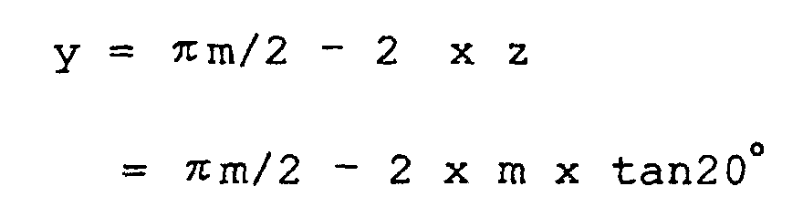
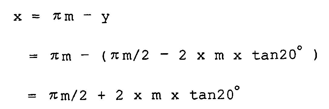
A direction w in which external force that is pushing
force on the surface in which each addendum of the rack portion
85a comes in contact with the input portion 56b1 acts is set
to be longer than an addendum distance x of the rack portion
95a that is the same as the addendum distance x of the gear portion
60a of the operated portion 60 provided on the rotary member
14 so as to rotate the rotary member 14. As described above,
when the length w of the input portion 56b1 at its direction
in which external force acts is set to be longer than the addendum
distance x of the rack portion 95a, it is possible to prevent
the disk cartridge from being broken when the disk cartridge
is caught with addendums of the rack portion 95a. A relationship
between the length w of this input portion 56b1 and the addendum
distance x of the rack portion 95a will be described in detail
with reference to FIG. 41 later on.
The lock arm 56c and the resilient arm 56d of the lock
member 56 have a clearance of a proper size formed therebetween.
The resilient arm 56d is given resilience of proper strength.
Then, the lock arm 56c has a lock claw 56c1 provided at its tip
end and the resilient arm 56d has a support head portion 56d1
provided at its tip end. The lock claw 56c1 of the lock arm 56
is formed of a wedge-like concave portion that protrudes in the
direction opposite to the input portion 56b1. This lock claw
56c1 has a protrusion 56c2 protruded from its one side to the
direction in which the hole of the rotary shaft portion 56a is
extended. A support head portion 56d1 of the resilient arm 56d
is cylindrical in shape and this support head portion 56d1 is
brought in contact with the lower front edge portion 15a of the
lower shell 15.
The lock member 56 having the above-mentioned
arrangement is attached to the support shaft 58 in the state
shown in FIGS. 32 to 40. Specifically, in the state in which
the lock claw 56c1 is directed toward the side of the lower concave
portion 16b, the rotary shaft portion 56a is fitted into the
support shaft 58 and the support head portion 56d1 of the resilient
arm 56d is brought in contact with the inner surface of the lower
front edge portion 15a. As a consequence, the lock arm 56c is
inwardly spring-biased under spring force of the resilient arm
56d, whereby the lock claw 56c1 at the tip end of the lock arm
is protruded into the lower concave portion 16b. At the same
time, the input portion 56b1 of the operation arm 56b is inserted
into the opening hole 57 from the inside and the tip end of the
input portion 56b1 is projected into the loading guide groove
53.
The lock member 56 that is the above-mentioned spring
member may be suitably made of polyacetal (POM) , for example.
It is needless to say that other engineering plastics can be
applied to the lock member and that a metal spring member can
be used as the material of the lock member. The lock member 56
is not limited to the shape of this embodiment and shape, layout
and so forth of the lock member can be selected properly so long
as it includes the operation arm 56b, the lock arm 56c and the
resilient arm 56d. Conversely, the support shaft 58 may be
provided on the upper shell 13 so that it can be supported to
the side of the upper shell so as to become freely rotatable.
Further, half support shafts may be protruded from both shells
and two support shafts may support the lock member 56.
The rotary member 14 that is made freely rotatable
within the upper and lower concave portions 16a, 16b of the upper
shell 13 and the lower shell 15 has the arrangement shown in
FIGS. 1, 2, 7 and 8. This rotary member 14 has a flat surface
portion 14a formed of a disk-like thin plate member and a ring
portion 14b continued to the outer peripheral edge of this flat
surface portion 14a. The inside opening portion 18 is formed
on the flat surface portion 14a of this rotary member 14. This
inside opening portion 18 is substantially equal to the outside
opening portion 17 of the lower shell 15 in shape and in size.
Specifically, similarly to the outside opening
portion 17, the inside opening portion 18 also includes a table
opening portion 18a set at the central portion of the flat surface
portion 14a and into and from which the turntable is inserted
and ej ected and a head opening portion 18b continued to the table
opening portion 18a and into and from which the optical head
is inserted and ejected. Then, the table opening portion 18a
of the flat surface portion 14a has the support edge portion
14c provided at its inner peripheral edge to support the inside
non-recording area of the optical disk 11 from the underside
in the free condition.
At one portion of the outer peripheral surface of the
ring portion 14b of the rotary member 14, there is provided an
operated portion 60 that is engaged with the rotary member by
the shutter opening and closing means to rotate the rotary member
14 within a predetermined angular extent when the shutter opening
and closing means is moved in a reciprocation fashion. As shown
in FIGS. 7, 8 and the like, this operated portion 60 includes
a gear portion 60a having a large number of gear teeth formed
over the circumferential direction in a predetermined angular
extent (approximately 30° ), a front slide portion 60b continued
to one side of this gear portion 60a, a rear slide portion 60c
continued to the other side of the gear portion 60a, a first
land portion 60d provided at the position distant from the gear
portion 60a in the circumferential direction by a predetermined
distance and a second land portion 60e provided at the position
distant from the front slide portion 60b in the circumferential
direction by a predetermined distance.
An inclined surface portion 60f whose height on the
side of the rear slideportion 60c is decreased is provided between
the rear slide portion 60c and the first land portion 60d of
the operated portion 60. The outer peripheral surface of the
front slide portion 60b of the operated portion 60 is
substantially the same as the addendum circle of the gear portion
60a in height, and the outer peripheral surface of the rear slide
portion 60c is substantially the same as the bottom circle of
the gear portion in height. Then, one side of the inclined surface
portion 60f is set to be substantially as high as the rear slide
portion 60c, and the other side is linearly extended like a tangent
and is reached to the top surface of the first land portion 60d.
Further, the front slide portion 60b has an initial operation
concave portion 61a formed of a recess having an arc-like
cross-section provided at its approximately central portion of
the circumferential direction, and the rear slide portion 60c
and the inclined surface portion 60f have a set position concave
portion 61b formed of a recess having a trapezoidal cross-section
provided therebetween.
Since the gear portion 60a and the front and rear slide
portions 60b, 60c of this operated portion 60 are protruded from
the outerperipheral surface of the ringportion 14b to the outside,
an upper escape portion 52a and a lower escape portion 52b are
provided on the corresponding portions of the upper shell 13
and the lower shell 15 so as to avoid them from contacting with
these protruded portions and to allow them to pass therein as
shown in FIGS. 4 and 15. The upper and lower escape portions
52a, 52b constitute the opening window 52. Then, a second
engagement portion that is engaged by the lock claw 56c1 of the
lock member 56 is constructed at the position in which the opening
portions 17, 18 are closed by the set position concave portion
61b.
The end portion on the opposite side of the gear portion
60a of the front slide portion 60b comprises an end stopper 63a
of the opening side, the end portion on the opposite side of
the inclined surface portion 60f of the first land portion 60d
comprises a first end stopper 63b of the closing side and the
end portion opposing the end stopper 63a of the second landportion
60e comprises a second end stopper 63a of the closing side. Then,
the first end stopper 63b comprises a first engagement portion
that is engaged by the lock claw 56c1 of the lock member 56 at
the opening position in which the opening portions 17, 18 are
opened.
Thus, the lower shell 15, the rotary member 14 and
the lock member 56 are placed in the following positional
relationship upon assembly-process. As shown in FIGS. 32 and
33, in the shutter closed state in which the outside opening
portion 17 of the lower shell 15 and the inside opening portion
18 of the rotary member 14 are rotated and displaced most largely,
the front slide portion 60b of the operated portion 60 is opposed
to the opening window 52 of the cartridge housing 12 and the
first end stopper 63b of the first land portion 60d is brought
in contact with the opening end 40a of the lower shell 15. At
that time, the second end stopper 63c of the second land portion
60e is opposed to the positioning portion 40b of the lower shell
15. The lock claw 56c1 of the lock member 56 is engaged with
the set position concave portion (second engagement portion)
61b of the rotary member 14, and the rotary member 14 is being
locked by this lock member 56.
In this state, when the rotary member 14 is released
from being locked by the lock member 56 and is rotated in the
predetermined direction by a predetermined angle, the inside
opening portion 18 agrees with the outside opening portion 17
and hence the two outside and inside opening portions 17, 18
are opened a great deal. As a result, the disk housing portion
16 is opened through the two outside and inside opening portions
17, 18 to expose a part of the information recording surface
of the optical disk 11. At that time, the end stopper 63a of
the front slide portion 60b contacts with the positioning portion
40b of the lower shell 15 to prevent the rotary member 14 from
being rotated more. The set position concave portion 61b is
opposed to the opening window 52 and the lock claw 56c1 of the
lock member 56 is engaged with the first end stopper 63b, whereby
the rotary member 14 is held in the locked state.
Arc-like cam protrusions 64 which are disposed at two
places in the circumferential direction are provided on the end
face of the opening side of the ring portion 14b of the rotary
member 14. These cam protrusions 64 are engaged with the cam
grooves of the upper shell 13 when the rotarymember 14 is assembled
with the upper shell 13 and the like. Then, when the rotary member
14 is rotated a predetermined angle, the respective cam
protrusions 64 are slid over the cam portions 22a of the cam
grooves 22, whereby the rotary member 14 is urged against the
side of lower shell 15.
This rotary member 14 has a pair of support shafts
14d, 14d provided at its flat surface portion 14a to support
a pair of shutter members 19a, 19a such that the shutter members
can be freely rotated in the plane direction of the flat surface
portion 14a. A pair of support shafts 14d, 14d forms supporting
points corresponding to a pair of shutter members 19a, 19b and
is disposed about the center of the table opening portion 18a
in a point symmetry fashion so that one of the support shafts
may be located at the edge portion of the head opening portion
18b.
A pair of shutter members 19a, 19b consisting the
shutter mechanism 19 attached to the rotary member 14 through
a pair of support shafts 14d, 14e is comprised of the two shutter
members 19a, 19b which are the same in shape and in size. A pair
of shutter members 19a, 19b has a shape and a structure shown
in FIGS. 9, 10 and so forth. Specifically, a pair of shutter
members 19a, 19b is formed of an approximately semicircular thin
plate member.
Bearing holes 65a are formed on the respective shutter
members 19a, 19b at their one side portions of the chord sides.
Apairof support shafts 14dis engaged with the respective bearing
holes 65a so as to become freely rotatable, respectively. When
the tip end portions of the respective support shafts 14d are
caulked, a pair of shutter members 19a, 19b is placed over the
flat surface portion 14a of the rotary member 14 and thereby
attached so as to turn freely. At that time, a pair of shutter
members 19a, 19b is attached in such a manner that their chord
sides may oppose to each other.
Stepped portions 66 having predetermined lengths in
the direction perpendicular to the chord lines are provided on
the chord sides of a pair of shutter members 19a, 19b. The stepped
portions 66 form a convex-side joint portion 66a and a
concave-side joint portion 66b at their respective sides. The
respective joint portions 66a, 66b have overhang portions 67a,
67b provided thereat so as to overhang in the directions
perpendicular to the directions in which the chords are extended.
As a consequence, in a pair of shutter members 19a, 19b, the
end face of the convex-side joint portion 66a and the end face
of the concave-side joint portion 66b are opposed to each other
with the result that the overhang portion 67a of the convex-side
j ointportion 66a and the overhangportion 67b of the concave-side
joint portion 66b are fastened together.
As shown in FIG. 16, a pair of shutter members 19a,
19b is attached to the rotary member 14 in such a manner that
their chord sides may be opposed to each other. Accordingly,
when a pair of shutter members 19a, 19b is rotated so as to be
detached from each other to the outside, the respective shutter
members 19a, 19b are moved on the flat surface portion 14a
outwardly, by which the inside opening portion 18 is opened
completely. On the other hand, a pair of shutter members 19a,
19b is rotated toward the inside to cause their joint portions
66a, 66b to contact with each other, whereby the shutter mechanism
19 is shaped in approximately circle. As a result, the central
portion of the inside opening portion 18 is completely closed
by a pair of shutter members 19a, 19b.
Further, the respective shutter members 19a, 19b have
open and close grooves 68 provided thereon to allow the shutter
members 19a, 19a to open and close the opening portions 17, 18
through the rotation movement of the rotary member 14. One ends
of the respective open and close grooves 68 are set at
substantially the central portions of the respective shutter
members 19a, 19b and the respective open and close grooves are
formed so as to be extended to the outside of prolonged lines
which connect one ends and the bearing holes 65a. At the outside
end portions of a pair of open and close grooves 68, there are
provided resilient members 69a which are formed by recessing
the above outside end portions and concave portions 69a which
are used to escape the operation convex portions 39a, 39b of
the lower shell 15. Corresponding operation convex portions of
a pair of operation convex portions 39a, 39b of the lower shell
15 are slidably engaged with a pair of open and close grooves
68.
Furthermore, a pair of shutter members 19a, 19b has
rib-escape grooves 70 that are shaped like concave grooves
corresponding to the ribs 37 serving as the ribs of the lower
shell 15 in the state in which the opening portions 17, 18 are
closed completely. Specifically, the rib-escape grooves 70 are
formed like substantially U-shaped grooves corresponding to the
arc-like rib portions 37a and a pair of linear rib portions 37b,
37b of the ribs 37. On the opposite sides of the rib-escape grooves,
there are provided flat-surface-like escape surfaces 70a
corresponding to the symmetrical rib portions 37c, 37c. The
rib-escape grooves 70 and the ribs 37 constitute a labyrinth-like
dust-proof clearance 71 having a crank-like shape as shown in
FIG. 21.
This dust-proof clearance 71 has the above
labyrinth-like clearance to prevent dusts and smudges from
entering the disk compartment. The dust-proof clearance 71 is
formed when the rotary member 14 is rotated in predetermined
direction to allow a pair of shuttermembers 19a, 19b to completely
close the opening portions 17, 18. The labyrinth-like clearance
having the crank-like shape is formed at the j oint surface between
a pair of shutter members 19a, 19b and the lower shell 15, whereby
dusts and smudges can be prevented from passing thereto without
difficulty. Thus, dusts and smudges can be prevented or
effectively suppressed from entering the disk compartment 16.
Conversely, the above-mentioned ribs may be provided
on a pair of shutter members and corresponding rib-escape grooves
may be provided on the lower shell with similar effects being
achieved. Although a clearance is set between the outer
peripheral edge and the shutter members 19a, 19b on the side
of the flat surface portion 14a of the rotary member 14, since
such clearance is closed by a shielding portion 38a provided
on the lower shell 15 , it is possible to prevent dusts and smudges
from entering into the disk compartment from the above clearance.
A pair of shutter members 19a, 19b having the
above-mentioned arrangement is assembled on the rotary member
14 with a predetermined positional relationship such that a pair
of shutter members can open and close the inside opening portion
18 as shown in FIG. 16. Then, the rotary member 14 having a pair
of shutter members 19a, 19b is assembled with a predetermined
positional relationship relative to the upper and lower shells
13, 15 as shown in FIG. 20.
Specifically, when the cartridge housing 12 is
assembled, the upper and lower shells are fastened together in
such a manner that the inside opening portion 18 of the rotary
member 14 may oppose to the outside opening portion 17 of the
lower shell 15. At that time, of the operated portions 60 of
the rotary member 14, the front slide portion 60b continued to
one side of the gear portion 60a is disposed on the opening window
52 of the cartridge housing 12, whereby the initial operation
concave portion 61a is disposed at substantially the central
portion of the opening window 52. This rotary member 14 and the
upper shell 13 constitute the disk compartment 16 formed of a
circular space portion.
This disk compartment 16 accommodates therein the
optical disk 11, which shows a concrete example of the disk-like
recording medium, in such a manner that the optical disk can
be freely rotated with predetermined clearances in the outside
of the radius direction and in the thickness direction. At that
time, when the optical disk 11 is of the single side recording
system in which an information recording surface is formed on
only one side, the optical disk is accommodated within the disk
compartment in such a fashion that the information recording
surface thereof may be opposed to the opening portions 17, 18.
As a result, a label attachment surface, which is the other surface
of the optical disk 11, is set on the side of the upper shell
13 and the chucking ring 33 is opposed to the central center
hole 11a.
The optical disk 11 is formed of a thin disk-like
recording member having the center hole 11a bored at its central
portion. The turntable 81 of the table drive apparatus 78 housed
within the disk recording and reproducing apparatus is fitted
into the center hole 11a of the optical disk 11 as shown in FIG.
22. The chucking ring 33 is attracted by magnetic force of the
magnet 97 incorporated within this turntable 81 and the optical
disk 11 is held by the chucking ring 33 and the turntable 81
and thereby formed as one body in the rotation direction. Then,
the turntable 81 and the optical disk 11 may be rotated together
at a predetermined speed (e.g. constant linear velocity) by
driving the spindle motor 75 to which the turntable 81 is attached.
Synthetic resins such as ABS resin
(acrylonitrile-butadiene-styrene resin) and HIPS (high impact
polystyrene resin) , for example, may be suitable as materials
of the upper shell 13, the rotary member 14, the lower shell
15, the shutter the members 19a, 19b, the mis-erase prevention
member 25 and the ring holder 34.
However, it is needless to say that other engineering
plastics may also be used suitably and that other metal materials
such as aluminum alloy and stainless steel can also be used
suitably. A material of the chucking ring 33 is not limited to
the above-mentioned stainless steel, and not only metals such
as iron and other magnetic materials but also magnetic materials
in which plastics have contained magnetic materials can be
applied to the material of the chucking ring.
The disk recording medium device 10 having the
aforementioned arrangement canbe assembledwith ease as follows.
The assembly work of this disk recording medium device 10 is
carried out in the state in which the upper shell 13 is faced
downward. First, the optical disk 11 is set within the upper
concave portion 16a of the upper shell 13. At that time, the
optical disk 11 is inserted into the upper concave portion 16a
in the state in which the information recording surface is faced
downward.
Next, the opening side of the rotary member 14 is fitted
into the upper concave portion 16a in such a manner as to cover
the optical disk 11, whereby the optical disk 11 is rotatably
accommodated within the disk compartment 16 formed of the rotary
member 14 and the upper shell 13. At that time, the direction
in which the inside opening portion 18 of the rotary member 14
is extended is made coincident with the front and rear direction
of the upper shell 13 and the front slide portion 60b of the
operated portion 60 is faced to the opening window 52.
It is desired that the shutter mechanism 19 should
be assembled to the rotary member 14 in advance. In that case,
the chord sides of a pair of shutter members 19a, 19b are opposed
to each other, and the respective bearing holes 65a are fitted
into the respective support shafts 14d of the rotary member 14,
thereby the shutter members being set on the flat surface portion
14a. Then, the tip end portions of the respective support shafts
14d are caulked to allow a pair of shutter members 19a, 19b to
be attached to the flat surface portion 14a in such a manner
that a pair of shutter members can open and close the inside
opening portion 18.
Next, the lock member 56 is attached to the support
shaft 58 of the lock housing portion 55. At that time, the support
head portion 56d1 of the resilient arm 56d of the lock member
56 is brought in contact with the inner surface of the upper
front edge portion 13a of the upper shell 13 and the input portion
56b1 of the operation arm 56b is protruded into the loading guide
groove 53 from the opening hole 57 of the cartridge housing 12
under spring force of the resilient arm 56d. Then, the lock claw
56c1 of the lock arm 56c of the lock member 56 is engaged with
the set position concave portion 61b of the operated portion
60. As a result, the rotary member 14 is locked by the lock member
56.
At the same time or before and after the rotary member
is locked by the lock member, the mis-erase prevention member
25 is attached to the plug housing portion 26. In this case,
the mis-erase prevention member is inserted from the side of
the guide protrusion 25c, the engagement portion 25d is engaged
with the guide portion 29 and the operation protrusion 25b is
engaged with the lower recess 27b of the opening window 27.
Next, the lower shell 15 is laid over the rotary member
14 including the shutter mechanism 19 and this lower shell 15
is combined to the upper shell 13. At that time, the opening
end 40a of the lower shell 15 is fitted into the first concave
portion 23a of the upper shell 13, and the positioning portion
40b of the lower shell 15 is fitted into the concave portion
23b of the upper shell 13. At the same time, the respective
positioning shaft portions 46a, 46b of the lower shell 15 are
fitted into the respective escape portions 49a, 49b of the upper
shell 13. Then, the reference protrusions 47 provided on the
respective positioning shaft portions 46a, 46b are fitted into
the respective reference holes 48 of the upper shell 13, whereby
the lower shell 15 may be properly positioned to the upper shell
13 automatically.
At that time, if a pair of shutter members 19a, 19b
is set in the state shown in FIG. 16, then a pair of operation
convex portions 39a, 39b provided within the lower concave
portion 16b of the lower shell 15 can be respectively opposed
to the concave portions 69b of the open and close grooves 68
provided on the respective shutter members 19a, 19b. As a result,
regardless of the exact positions of a pair of open and close
grooves 68, a pair of operation convex portions 39a, 39b can
be engaged with a pair of open and close grooves 68, 68 with
ease only by combining the lower shell 15 with the upper shell
13 together.
Thereafter, by the use of a plurality of stationary
screws, the lower shell 15 can be fastened and fixed to the upper
shell 13, whereby the assembly work of the disk recording medium
device 10 having the outside appearance and shape shown in FIG.
17 and which has the cross-sectional arrangement shown in FIG.
20 is completed.
In this case, without using a fixing means consisting
of separatemembers such as stationary screws, the joint surfaces
of the upper shell 13 and the lower shell 15 can be directly
bonded together by a suitable means such as an adhesive agent.
As described above, according to the disk recording medium device
10 of this embodiment, the number of used assemblies is relatively
small and the assembly work can be carried out with ease.
Although not shown, if the cartridge housing is
provided with an opening portion of size corresponding to two
of the above-mentioned opening portions 17, 18, then the disk
recording medium device becomes able to use two optical heads
simultaneously. In this case, the opening portions of size
corresponding to two opening portions may be disposed at a right
angle and thereby shaped as an L-like opening portion.
Alternatively, the above-mentioned opening portions of size
corresponding to two opening portions may be disposed on a
straight line in an opposing relation to each other and thereby
shaped as an I-like opening portion.
In this case, if the rotary member 14 and the lower
shell 15 for use with one head are used instead of the rotary
member and the lower shell for use with two heads, then while
a new information signal is being recorded by one optical head,
an information signal that has been just recorded by the other
optical head can be processed in such various manners as to confirm
the recorded state of the information signal. If the rotary
members and the lower shells are exchanged with each other for
one head or two heads, then the manufacturing process of the
disk recording medium device can cope with the manufacturing
process for use in one head and the manufacturing process for
use in two heads with ease. Thus, the manufacturing and assembly
lines can be made common and hence the disk recording medium
device according to the present invention can properly meet the
needs of users.
According to the disk recordingmediumdevice 10 having
the aforementioned arrangement, the rotary member 14 can be
rotated by small force, accordingly, a pair of shutter members
19a, 19b can be opened and closed by small drive force. Inaddition,
the rotary member 14 can generate resistance to impacts and
vibrations inputted from the outside so that a pair of shutter
members 19a, 19b may become difficult to open.
The disk recording medium device 10 can be used by
a disk recording and reproducing apparatus 73 which shows a
concrete example of the disk recording and/or reproducing
apparatus having the arrangement shown in FIG. 26, for example.
The disk recording and reproducing apparatus 73
includes the tape drive apparatus 78 to chuck and rotate the
optical disk 11 and the optical pickup device 79 to read an
information signal from the optical disk and to write an
information signal on the optical disk by radiating laser beams
on the information recording surface of the optical disk 11 and
is mounted on a chassis 74.
The chassis 74 is shaped like a flat surface having
approximately a square shape and includes a reinforcement rib
74a that is obtained by continuously bending the peripheral edge
of the chassis upward. The reinforcement rib 74 includes support
protrusions 74b provided at its four positions to support the
chassis 74 to the members on the side of the apparatus body shown
in FIGS. 29 and 30.
A motor base plate 76 having the spindle motor 75
mounted thereon is fixed to approximately the central portion
of the chassis 74 by a fixing means such as stationary screws.
A first opening portion 77a and a second opening portion 77b,
both of which are shaped like squares, are provided on the chassis
74 at its respective sides of the longitudinal directions across
the spindle motor 75. The table drive apparatus 78 is attached
in association with the first opening portion 77a. The second
opening portion 77b is used to attach another table drive
apparatus, not shown.
The disk recording and reproducing apparatus 73
consists of the table drive apparatus 78 for rotating the optical
disk 11 at a predetermined speed (e. g. constant linear velocity) ,
the optical pickup device 79 which shows a concrete example of
a pickup device for writing an information signal on the optical
disk and for reading an information signal from the optical disk
and a pickup movement apparatus 80 for moving this optical pickup
device 79 close to or away from the table drive apparatus 78
and so forth.
The table drive apparatus 78 is comprised of the
spindle motor 75, the turntable 81 integrally provided at the
rotationportion of this spindlemotor 75 and the like. The spindle
motor 75 is attached onto the motor base plate 76 made of a thin
plate metal, and a flexible wiring plate 76a is fixed to the
upper surface of the motor base plate 76 by a fixing means such
as an adhesive agent. Then, wiring of the spindle motor 75 and
wiring of a table drive connector are connected to the wiring
circuit of the flexible wiring plate 76a. Further, a plurality
of flexible wiring plates 76b are fixed to the connector.
As shown in FIGS. 21, 22 and the like, the spindle
motor 75 includes a fixed portion 75a fixed to the motor base
plate 76 and a rotary portion 75b rotatably supported by this
fixed portion 75a. The turntable 81 is integrally provided with
a rotary shaft that serves as a rotation center of the rotary
portion 75b. The turntable 81 includes a fitted portion 81a fitted
into the center hole 11a of the optical disk 11 and a table portion
81b disposed at the lower portion of this fitted portion 81a
and on which the peripheral edge portion of the center hole 11a
is held and the like. Then, the fitted portion 81a houses therein
the magnet 97. The chucking ring 33 is opposed to this turntable
81 and the optical disk 11 set on the table portion 81b is held
under attraction force of the chucking ring 33 attracted by the
magnet 97, whereby the optical disk 11 can be chucked and rotated
in unison with the turntable 81.
As shown in FIG. 26, a pair of guide shafts 82a, 82b
is disposed in parallel to each other so as to sandwich the spindle
motor 75 from both sides. A pair of guide shafts 82a, 82b is
formed of a round bar-like member whose outer peripheral surface
is made smooth. Then, the first guide shaft 82a is supported
at its respective ends by an adjustment plate 83. The second
guide shaft 82b is supported at its respective ends by the chassis
74.
The adjustment plate 83 is attached to the chassis
74 in such a manner that its attitude can be changed. By changing
the attitude of the adjustment plate 83, it becomes possible
to adjust degree of parallelism between a pair of guide shafts
82a and 82b. By a pair of guide shafts 82a, 82b, the optical
pickup device 79 is supported so as to move close to or away
from the turntable 81. One end portions of a pair of guide shafts
82a, 82b are disposed at both sides of the spindle motor 75 and
the other end portions are made parallel to each other and extended
in the direction in which they are moving away from the spindle
motor 75.
The optical pickup device 79 comprises a slide member
84 guided and slid by a pair of guide shafts 82a, 82b, an optical
head set on this slide member 84 and which can be moved back
and forth in a reciprocation fashion and the like. The slide
member 84 is large enough to cross a pair of guide shafts 82a,
82b and is formed as a block-like shape in order to increase
rigidity. A pair of bearing portions 84a is provided at one side
of the longitudinal direction of this slide member 84 in the
width direction crossing the longitudinal direction. The first
guide shaft 82a is slidably inserted into these bearing portions
84a. Further, on the other side of the longitudinal direction
of the slide member 84, there is provided an insertion hole,
not shown, into which the second guide shaft 82b is inserted
slidably. This insertion hole is larger than the diameter of
the second guide shaft 82b and hence the slide member 84 can
be rotated about the first guide shaft 82a so that the slide
member can be inclined an amount corresponding to such clearance
in the upper and lower direction.
The optical head of the optical pickup device 79
includes a biaxial actuator having an objective lens 79a, an
optical control unit having a semiconductor laser, a
photo-electric conversion element or the like for recording and
reproducing an information signal through this biaxial actuator
and so forth. Most of the biaxial actuator is covered with a
head cover 79b and the objective lens 79a is exposed from an
opening portion formed on this head cover 79b. This objective
lens 79a is opposed to the information recording surface of the
optical disk 11 set onto the turntable 81.
Of a pair of guide shafts 82a, 82b, the first guide
shaft 82a is supported by a pair of shaft support members 83a,
83a provided on the adjustment plate 83. The respective shaft
support members 83a are provided with a pair of shaft presser
plates 83b and the first guide shaft 82a is fixedly supported
by fixing these shaft presser plates with screws 83c. The second
guide shaft 82b is supported by a pair of shaft support members
74c, 74c provided on the chassis 74 and fixedly supported by
screwing with fixing screws 74e. Then, a feed screw drive device
98 serving as a pickup movement device is attached to the
adjustment plate 83.
The feed screw drive device 98 is comprised of a feed
screw 85, a feedmotor 86, a support plate 87 , a power transmission
member 88 and the like as shown in FIG. 27 in an enlarged-scale.
The feed screw 85 is obtained by forming a streak of screw groove
85a, which is spirally extended, on an outer circumference
surface of a round bar slightly shorter than the guide shafts
82a, 82b along substantially the whole length of the axis
direction. A trapezoid shape whose cross-section is trapezoid
having slight inclination angles on both side surfaces of the
groove may be suitable as the screw shape of this feed screw
85 and a square thread whose cross-section forms a square may
be suitable as the above-mentioned screw shape of the feed screw.
Moreover, a semicircular thread whose cross-section forms a
semicircle may be applied to the above-mentioned screw shape
of the feed screw, and other screws of well-known shapes can
be applied to the above-mentioned screw shape of the feed screw.
The feed screw 85 may serve as a rotary shaft of the
feed motor 86, which is a drive source, as well. The feed screw
is directly rotatedby the feedmotor 86. The feedmotor 86 includes
a cylindrical motor case 86a and a case cover 86b that closes
one opening portion of the motor case 86a. The motor case 86a
is fixed to a motor supporting member 87a of a support plate
87 by a fixing means such as caulking and thereby configured
integrally therewith. A coil portion that is wound in an annular
fashion is fitted into and fixed to the inner peripheral surface
of this motor case 86a and an annular magnet is fitted into the
inside of the coil portion by a fixing means such as insertion
with pressure.
The support plate 87 is formed of a long and slender
plate material made of plate metal having approximately the same
length as that of the feed screw 85a. The support plate 87 has
a motor support member 87a and a screw support member 87b provided
at its respective ends in the longitudinal direction, and the
motor support member and the screw support member are opposed
to each other when they are erected in the same direction. The
motor support member 87a has an aperture 88a bored at its central
portion and has also a fitting aperture 88b bored at its height
position corresponding to the aperture 88a in the upper portion
of the screw support member 87b. The feed motor 86 is fixed to
the outer surface of the motor support member 87a and the feed
screw 85 is inserted into the aperture 88a. Then, a tip end portion
of the feed screw 85 is supported by a bearing member, which
is fitted into and fixed to the fitting aperture 88b, so as to
become freely rotatable.
The support plate 87 has a guide rib 87c that is one
side of the support plate obtained after one side of the width
direction of the support plate has been continuously erected
along the longitudinal direction. This guide rib 87c is disposed
substantially just under the feed screw 85 and is also extended
in substantially parallel to the axis line of the feed screw
85. Further, the support plate 87 has two insertion apertures
87d and two positioning apertures 87e defined therein. The two
positioning apertures 87e are used to properly locate the support
plate 87 at predetermined position, and the support plate is
attached to the adjustment plate 83 by attachment screws 89a
inserted into the insertion apertures 87d.
A feed nut 90, which shows a concrete example of a
power transmission member, is used to convert rotation force
of the feed screw 85 into rectilinear motion and to transmit
the rectilinear motion to the slide member 84. The feed nut is
composed of a first nut member 90a and a second nut member 90b
and a coil spring 90c for spring-biasing the two nut members
90a, 90b in the direction in which they are moved away from each
other.
The first nut member 90a includes a nut body shaped
like a block and a cylindrical cylinder shaft portion continued
to one surface side of this nut body and has also at its one
side of the axial direction aperture extending through the nut
body and the cylinder shaft portion a first screw portion 90a1
that is screwed with the screw groove 85a of the feed screw 85.
Further, the first nut member 90a is provided with a protrusion
portion 90a2 that is protruded in the lateral direction
perpendicular to the axis direction. This protrusion portion
90a2 has a slit extended in the direction in which the cylinder
shaft portion is extended. The guide rib 87c of the support plate
87 is engaged with this slit so as to become freely slidable.
The second nut member 90b is formed of a sleeve-like cylindrical
member and has an axis direction aperture bored at its central
portion. The axis direction aperture has a second screw portion
90b1 formed at one side thereof to be screwed into the screw
groove 85a of the feed screw 85. Further, the axis direction
aperture has a fitting aperture into which the cylindrical shaft
portion of the first nut member 90a is fitted detachably. This
fitting aperture has a key-like protrusion that is protruded
in the inside of the radius direction. The coil spring 90c is
interposed between the second nut member 90b and the first nut
member 90a. Under spring force of this coil spring, a pair of
nut members 90a and 90b is spring-biased in the direction in
which the nut members are made distant from each other to thereby
absorb axis-direction fluctuations generated between the feed
nut 90 and the feed screw 85.
The first and second nut members 90a, 90b having the
above-mentioned arrangements and the coil spring 90c are
integrally combined and assembled on the feed screw 85. The
assembly work of the first and second nut members and the coil
spring will be described below, for example. First, after the
coil spring 90c had been inserted into the cylinder shaft portion
of the first nut member 90a, the cylinder shaft portion is fitted
into the fitting aperture of the cylinder shaft portion of the
second nut member 90b. Next, the feed screw 85 is inserted into
the feed nut 90 where the two nut members 90a, 90b had been
assembled.
In this case, the coil spring 90c is slightly
contracted by moving the two nut members 90a, 90b close to each
other. In the state in which this compressed state is being held,
the feed screw 85 is turned and inserted into the feed nut 90.
As a result, the thread portion of the first nut member 90a is
meshed with the screw groove 85a of the feed screw 85 and the
thread portion of the second nut member 90b is simultaneously
meshed with the screw groove 85a. As a result, under spring force
of the coil spring 90c, the first nut member 90a is spring-biased
in the direction in which it is moved away from the feed motor
86, whereby the second nut member 90b is spring-biased in the
direction in which it is moved close to the feed motor 86.
As a result, in the screw portion of the first nut
member 90a, the thread surface of the left-hand side shown in
FIG. 27 is urged against the left-hand side thread surface of
the feed screw 85 so that a clearance is produced between the
right-hand side thread surface and the left-hand side thread
surface. Similarly, in the thread portion of the second nut
portion 90b, the thread surface of the right-hand side shown
in the sheet of drawing is urged against the right-hand side
thread surface of the feed screw 85 so that a clearance is produced
between the left-hand side thread surface and the right-hand
side thread surface. As a result, a clearance on the whole of
the feed nut 90 can be removed and hence fluctuations between
the feed nut and the feed screw 85 can be absorbed. Then, since
the slit provided on the protruded portion 90a2 of the first
nut member 90a is engaged with the guide rib 87c of the support
plate 87, the feed nut 90 can be linearly moved to the axis
direction of the feed screw 85.
Further, the first nut member 90a is provided with
a drive protrusion 90d that protrudes in the lateral direction.
This drive protrusion 90d is engaged with a protrusion reception
member 91 secured to the slide member 84, and movement force
of the feed unit 90 is transmitted through this protrusion
reception member 91 to the slide member 84. The protrusion
reception member 91 includes a fixing member 91a for fixing the
protrusion reception member to the slide member 84, a support
member 91b continued to this fixing member 91a and a resilient
member 91c continued to the support member 91b.
The fixing member 91a is formed of a long and slender
plate member and includes the L-like support member 91b provided
at its one side of the width direction in somewhere of the
longitudinal direction. Then, the support member 91b includes
a support portion 91d formed of a recess provided at its tip
end corner portion of the free end side to receive and support
the drive protrusion 90d. The resilient member 91c has resiliency
of proper strength given by two corner portions formed of a bent
triangle, and a bent portion at the tip end is formed as a presser
portion 91e and opposed to the support portion 91d. Further,
the fixing member 91a has a plurality of insertion apertures
to attach the protrusion reception member 91 to the slide member
84 and the protrusion reception member 91 is attached by a fixing
means such as fixing screws.
The drive protrusion 90d of the feed nut 90 attached
to the feed screw 80 is inserted into a clearance between the
support portion 91d of the protrusion reception member 91 thus
attached and the presser portion 91e. Then, the drive protrusion
90d is held between the support portion 91d and the presser portion
91e under spring force of the resilient member 91c, whereby force
can be transmitted to the feed nut 90 and the slide member 84.
A stainless steel plate may be suitably used as
materials of the adjustment plate 83 and the support plate 87,
for example. It is needless to say that a steel plate and other
metal plates may also be used suitably as the materials of the
adjustment plate and the support plate and that engineering
plastics having large strength may also be used suitably as the
materials of the adjustment plate and the support plate. Further,
metal materials such as stainless steel that is difficult to
gather rust and which has sufficiently large strength may be
suitably used as a material of the feed screw 85. Furthermore,
a stainless steel plate having large strength may also be suitably
used as a material of the protrusion reception member 91 and
other plate materials also may be used as the material of the
protrusion reception member.
The aforementioned pair of guide shafts 82a, 82b, the
adjustment plate 83 and the feed screw drive apparatus 98
constitute the pickup movement apparatus that can move the
optical pickup device 79 close to or away from the turntable
81. Next, a recording and reproducing apparatus body 92 of the
disk recording and reproducing apparatus 73 will be described.
FIG. 28 shows a concrete example of the recording and reproducing
apparatus body 92. The recording and reproducing apparatus body
is comprised of the following constituents. Specifically, the
recording and reproducing apparatus body 92 includes three
control apparatus of a system controller S1, a memory controller
S5 and a drive controller D1.
The system controller S1 and the memory controller
S5 are directly connected and the connected line therebetween
is connected to a read-only memory device (ROM) S2 and a
random-access memory device (RAM) S3. Further, the memory
controller S5 is connected with a memory S4, an encoder S6 for
MPEG2 (movingpicture compression system applied to the existing
television broadcasting that corresponds to 3M to 40 Mbps, HDTV
and a broadband ISDN) and an MPEG2 decoder S7. Furthermore, the
system controller S1 is connected with a control panel S8 and
a remote control reception unit S9.
The drive controller D1 is connected with an
error-correction processing circuit (ECC) D4 and the connected
line therebetween is connected with a memory device (ROM) D2,
a memory device (RAM) D3, a servo circuit D6 and an address decoder
D7. Further, the drive controller D1 is connected with a recording
error j udgment circuit D8 for judging whether or not error occurs
in the recording mode. This drive controller D1 is connected
through a command interface to the system controller S1.
The correction processing circuit D4 is connected
through a data interface to the memory controller S5 and is also
connected to a modem circuit D5. Then, the modem circuit D5 is
connected to the optical head including the objective lens 79a
of the optical pickup device 79. Further, the servo circuit D6
is connected to the spindle motor 75, the optical pickup device
79 and the recording error judgment circuit D8. Then, the optical
pickup device 79 is connected to an address decoder D7, and the
address decoder D7 is connected to the recording error judgment
circuit D8.
The recording and reproducing apparatus body 92 having
the above-mentioned arrangement is accommodated within an armor
case 93 formed of a hollow housing shown in FIGS. 29 and 30,
for example, and is used as a constituent of the disk recording
and reproducing apparatus 73. The armor case 93 includes a case
body 93a that is opened to the upper surface and the front surface,
a case lid 93b detachably attached to the upper portion so as
to close the upper surface of the case body 93a, a front panel
93c detachably attached to the front portion so as to close the
front surfaces of the case body 93a and the case lid 93b and
so forth. The disk recording and reproducing apparatus 73
including the recording and reproducing apparatus body 92, the
above-mentioned table drive apparatus 78 and so forth are
accommodated within this armor case 93.
The case body 93a of the armor case 93 has leg members
93d provided at its four portions to proj ect downward. The front
panel 93c of the armor case 93 is formed of an oblong plate member
and has an oblong cartridge entrance and exit slot 94 provided
at its upper portion. The cartridge entrance and exit slot 94
has approximately the same size as that of the front surface
side of the disk recording medium device 10. This cartridge
entrance and exit slot 94 is constantly closed by an open and
close door 94a disposed in its inside.
The open and close door 94a is spring-biased in the
closing side under spring force of a spring, not shown. As shown
in FIG. 30, when the disk recording medium device 10 is inserted
into predetermined position by pressing the open and close door
94a at the front portion of the disk recording medium device,
the disk recording medium device 10 can be automatically loaded
onto the disk recording and reproducing apparatus body by a
loading mechanism, not shown. Then, the disk recording medium
device 10 that has been transported by the loading mechanism
is properly located at predetermined position within the armor
case 93 and fixed. At the same time or before and after the disk
recording medium device is properly located and fixed, the
shutter mechanism 19 of the disk recording medium device 10 is
opened by the shutter open and close means provided within the
armor case 93, whereby the inside and outside opening portions
17, 18 of the cartridge housing 12 are opened.
FIG. 31 shows a rack rod 95 that shows a concrete example
of this shutter open and close means. This rack rod 95 includes
a rack portion 95a meshed with the gear portion 60a of the operated
portion 60 of the rotary member 14, a front resilient member
95b provided at the tip end side of this rack portion 95a and
a rear resilient member 95c provided at the base end side of
the same rack portion 95a. The rack portion 95a of the rack rod
95 is formed of a straight rod material and is protruded at its
intermediate portion to one surface side. The rack portion has
gear teeth the number of which is approximately the same as that
of the gear portion 60a.
Assuming that the rack portion 95a of the rack rod
95 is shaped as shown in FIG. 41, for example, then the distance
x between adjacent addendums of the rack portion 95a and the
length w of the input portion 56b1 of the lock member 56 should
preferably have the following relationship.
m : module α : pressure angle (e.g. 20° ) x : addendum distance y : addendum size h : height of tooth (h = m) πm : pitch πm/2 : 1/2 of pitch
The pressure angle α is not limited to 20° and other
angles such as 14.5° can be applied to the pressure angle. The
addendum size
y is given by the following equation:
The addendum distance x is given by the following
equation:
Therefore, the length w of the input portion 56b1 is
set to be larger than x (addendum distance). Such size
relationship can be applied to the rack portion 95a of the rack
rod 95 and the input portion 56b1 of the lock member 56 with
the following effects being achieved, for example.
When the shutter opening and closing operations of
the disk cartridge of the above-described disk recording medium
device 10 are carried out by rack-like parts integrally formed
or composed of a plurality of assemblies, the lock mechanism
of the shutter mechanism is released by the rack-like parts.
At that case, when the length w of the input portion 56b1 for
releasing the lock mechanism is set to be larger (longer) than
the distance x between adjacent addendums of the rack portion
95a, the addendum of the rack portion 95a can constantly act
on the input portion 56b1. As a result, the input portion 56b1
can be constantly pressed by the addendum of the rack portion
95a, load fluctuations generated such as when the input portion
is caught with the addendum of the rack portion 95a can be
suppressed so that smooth shutter opening and closing operations
can be realized.
As a result, load fluctuations generated when the
shutter of the disk recording medium device 10 is opened and
closed by the table drive apparatus 78 can be suppressed reliably
without any special devices. Then, the input portion 56b1 can
be prevented from being caught with the addendum of the rack
portion 95a of the rack rod 95 and the disk cartridge can be
prevented from being broken when the input portion is caught
with the addendum.
The front resilient member 95b of the rack rod 95 is
extended in the same direction of the rack rod 95 and is made
resilient properly. An initial operation convex portion 96a is
provided at the tip end portion of the front resilient member.
Further, the rear resilient member 95c is similarly extended
in the same direction of the rack rod 95 and is made resilient
properly. A stopper convex portion 96b is provided at the tip
end portion of the rear resilient member. The initial operation
convex portion 96a and the stopper convex portion 96b are
protruded in the same direction as that of the gear teeth of
the rack portion 95a and these initial operation portion and
stopper convex portion are set on the same straight line.
Further, although the initial operation convex
portion 96a has an arc-like cross-section, the size and height
of the initial operation convex portion are approximately the
same as those of the gear teeth of the rack portion 95a. On the
other hand, although the stopper convex portion 96b has a
cross-section that is an angle form similarly to the gear teeth
of the rack portion 95a, the size and height of the cross-section
of the stopper convex portion are formed slightly larger. Then,
the front and rear resilientmembers 95b, 95c are given resiliency
of proper strength, whereby the initial operation convex portion
96a and the stopper convex portion 96b can be moved rearward
with resiliency. In FIG. 31, reference numeral 95d designates
a guide portion that serves as a reinforcement portion for use
with the rack rod 95 as well. This guide portion 95d is engaged
with the loading guide groove 53 of the disk recording medium
device 10.
The manner in which the rotary member 14 of the disk
recording medium device 10 is rotated, the shutter mechanism
19 is opened and closed and other members are operated in unison
with actions of the rack rod 95 having the above-mentioned
arrangement will be described with reference to FIGS. 29 and
30 and FIGS. 32 to 40.
As shown in FIG. 29, the inside and outside opening
portions 17, 18 of the disk recording medium device 10 are
completely closed by the shutter mechanism 19 until the disk
recording medium device is inserted into the cartridge entrance
and exit slot 94 of the armor case 93. In this state, as shown
in FIG. 30, when the disk recording medium device 10 is inserted
from the cartridge entrance and exit slot 94 of the armor case
93 into the disk recording and reproducing apparatus 73, the
lock member 56 is released from the locked state by the rack
rod 95 disposed within the armor case 93. Thereafter, the rack
rod 95 acts to open a pair of shutter members 19a, 19b to allow
the inside and outside opening portions 17, 18 to be opened,
thereby a part of the information recording surface of the optical
disk 11 being exposed.
First, as shown in FIGS. 30 and 32, when the disk
recording medium device 10 is inserted into the cartridge
entrance and exit slot 94 of the armor case 93 a predetermined
amount, the initial operation convex portion 96a of the rack
rod 95 is entered into the loading guide groove 53 formed on
one side surface portion of the disk recording medium device
10. As a result, the initial operation convex portion 96a inserts
the input portion 56b1 of the lock member 56 protruded in the
loading guide groove 53 into the lock housing portion 55 with
pressure against spring-biasing force of the resilient arm 56d.
Consequently, the lock member 56 is rotated about the
support shaft 58 to allow the lock claw 56c1 to be disengaged
from the set position concave portion 61b as shown in FIGS. 33
and 34. As a result, the rotary member 14 is released from the
locked state and thereby becomes able to rotate freely.
In this case, although the input portion 56b1 that
had been inserted into the opening hole 57 with pressure by the
initial operation convex portion 96a is protruded into the
loading guide groove 53 temporarily under spring force of the
resilient arm 56d, the input portion is inserted again into the
opening hole 57 with pressure by the teeth of the rack portion
95a continuing the initial operation convex portion 96a. The
inserted state of this input portion 56b1 is being continued
during a period in which the rack portion 95a is being opposed
to the input portion 56b1. At that time, since the length w of
the input portion 56b1 is larger than the distance x (= πm/2
+ 2 x m x tan20° ) between the adjacent addendums of the rack
portion 95a, the addendum of the rack portion 95a can constantly
act on the input portion 56b1. As a result, hammering generated
when the addendum of the rack portion 95a contacts with the input
portion 56b1 and load fluctuations generated when the input
portion is caught with the addendum of the rack portion can be
prevented or suppressed so that smooth shutter opening and
closing operations can be realized.
Next, as shown in FIG. 35, the disk recording medium
device 10 is inserted into the cartridge insertion direction
F and the disk recording medium device 10 is advanced relative
to the rack rod 95, whereby the initial operation convex portion
96a is brought in contact with the front slide portion 60b of
the operated portion 60 of the rotary member 14 and slid over
the front slide portion 60b. At that time, since the front
resilient member 95b has resiliency of proper strength, when
the front resilient member 95b is flexed, the initial operation
concave portion 96a is flexed backward, moved and slid over the
front slideportion 60b. As a result, the initial operation convex
portion 96a is entered into the initial operation concave portion
61a of the operated portion 60.
This convex portion 96a is engaged with the concave
portion 61a, whereby the rotary member 14 is rotated in the
counter-clockwise direction in the sheet of drawing by repulsive
force from the rack rod 95. As a result, the rotary member 14
is rotated a predetermined angle in response to a relative
movement amount between it and the rack rod 95, whereby the rack
portion 95a is meshed with the gear portion 60a of the operated
portion 60 before the convex portion 96a is disengaged from the
concave portion 61a. Thus, a power transmission route becomes
strong so that movement force of the rack rod 94 is positively
transmitted to the rotary member 14, thereby the rotary member
being rotated a predetermined angle. At that time, the lock claw
56c1 of the lock member 56 is moved upwardly along the inclined
surface portion 60e as shown in FIG. 36.
Next, as shown in FIG. 37, before the rack portion
95a that linearly advances and the gear portion 60a that advances
in a curved fashion are released from being meshed with each
other, the stopper convex portion 96b is engaged with the set
position concave portion 61b provided on the rear slide portion
60c of the operated portion 60. At that time, the lock claw 56c1
of the lock portion 56 is passed through the inclined surface
portion 60f and slid over the first land portion 60d as shown
in FIG. 38.
Thereafter, as shown in FIG. 39, when the stopper
convex portion 96b is firmly meshed with the set position concave
portion 61b, the rack portion 95a and the gear portion 60a are
released from the meshed state. Thus, the insertion operation
of the disk recording medium device 10 is completed and the disk
recordingmediumdevice 10 is set to the cartridge loading portion
that is the predetermined position of the table drive apparatus
78.
At that time, the lock claw 56c1 of the lock member
56 is slid along the top surface of the first land portion 60d,
dropped on the side distant from the gear portion 60a and is
thereby engaged with the first end stopper 63b as shown in FIG.
40. At the same time, the end stopper 63a of the front slide
portion 60b is brought in contact with the positioning portion
40b of the lower shell 15 from the inside. The operated portion
60 of the rotary member 14 is sandwiched by the positioning portion
40b and the lock claw 56c1 from both sides and the rotary member
14 is locked by the engagement of the lock claw 56c1 and thereby
inhibited from being rotated. Thus, opening operations of a pair
of shutter members 19a, 19b are completed so that the inside
and outside opening portions 17, 18 are opened completely.
Thereafter, pressing force applied to the cartridge
housing 12 is released by the rack rod 95. Meaning for releasing
the pressing force is to remove such a risk that vibrations and
shocks generated on the side of the table drive apparatus 78
when the rotary member 14 or the like is loosened by pushing
force while pushing force is being applied to the rotary member
14 and the like, for example, will be transmitted through the
rack rod 95 to the cartridge housing 12. To be concrete, after
opening operations of a pair of shutter members 19a, 19b had
been finished, the rack rod 95 is moved away from the cartridge
housing 12 and loads applied to the cartridge housing 12 (in
particular, the rotary member 14 and the like) are released by
the rack rod 95.
At that time, the cartridge housing 12 of the disk
recording medium device 10 is positioned with high accuracy by
a pair of reference holes 48, 48 of the upper shell 13 and a
pair of reference protrusions 47, 47 of the lower shell 15 as
described above, and a pair of positioning holes 50a, 50b are
provided on the lower shell 15 so as to become coaxial with these
reference protrusions 47 and so forth. Thus, when the disk
recordingmediumdevice 10 is loaded onto the disk loadingportion
of the table drive apparatus 78, since accuracy with which the
lower shell 15 is positioned on the table drive apparatus 78
becomes equal to accuracy with which the upper shell 13 is
positioned on the table drive apparatus, it is possible to
increase accuracy with which the upper shell 13 is positioned
on the table drive apparatus.
In the state in which the disk recording medium device
is set, since the stopper convex portion 96b is firmly meshed
with the set position concave portion 61b, there is then no risk
that the rotary member 14 will be rotated. At that time, in the
initial state in which the rotary member 14 begins to rotate,
as shown in FIGS. 23C and 25, a plurality of cam protrusions
64 provided on the end face of the ring portion 14b of the rotary
member 14 are slid over the cam portion 22a provided on the cam
groove 22 of the upper shell 13.
As a result, the flat surface portion 14a of the rotary
member 14 is moved toward the side of the lower shell 15, whereby
a pair of shutter members 19a, 19b is held between the flat surface
portion 14a and the lower shell 15. Thus, friction force is
generated between the rotary member 14 and the lower shell 15
so that force necessary for rotating the rotary member 14 should
increase unavoidably. If the rotary member 14 is rotated against
friction force generated when the cam protrusions are slid over
the cam portion 22a, then the cam protrusion 64 passes the cam
portion 22a as shown in FIG. 23B. In consequence, since friction
force generated when the cam protrusion 64 passes the cam portion
disappears, the rotary member 14 becomes able to rotate very
easily and smoothly from now on.
A pair of shutter members 19a, 19a is rotated about
the support shaft 14d in unison with the rotation of the rotary
member 14. At the same time, the operation convex portions 39a,
39b of the lower shell 15 are slidably engaged with the open
and close grooves 68 provided on the respective shutter members
19a, 19b. Consequently, when the rotary member 14 is rotated,
the respective open and close grooves 68 are rotated relative
to a pair of operation convex portions 39a, 39b. As a result,
a pair of shutter members 19a, 19b is moved toward the inside
(toward the center of the rotary member 14) in which they are
moved close to each other in response to the rotation amount
of the rotary member 14.
Thus, a pair of shutter members 19a, 19b is changed
from the state shown in FIG. 32 through the states shown in FIGS.
35 and 37 to the state shown in FIG. 39 to open the inside and
outside opening portions 17, 18 and thereby moved to the positions
opposing in the right and left. Thus, since the inside opening
portion 18 of the rotary member 14 and the outside opening portion
17 of the lower shell 15 are opened completely, a part of the
optical disk accommodated within the disk compartment 16 is
exposed from the inside and outside opening portions 17, 18 (see
FIG. 19).
As a result, the inside and outside opening portions
17, 18 are changed from the state shown in FIG. 18 to the state
shown in FIG. 19 with the result that it becomes possible to
insert the turntable 81 and the optical head having the obj ective
lens 79a into the inside and outside opening portions 17, 18.
Accordingly, the turntable 81 or the like is moved toward the
side of the disk recording medium device 10 or the disk recording
medium device 10 is moved toward the side of the turntable 81
and the state shown in FIG. 21 is changed into the state shown
in FIG. 22, whereby the turntable 81 is entered into the table
opening portions 17a, 18a provided at the central portion of
the cartridge housing 12 and the optical head is entered into
the head opening portion 17b, 18b.
Consequently, the fittingportion 81a of the turntable
81 is fitted into the center hole 11a of the optical disk 11
and the peripheral edge portion of the center hole 11a is held
on the table portion 81b. At the same time, magnetic force from
the magnet 97 incorporated within the fitting portion 81a acts
on the position restriction portion 33d serving as the magnetic
force reception portion of the chucking ring 33 held on the ring
holder 34 of the upper shell 13 and the chucking ring 33 is
attracted by the magnetic force. As a result, the holding portion
33b of the chucking ring 33 is urged against the peripheral edge
portion of the center hole 11a of the optical disk 11 by the
magnetic force of the magnet 97, whereby the peripheral edge
portion is held between the holding portion 33b and the table
portion 81a of the turntable 81.
Consequently, the optical disk 11 is chucked onto the
turntable 81 by the chucking ring 33 and thereby the optical
disk 11 is integratedwith the rotation direction of the turntable
81. At that time, the tip end portion of the table portion 81a
of the turntable 81 is fitted into the concave portion 33f of
the position restriction portion 33d of the chucking ring 33,
whereby the chucking ring 33 is properly positioned to the
turntable 81 at the same time. Thus, the chucking ring 33 is
properly positioned at substantially the central portion of the
turntable 81.
As a result, the chucking ring 33 is floated from the
upper shell 13 so that predetermined clearances are held between
the inner surface of the tapered portion 33c of the chucking
ring 33 and the outside inclined surface of the second annular
convex portion 99b of the upper shell 13, between the outer surface
of the tapered portion 33c and the inner peripheral edge of the
inner flange 34a of the ring holder 34 and between the surface
of the position restriction portion 33d of the chucking ring
33 and the inside inclined surface of the first annular convex
portion 99a of the upper shell 13 to thereby prevent the
above-mentioned elements from rubbing with each other.
Concurrently with the chucking operation, the optical
head of the optical pickup device 79 enters into the opening
portions 17, 18 to allow its objective lens 79a to oppose the
information recording surface of the optical disk 11 with a
predetermined clearance. Thus, the disk recording and
reproducing apparatus 73 becomes able to reproduce or record
an information signal from or on the information recording
surface of the optical disk 11.
Accordingly, the table drive apparatus 78 is operated,
the spindle motor 75 is driven to rotate the optical disk 11
through the turntable 81. At the same time, the optical pickup
device 79 is driven to allow the objective lens 79a of the optical
head to irradiate laser beams on the information recording
surface of the optical disk 11. Thus, the information signal
can be read out from the information recording surface of the
optical disk 11 or a new information signal can be written on
the information recording surface. In this manner, the
information signal can be reproduced or recorded by the disk
recording and reproducing apparatus 73.
Next, the manner in which the disk recording medium
device 10 is ejected from the armor case 93 will be described.
After the information signal had been reproduced or recorded,
when a user operates a cartridge ej ect button (not shown) provided
on the armor case 93, for example, the loading mechanism is
activated to disengage the disk recording medium device 10 from
the disk recording and reproducing apparatus 73 so that the disk
recording medium device is ejected from the armor case 93.
For example, in the state in which the disk recording
medium device 10 is fixed to the disk loading portion, the spindle
motor 75 is moved rearward and the turntable 81 is pulled out
from the opening portions 17, 18 of the disk recording medium
device 10. At that time, when the spindle motor 75 is moved rearward,
first, the turntable 81, the optical disk 11 and the chucking
ring 33 are moved in unison with each other. Then, when the
turntable, the optical disk and the chucking ring are moved a
little in unison with each other, the tapered portion 33c of
the chucking ring 33 is brought in contact with the inner
peripheral edge of the inner flange 34a of the ring holder 34
fixed to the upper shell 13.
When the spindle motor 75 is further moved rearward,
the movement force of the spindle motor becomes larger than the
attraction force of the magnet 97 so that the chucking ring 33
is detached from the turntable by resistance of the ring holder
34. As a result, the chucking ring 33 is held on the upper shell
13 by the ring holder 34. Next, the peripheral edge portion of
the center hole 11a of the optical disk 11 is brought in contact
with the support edge portion 14c of the rotary member 14 and
the spindle motor 75 is further moved rearward to allow the fitting
portion 81a of the turntable 81 to be removed from the center
hole 11a of the optical disk 11. As a result, the optical disk
11 is held within the disk compartment 16 of the cartridge housing
12. Then, the spindle motor 75 is continuously moved rearward
until the turntable 81 is completely extracted from the opening
portions 17, 18.
Thereafter, when the disk recording medium device 10
is moved in the ej ect direction by eject operation of the loading
mechanism, the rack rod 95 is relatively move rearward. When
the disk recording medium device 10 is moved rearward relative
to this rack rod 95, the rotary member 14 is rotated by the stopper
convex portion 96b engaged with the set position concave portion
61b. Then, before the convex portion 96b is disengaged from the
concave portion 61b, the rack portion 95a is meshed with the
gear portion 60a and the rotary member 14 is continued to rotate
by the meshed state between the rack portion and the gear portion.
At that time, since the tip end of the stopper convex
portion 96b of the rack rod 95 has already been inserted into
the opening window 52 of the cartridge housing 12, the convex
portion 96b is brought in contact with the edge of the opening
window 52. However, since the rear resilient member 95c that
was integrated with the convex portion 96b has resiliency of
proper strength, this rear resilient member 95c is flexed and
deformed with the result that the convex portion 96b is deformed
to the outside with resiliency and passed through the edge of
the opening window 52. Therefore, even though the height of the
convex portion 96b is higher than the height of the gear teeth
of the rack portion 95a, the convex portion 96b distant from
the concave portion 61b can be easily extracted from the opening
window 52. Accordingly, the rotation of the rotary member 14
will be maintained later on.
When the rotary member 14 is rotated, the initial
operation convex portion 96a is engaged with the initial
operation concave portion 61a before the rack portion 95a is
disengaged from the gear portion 60a within the opening window
52. The convex portion 96a is engaged with the concave portion
61a, whereby the rotary member 14 is continued to rotate and
the rotary member 14 is rotated to the initial position. As a
result, since the second end stopper 63c of the rear slide portion
60c of the operated portion 60 is brought in contact with the
positioning portion 40b of the lower shell 15, this contact will
hinder the rotary member 14 from rotating later on.
On the other hand, since the disk recording medium
device 10 and the rack rod 95 are continued to move relatively,
the rotary member 14 is given rotation force by movement force
of the convex portion 96a engaged with the concave portion 61a.
Repulsive force of this rotation force is given to the convex
portion 96a, the front resilientmember 95b is flexed and deformed
by this repulsive force and the convex portion 96a is moved to
the outside, thereby the engagement between the convex portion
and the concave portion 61a being released.
Thereafter, the initial operation convex portion 96a
of the rack rod 95 is passed through the opening hole 52, whereby
the input portion 56b1 of the lock member 56 is protruded from
the opening hole 57 into the loading guide groove 53. At the
same time, the lock claw 56c1 of the lock member 56 is moved
to the inside and thereby meshed with the set position concave
portion 61b of the operated portion 60 of the rotary member 14.
As a result, the lock member 56 locks the rotary member 14 to
stop rotation of the rotary member.
At that time, a pair of shutter members 19a, 19b
executes operations opposite to those executed when the disk
recording medium device is inserted into the armor case to thereby
close the inside and outside opening portions 17, 18 completely.
Since the cam protrusion 64 of the rotary member 14 is located
within the cam groove 22, the rotary member 14 can be rotated
by small force. Further, since the cam protrusion 64 is brought
in contact with the cam portion 22a and slid over the cam portion,
the above-mentioned friction force will be applied to rotation
of the rotary member 14 later on. Then, immediately before the
shutter mechanism 19 is closed, the operation convex portion
39b (or 39a) moves the open and close groove 68 to the outermost
side portion so that the operation convex portion contacts with
and presses the resilient member 69a. Thus, spring force is
generated in the resilient member 69a by pushing force of the
operation convex portion 39b (or 39a).
Under spring force of this resilientmember 69a, urging
force for acting on the other shutter member 19a (or 19b) is
generated in the central steppedportion. Since this urging force
is produced in both of the shutter members 19a, 19b, an airtight
property of a pair of shutter members 19a, 19b can be improved
more by their urging force. Therefore, a dust-proof property
at the joint portion between a pair of shutter members 19a and
19b can be improved so that dusts and smudges can be prevented
from entering the disk compartment 16 more effectively.
In this manner, the whole of the inside and outside
opening portions 17, 18 is completely closed by a pair of shutter
members 19a, 19b (see FIG. 32, etc.) , and in this closed state,
the disk recording medium device 10 is ej ected from the cartridge
entrance and exit slot 94 of the armor case 93 to the outside
of the case. Thus, the ejection operation of the disk recording
medium device 10 is completed.
In the above-mentioned disk
recording medium device
10, the sizes of the thickness direction among the
upper shell
13, the
rotary member 14, the
lower shell 15 and the
shutter
members 19a, 19b should preferably be set so as to satisfy the
relationships shown in FIGS. 24 and 25 and an equation •. Meanings
of reference letters
A to
K shown in FIG. 24 and reference symbol
Σ shown in FIG. 25 are as follows:
As is clear from the above-mentioned equation •, the
ideal clearance Σ should preferably be selected in a range of
from 0 mm to 0.45 mm and the most preferable value of the ideal
clearance is approximately 0.2 mm.
In this embodiment, the rotary member 14 that rotates
to open and close the shutters may be operated in a clearance
of approximately 0.4 mm (center value of tolerance) between the
upper shell 13 and the lower shell 15. The clearance is narrowed
to approximately 0.2 mm when the disk recording medium device
is preserved. When the clearance ranging from 0 mm to 0.45 mm
(optimum value is about 0.2 mm) is set while the rotary member
14 is not urged against the upper shell 13 as described above,
the route in which dusts and smudges may enter the disk recording
medium device can be narrowed as much as possible so that dusts
and smudges can be prevented from entering the disk compartment
16 effectively.
Moreover, in this embodiment, since the rib 37
(arc-like rib portion 37a and linear rib portion 37b) is provided
on the peripheral edge portion of the outside opening portion
17 of the lower shell 15, the rib escape groove 70 is provided
at the portion opposing a pair of shutter members 19a, 19b that
opposes the rib 37 in the shutter closed state and the rib 37
and the rib escape groove 70 constitute the dust-proof clearance
71, a dust-proof property obtained when the disk recording medium
device 10 is preserved in which the opening portions 17, 18 are
completely closed by the shutter members 19a, 19b can be improved
and hence dusts and smudges can be effectively prevented from
entering the disk compartment 16.
The cartridge housing can be configured by combining
the upper and lower shells without the rotary member. Then, as
shown in FIG. 42 which shows an example of the prior art, a
cartridge housing may include a shutter member that can linearly
move to open and close an opening portion. If the cartridge housing
having such arrangement is provided with the chucking ring 33
and the ringholder 34 of the above-mentioned embodiment, similar
effects to those of the above-mentioned embodiment can be
achieved. Further, the opening portion may include only either
the upper shell or the lower shell. In such case, the chucking
ring may be provided on a shell having no shell formed thereon.
The present invention has been described so far but
the present invention is not limited to the above-mentioned
embodiment. For example, while the present invention is applied
to the example in which the optical disk is used as the information
recording medium as described above, the present invention can
be applied to magnetic disks such as a magneto-optical disk and
a flexible disk and other various kinds of disk-like recording
mediums. Further, while the present invention is applied to the
example in which the disk recording and reproducing apparatus
capable of both of recording and reproducing information is used
as the disk recording and/or reproducing apparatus as described
above, it is needless to say that the present invention may be
applied to a disk recording apparatus or a disk reproducing
apparatus that is capable of either recording or reproducing
information.
While the lower shell 15 and the rotary member 14 of
the cartridge housing 12 are provided with the opening portions
17, 18 as described above, the present invention is not limited
thereto and the upper shell 13, for example, may be provided
with an opening portion to enable users to access the disk
recording medium device from the upper and lower directions of
the cartridge housing 12. In this case, the above-mentioned
convex rib and concave groove may be set on the rotary member
and the shutter member. Further, the rotary member and the lower
shell may constitute a disk compartment, a disk-like recording
medium may be accommodated within this disk compartment and the
upper shell may be provided with an opening portion. In this
case, the above-mentioned chucking ring 33 is provided on the
lower shell.
Furthermore, while the shutter opening and closing
means is fixed and the opening portion is opened and closed by
moving the disk recordingmedium device when the shutter is opened
and closed as described above, the present invention is not
limited thereto and the shutter member may be opened and closed
by relatively moving the shutter opening and closing means and
the disk cartridge. For example, the shutter member may be opened
and closed by moving the shutter opening and closing means with
a suitable means such as a motor after the disk recording medium
device has been fixed to the disk loading portion.
As described above, the present invention can be
variously modified without departing from the gist thereof.
INDUSTRIAL APPLICABILITY
As described above, according to the disk cartridge
of the present application, in the disk cartridge comprising
the cartridge housing (combination of the upper shell and the
lower shell or combination of the upper shell, the rotary member
and the lower shell) including the disk compartment, the shutter
member that is movable between the opening position and the
closing position to open and close the opening portion and the
shutter fixing means for holding the shutter member in the closed
state at the closing position, since the shutter member is held
in the opened state by the shutter fixingmeans even at the opening
position, the shutter member need not be held in the opened state
by the open and hold mechanism of the external apparatus. Thus,
there is no risk that vibrations generated from the external
apparatus will be transmitted through the open and hold mechanism
to the disk cartridge and the like. Therefore, malfunctions
caused by vibrations can be prevented or suppressed when
information is written and read. Moreover, even when shocks are
applied to the external apparatus, the open and hold mechanism
is disengaged from the disk cartridge and the shutter member
can be prevented from being moved to the closed state
automatically. There is then no risk that the shutter member
will contact with the optical head of the optical pickup device
and the turntable. Accordingly, there can be removed a risk that
the optical head and the shutter member will be broken.
Further, according to the disk recording medium device
of the present application, in the disk recording medium device
comprising the cartridge housing (combination of the upper shell
and the lower shell or combination of the upper shell, the rotary
member and the lower shell) including the disk compartment, the
disk-like recording medium, the shutter member that is movable
between the opening position and the closing position to open
and close the opening portion and the shutter fixing means for
holding the shutter member in the closed state at the closing
position, since the shutter member is held in the opened state
by the shutter fixing means even at the opening position, the
shutter member need not be held in the opened state by the open
and hold mechanism of the external apparatus. Thus, there is
no risk that vibrations generated from the external apparatus
will be transmitted through the open and hold mechanism to the
disk cartridge and the like. Therefore, malfunctions caused by
vibrations can be prevented or suppressed when information is
written and read. Moreover, even when shocks are applied to the
external apparatus, the open and hold mechanism is disengaged
from the disk cartridge and the shutter member can be prevented
from being moved to the closed state automatically. There is
then no risk that the shutter member will contact with the optical
head of the optical pickup device and the turntable. Accordingly,
there can be removed a risk that the optical head and the shutter
member will be broken.
Further, according to the disk recording and/or
reproducing apparatus of the present application, in the disk
recording and reproducing apparatus comprising the disk
recording medium device including the disk compartment in which
the disk-like recording medium is accommodated and the shutter
member movable between the opening position at which it opens
the opening portion formed so as to expose a part of the disk-like
recording medium and the closing position at which it closes
the opening portion, the shutter opening and closing means for
opening and closing the shutter member and the table drive
apparatus for chucking and rotating the disk-like recording
medium, since the shutter member is held in the opened state
by the shutter fixing means even at the opening position, the
shutter member need not be held in the opened state by the open
and hold mechanism of the external apparatus. Thus, there is
no risk that vibrations generated from the external apparatus
will be transmitted through the open and hold mechanism to the
disk cartridge and the like. Therefore, malfunctions caused by
vibrations can be prevented or suppressed when information is
written and read. Moreover, even when shocks are applied to the
external apparatus, the open and hold mechanism is disengaged
from the disk cartridge and the shutter member can be prevented
from being moved to the closed state automatically. There is
then no risk that the shutter member will contact with the optical
head of the optical pickup device and the turntable. Accordingly,
there can be removed a risk that the optical head and the shutter
member will be broken. Therefore, the information signal is
recorded and reproduced by using the disk recordingmedium device
in which the optical head and the shutter member can be prevented
from being broken. Thus, reading and writing of information can
be normally executed in safety.