EP1434358A1 - WIRELESS APPARATUS CAPABLE OF COMMUNICATING IN TWO FREQUENCY BANDS, AND LOCAL OSCILLATION SIGNAL GENERATING METHOD IN THE WIRELESS APPARATUS - Google Patents
WIRELESS APPARATUS CAPABLE OF COMMUNICATING IN TWO FREQUENCY BANDS, AND LOCAL OSCILLATION SIGNAL GENERATING METHOD IN THE WIRELESS APPARATUS Download PDFInfo
- Publication number
- EP1434358A1 EP1434358A1 EP01972682A EP01972682A EP1434358A1 EP 1434358 A1 EP1434358 A1 EP 1434358A1 EP 01972682 A EP01972682 A EP 01972682A EP 01972682 A EP01972682 A EP 01972682A EP 1434358 A1 EP1434358 A1 EP 1434358A1
- Authority
- EP
- European Patent Office
- Prior art keywords
- frequency
- signal
- phase
- band
- generating
- Prior art date
- Legal status (The legal status is an assumption and is not a legal conclusion. Google has not performed a legal analysis and makes no representation as to the accuracy of the status listed.)
- Withdrawn
Links
Images






Classifications
-
- H—ELECTRICITY
- H03—ELECTRONIC CIRCUITRY
- H03J—TUNING RESONANT CIRCUITS; SELECTING RESONANT CIRCUITS
- H03J1/00—Details of adjusting, driving, indicating, or mechanical control arrangements for resonant circuits in general
- H03J1/0008—Details of adjusting, driving, indicating, or mechanical control arrangements for resonant circuits in general using a central processing unit, e.g. a microprocessor
- H03J1/0041—Details of adjusting, driving, indicating, or mechanical control arrangements for resonant circuits in general using a central processing unit, e.g. a microprocessor for frequency synthesis with counters or frequency dividers
- H03J1/005—Details of adjusting, driving, indicating, or mechanical control arrangements for resonant circuits in general using a central processing unit, e.g. a microprocessor for frequency synthesis with counters or frequency dividers in a loop
-
- H—ELECTRICITY
- H03—ELECTRONIC CIRCUITRY
- H03L—AUTOMATIC CONTROL, STARTING, SYNCHRONISATION OR STABILISATION OF GENERATORS OF ELECTRONIC OSCILLATIONS OR PULSES
- H03L7/00—Automatic control of frequency or phase; Synchronisation
- H03L7/06—Automatic control of frequency or phase; Synchronisation using a reference signal applied to a frequency- or phase-locked loop
- H03L7/16—Indirect frequency synthesis, i.e. generating a desired one of a number of predetermined frequencies using a frequency- or phase-locked loop
- H03L7/18—Indirect frequency synthesis, i.e. generating a desired one of a number of predetermined frequencies using a frequency- or phase-locked loop using a frequency divider or counter in the loop
-
- H—ELECTRICITY
- H04—ELECTRIC COMMUNICATION TECHNIQUE
- H04B—TRANSMISSION
- H04B1/00—Details of transmission systems, not covered by a single one of groups H04B3/00 - H04B13/00; Details of transmission systems not characterised by the medium used for transmission
- H04B1/005—Details of transmission systems, not covered by a single one of groups H04B3/00 - H04B13/00; Details of transmission systems not characterised by the medium used for transmission adapting radio receivers, transmitters andtransceivers for operation on two or more bands, i.e. frequency ranges
-
- H—ELECTRICITY
- H04—ELECTRIC COMMUNICATION TECHNIQUE
- H04B—TRANSMISSION
- H04B1/00—Details of transmission systems, not covered by a single one of groups H04B3/00 - H04B13/00; Details of transmission systems not characterised by the medium used for transmission
- H04B1/06—Receivers
- H04B1/16—Circuits
- H04B1/26—Circuits for superheterodyne receivers
- H04B1/28—Circuits for superheterodyne receivers the receiver comprising at least one semiconductor device having three or more electrodes
-
- H—ELECTRICITY
- H04—ELECTRIC COMMUNICATION TECHNIQUE
- H04B—TRANSMISSION
- H04B1/00—Details of transmission systems, not covered by a single one of groups H04B3/00 - H04B13/00; Details of transmission systems not characterised by the medium used for transmission
- H04B1/38—Transceivers, i.e. devices in which transmitter and receiver form a structural unit and in which at least one part is used for functions of transmitting and receiving
- H04B1/40—Circuits
- H04B1/403—Circuits using the same oscillator for generating both the transmitter frequency and the receiver local oscillator frequency
- H04B1/406—Circuits using the same oscillator for generating both the transmitter frequency and the receiver local oscillator frequency with more than one transmission mode, e.g. analog and digital modes
-
- H—ELECTRICITY
- H04—ELECTRIC COMMUNICATION TECHNIQUE
- H04B—TRANSMISSION
- H04B7/00—Radio transmission systems, i.e. using radiation field
- H04B7/02—Diversity systems; Multi-antenna system, i.e. transmission or reception using multiple antennas
- H04B7/12—Frequency diversity
Definitions
- the present invention relates to radio equipment, and more particularly radio equipment having a local oscillator signal generator, generating local oscillator signals including two types of frequencies, so as to perform communication by switching frequencies of two communication bands in real time. Also, the present invention relates to a method for generating local oscillator signals having two types of frequencies in radio equipment.
- the demand for the mobile communication terminal is such that the terminal can deal with both the 800M band and the 1.5G band, and that when an applicable channel in the 800M band becomes short during communication, the connection is automatically hopped to use a channel of the 1.5G band, or vice versa.
- Such a mobile communication terminal is referred to as dual-band mobile communication terminal.
- the dual-band mobile communication terminal detects, while using one band, an idle slot in another band in real time, to stimulate the base station to shift to the detected idle slot.
- a shift to the idle slot is performed, which is referred to as MAHO i.e. the mobile assisted hand-over.
- the dual-band mobile communication terminal shifts the slot from one band to another in real time based on the instruction of the base station, irrespective of the terminal in waiting of a call or a packet, or already in a communication state.
- a wideband CDMA service is to be performed using the 2 GHz band, in which a harmonized service with the existent UHF band service is necessary until the service areas for the wideband CDMA are sufficiently expanded.
- the dual-band mobile communication terminal is also required from this viewpoint.
- FIG. 6 shows a block diagram illustrating the configuration of a dual-band mobile communication terminal corresponding to 800 MHz band and 1.5 GHz band, which is structured using conventional technique.
- the dual-band mobile communication terminal shown in FIG. 6 is provided with a transmitter/receiver 103, which processes 800M band signals, and a transmitter/receiver 104, which processes 1.5G band signals.
- a radio frequency signal (RF reception signal) received by an antenna 101 is an 800M band signal
- this RF reception signal is fed to an amplifier 301 provided in transmitter/receiver 103 via an antenna switch 102, and the signal is amplified therein.
- a multiplier (mixer) 303 multiplies the RF reception signal by a local oscillator signal fed from a voltage-controlled oscillator (VCO) 308 to convert the RF reception signal into an intermediate frequency (130 MHz) signal (IF reception signal). Thereafter, the signal is fed to an intermediate frequency section 105.
- VCO voltage-controlled oscillator
- an RF reception signal is a 1.5G band signal
- this RF reception signal is fed to an amplifier 401 of transmitter/receiver 104 via antenna switch 102, and amplified therein.
- a multiplier (mixer) 403 multiplies the RF reception signal by a local oscillator signal fed from a voltage controlled oscillator (VCO) 408, to convert the RF reception signal to an IF reception signal having the intermediate frequency (130 MHz), and thereafter, the signal is fed to intermediate frequency section 105.
- VCO voltage controlled oscillator
- intermediate frequency section 105 one of the IF reception signal fed from either transmitter/receiver 103 or transmitter/receiver 104 is selected. After the selected IF reception signal is further frequency-converted, the signal is fed to a baseband processor/controller 106.
- a transmission signal fed to intermediate frequency section 105 from baseband processor/controller 106 is converted to either a signal (IF transmission signal) of 260 MHz in case the transmission signal is to be transmitted through an 800M band channel, or an IF transmission signal of 82 MHz in case the transmission signal is to be transmitted through a 1.5G band channel. Thereafter, the signal is fed to either multiplier (mixer) 304 in transmitter/receiver 103 or multiplier (mixer) 404 in transmitter/receiver 104.
- multiplier 304 the IF transmission signal is multiplied by the local oscillator signal fed from VCO 308, and frequency converted into an 800M-band RF transmission signal.
- multiplier 404 the IF transmission signal is multiplied by the local oscillator signal fed from VCO 408, and frequency converted into a 1.5G-band RF transmission signal.
- Each RF transmission signal is amplified by an amplifier 302 or 402, and thereafter transmitted from antenna 101 via antenna switch 102.
- switchover control of antenna switch 102 is performed by baseband processor/controller 106.
- the RF reception signal and the RF transmission signal have variable frequencies, which vary within a predetermined range ( 810 MHz - 885 MHz in case of the 800M-band RF reception signal, as shown later in FIG. 1) in accordance with the channel allocated at the time of communication.
- the frequency of the local oscillator signal output from VCO 308 or 408 is controlled to vary in accordance with the RF reception signal frequency or the RF transmission signal frequency.
- a representative value of an RF transmission frequency of the 800M band is set to 949 MHz (the center value of the transmission frequency, i.e. the uplink frequency), and a representative value of a reception frequency is set to 819 MHz (the center value of the reception frequency, i.e. the downlink frequency).
- a representative value of a local oscillator frequency is set to 689 MHz (which is the local oscillator frequency in case of the transmission frequency of 949 MHz and the reception frequency of 819 MHz).
- a representative value of an RF transmission frequency of the 1.5G band is set to 1,441 MHz (the center value of the uplink frequency), and a representative value of a reception frequency is set to 1,489 MHz (the center value of the downlink frequency).
- a representative value of a local oscillator frequency is set to 1,359 MHz (which is the local oscillator frequency in case of the transmission frequency of 1,441 MHz and the reception frequency of 1,489 MHz).
- the local oscillator signal of the 800M band is generated by a phase lock loop (PLL) structured of a signal loop originating from an integer divider 305, passing through a phase comparator 306, a low pass filter (LPF) 307, and VCO 308, and returning to integer divider 305.
- PLL phase lock loop
- LPF low pass filter
- VCO low pass filter
- the local oscillator signal of the 1.5G band is generated by a PLL structured of a signal loop originating from an integer divider 405, passing through a phase comparator 406, an LPF 407, and VCO 408, and returning to integer divider 405.
- a comparison frequency input to phase comparators 306 and 406 is set to no greater than 25 kHz, so as to synthesize the local oscillator frequencies at 25 kHz intervals, which are channel intervals in both the 800M band and the 1.5G band.
- the comparison frequency is set to 25 kHz, as shown in FIG. 6.
- the loop gain of the PLL is inversely proportional to the frequency division number N. Therefore, the PLL loop gain becomes smaller in the 1.5G band. This is the reason of the channel switchover time becoming approximately 4 ms.
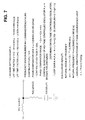
- a filter referred to as a lag-lead filter, of quadratic delay including fixed resistors R1, R2 and a fixed capacitor C is generally employed, as shown in FIG. 7.
- This filter circuit is of simple structure enabling a miniaturized LPF, and further a natural angular frequency ⁇ n and a dumping factor ⁇ can be set independently. These are the reasons for use of such a filter.
- a range to be regarded as converged is that a phase error falls within the range of ⁇ ⁇ /10 (a local oscillator frequency error falls within approximately ⁇ 1 kHz).
- the time consumed until the phase error (or frequency error) falls within the range regarded as converged is considered as a convergence time.
- a time approximating 4 ms is necessary from the beginning of the switchover from the 800M band to the 1.5G band until the local oscillator frequency comes to a proper frequency corresponding to the reception channel or the transmission channel.
- the transition time becomes approximately 2 ms, as a result of calculation similar to the above.
- FIG. 9 there is another way to synthesize a local oscillator signal by use of a fractional divider to achieve a high-speed switchover, as shown in FIG. 9.
- the configuration shown in FIG. 9 is the same as the configuration shown in FIG. 6, except for integer dividers 305 and 405 shown in FIG. 6 are respectively replaced by fractional dividers 315 and 415 in FIG. 9, and further the comparison frequencies are replaced to 400 kHz and 600 kHz.
- This deterioration of the signal spectral purity in the local oscillator frequency produces another problem in the mobile communication terminal: a problem of difficulty in conforming to the standards of adjacent channel leakage power in the transmission characteristics of the mobile communication terminal, and also, to the standard of adjacent channel selectivity and next adjacent channel selectivity in the reception characteristics, as well as the anti-interference capability represented by intermodulation response rejection.
- the fractional divider and the phase comparator is desirably structured of a single monolithic integrated circuit, so as to achieve a miniaturized and lightweight mobile communication terminal.
- cost for structuring the fractional divider into the integrated circuit is high. Namely, a large circuit scale makes it difficult to produce an integrated circuit including a frequency divider operational at a frequency over 1 GHz, in which an arbitrary fractional frequency division number is settable.
- technique of introducing an addition circuit has been proposed, so as to overcome the above-mentioned problem related to the fraction processing against the fractional frequency division number.
- the circuit scale becomes larger. Manufacturing a monolithic LSI for the PLL also brings about higher cost, which retrogrades against technological trend to manufacture a low-cost mobile communication terminal.
- the present invention has been achieved in consideration of the aforementioned background. It is an object of the present invention is to provide radio equipment having a local oscillator signal generator enabling high-speed switchover between two communication bands, and to provide a method for generating two types of local oscillator signals for the radio equipment.
- radio equipment having a local oscillator signal generator easy for structuring in an integrated circuit for the purpose of miniaturization with reduced weight.
- the radio equipment in radio equipment enabling radio communication by performing frequency conversion corresponding to signals of different frequency bands, includes a local oscillator signal generator which further includes: a first signal generator generating a first signal having a first frequency; a second signal generator having a second frequency divider to which a feedback signal is input, a second phase comparator comparing the output signal phase of the second frequency divider with the phase of a second reference input signal having a predetermined frequency, a second filter filtering an output signal of the second phase comparator, and a second voltage controlled oscillator which generates a second signal having a second frequency lower than the first frequency based on the output signal of the second filter, and feedbacks the second signal to the second frequency divider as the feedback signal; and a frequency synthesizer synthesizing the first signal with the second signal, generating a local oscillator signal either having a frequency derived from adding the second frequency to the first frequency, or having a frequency derived from subtracting the second frequency from the first frequency.
- the local oscillator signal generator which further
- the local oscillator signal generation method includes: generating a first signal having a first frequency; generating a second signal having a second frequency lower than the first frequency, by use of a phase lock loop which includes a voltage controlled oscillator, a frequency divider to which a feedback signal is input from the voltage controlled oscillator, a phase comparator comparing a phase of output signal of the frequency divider with a phase of a reference input signal having a predetermined frequency, and a filter filtering output signal of the phase comparator and feeding the output signal to the voltage controlled oscillator; and synthesizing the first signal with the second signal, and generating the local oscillator signal either having a frequency derived from adding the second frequency to the first frequency, or having a frequency derived from subtracting the second frequency from the first frequency.
- the first signal having the first frequency is generated in the first signal generator, and the second signal having the second frequency smaller than the first frequency is generated in the second signal generator.
- These first and second signals are synthesized, and the local oscillator signal either having the frequency derived from adding the second frequency to the first frequency, or having the frequency derived from subtracting the second frequency from the first frequency is generated.
- the local oscillator signal having the frequency derived from adding the second frequency to the first frequency; and the local oscillator signal having the frequency derived from subtracting the second frequency from the first frequency.
- the local oscillator signal is generated for use in converting each frequency of the two bands in radio equipment (exemplarily, dual-band mobile communication terminal), which performs communication by switching frequencies in the two communication bands, to another frequency (exemplarily, intermediate frequency).
- the frequency of the second signal smaller than the frequency of the local oscillator signal generated by the addition can be obtained.
- the first frequency of the first signal generated by the first signal generator is a constant frequency
- the second frequency divider in the second signal generator can set a variable frequency division number
- the second frequency of the second signal generated by the second signal generator is variable corresponding to the frequency division number.
- the second frequency divider is an integer divider having a positive integer value of a frequency division number.
- the frequency synthesizer includes: a first phase shifter shifting the phase of the first signal, and generating a third signal having a phase relatively advanced by ⁇ /2 and a fourth signal having a phase relatively delayed by ⁇ /2; a second phase shifter shifting the phase of the second signal, and generating a fifth signal having a phase relatively advanced by ⁇ /2 and a sixth signal having a phase relatively delayed by ⁇ /2; an inverter/non-inverter inverting the positive or negative sign of the fifth s.ignal when generating the local oscillator signal having a frequency derived from adding the second frequency to the first frequency, or not inverting the positive or negative sign of the fifth signal when generating the local oscillator signal having a frequency derived from subtracting the second frequency from the first frequency; a first multiplier multiplying the third signal by the fifth signal passed through the inverter/non-inverter; a second multiplier multiplying the fourth signal by the sixth signal; and an adder adding
- the radio equipment in radio equipment enabling radio communication by performing frequency conversion corresponding to signals of different frequency bands, includes a local oscillator signal generator which further includes : a first signal generator having a first frequency divider to which a feedback signal is input, a first phase comparator comparing a phase of output signal of the first frequency divider with a phase of a first reference input signal having a predetermined frequency, a first filter filtering output signal of the first phase comparator, and a first voltage controlled oscillator which generates a first signal having a first frequency based on output signal of the first filter, and feedbacks the first signal to the first frequency divider as the feedback signal; a second signal generator having a second frequency divider to which a feedback signal is input, a second phase comparator comparing a phase of output signal of the second frequency divider with the phase of a second reference input signal having a predetermined frequency, a second filter filtering output signal of the second phase comparator, and a second voltage controlled oscillator which generates
- the local oscillator signal generation method includes: generating a first signal having a first frequency by use of a phase lock loop which includes a first voltage controlled oscillator, a first frequency divider to which a feedback signal is input from the first voltage controlled oscillator, a first phase comparator comparing a phase of output signal of the first frequency divider with a phase of a first reference input signal having a predetermined frequency, and a filter filtering output signal of the first phase comparator and feeding the output signal to the first voltage controlled oscillator; generating a second signal having a second frequency different from the first frequency, by use of a phase lock loop which includes a second voltage controlled oscillator, a second frequency divider to which a feedback signal is input from the second voltage controlled oscillator, a second phase comparator comparing a phase
- the local oscillator signal is generated for use in converting each frequency of the two bands in radio equipment (exemplarily, dual-band mobile communication terminal), which performs communication by switching frequencies in the two communication bands, to another frequency (exemplarily, intermediate frequency).
- radio equipment exemplarily, dual-band mobile communication terminal
- the frequency of the first signal smaller than the frequency of the local oscillator signal generated by the addition can be obtained.
- the above description is also applicable to the second signal.
- the radio equipment in a radio equipment generating a signal of a first frequency band by frequency-converting using a signal of a third frequency band, and generating a signal of a second frequency band by frequency-converting using a signal of a fourth frequency band, thereby enabling transmitting whichever signals of the first frequency band and the second frequency band to other radio equipment, the radio equipment includes: a first output section outputting a signal of a predetermined frequency belonging to a band lying between the third frequency band and the fourth frequency band; a secowd output section outputting a signal of a predetermined frequency; and a generation and output section generating and outputting, using the signals from the first output section and the second output section, a signal having a frequency equal to the frequency sum of the signals from the first and second output sections, or a signal having a frequency equal to the frequency difference between the signals from the first and the second output section, respectively as the signal of the third frequency band and the signal of the fourth frequency band.
- the radio equipment in a radio equipment converting a signal frequency of a first frequency band using a signal of a third frequency band, and converting a signal frequency of a second frequency band using a signal of a fourth frequency band, thereby enabling reception of whichever signals of the first frequency band and the second frequency band transmitted fromother radio equipment, the radio equipment includes: a first output section outputting a signal of a predetermined frequency belonging to a band lying between the third frequency band and the fourth frequency band; a second output section outputting a signal of a predetermined frequency; and a generation and output section generating and outputting, using the signals from the first output section and the second output section, a signal having a frequency equal to the frequency sum of the signals from the first and second output sections, or a signal having a frequency equal to the frequency difference between the signals from the first and the second output section, respectively as the signal of the third frequency band and the signal of the fourth frequency band.
- the following embodiment describes a dual-band mobile communication terminal capable of communication on both the 800M band and the 1.5G band in the exemplary mobile communication environment in Japan.
- FIG. 1 shows an explanation diagram of the frequency bands for use in the 800M band and the 1.5G band in Japan.
- bands from 810 MHz to 885 MHz are used as the downlink communication bands from the base station to the mobile communication terminal (i.e. the mobile communication terminal reception bands). Also, bands from 893 MHz to 958 MHz are used for the uplink communication bands from the mobile communication terminal to the base station (i.e. the mobile communication terminal transmission bands).
- Both the downlink communication bands and the uplink communication bands are divided into bands commonly known as A-band (former analog band), C-band and D-band (digital bands), which are kmown to those having general knowledge (and skilled in the art) in the field of the invention. Therefore, the detailed description is omitted here.
- bands from 1,477 MHz to 1,501 MHz are used as the downlink communication bands, and bands from 1,429 MHz to 1,453 MHz are used as the uplink communication bands.
- a reception channel is set up using one frequency band (among the frequency bands allocated at 25 kHz intervals) of the downlink communication bands, while a transmission channel is set up using one frequency (among the frequency bands allocated at 25 kHz intervals) of the uplink communication bands.
- local oscillator frequencies of the local oscillator signals (local signals for transmission) for use in converting the IF (intermediate frequency) transmission signals to the RF (radio frequency) transmission signals are allocated in the bands from 633 MHz to 698 MHz, while local oscillator frequencies of the local oscillator signals (local signals for reception) for use in converting the RF (radio frequency) transmission signals to the IF (intermediate frequency) transmission signals are allocated in the bands from 680 MHz to 755 MHz.
- local oscillator frequencies of the local oscillator signals coincide with local oscillator frequencies of the local oscillator signals (local signals for reception), which are allocated in the bands from 1,347 MHz to 1,371 MHz.
- FIG. 2 shows a block diagram of a configuration of the dual-band mobile communication terminal according to the embodiment of the present invention.
- This dual-band mobile communication terminal (hereafter simply referred to as terminal) is capable of communicating, for example, on both the 800M band and the 1.5G band.
- the terminal is provided with antenna 1, antenna switch 2, transmitter/receiver 3 for the 800M band, transmitter/receiver 4 for the 1.5G band, intermediate frequency section 5, baseband processor/controller 6 and user input/output section 7.
- Transmitter/receiver 3 for the 800M band includes amplifiers 31 and 32, multipliers (mixers) 33 and 34, integer divider 35, phase comparator 36, low pass filter (hereafter referred to as LPF ) 37, and voltage controlled oscillator (hereafter referred to as VCO) 38.
- transmitter/receiver 4 for the 1.5G band includes amplifiers 41 and 42, multipliers (mixers ) 43 and 44, integer divider 45, phase comparator 46, LPF 47, and VCO 48. Further, transmitter/receivers 3 and 4 is commonly provided with a frequency synthesizer 30 and a demultiplexer (DMUX) 40.
- DMUX demultiplexer
- VCOs 38, 48 preferably includes a single integrated circuit 10, to enable miniaturization and weight reduction of the terminal.
- Intermediate frequency section 5 is,provided with selectors (hereafter referred to as SEL) 51 and 56, a multiplier (mixer) 52, an oscillator 53 for generating a 129.55 MHz local oscillator signal, a demultiplexer (DMUX) 54, a quadrature modulator 55, an oscillator 57 for generating a 260-MHz local oscillator signal, and an oscillator 58 for generating an 82-MHz local oscillator signal.
- selectors hereafter referred to as SEL
- DMUX demultiplexer
- DMUX demultiplexer
- quadrature modulator 55 an oscillator 57 for generating a 260-MHz local oscillator signal
- an oscillator 58 for generating an 82-MHz local oscillator signal.
- Antenna 1 transmits and receives radio signals on the 800M band and the 1.5G band, which includes, for example, a whip antenna and a diversity antenna.
- Antenna switch 2 feeds a radio signal of the 800M band to transmitter/receiver 3, or a radio signal of the 1.5G band to transmitter/receiver 4, respectively being input from antenna 1, and also selects a signal input from transmitter/receiver 3 or 4 and transmits the signal via antenna 1.
- Such a switchover of antenna switch 2 is performed under the control of baseband processor/controller 6.
- Transmitter/receiver 3 converts a reception signal of radio frequency (hereafter referred to as RF reception signal) on the 800M band being input from antenna switch 2 to a reception signal of intermediate frequency (130 MHz fixed, hereafter referred to as IF reception signal), and feed this IF reception signal to intermediate frequency section 5. Also, transmitter/receiver 3 converts a transmission signal of intermediate frequency (260 MHz constant, hereafter referred to as IF transmission signal) fed from intermediate frequency section 5 to a transmission signal of radio frequency (hereafter referred to as RF transmission signal) on the 800M band, and feeds this RF transmission signal to antenna switch 2.
- RF reception signal radio frequency
- transmitter/receiver 4 converts a 1.5G-band RF reception signal to an IF reception signal (130 MHz, fixed), and an IF transmission signal (82 MHz, constant) to a 1.5G-band RF transmission signal, and feeds this RF transmission signal to antenna switch 2.
- the IF reception signal and the IF transmission signal have constant frequencies.
- the RF reception signal and the RF transmission signal have frequencies that vary depending on the channel being set up in the bands in FIG. 1 illustrated before.
- one of the 800M-band IF reception signal and the 1. 5G band IF reception signal is selected by SEL 51, and fed to multiplier 52.
- a signal having a local oscillator frequency of 129.55 MHz is fed by oscillator 53.
- the IF reception signal is converted into a signal having a frequency of 450 kHz (constant).
- the converted signal is then fed to baseband processor/controller 6.
- Selection control in SEL 51 is performed by baseband processor/controller 6. (The control line is not shown in the figure.)
- the transmission signal is input from baseband processor/controller 6 in the form of an in-phase signal (I signal) and a quadrature signal (Q signal). These transmission signals are fed to quadrature modulator 55 in intermediate frequency section 5.
- I signal in-phase signal
- Q signal quadrature signal
- the local oscillator signal (or local signal) of 260 MHz (constant) fed from oscillator 57, or the local oscillator signal of 82 MHz (constant) fed from oscillator 58 is input.
- SEL 56 selects the local oscillator signal fed from oscillator 57 when quadrature modulator 55 processes the 800M-band transmission signal, or selects the local oscillator signal fed from oscillator 58 when quadrature modulator 55 processes the 1.5G-band transmission signal.
- Such selection by SEL 56 is performed under the control of baseband processor/controller 6 (the control line not shown in the figure.)
- Quadrature modulator 55 performs quadrature modulation of the I signal and the Q signal input from baseband processor/controller 6, and converts the quadrature modulation signal into the IF transmission signal having a frequency of 260 MHz or 82 MHz by use of the local oscillator signal input from SEL 56.
- This IF transmission signal is fed to DMUX 54.
- the 800M-band IF transmission signal is then fed to multiplier 34, while the 1.5G-band IF transmission signal is fed to multiplier 44.
- Such output path selection by DMUX 54 is performed under the control of baseband processor/controller 6 (the control line not shown in the figure).
- Baseband processor/controller 6 processes the signal input from intermediate frequency section 5, and outputs the processed signal to user input/output section 7. At the same time, baseband processor/controller 6 processes the signal (voice signal, video signal, or the like) being input from a user via user input/output section 7, and feeds the processed signal to intermediate frequency section 5. Further, baseband processor/controller 6 controls SELs 51, 56, DMUXs 54, 40, as described earlier, as well as frequency synthesizer 30 (described in detail later), etc.
- User input/output section 7 is provided with speaker, microphone, display unit (liquid crystal display, or the like), camera, etc.
- User input/output section 7 outputs the signal fed from baseband processor/controller 6 to the speaker, the display unit, etc., and feeds the signal input from the microphone, the camera, etc. to baseband processor/controller 6.
- a signal loop which originates from integer divider 35, passes through phase comparator 36, LPF 37, and VCO 38, and returns to integer divider 35, forms a phase lock loop (hereafter referred to as PLL).
- PLL phase lock loop
- integer divider 35 a fixed value of the frequency division number N1 (integer value) is set.
- This frequency division number N1 may be stored in advance in integer divider 35, or may be set by baseband processor/controller 6 at the time of initiating the terminal.
- phase comparator 36 an output signal from integer divider 35 and a signal having a constant frequency F I fed from a non-illustrated oscillator (for example, crystal oscillator) are input.
- the signal from the oscillator may be fed from the oscillator via a non-illustrated frequency divider.
- VCO 38 a signal having a constant frequency F U (hereafter referred to as a first frequency) is fed to both frequency synthesizer 30 and integer divider 35.
- a signal loop which originates from integer divider 45, passes through phase comparator 46, LPF 47, and VCO 48, and returns to integer divider 45, forms a PLL.
- variable frequency division number N2 integer value
- a variable frequency division number N2 corresponding to each frequency of either the RF reception signal or the RF transmission signal on the 800M band is set, or, a variable frequency division number N2 corresponding to each frequency of the RF reception signal or the RF transmission signal on the 1.5G band is set.
- the control lines for setting are not shown in the figure.
- phase comparator 46 both an output signal from integer divider 45 and a signal having a constant frequency F II fed from a non-illustrated oscillator (for example, crystal oscillator) are input. Or this signal fed from the oscillator may be fed from the oscillator via a non-illustrated frequency divider. With this, a signal having a frequency F L (hereafter referred to as a second frequency) corresponding to each frequency (which is variable at frequency intervals F II ) of the RF reception signal or the RF transmission signal is fed from VCO 48 to both frequency synthesizer 30 and integer divider 45.
- a non-illustrated oscillator for example, crystal oscillator
- the frequencies of the RF reception signal and the RF transmission signal vary (at intervals of 25 kHz), depending on the channel assigned at the time of communication, in the bandwidths shown in FIG. 1.
- representative frequency values are used in the following description.
- a frequency of 689 MHz is used as representative value of the local oscillator frequency on the 800M band.
- This representative frequency value corresponds to the local oscillator frequency for the transmission frequency of 949 MHz and the reception frequency of 819 MHz.
- a frequency of 1,359 MHz is used as representative value of the local oscillator frequency on the 1.5G band.
- This representative frequency value corresponds to the local oscillator frequency for the transmission frequency of 1,441 MHz and the reception frequency of 1,489 MHz.
- this value shows merely an example, and it is not necessary to use the exact median. Any other frequency between the two local oscillator frequencies may be used.
- the combination of the frequency division number N1 and the frequency F I also is an example. It may also be possible to use any other combination with which VCO 38 can generate the first frequency F U .
- the second frequency F L is set to a value (variable) capable of generating a frequency of the 800M-band local oscillator signal (representative value of 689 MHz) and a frequency of the 1.5G-band local oscillator signal (representative value of 1,359 MHz), by synthesizing with the first frequency F U in frequency synthesizer 30.
- frequency synthesizer 30 As an example of frequency synthesis performed in frequency synthesizer 30, addition or subtraction of the frequencies can be used. Namely, frequency synthesizer 30 generates a signal having the 1.5G-band local oscillator frequency of 1,359 MHz (representative value), which is derived from adding a signal having the second frequency F L to a signal having the first frequency F U . Also, frequency synthesizer 30 generates a signal having the 800M-band local oscillator frequency of 689 MHz (representative value), which is derived from subtracting a signal having the second frequency F L from the signal having the first frequency F U .
- 335 [MHz] (representative value)
- This second frequency F L is a relatively low frequency located in the lower limit of the UHF band.
- the signal fed to phase comparator 46 having a constant frequency F II is set to 25 KHz, so that the local oscillator frequency signals (reference input signals) at 25 kHz intervals are synthesized.
- FIG. 3 shows relations among the first frequency F U , the second frequency F L , and the local oscillator frequencies synthesized by the first frequency F U and the second frequency F L .
- the second frequency F L is set between 269 MHz and 391 MHz.
- the variation of the frequency division number N2 on the 1.5G band ranges from 12,920 to 13,880, because the local oscillator frequency range of the 1.5G band is narrower than that of the 800M band.
- the above-mentioned frequency division number of such integer divider 45 becomes on the order of one fourth of the conventional frequency division number.
- the convergence time of the second frequency F II becomes approximately one fourth of the conventional convergence time of approximately 4 ms, that is, on the order of 1 ms (1/1000 sec).
- This second frequency F L is used for generating both the local oscillator frequency of the 800M band and the local oscillator frequency of the 1.5G band. Accordingly, the convergence time of both the 800M-band local oscillator frequency and the 1.5G-band local oscillator frequency become on the order of one fourth of 4 ms, i.e. approximately 1 ms. In contrast, it is not necessary to consider the convergence time of the first frequency F U , because the first frequency F U is fixed (namely, in a convergence state at any time).
- the switchover time from the 800M band to the 1.5G band, and also from the 1.5G band to the 800M band can be shortened, resulting in the switchover time of approximately 1 ms or less in both cases.
- the requirement for the terminal to switch over in real time can be satisfied.
- the terminal can be configured of a miniaturized and light structure having low power consumption.
- integer divider 35 it becomes possible to prevent the spectral purity of the local oscillator frequency signals from deterioration. Also it becomes easier to conform to the standards of adjacent channel leakage power in the transmission characteristics, and also in the reception characteristics, adjacent channel selectivity and next adjacent channel selectivity, as well as the anti-interference capability represented by intermodulation response rejection.
- Frequency synthesizer 30 generates frequencies (representative value of 689 MHz) of the 800M-band local oscillator signal by subtracting the second frequency F L from the first frequency F U .
- Frequency synthesizer 30 also generates frequencies (representative value of 1,359 MHz) of the 1.5G-band local oscillator signal by adding the second frequency F L to the first frequency F U .
- these local oscillator frequencies are generated by indirectly synthesizing from the two frequencies through the arithmetic operations of the signals.
- 'indirectly' signifies that the local oscillator frequency sources are not used as direct frequency sources.
- a frequency sum or a frequency difference of two frequencies can be derived from multiplying the two frequencies in a multiplier.
- By multiplying the two frequencies in the multiplier carrier signal of the two frequency sources is suppressed, and the energy thereof is equally divided to a lower sideband produced from the frequency difference, and to an upper sideband produced from the frequency sum.
- By the use of a filter an unused frequency on one side is attenuated, and only the other frequency for use is obtained through the filter.
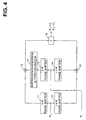
- FIG. 4 shows a block diagram illustrating a detailed configuration of frequency synthesizer 30 according to the embodiment of the present invention.
- Frequency synthesizer 30 is provided with - ⁇ /4 phase shifters 11 and 15, + ⁇ /4 phase shifters 12 and 16, multipliers 13 and 14, an inversion/non-inversion alteration switch 17, and an adder 18.
- the local oscillator signal S1 having the first frequency F U output from VCO 38 (refer to FIG. 2) is input to - ⁇ /4 phase shifter 11 and + ⁇ /4 phase shifter 12. Also, the local oscillator signal S2 having the second frequency F L output from VCO 48 (refer to FIG. 2) is input to - ⁇ /4 phase shifter 15 and + ⁇ /4 phase shifter 16.
- inversion/non-inversion alteration switch 17 To obtain the frequency difference, the sign of the signal output from the - ⁇ /4 phase shifter 15 is not inverted (that is, the input signal is output without alteration) based on a control signal fed from baseband processor/controller 6 (control signal line not shown in the figure). On the other hand, to obtain the frequency sum, the sign of the signal is inverted (that is, the voltage value of the input signal is inverted and output.)
- multiplier 14 multiplies the signal S12 output from the phase shifter 12 by the signal S15 output from the phase shifter 15, and outputs a product A2.
- Adder 18 adds the product A1 and the product A2, and outputs a sum R.
- the signal S15 output from phase shifter 15 is inverted.
- Such frequency synthesizer 30 can be actualized as an integrated circuit of small scale.
- Frequency synthesizer 30 can be formed in the integrated circuit having several millimeters square by employing, for example, a chip size package (CSP).
- CSP chip size package
- ASIC application specific integrated circuit
- phase shifters typically, though four ⁇ /4 phase shifters are included in one frequency synthesizer 30, it is easy to actualize these phase shifters in an integrated circuit. The reason is that by using a process for monolithic microwave integrated circuit, the phases can be varied arbitrarily by providing a transmission line having an appropriate length. Or, by forming coils and capacitors of distributed constant, it is possible to use a phase shifter with the combinations of such coils and capacitors. It may also be possible to form a coil of lumped constant in a spiral shape, or to form a capacitor of lumped constant by forming an area of appropriate size. It is also possible to use a delay line.
- multipliers 13 and 14 a circuit named Gilbert Cell can be used.
- the basic Gilbert Cell circuit has a few numbers of transistors and accompanies approximately 10 fixed resistors. Therefore, by incorporating in a monolithic integrated circuit, transistors having uniform relative characteristics can be used in this Gilbert Cell circuit. Accordingly, this Gilbert Cell circuit can function as virtually ideal multiplier, as is well known to those skilled in the art. As described above, because the circuit scale is small, frequency synthesizer 30 can be formed in an integrated circuit.
- the inversion/non-inversion alteration switch can easily be obtained by separating a signal into two branches, with one branching signal passing through, while the other being amplified by an inversion amplifier having a gain of 1, and by selecting, with a switch, either one of the paths by control logic. Or, it is easily possible to obtain by inserting a delay line having a phase shift amount of ⁇ , or a transmission line corresponding to the phase shift amount of ⁇ , in one of the paths.
- frequency synthesizer 30 enables provision of a miniaturized terminal, with reduced cost and power consumption as well.
- phase shifter 11 and + ⁇ /4 phase shifter 12 are provided against the branching signal having the first frequency F U .
- each phase shift amount in phase shifters 11, 12 is not limited to the value described above. other phase shift amount may be applicable as far as the two branching signals of the first frequency F U are mutually phase-shifted by ⁇ /2 (90 degrees). The above description is also applicable to each phase shift amount of phase shifters 15 and 16.
- a terminal capable of handling the 800M band and the 1.5G band has been disclosed.
- the present invention can be applied to a terminal capable of handling the 800 MHz band and the 1.9 GHz band in North America, or a terminal capable of handling the 900 MHz band and the 1.8 GHz band in Europe.
- the first frequency is set fixed, and the second frequency is set variable.
- the first signal having the first frequency may be obtained by, for example, a crystal oscillator (or, crystal oscillator and a frequency divider), in place of the PLL.
- the present invention relates to a local oscillator signal generator and a method for generating a local oscillator signal, and in particular, a local oscillator signal generator and a method for generating a local oscillator signal, thereby generating local oscillator signals including two different frequencies.
- a local oscillator signal generator and a method for generating a local oscillator signal can be used for a dual-band mobile communication terminal capable of dealing with two bands.
- convergence time of a local oscillator signal can be shortened, and accordingly, when the present invention is applied to a dual-band mobile communication terminal, it becomes possible to communicate using two bands switched in real time.
Landscapes
- Engineering & Computer Science (AREA)
- Computer Networks & Wireless Communication (AREA)
- Signal Processing (AREA)
- Computer Hardware Design (AREA)
- Microelectronics & Electronic Packaging (AREA)
- Transceivers (AREA)
- Transmitters (AREA)
Abstract
Radio equipment enabling radio communication with
frequency conversion corresponding to signals of different
frequency bands is disclosed. A local oscillator signal
generator included in this radio equipment having a first
signal generator, a second signal generator, and a
frequency synthesizer generating a local oscillator signal.
A first signal having first frequency is generated in the
first signal generator, and a second signal having second
frequency smaller than the first frequency is generated
in the second signal generator. These first and second
signals are synthesized, and the local oscillator signal
either having the frequency derived from adding the second
frequency to the first frequency, or having the frequency
derived from subtracting the second frequency from the
first frequency is generated.
Description
The present invention relates to radio equipment, and
more particularly radio equipment having a local oscillator
signal generator, generating local oscillator signals
including two types of frequencies, so as to perform
communication by switching frequencies of two
communication bands in real time. Also, the present
invention relates to a method for generating local
oscillator signals having two types of frequencies in radio
equipment.
In recent years, mobile communication becomes widely
used, and the number of users who use mobile communication
terminals such as portable telephone, automobile telephone,
Personal Digital Assistant (PDA) is increasing.
For such mobile communication in Japan, a multiplicity
of radio bands are in use: UHF 800 MHz band, or shortly,
800M band; quasi-microwave band of 1.5 GHz band, or shortly,
1.5G band; and 1.9 GHz band for use in the PHS (Personal
Handy-phone System). Among them, especially in regard to
the 800M band for use in portable telephone services, there
is an anxiety of line capacity shortage to come, because
the number of users are increasing, and the lines are also
used for data communication, et cetera.
Therefore, in order to solve the problem of line
capacity shortage, there is a demand for a mobile
communication terminal enabling continuation of
communication by switching even during talking on a phone
to another band having room in line capacity at the moment.
For example, the demand for the mobile communication
terminal is such that the terminal can deal with both the
800M band and the 1.5G band, and that when an applicable
channel in the 800M band becomes short during communication,
the connection is automatically hopped to use a channel
of the 1.5G band, or vice versa. Such a mobile communication
terminal is referred to as dual-band mobile communication
terminal.
That is, the dual-band mobile communication terminal
detects, while using one band, an idle slot in another band
in real time, to stimulate the base station to shift to
the detected idle slot. Thus a shift to the idle slot is
performed, which is referred to as MAHO i.e. the mobile
assisted hand-over. In addition, the dual-band mobile
communication terminal shifts the slot from one band to
another in real time based on the instruction of the base
station, irrespective of the terminal in waiting of a call
or a packet, or already in a communication state.
Such a demand to the dual-band mobile communication
terminal also appears in a mobile communication terminal
outside the country, because of, for example, commencement
of data communication through GPRS (GSM packet radio
service) in overseas countries, in which anxiety of
frequency shortage to come also has to be taken into
consideration.
Further, in IMT-2000, a wideband CDMA service is to
be performed using the 2 GHz band, in which a harmonized
service with the existent UHF band service is necessary
until the service areas for the wideband CDMA are
sufficiently expanded. The dual-band mobile communication
terminal is also required from this viewpoint.
In order to actualize such a dual-band mobile
communication terminal, it is necessary for the mobile
communication terminal to provide two sets of
transmitter/receivers that process respective bands. FIG.
6 shows a block diagram illustrating the configuration of
a dual-band mobile communication terminal corresponding
to 800 MHz band and 1.5 GHz band, which is structured using
conventional technique.
To process the two bands i.e. the 800M bands and the
1.5G band, the dual-band mobile communication terminal
shown in FIG. 6 is provided with a transmitter/receiver
103, which processes 800M band signals, and a
transmitter/receiver 104, which processes 1.5G band
signals.
In case that a radio frequency signal (RF reception
signal) received by an antenna 101 is an 800M band signal,
this RF reception signal is fed to an amplifier 301 provided
in transmitter/receiver 103 via an antenna switch 102, and
the signal is amplified therein. After the signal
amplification, a multiplier (mixer) 303 multiplies the RF
reception signal by a local oscillator signal fed from a
voltage-controlled oscillator (VCO) 308 to convert the RF
reception signal into an intermediate frequency (130 MHz)
signal (IF reception signal). Thereafter, the signal is
fed to an intermediate frequency section 105.
On the other hand, in case that an RF reception signal
is a 1.5G band signal, this RF reception signal is fed to
an amplifier 401 of transmitter/receiver 104 via antenna
switch 102, and amplified therein. After the signal is
amplified, a multiplier (mixer) 403 multiplies the RF
reception signal by a local oscillator signal fed from a
voltage controlled oscillator (VCO) 408, to convert the
RF reception signal to an IF reception signal having the
intermediate frequency (130 MHz), and thereafter, the
signal is fed to intermediate frequency section 105.
In intermediate frequency section 105, one of the IF
reception signal fed from either transmitter/receiver 103
or transmitter/receiver 104 is selected. After the selected
IF reception signal is further frequency-converted, the
signal is fed to a baseband processor/controller 106.
Meanwhile, a transmission signal fed to intermediate
frequency section 105 from baseband processor/controller
106 is converted to either a signal (IF transmission signal)
of 260 MHz in case the transmission signal is to be
transmitted through an 800M band channel, or an IF
transmission signal of 82 MHz in case the transmission
signal is to be transmitted through a 1.5G band channel.
Thereafter, the signal is fed to either multiplier (mixer)
304 in transmitter/receiver 103 or multiplier (mixer) 404
in transmitter/receiver 104.
In multiplier 304, the IF transmission signal is
multiplied by the local oscillator signal fed from VCO 308,
and frequency converted into an 800M-band RF transmission
signal. In multiplier 404, the IF transmission signal is
multiplied by the local oscillator signal fed from VCO 408,
and frequency converted into a 1.5G-band RF transmission
signal. Each RF transmission signal is amplified by an
amplifier 302 or 402, and thereafter transmitted from
antenna 101 via antenna switch 102.
Here, switchover control of antenna switch 102 is
performed by baseband processor/controller 106.
However, in such a dual-band mobile communication
terminal, it is not possible to switch over promptly between
the channels of the two bands. In the dual-band mobile
communication terminal, channel switchover is required in
real time, typically within an allowed limit of
approximately 1 millisecond (ms) for the switchover. In
contrast, according to the configuration shown in FIG. 6,
the switchover time from the 800M band to the 1.5G band
is on the order of 4 ms. The reason for this is shown below.
In both the 800M band and the 1 . 5G band, the RF reception
signal and the RF transmission signal have variable
frequencies, which vary within a predetermined range ( 810
MHz - 885 MHz in case of the 800M-band RF reception signal,
as shown later in FIG. 1) in accordance with the channel
allocated at the time of communication.
In order to frequency-convert the RF reception signal
of variable frequency into a constant IF reception signal
of 130 MHz, or to frequency-convert a constant IF
transmission signal of either 260 MHz or 82 MHz to the RF
transmission signal of variable frequency, the frequency
of the local oscillator signal output from VCO 308 or 408
is controlled to vary in accordance with the RF reception
signal frequency or the RF transmission signal frequency.
Now, because it becomes complicated to describe these
frequencies using a variable range, a representative value
is defined for explanation purpose. Based on this
representative value, the switchover time requiring 4 ms
is explained in the following.
A representative value of an RF transmission frequency
of the 800M band is set to 949 MHz (the center value of
the transmission frequency, i.e. the uplink frequency),
and a representative value of a reception frequency is set
to 819 MHz (the center value of the reception frequency,
i.e. the downlink frequency). Further, a representative
value of a local oscillator frequency is set to 689 MHz
(which is the local oscillator frequency in case of the
transmission frequency of 949 MHz and the reception
frequency of 819 MHz). Also, a representative value of an
RF transmission frequency of the 1.5G band is set to 1,441
MHz (the center value of the uplink frequency), and a
representative value of a reception frequency is set to
1,489 MHz (the center value of the downlink frequency).
Further, a representative value of a local oscillator
frequency is set to 1,359 MHz (which is the local oscillator
frequency in case of the transmission frequency of 1,441
MHz and the reception frequency of 1,489 MHz).
The local oscillator signal of the 800M band is
generated by a phase lock loop (PLL) structured of a signal
loop originating from an integer divider 305, passing
through a phase comparator 306, a low pass filter (LPF)
307, and VCO 308, and returning to integer divider 305.
Similarly, the local oscillator signal of the 1.5G band
is generated by a PLL structured of a signal loop originating
from an integer divider 405, passing through a phase
comparator 406, an LPF 407, and VCO 408, and returning to
integer divider 405.
A comparison frequency input to phase comparators 306
and 406 is set to no greater than 25 kHz, so as to synthesize
the local oscillator frequencies at 25 kHz intervals, which
are channel intervals in both the 800M band and the 1.5G
band. Here, the comparison frequency is set to 25 kHz, as
shown in FIG. 6.
In this case, at the local oscillator frequency of
1,359 MHz of the 1.5G band, the frequency division number
N of integer divider 405 becomes: N = 1,359 MHz/25 kHz =
54,360.
The loop gain of the PLL is inversely proportional
to the frequency division number N. Therefore, the PLL loop
gain becomes smaller in the 1.5G band. This is the reason
of the channel switchover time becoming approximately 4
ms.
More specifically, as LPF 307 and LPF 407 in the mobile
communication terminal, a filter, referred to as a lag-lead
filter, of quadratic delay including fixed resistors R1,
R2 and a fixed capacitor C is generally employed, as shown
in FIG. 7. This filter circuit is of simple structure
enabling a miniaturized LPF, and further a natural angular
frequency ωn and a dumping factor ξ can be set independently.
These are the reasons for use of such a filter.
According to the LPF shown in FIG. 7, as shown in the
calculation result in FIG. 7, natural angular frequency
becomes: ωn = 2.266K [rad/s] (360.8 Hz), and the PLL
converges with vibrating with a natural vibration period
T=1/Fn =1/360.8 = 2.772 ms. Here, Fn is a natural frequency,
and is represented by Fn = ωn/2π.
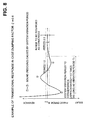
The transitional response thereof is that the
vibration almost converges in approximately three times
of the bound (rebound), as shown in FIG. 8, on assumption
of the dumping factor ξ = 0.6 (where, 0. 5 - 0.7 is considered
appropriate). Here, a range to be regarded as converged
is that a phase error falls within the range of ± π/10
(a local oscillator frequency error falls within
approximately ± 1 kHz). The time consumed until the phase
error (or frequency error) falls within the range regarded
as converged is considered as a convergence time.
Accordingly, when the switchover is performed from
the 800M band to the 1.5G band, the time consumed from the
response to the convergence is approximately 1.5 times as
long as the vibration period T = 2.772 ms, that is,
approximately 4 ms. In other words, a time approximating
4 ms is necessary from the beginning of the switchover from
the 800M band to the 1.5G band until the local oscillator
frequency comes to a proper frequency corresponding to the
reception channel or the transmission channel. Meanwhile,
with regard to the switchover from the 1.5G band to the
800M band, the transition time becomes approximately 2 ms,
as a result of calculation similar to the above.
In contrast, there is another way to synthesize a local
oscillator signal by use of a fractional divider to achieve
a high-speed switchover, as shown in FIG. 9. The
configuration shown in FIG. 9 is the same as the
configuration shown in FIG. 6, except for integer dividers
305 and 405 shown in FIG. 6 are respectively replaced by
fractional dividers 315 and 415 in FIG. 9, and further the
comparison frequencies are replaced to 400 kHz and 600 kHz.
Fractional dividers 315, 415 can take a fractional
number as the frequency division number (for example, the
frequency division number = 54,383/24 = 2,265 + 23/24 =
2,265.9583 (circulating decimal)), while the integer
divider has an integer frequency division number only.
An advantage of the fractional divider lies in that
the intervals of the frequency division number less than
an integer value (for example, at intervals of 0.1) is
settable. With this, the comparison frequency higher than
25 kHz is settable. This enables a larger PLL loop gain
K, and as a result, the convergence time can be shortened.
For example, assuming the local oscillator frequency is
1,359.575 MHz, and the frequency division number is
54,383/24 = 2,265+23/24 = 2,265.95833 ... (circular decimal),
the comparison frequency becomes 1,359.575 MHz/{2,265 +
(23/24)} = 600 kHz.
This figure corresponds to 24 times as much as the
comparison frequency shown in FIG. 6, (24 = 600kHz/25kHz),
and the PLL loop gain K multiplied by this multiple number
can be obtained. Accordingly, the frequency convergence
time becomes approximately 1/24 of that shown in FIG. 6,
and as a result, the frequency convergence time = 4 ms* (1/24)
≒ 166.7 microsecond (µs ) can be obtained. Thus, it becomes
possible to satisfy the requirement for the dual-band
mobile communication terminal.
However, when using such a fractional divider, an
irregular jitter caused by the fraction adjustment of the
frequency division number is produced in the divided signal
waveform. This is equivalent to superposed noise, producing
noise superposed in the synthesized local oscillator
frequency. As a result, there arises a problem of
deteriorated spectral purity produced in the local
oscillator signal, as shown in FIG. 10.
This deterioration of the signal spectral purity in
the local oscillator frequency produces another problem
in the mobile communication terminal: a problem of
difficulty in conforming to the standards of adjacent
channel leakage power in the transmission characteristics
of the mobile communication terminal, and also, to the
standard of adjacent channel selectivity and next adjacent
channel selectivity in the reception characteristics, as
well as the anti-interference capability represented by
intermodulation response rejection.
Further, the fractional divider and the phase
comparator is desirably structured of a single monolithic
integrated circuit, so as to achieve a miniaturized and
lightweight mobile communication terminal. However, cost
for structuring the fractional divider into the integrated
circuit is high. Namely, a large circuit scale makes it
difficult to produce an integrated circuit including a
frequency divider operational at a frequency over 1 GHz,
in which an arbitrary fractional frequency division number
is settable. Additionally, technique of introducing an
addition circuit has been proposed, so as to overcome the
above-mentioned problem related to the fraction processing
against the fractional frequency division number. However,
because of this addition circuit, the circuit scale becomes
larger. Manufacturing a monolithic LSI for the PLL also
brings about higher cost, which retrogrades against
technological trend to manufacture a low-cost mobile
communication terminal.
The present invention has been achieved in
consideration of the aforementioned background. It is an
object of the present invention is to provide radio
equipment having a local oscillator signal generator
enabling high-speed switchover between two communication
bands, and to provide a method for generating two types
of local oscillator signals for the radio equipment.
Further, it is another object of the invention to
provide radio equipment having a local oscillator signal
generator enabling no deterioration of frequency spectral
purity, and a local oscillator signal generation method
for the radio equipment.
Also, it is still another object of the present
invention to provide radio equipment having a local
oscillator signal generator easy for structuring in an
integrated circuit for the purpose of miniaturization with
reduced weight.
According to a first aspect of the present invention,
in radio equipment enabling radio communication by
performing frequency conversion corresponding to signals
of different frequency bands, the radio equipment includes
a local oscillator signal generator which further includes:
a first signal generator generating a first signal having
a first frequency; a second signal generator having a second
frequency divider to which a feedback signal is input, a
second phase comparator comparing the output signal phase
of the second frequency divider with the phase of a second
reference input signal having a predetermined frequency,
a second filter filtering an output signal of the second
phase comparator, and a second voltage controlled
oscillator which generates a second signal having a second
frequency lower than the first frequency based on the output
signal of the second filter, and feedbacks the second signal
to the second frequency divider as the feedback signal;
and a frequency synthesizer synthesizing the first signal
with the second signal, generating a local oscillator
signal either having a frequency derived from adding the
second frequency to the first frequency, or having a
frequency derived from subtracting the second frequency
from the first frequency. The radio equipment uses the local
oscillator signal generated by the frequency synthesizer
for frequency conversion in the radio communication.
According to the first aspect of the present invention,
in a local oscillator signal generation method for
generating a local oscillator signal for use in frequency
conversion in radio equipment enabling radio communication
by performing frequency conversion corresponding to
signals on different frequency bands, the local oscillator
signal generation method includes: generating a first
signal having a first frequency; generating a second signal
having a second frequency lower than the first frequency,
by use of a phase lock loop which includes a voltage
controlled oscillator, a frequency divider to which a
feedback signal is input from the voltage controlled
oscillator, a phase comparator comparing a phase of output
signal of the frequency divider with a phase of a reference
input signal having a predetermined frequency, and a filter
filtering output signal of the phase comparator and feeding
the output signal to the voltage controlled oscillator;
and synthesizing the first signal with the second signal,
and generating the local oscillator signal either having
a frequency derived from adding the second frequency to
the first frequency, or having a frequency derived from
subtracting the second frequency from the first frequency.
According to the first aspect of the invention, the
first signal having the first frequency is generated in
the first signal generator, and the second signal having
the second frequency smaller than the first frequency is
generated in the second signal generator. These first and
second signals are synthesized, and the local oscillator
signal either having the frequency derived from adding the
second frequency to the first frequency, or having the
frequency derived from subtracting the second frequency
from the first frequency is generated.
According to the first aspect of the invention, it
is possible to generate two type of local oscillator
signals: the local oscillator signal having the frequency
derived from adding the second frequency to the first
frequency; and the local oscillator signal having the
frequency derived from subtracting the second frequency
from the first frequency. With this, the local oscillator
signal is generated for use in converting each frequency
of the two bands in radio equipment (exemplarily, dual-band
mobile communication terminal), which performs
communication by switching frequencies in the two
communication bands, to another frequency (exemplarily,
intermediate frequency).
Also, the frequency of the second signal smaller than
the frequency of the local oscillator signal generated by
the addition can be obtained. With this, it becomes possible
to set the frequency division number of the second frequency
divider smaller than the frequency division number being
set when the local oscillator signal is directly generated
by the second signal generator. As a result, it becomes
possible to obtain a smaller convergence time of the second
signal generator than the convergence time in the
conventional method. Accordingly, when this local
oscillator signal generator is employed in a dual-band
mobile communication terminal, a high-speed switchover
between the two communication bands can be obtained.
Preferably, the first frequency of the first signal
generated by the first signal generator is a constant
frequency, the second frequency divider in the second
signal generator can set a variable frequency division
number, and the second frequency of the second signal
generated by the second signal generator is variable
corresponding to the frequency division number. with this,
the control becomes easy even in case of varying the
frequency of the local oscillator signal.
Further, preferably, the second frequency divider is
an integer divider having a positive integer value of a
frequency division number. With this., it becomes easy to
integrate a unit including the second frequency divider,
and miniaturization of the unit can be actualized. Also,
degradation of the spectral purity that occurs when using
a fractional divider can be prevented.
According to one embodiment of the first aspect of
the present invention, the frequency synthesizer includes:
a first phase shifter shifting the phase of the first signal,
and generating a third signal having a phase relatively
advanced by π/2 and a fourth signal having a phase relatively
delayed by π/2; a second phase shifter shifting the phase
of the second signal, and generating a fifth signal having
a phase relatively advanced by π/2 and a sixth signal having
a phase relatively delayed by π/2; an inverter/non-inverter
inverting the positive or negative sign of the fifth s.ignal
when generating the local oscillator signal having a
frequency derived from adding the second frequency to the
first frequency, or not inverting the positive or negative
sign of the fifth signal when generating the local
oscillator signal having a frequency derived from
subtracting the second frequency from the first frequency;
a first multiplier multiplying the third signal by the fifth
signal passed through the inverter/non-inverter; a second
multiplier multiplying the fourth signal by the sixth
signal; and an adder adding output signal of the first
multiplier and output signal of the second multiplier. With
this, a miniaturized and low-cost frequency synthesizer
with low power consumption can be attained.
According to a second aspect of the present invention,
in radio equipment enabling radio communication by
performing frequency conversion corresponding to signals
of different frequency bands, the radio equipment includes
a local oscillator signal generator which further includes :
a first signal generator having a first frequency divider
to which a feedback signal is input, a first phase comparator
comparing a phase of output signal of the first frequency
divider with a phase of a first reference input signal having
a predetermined frequency, a first filter filtering output
signal of the first phase comparator, and a first voltage
controlled oscillator which generates a first signal having
a first frequency based on output signal of the first filter,
and feedbacks the first signal to the first frequency
divider as the feedback signal; a second signal generator
having a second frequency divider to which a feedback signal
is input, a second phase comparator comparing a phase of
output signal of the second frequency divider with the phase
of a second reference input signal having a predetermined
frequency, a second filter filtering output signal of the
second phase comparator, and a second voltage controlled
oscillator which generates a second signal having a second
frequency different from the first frequency based on
output signal of the second filter, and feedbacks the second
signal to the second frequency divider as the feedback
signal; and a frequency synthesizer synthesizing the first
signal with the second signal, and generating a local
oscillator signal either having a frequency derived from
adding the first frequency to the second frequency, or
having a frequency derived from subtracting the smaller
frequency between the first frequency and the second
frequency, from the larger frequency therebetween. The
radio equipment uses the local oscillator signal generated
by the frequency synthesizer for frequency conversion in
the radio communication.
In a local oscillator signal generation method,
according to the second aspect of the present invention,
for generating a local oscillator signal for use in
frequency conversion in radio equipment enabling radio
communication by performing frequency conversion
corresponding to signals of different frequency bands, the
local oscillator signal generation method includes:
generating a first signal having a first frequency by use
of a phase lock loop which includes a first voltage
controlled oscillator, a first frequency divider to which
a feedback signal is input from the first voltage controlled
oscillator, a first phase comparator comparing a phase of
output signal of the first frequency divider with a phase
of a first reference input signal having a predetermined
frequency, and a filter filtering output signal of the first
phase comparator and feeding the output signal to the first
voltage controlled oscillator; generating a second signal
having a second frequency different from the first
frequency, by use of a phase lock loop which includes a
second voltage controlled oscillator, a second frequency
divider to which a feedback signal is input from the second
voltage controlled oscillator, a second phase comparator
comparing a phase of output signal of the second frequency
divider with a phase of a second reference input signal
having a predetermined frequency, and a filter filtering
output signal of the second phase comparator and feeding
the output signal to the second voltage controlled
oscillator; and synthesizing the first signal with the
second signal, and generating the local oscillator signal
either having a frequency derived from adding the second
frequency to the first frequency, or having a frequency
derived from subtracting the smaller frequency between the
first frequency and the second frequency, from the larger
frequency therebetween.
According to the second aspect of the invention, it
is possible to generate two type of local oscillator
signals: a local oscillator signal having the frequency
derived from adding the second frequency to the first
frequency; and a local oscillator signal having the
frequency derived from subtracting the smaller frequency
between the first frequency and the second frequency, from
the larger frequency therebetween. With this, the local
oscillator signal is generated for use in converting each
frequency of the two bands in radio equipment (exemplarily,
dual-band mobile communication terminal), which performs
communication by switching frequencies in the two
communication bands, to another frequency (exemplarily,
intermediate frequency).
Also, the frequency of the first signal smaller than
the frequency of the local oscillator signal generated by
the addition can be obtained. With this, it becomes possible
to set each frequency division number of the first frequency
divider smaller than the frequency division number being
set when the local oscillator signal is directly generated
by the first signal generator. As a result, it becomes
possible to obtain a shorter convergence time of the first
signal generator than the convergence time in the
conventional method. Accordingly, when this local
oscillator signal generator is employed in a dual-band
mobile communication terminal, a high-speed switchover
between the two communication bands can be obtained. The
above description is also applicable to the second signal.
According to a third aspect of the present invention,
in a radio equipment generating a signal of a first frequency
band by frequency-converting using a signal of a third
frequency band, and generating a signal of a second
frequency band by frequency-converting using a signal of
a fourth frequency band, thereby enabling transmitting
whichever signals of the first frequency band and the second
frequency band to other radio equipment, the radio
equipment includes: a first output section outputting a
signal of a predetermined frequency belonging to a band
lying between the third frequency band and the fourth
frequency band; a secowd output section outputting a signal
of a predetermined frequency; and a generation and output
section generating and outputting, using the signals from
the first output section and the second output section,
a signal having a frequency equal to the frequency sum of
the signals from the first and second output sections, or
a signal having a frequency equal to the frequency
difference between the signals from the first and the second
output section, respectively as the signal of the third
frequency band and the signal of the fourth frequency band.
According to a fourth aspect of the present invention,
in a radio equipment converting a signal frequency of a
first frequency band using a signal of a third frequency
band, and converting a signal frequency of a second
frequency band using a signal of a fourth frequency band,
thereby enabling reception of whichever signals of the
first frequency band and the second frequency band
transmitted fromother radio equipment, the radio equipment
includes: a first output section outputting a signal of
a predetermined frequency belonging to a band lying between
the third frequency band and the fourth frequency band;
a second output section outputting a signal of a
predetermined frequency; and a generation and output
section generating and outputting, using the signals from
the first output section and the second output section,
a signal having a frequency equal to the frequency sum of
the signals from the first and second output sections, or
a signal having a frequency equal to the frequency
difference between the signals from the first and the second
output section, respectively as the signal of the third
frequency band and the signal of the fourth frequency band.
The preferred embodiment of the present invention is
described hereinafter referring to the charts and drawings.
It is noted that the following description shows merely
an example of the embodiments, and the scope of the invention
is not limited to the embodiments described below.
The following embodiment describes a dual-band mobile
communication terminal capable of communication on both
the 800M band and the 1.5G band in the exemplary mobile
communication environment in Japan.
Before starting concrete explanation of the dual-band
mobile communication terminal, the communication bands of
the 800M band and the 1.5G band used in Japan will be
explained briefly, for the sake of easy understanding of
this dual-band mobile communication terminal.
FIG. 1 shows an explanation diagram of the frequency
bands for use in the 800M band and the 1.5G band in Japan.
In the 800M band, bands from 810 MHz to 885 MHz are
used as the downlink communication bands from the base
station to the mobile communication terminal (i.e. the
mobile communication terminal reception bands). Also,
bands from 893 MHz to 958 MHz are used for the uplink
communication bands from the mobile communication terminal
to the base station (i.e. the mobile communication terminal
transmission bands). Both the downlink communication bands
and the uplink communication bands are divided into bands
commonly known as A-band (former analog band), C-band and
D-band (digital bands), which are kmown to those having
general knowledge (and skilled in the art) in the field
of the invention. Therefore, the detailed description is
omitted here.
In the 1.5G band, bands from 1,477 MHz to 1,501 MHz
are used as the downlink communication bands, and bands
from 1,429 MHz to 1,453 MHz are used as the uplink
communication bands.
At the time of communication, a reception channel is
set up using one frequency band (among the frequency bands
allocated at 25 kHz intervals) of the downlink
communication bands, while a transmission channel is set
up using one frequency (among the frequency bands allocated
at 25 kHz intervals) of the uplink communication bands.
Further, in the 800M band, local oscillator
frequencies of the local oscillator signals (local signals
for transmission) for use in converting the IF
(intermediate frequency) transmission signals to the RF
(radio frequency) transmission signals are allocated in
the bands from 633 MHz to 698 MHz, while local oscillator
frequencies of the local oscillator signals (local signals
for reception) for use in converting the RF (radio
frequency) transmission signals to the IF (intermediate
frequency) transmission signals are allocated in the bands
from 680 MHz to 755 MHz. Meanwhile, in the 1.5G band, local
oscillator frequencies of the local oscillator signals
(local signals for transmission) coincide with local
oscillator frequencies of the local oscillator signals
(local signals for reception), which are allocated in the
bands from 1,347 MHz to 1,371 MHz.
Now, hereafter, the configuration of the dual-band
mobile communication terminal according to the embodiment
of the present invention is described in the following.
FIG. 2 shows a block diagram of a configuration of the
dual-band mobile communication terminal according to the
embodiment of the present invention. This dual-band mobile
communication terminal (hereafter simply referred to as
terminal) is capable of communicating, for example, on both
the 800M band and the 1.5G band.
The terminal is provided with antenna 1, antenna switch
2, transmitter/receiver 3 for the 800M band,
transmitter/receiver 4 for the 1.5G band, intermediate
frequency section 5, baseband processor/controller 6 and
user input/output section 7.
Transmitter/receiver 3 for the 800M band includes
amplifiers 31 and 32, multipliers (mixers) 33 and 34,
integer divider 35, phase comparator 36, low pass filter
(hereafter referred to as LPF ) 37, and voltage controlled
oscillator (hereafter referred to as VCO) 38. Also,
transmitter/receiver 4 for the 1.5G band includes
amplifiers 41 and 42, multipliers (mixers ) 43 and 44,
integer divider 45, phase comparator 46, LPF 47, and VCO
48. Further, transmitter/receivers 3 and 4 is commonly
provided with a frequency synthesizer 30 and a
demultiplexer (DMUX) 40.
Here, VCOs 38, 48 preferably includes a single
integrated circuit 10, to enable miniaturization and weight
reduction of the terminal.
Transmitter/receiver 3 converts a reception signal
of radio frequency (hereafter referred to as RF reception
signal) on the 800M band being input from antenna switch
2 to a reception signal of intermediate frequency (130 MHz
fixed, hereafter referred to as IF reception signal), and
feed this IF reception signal to intermediate frequency
section 5. Also, transmitter/receiver 3 converts a
transmission signal of intermediate frequency (260 MHz
constant, hereafter referred to as IF transmission signal)
fed from intermediate frequency section 5 to a transmission
signal of radio frequency (hereafter referred to as RF
transmission signal) on the 800M band, and feeds this RF
transmission signal to antenna switch 2.
Similarly, transmitter/receiver 4 converts a
1.5G-band RF reception signal to an IF reception signal
(130 MHz, fixed), and an IF transmission signal (82 MHz,
constant) to a 1.5G-band RF transmission signal, and feeds
this RF transmission signal to antenna switch 2.
The IF reception signal and the IF transmission signal
have constant frequencies. In contrast, the RF reception
signal and the RF transmission signal have frequencies that
vary depending on the channel being set up in the bands
in FIG. 1 illustrated before.
In intermediate frequency section 5, one of the
800M-band IF reception signal and the 1. 5G band IF reception
signal is selected by SEL 51, and fed to multiplier 52.
To multiplier 52, a signal having a local oscillator
frequency of 129.55 MHz is fed by oscillator 53. With this,
the IF reception signal is converted into a signal having
a frequency of 450 kHz (constant). The converted signal
is then fed to baseband processor/controller 6. Selection
control in SEL 51 is performed by baseband
processor/controller 6. (The control line is not shown in
the figure.)
Meanwhile, to intermediate frequency section 5, the
transmission signal is input from baseband
processor/controller 6 in the form of an in-phase signal
(I signal) and a quadrature signal (Q signal). These
transmission signals are fed to quadrature modulator 55
in intermediate frequency section 5.
From SEL 56 to quadrature modulator 55, the local
oscillator signal (or local signal) of 260 MHz (constant)
fed from oscillator 57, or the local oscillator signal of
82 MHz (constant) fed from oscillator 58 is input. SEL 56
selects the local oscillator signal fed from oscillator
57 when quadrature modulator 55 processes the 800M-band
transmission signal, or selects the local oscillator signal
fed from oscillator 58 when quadrature modulator 55
processes the 1.5G-band transmission signal. Such
selection by SEL 56 is performed under the control of
baseband processor/controller 6 (the control line not shown
in the figure.)
Baseband processor/controller 6 processes the signal
input from intermediate frequency section 5, and outputs
the processed signal to user input/output section 7. At
the same time, baseband processor/controller 6 processes
the signal (voice signal, video signal, or the like) being
input from a user via user input/output section 7, and feeds
the processed signal to intermediate frequency section 5.
Further, baseband processor/controller 6 controls SELs 51,
56, DMUXs 54, 40, as described earlier, as well as frequency
synthesizer 30 (described in detail later), etc.
User input/output section 7 is provided with speaker,
microphone, display unit (liquid crystal display, or the
like), camera, etc. User input/output section 7 outputs
the signal fed from baseband processor/controller 6 to the
speaker, the display unit, etc., and feeds the signal input
from the microphone, the camera, etc. to baseband
processor/controller 6.
In transmitter/receiver 3, a signal loop, which
originates from integer divider 35, passes through phase
comparator 36, LPF 37, and VCO 38, and returns to integer
divider 35, forms a phase lock loop (hereafter referred
to as PLL).
In integer divider 35, a fixed value of the frequency
division number N1 (integer value) is set. This frequency
division number N1 may be stored in advance in integer
divider 35, or may be set by baseband processor/controller
6 at the time of initiating the terminal.
To phase comparator 36, an output signal from integer
divider 35 and a signal having a constant frequency FI fed
from a non-illustrated oscillator (for example, crystal
oscillator) are input. The signal from the oscillator may
be fed from the oscillator via a non-illustrated frequency
divider. With this, from VCO 38, a signal having a constant
frequency FU (hereafter referred to as a first frequency)
is fed to both frequency synthesizer 30 and integer divider
35.
Similarly in transmitter/receiver 4, a signal loop,
which originates from integer divider 45, passes through
phase comparator 46, LPF 47, and VCO 48, and returns to
integer divider 45, forms a PLL.
In integer divider 45, a variable frequency division
number N2 (integer value), corresponding to each frequency
of either the RF reception signal or the RF transmission
signal on the 800M band is set, or, a variable frequency
division number N2 corresponding to each frequency of the
RF reception signal or the RF transmission signal on the
1.5G band is set. (The control lines for setting are not
shown in the figure.)
To phase comparator 46, both an output signal from
integer divider 45 and a signal having a constant frequency
FII fed from a non-illustrated oscillator (for example,
crystal oscillator) are input. Or this signal fed from the
oscillator may be fed from the oscillator via a
non-illustrated frequency divider. With this, a signal
having a frequency FL (hereafter referred to as a second
frequency) corresponding to each frequency (which is
variable at frequency intervals FII) of the RF reception
signal or the RF transmission signal is fed from VCO 48
to both frequency synthesizer 30 and integer divider 45.
Here, the frequencies of the RF reception signal and
the RF transmission signal vary (at intervals of 25 kHz),
depending on the channel assigned at the time of
communication, in the bandwidths shown in FIG. 1. For the
sake of easy understanding, in place of these frequencies,
representative frequency values are used in the following
description.
Similar to the foregoing description on the background
art, a frequency of 689 MHz is used as representative value
of the local oscillator frequency on the 800M band. This
representative frequency value corresponds to the local
oscillator frequency for the transmission frequency of 949
MHz and the reception frequency of 819 MHz. Also, as
representative value of the local oscillator frequency on
the 1.5G band, a frequency of 1,359 MHz is used. This
representative frequency value corresponds to the local
oscillator frequency for the transmission frequency of
1,441 MHz and the reception frequency of 1,489 MHz.
The difference between these local oscillator
frequencies equals to 670 MHz (=1,359MHz-689MHz). Namely,
the two frequencies have sufficient spaces between each
other. Therefore, even under variable conditions, these
local oscillator frequencies do not overlap nor approach.
Accordingly, the median of these frequencies is obtained,
and defined as a first frequency FU to be fed from VCO 38
to the frequency synthesizer.
The first frequency
FU = (689 + 1,359)/2 = 1,024 [MHz]
(constant value)
Here, this value shows merely an example, and it is
not necessary to use the exact median. Any other frequency
between the two local oscillator frequencies may be used.
In order to set FU = 1,024 MHz, for example, the frequency
division number N1 = 1,024, and FI = 1,000 kHz are set.
The combination of the frequency division number N1 and
the frequency FI also is an example. It may also be possible
to use any other combination with which VCO 38 can generate
the first frequency FU.
Meanwhile, the second frequency FL is set to a value
(variable) capable of generating a frequency of the
800M-band local oscillator signal (representative value
of 689 MHz) and a frequency of the 1.5G-band local oscillator
signal (representative value of 1,359 MHz), by synthesizing
with the first frequency FU in frequency synthesizer 30.
As an example of frequency synthesis performed in
frequency synthesizer 30, addition or subtraction of the
frequencies can be used. Namely, frequency synthesizer 30
generates a signal having the 1.5G-band local oscillator
frequency of 1,359 MHz (representative value), which is
derived from adding a signal having the second frequency
FL to a signal having the first frequency FU. Also, frequency
synthesizer 30 generates a signal having the 800M-band
local oscillator frequency of 689 MHz (representative
value), which is derived from subtracting a signal having
the second frequency FL from the signal having the first
frequency FU.
In such a case, the second frequency FL (representative
value) is set as follows:
FL = 1024 - 689 = |1024 - 1359| = 335 [MHz]
(representative value)
This second frequency FL is a relatively low frequency
located in the lower limit of the UHF band.
Because the transmission/reception channel are
allocated at 25 KHz intervals, the signal fed to phase
comparator 46 having a constant frequency FII is set to
25 KHz, so that the local oscillator frequency signals
(reference input signals) at 25 kHz intervals are
synthesized. Meanwhile, the frequency division number N2
of integer divider 45 is set to N2 = 13,400 (representative
value), so that the second frequency FL = 335 MHz
(representative value) can be generated. By incrementing
or decrementing this frequency division number N2, local
oscillator frequencies are generated at 25 kHz intervals
for adjacent channels.
FIG. 3 shows relations among the first frequency FU,
the second frequency FL, and the local oscillator
frequencies synthesized by the first frequency FU and the
second frequency FL. In cons ideration of the variation width
of the 800M-band local oscillator frequencies and the
variation width of the 1.5G-band local oscillator
frequencies, the second frequency FL is set between 269
MHz and 391 MHz. In other words, the frequency division
number N2 is set variably between 10,760 (= 269 MHz/25 kHz)
and 15,640 (=391 MHz/25 kHz). Additionally, as shown in
FIG. 3, the variation of the frequency division number N2
on the 1.5G band ranges from 12,920 to 13,880, because the
local oscillator frequency range of the 1.5G band is
narrower than that of the 800M band.
The above-mentioned frequency division number of such
integer divider 45 becomes on the order of one fourth of
the conventional frequency division number. As a result,
the convergence time of the second frequency FII becomes
approximately one fourth of the conventional convergence
time of approximately 4 ms, that is, on the order of 1 ms
(1/1000 sec).
This second frequency FL is used for generating both
the local oscillator frequency of the 800M band and the
local oscillator frequency of the 1.5G band. Accordingly,
the convergence time of both the 800M-band local oscillator
frequency and the 1.5G-band local oscillator frequency
become on the order of one fourth of 4 ms, i.e. approximately
1 ms. In contrast, it is not necessary to consider the
convergence time of the first frequency FU, because the
first frequency FU is fixed (namely, in a convergence state
at any time).
As a result, the switchover time from the 800M band
to the 1.5G band, and also from the 1.5G band to the 800M
band, can be shortened, resulting in the switchover time
of approximately 1 ms or less in both cases. Thus, the
requirement for the terminal to switch over in real time
can be satisfied.
Further, according to the embodiment, it becomes
easier to configure the portions shown below, with
monolithic integrated circuits (PLL integrated circuits),
respectively: the portion illustrated using a symbol 21
shown in FIG. 2, which includes integer divider 35, phase
comparator 36, and generator circuit generating frequency
FI, for example, a crystal oscillator (or a crystal
oscillator and an integer divider); and also the portion
illustrated using a symbol 22, which includes integer
divider 45, phase comparator 46, and generator circuit
generating frequency FII, for example, a crystal oscillator
(or a crystal oscillator and an integer divider). As a result,
the terminal can be configured of a miniaturized and light
structure having low power consumption.
Further, by use of integer divider 35, it becomes
possible to prevent the spectral purity of the local
oscillator frequency signals from deterioration. Also it
becomes easier to conform to the standards of adjacent
channel leakage power in the transmission characteristics,
and also in the reception characteristics, adjacent channel
selectivity and next adjacent channel selectivity, as well
as the anti-interference capability represented by
intermodulation response rejection.
Next, a detailed configuration of frequency
synthesizer 30 will be described hereafter. Frequency
synthesizer 30 generates frequencies (representative
value of 689 MHz) of the 800M-band local oscillator signal
by subtracting the second frequency FL from the first
frequency FU. Frequency synthesizer 30 also generates
frequencies (representative value of 1,359 MHz) of the
1.5G-band local oscillator signal by adding the second
frequency FL to the first frequency FU.
As such, these local oscillator frequencies are
generated by indirectly synthesizing from the two
frequencies through the arithmetic operations of the
signals. Here, 'indirectly' signifies that the local
oscillator frequency sources are not used as direct
frequency sources.
In general, a frequency sum or a frequency difference
of two frequencies can be derived from multiplying the two
frequencies in a multiplier. By multiplying the two
frequencies in the multiplier, carrier signal of the two
frequency sources is suppressed, and the energy thereof
is equally divided to a lower sideband produced from the
frequency difference, and to an upper sideband produced
from the frequency sum. By the use of a filter, an unused
frequency on one side is attenuated, and only the other
frequency for use is obtained through the filter.
However, for this purpose, use of a dielectric of TEM
mode, separate circuit elements such as coils and
capacitors, and a laminated ceramic LC filter retrogrades
against technical trends toward miniaturization and cost
reduction of the terminal. Further, because the energy is
equally divided to both sidebands, as described above,
required energy in one sideband is in principle a half of
the original energy. In other words, the other half of the
original energy is wasted in the other sideband not for
use. The use of the filter unworthily eliminating the unused
energy on the other sideband retrogrades a technical trend
toward lower power consumption.
From this viewpoint, in the embodiment of the present
invention, a frequency synthesis method, different from
the conventional method, is introduced. FIG. 4 shows a block
diagram illustrating a detailed configuration of frequency
synthesizer 30 according to the embodiment of the present
invention.
The local oscillator signal S1 having the first
frequency FU output from VCO 38 (refer to FIG. 2) is input
to -π/4 phase shifter 11 and +π/4 phase shifter 12. Also,
the local oscillator signal S2 having the second frequency
FL output from VCO 48 (refer to FIG. 2) is input to -π/4
phase shifter 15 and +π/4 phase shifter 16.
For easy understanding of calculation, assuming that
the local oscillator signal S1 = cos (ωUt) (where, (ωU = 2πFU),
a signal S11 output from phase shifter 11 becomes
S11 = cos(ωUt - π/4), and a signal S12 output from phase
shifter 12 becomes S12 = cos(ωUt + π/4). Also, assuming
the local oscillator signal S2 = cos(ωLt ) (ωL = 2πFL), then
a signal S15 output from phase shifter 15 becomes S15 =
cos(ωLt - π/4), and a signal S16 output from phase shifter
16 becomes S16 = cos(ωLt + π/4).
With regard to inversion/non-inversion alteration
switch 17, to obtain the frequency difference, the sign
of the signal output from the -π/4 phase shifter 15 is not
inverted (that is, the input signal is output without
alteration) based on a control signal fed from baseband
processor/controller 6 (control signal line not shown in
the figure). On the other hand, to obtain the frequency
sum, the sign of the signal is inverted (that is, the voltage
value of the input signal is inverted and output.)
Because the signal is not inverted when the frequency
difference (FL - FU) is to obtain, in this case, multiplier
13 multiplies the signal S11 output from the phase shifter
11, namely S11 = cos(ωUt - π/4), by the signal S16 output
from the phase shifter 16, namely S15 = cos(ωLt - π/4),
and outputs a product A1.

Meanwhile, multiplier 14 multiplies the signal S12
output from the phase shifter 12 by the signal S15 output
from the phase shifter 15, and outputs a product A2.

Thus, the frequency of this sum R, which is equal to
a difference of the first frequency FU from the second
frequency FL, is obtained.
On the other hand, to obtain the frequency sum (FL +
FU), the signal S15 output from phase shifter 15 is inverted.
Multiplier 13 multiplies the signal S11 output from phase
shifter 11, namely S11 = cos(ωUt - π/4), by the inverted
output signal S15 from phase shifter 15, namely -S15 =
-cos(ωLt - π/4), and outputs a product A3.

Meanwhile, the multiplied result of multiplier 14 is
the same as the above-mentioned multiplied result A2.
Therefore, the sum R output from adder 18 is,
R = A3 + A2 = -sin(ωU + ωL )t = -sin2π(FU + FL )t
Thus, a frequency sum of the first frequency FU and
the second frequency FL is obtained.
Typically, though four π/4 phase shifters are included
in one frequency synthesizer 30, it is easy to actualize
these phase shifters in an integrated circuit. The reason
is that by using a process for monolithic microwave
integrated circuit, the phases can be varied arbitrarily
by providing a transmission line having an appropriate
length. Or, by forming coils and capacitors of distributed
constant, it is possible to use a phase shifter with the
combinations of such coils and capacitors. It may also be
possible to form a coil of lumped constant in a spiral shape,
or to form a capacitor of lumped constant by forming an
area of appropriate size. It is also possible to use a delay
line.
Also, for multipliers 13 and 14 a circuit named Gilbert
Cell can be used. The basic Gilbert Cell circuit has a few
numbers of transistors and accompanies approximately 10
fixed resistors. Therefore, by incorporating in a
monolithic integrated circuit, transistors having uniform
relative characteristics can be used in this Gilbert Cell
circuit. Accordingly, this Gilbert Cell circuit can
function as virtually ideal multiplier, as is well known
to those skilled in the art. As described above, because
the circuit scale is small, frequency synthesizer 30 can
be formed in an integrated circuit.
The inversion/non-inversion alteration switch can
easily be obtained by separating a signal into two branches,
with one branching signal passing through, while the other
being amplified by an inversion amplifier having a gain
of 1, and by selecting, with a switch, either one of the
paths by control logic. Or, it is easily possible to obtain
by inserting a delay line having a phase shift amount of
π, or a transmission line corresponding to the phase shift
amount of π, in one of the paths.
As such, frequency synthesizer 30 enables provision
of a miniaturized terminal, with reduced cost and power
consumption as well.
Additionally, in FIG. 4, -π/4 phase shifter 11 and
+π/4 phase shifter 12 are provided against the branching
signal having the first frequency FU. However, each phase
shift amount in phase shifters 11, 12 is not limited to
the value described above. other phase shift amount may
be applicable as far as the two branching signals of the
first frequency FU are mutually phase-shifted by π/2 (90
degrees). The above description is also applicable to each
phase shift amount of phase shifters 15 and 16.
Further, as shown in FIG. 5, it is possible to provide
π/2 phase shifters 19 and 20, by which the phase of π/2
is shifted in only one of the branching signals.
Through the description explained above, a terminal
capable of handling the 800M band and the 1.5G band has
been disclosed. However, it may also be possible to apply
the present invention to other terminals for different
bands. For example, the present invention can be applied
to a terminal capable of handling the 800 MHz band and the
1.9 GHz band in North America, or a terminal capable of
handling the 900 MHz band and the 1.8 GHz band in Europe.
In the above describe of the embodiment, the first
frequency is set fixed, and the second frequency is set
variable. However, it may also be possible to set both
frequencies variable, or to set the first frequency
variable with the second frequency fixed.
In addition, when the first frequency is set fixed,
the first signal having the first frequency may be obtained
by, for example, a crystal oscillator (or, crystal
oscillator and a frequency divider), in place of the PLL.
The present invention relates to a local oscillator
signal generator and a method for generating a local
oscillator signal, and in particular, a local oscillator
signal generator and a method for generating a local
oscillator signal, thereby generating local oscillator
signals including two different frequencies. Such a local
oscillator signal generator and a method for generating
a local oscillator signal can be used for a dual-band mobile
communication terminal capable of dealing with two bands.
According to the present invention, convergence time
of a local oscillator signal can be shortened, and
accordingly, when the present invention is applied to a
dual-band mobile communication terminal, it becomes
possible to communicate using two bands switched in real
time.
The foregoing description of the embodiments is not
intended to limit the invention to the particular details
of the examples illustrated. Any suitable modification and
equivalents may be resorted to the scope of the invention.
All features and advantages of the invention which fall
within the scope of the invention are covered by the appended
claims.
Claims (19)
- A radio equipment enabling radio communication by performing frequency conversion corresponding to signals of different frequency bands, and including a local oscillator signal generator comprising:wherein the radio equipment uses the local oscillator signal generated by the frequency synthesizer for frequency conversion in the radio communication.a first signal generator generating a first signal having a first frequency;a second signal generator having a second frequency divider to which a feedback signal is input, a second phase comparator comparing a phase of output signal of the second frequency divider with a phase of a second reference input signal having a predetermined frequency, a second filter filtering output signal of the second phase comparator, and a second voltage controlled oscillator which generates a second signal having a second frequency lower than the first frequency based on output signal of the second filter, and feedbacks. the second signal to the second frequency divider as the feedback signal; anda frequency synthesizer synthesizing the first signal with the second signal, generating a local oscillator signal either having a frequency derived from adding the second frequency to the first frequency, or having a frequency derived from subtracting the second frequency from the first frequency,
- The radio equipment according to claim 1,
wherein the first frequency of the first signal generated by the first signal generator is a constant frequency, the second frequency divider in the second signal generator can set a variable frequency division number, and the second frequency of the second signal generated by the second signal generator is variable corresponding to the frequency division number. - The radio equipment according to either claim 1 or 2,
wherein the second frequency divider is an integer divider having a positive integer value of a frequency division number. - The radio equipment according to any one of claim 1 to 3,
wherein at least the second frequency divider and the second phase comparator among the second signal generator are formed in a single integrated circuit. - The radio equipment according to any one of claim 1 to 4,
wherein the first signal generator comprises:a first frequency divider to which a feedback signal is input;a first phase comparator comparing a phase of output signal of the first frequency divider with a phase of a first reference input signal having a predetermined frequency;a first filter filtering output signal of the first phase comparator; anda first voltage controlled oscillator which generates the first signal having the first frequency based on output signal of the first filter, and feedbacks the first signal to the first frequency divider as the feedback signal. - The radio equipment according to claim 5,
wherein the first voltage controlled oscillator and the second voltage controlled oscillator are formed in a single integrated circuit. - The radio equipment according to either claim 5 or 6,
wherein the first frequency divider is an integer divider having a positive integer value of a frequency division number. - The radio equipment according to any one of claim 5 to 7,
wherein at least the first frequency divider and the first phase comparator among the first signal generator are formed in a single integrated circuit. - The radio equipment according to any one of claim 1 to 8,
wherein the frequency synthesizer comprises:a first phase shifter shifting the phase of the first signal, and generating a third signal having a phase relatively advanced by π/2 and a fourth signal having a phase relatively delayed by π/2;a second phase shifter shifting the phase of the second signal, and generating a fifth signal having a phase relatively advanced by π/2 and a sixth signal having a phase relatively delayed by π/2;an inverter/non-inverter inverting the positive or negative sign of the fifth signal when generating the local oscillator signal having a frequency derived from adding the second frequency to the first frequency, or not inverting the positive or negative sign of the fifth signal when generating the local oscillator signal having a frequency derived from subtracting the second frequency from the first frequency;a first multiplier multiplying the third signal by the fifth signal passed through the inverter/non-inverter;a second multiplier multiplying the fourth signal by the sixth signal; andan adder adding output signal of the first multiplier and output signal of the second multiplier. - The radio equipment according to claim 9,
wherein the first phase shifter comprises a phase shifter generating the third signal by advancing the phase of the first signal by π/4, and a phase shifter generating the fourth signal by delaying the phase of the first signal by π/4. - The radio equipment according to either claim 9 or 10
wherein the second phase shifter comprises a phase shifter generating the fifth signal by advancing the phase of the second signal by π/4, and a phase shifter generating the sixth signal by delaying the phase of the second signal by π/4. - The radio equipment according to claim 9,
wherein the first phase shifter comprises a phase shifter generating the third signal by advancing the phase of the first signal by π/2, and generates the fourth signal without shifting the phase of the first signal. - The radio equipment according to either claim 9 or 12,
wherein the second phase shifter comprises a phase shifter generating the fifth signal by advancing the phase of the second signal by π/2, and generates the sixth signal without shifting the phase of the second signal. - The radio equipment according to any one of claim 1 to 13,
wherein the convergence time of the second signal generated by the second signal generator is no longer than one-thousandth (1/1,000) sec. - Radio equipment enabling radio communication by performing frequency conversion corresponding to signals of different frequency bands, and including a local oscillator signal generator comprising:wherein the radio equipment uses the local oscillator signal generated by the frequency synthesizer for frequency conversion in the radio communication.a first signal generator having a first frequency divider to which a feedback signal is input, a first phase comparator comparing a phase of output signal of the first frequency divider with a phase of a first reference input signal having a predetermined frequency, a first filter filtering output signal of the first phase comparator, and a first voltage controlled oscillator which generates a first signal having a first frequency based on output signal of the first filter, and feedbacks the first signal to the first frequency divider as the feedback signal;a second signal generator having a second frequency divider to which a feedback signal is input, a second phase comparator comparing a phase of output signal phase of the second frequency divider with a phase of a second reference input signal having a predetermined frequency, a second filter filtering output signal of the second phase comparator, and a second voltage controlled oscillator which generates a second signal having a second frequency different from the first frequency based on output signal of the second filter, and feedbacks the second signal to the second frequency divider as the feedback signal; anda frequency synthesizer synthesizing the first signal with the second signal, and generating a local oscillator signal either having a frequency derived from adding the first frequency to the second frequency, or having a frequency derived from subtracting the smaller frequency between the first frequency and the second frequency, from the larger frequency therebetween,
- A local oscillator signal generation method for generating a local oscillator signal for use in frequency conversion in radio equipment enabling radio communication by performing frequency conversion corresponding to signals on different frequency bands, comprising:generating a first signal having a first frequency;generating a second signal having a second frequency lower than the first frequency, by use of a phase lock loop which includes a voltage controlled oscillator, a frequency divider to which a feedback signal is input from the voltage controlled oscillator, a phase comparator comparing a phase of output signal of the frequency divider with a phase of a reference input signal having a predetermined frequency, and a filter filtering output signal of the phase comparator and feeding the output signal to the voltage controlled oscillator; andsynthesizing the first signal with the second signal, and generating the local oscillator signal either having a frequency derived from adding the second frequency to the first frequency, or having a frequency derived from subtracting the second frequency from the first frequency.
- A local oscillator signal generation method for generating a local oscillator signal for use in frequency conversion in radio equipment enabling radio communication by performing frequency conversion corresponding to signals of different frequency bands, comprising:generating a first signal having a first frequency by use of a phase lock loop which includes a first voltage controlled oscillator, a first frequency divider to which a feedback signal is input from the first voltage controlled oscillator, a first phase comparator comparing a phase of output signal of the first frequency divider with the phase of a first reference input signal having a predetermined frequency, and a f ilter filtering output signal of the first phase comparator and feeding the output signal to the first voltage controlled oscillator;generating a second signal having a second frequency different from the first frequency, by use of a phase lock loop which includes a second voltage controlled oscillator, a second frequency divider to which a feedback signal is input from the second voltage controlled oscillator, a second phase comparator comparing a phase of output signal of the second frequency divider with a phase of a second reference input signal having a predetermined frequency, and a filter filtering output signal of the second phase comparator and feeding the output signal to the second voltage controlled oscillator; andsynthesizing the first signal with the second signal, and generating the local oscillator signal either having a frequency derived from adding the second frequency to the first frequency, or having a frequency derived from subtracting the smaller frequency between the first frequency and the second frequency, from the larger frequency therebetween.
- A radio equipment generating a signal of a first frequency band by frequency-converting using a signal of a third frequency band, and generating a signal of a second frequency band by frequency-converting using a signal of a fourth frequency band, thereby enabling transmitting whichever signals of the first frequency band and the second frequency band to other radio equipment, said radio equipment comprising:a first output section outputting a signal of a predetermined frequency belonging to a band lying between the third frequency band and the fourth frequency band;a second output section outputting a signal of a predetermined frequency; anda generation and output section generating and outputting, using the signals from the first output section and the second output section, a signal having a frequency equal to the frequency sum of the signals from the first and second output sections, or a signal having a frequency equal to the frequency difference between the signals from the first and the second output sections, respectively as the signal of the third frequency band and the signal of the fourth frequency band.
- A radio equipment converting a signal frequency of a first frequency band using a signal of a third frequency band, and converting a signal frequency of a second frequency band using a signal of a fourth frequency band, thereby enabling reception of whichever signals of the first frequency band and the second frequency band transmitted from other radio equipment, said radio equipment comprising:a first output section outputting a signal of a predetermined frequency belonging to a band lying between the third frequency band and the fourth frequency band;a second output section outputting a signal of a predetermined frequency; anda generation and output section generating and outputting, using the signals from the first output section and the second output section, a signal having a frequency equal to the frequency sum of the signals from the first and second output sections, or a signal having a frequency equal to the frequency difference between the signals from the first and the second output sections, respectively as the signal of the third frequency band and the signal of the fourth frequency band.
Priority Applications (1)
| Application Number | Priority Date | Filing Date | Title |
|---|---|---|---|
| EP08153850A EP1995873A2 (en) | 2001-10-03 | 2001-10-03 | Radio equipment communicatable in two frequency bands and method for generating local oscillator signal in radio equipment |
Applications Claiming Priority (1)
| Application Number | Priority Date | Filing Date | Title |
|---|---|---|---|
| PCT/JP2001/008729 WO2003032508A1 (en) | 2001-10-03 | 2001-10-03 | Wireless apparatus capable of communicating in two frequency bands, and local oscillation signal generating method in the wireless apparatus |
Related Child Applications (1)
| Application Number | Title | Priority Date | Filing Date |
|---|---|---|---|
| EP08153850A Division EP1995873A2 (en) | 2001-10-03 | 2001-10-03 | Radio equipment communicatable in two frequency bands and method for generating local oscillator signal in radio equipment |
Publications (2)
| Publication Number | Publication Date |
|---|---|
| EP1434358A1 true EP1434358A1 (en) | 2004-06-30 |
| EP1434358A4 EP1434358A4 (en) | 2004-10-27 |
Family
ID=11737804
Family Applications (2)
| Application Number | Title | Priority Date | Filing Date |
|---|---|---|---|
| EP01972682A Withdrawn EP1434358A4 (en) | 2001-10-03 | 2001-10-03 | WIRELESS APPARATUS THAT CAN COMMUNICATE IN TWO FREQUENCY BANDS, AND METHOD FOR GENERATING LOCAL OSCILLATION SIGNAL IN WIRELESS DEVICE |
| EP08153850A Withdrawn EP1995873A2 (en) | 2001-10-03 | 2001-10-03 | Radio equipment communicatable in two frequency bands and method for generating local oscillator signal in radio equipment |
Family Applications After (1)
| Application Number | Title | Priority Date | Filing Date |
|---|---|---|---|
| EP08153850A Withdrawn EP1995873A2 (en) | 2001-10-03 | 2001-10-03 | Radio equipment communicatable in two frequency bands and method for generating local oscillator signal in radio equipment |
Country Status (5)
| Country | Link |
|---|---|
| US (2) | US7130603B2 (en) |
| EP (2) | EP1434358A4 (en) |
| JP (1) | JP3929443B2 (en) |
| CN (1) | CN100456643C (en) |
| WO (1) | WO2003032508A1 (en) |
Cited By (1)
| Publication number | Priority date | Publication date | Assignee | Title |
|---|---|---|---|---|
| WO2005074152A1 (en) * | 2004-01-26 | 2005-08-11 | Koninklijke Philips Electronics, N.V. | Frequency generation for a multi-band ofdm based ultra wide-band radio |
Families Citing this family (14)
| Publication number | Priority date | Publication date | Assignee | Title |
|---|---|---|---|---|
| US8249533B2 (en) * | 2003-12-19 | 2012-08-21 | Vixs Systems, Inc. | Rapidly adjustable local oscillation module and applications thereof |
| EP1726099A1 (en) * | 2004-03-02 | 2006-11-29 | Koninklijke Philips Electronics N.V. | Serialization of multi-band sequence keying for ultra wideband receiver architecture with reduced complexity and power consumption |
| US8811369B2 (en) * | 2006-01-11 | 2014-08-19 | Qualcomm Incorporated | Methods and apparatus for supporting multiple communications modes of operation |
| JP4735312B2 (en) * | 2006-02-14 | 2011-07-27 | パナソニック株式会社 | Receiving device and electronic device using the same |
| US7805122B2 (en) * | 2006-08-29 | 2010-09-28 | Texas Instruments Incorporated | Local oscillator with non-harmonic ratio between oscillator and RF frequencies using digital mixing and weighting functions |
| US7809338B2 (en) * | 2006-08-29 | 2010-10-05 | Texas Instruments Incorporated | Local oscillator with non-harmonic ratio between oscillator and RF frequencies using wideband modulation spectral replicas |
| WO2009101993A1 (en) * | 2008-02-14 | 2009-08-20 | Nec Corporation | Phase shifter and method for controlling same, and radio communication device with array antenna |
| US20160286532A1 (en) * | 2012-01-24 | 2016-09-29 | Odyssey Wireless, Inc. | Systems/methods of preferentially using a first asset, refraining from using a second asset and providing reduced levels of interference to gps and/or satellites |
| JP5595883B2 (en) | 2010-11-29 | 2014-09-24 | 株式会社東芝 | Wireless communication device |
| US8890625B2 (en) | 2013-01-03 | 2014-11-18 | Qualcomm Incorporated | Systems and methods for frequency synthesis to improve coexistence |
| CN105721218A (en) * | 2016-03-04 | 2016-06-29 | 深圳采集云数据科技有限公司 | Medical guiding system embedded firmware upgrade system |
| CN105721001A (en) * | 2016-04-14 | 2016-06-29 | 国鹰河北航空科技有限公司 | Unmanned aerial vehicle target positioning system |
| CN105871409B (en) * | 2016-04-29 | 2018-12-04 | 公安海警学院 | transceiver |
| US10693569B1 (en) * | 2019-03-08 | 2020-06-23 | Rohde & Schwarz Gmbh & Co. Kg | Method of providing a phase reference, method for establishing known phase relationships as well as phase reference system |
Family Cites Families (20)
| Publication number | Priority date | Publication date | Assignee | Title |
|---|---|---|---|---|
| JPS57193106A (en) | 1981-05-23 | 1982-11-27 | Nec Corp | Image cancellation type frequency converter |
| GB2103035B (en) * | 1981-08-04 | 1985-01-23 | Marconi Instruments Ltd | Frequency synthesisers |
| JPH0728178B2 (en) | 1987-03-31 | 1995-03-29 | 日本電気株式会社 | Reception frequency converter |
| JPH02143704A (en) | 1988-11-25 | 1990-06-01 | Fujitsu Ltd | Image cancel type frequency converter |
| US4965531A (en) * | 1989-11-22 | 1990-10-23 | Carleton University | Frequency synthesizers having dividing ratio controlled by sigma-delta modulator |
| CA2107632C (en) * | 1992-10-05 | 1997-06-03 | Nec Corporation | Local oscillator and its frequency switching method |
| US5374902A (en) * | 1993-05-12 | 1994-12-20 | Wiltron Company | Ultra low phase noise microwave synthesizer |
| US5535432A (en) * | 1994-09-14 | 1996-07-09 | Ericsson Ge Mobile Communications Inc. | Dual-mode satellite/cellular phone with a frequency synthesizer |
| JPH08223073A (en) * | 1995-02-14 | 1996-08-30 | Fujitsu Ltd | Dual band wireless communication device |
| FI112133B (en) * | 1996-03-29 | 2003-10-31 | Nokia Corp | Method of forming the frequencies of a direct conversion transmitter / receiver operating in two different frequency ranges and a direct conversion transmitter / receiver of a radio communication system operating in two different frequency ranges and using the foregoing in a mobile telephone |
| FI100286B (en) * | 1996-04-01 | 1997-10-31 | Nokia Mobile Phones Ltd | Transmitter / receiver for transmitting and receiving an RF signal in two frequency ranges |
| GB2321353B (en) * | 1996-12-18 | 2000-09-13 | Plessey Semiconductors Ltd | Image-reject mixer arrangements |
| DE19708772A1 (en) * | 1997-03-04 | 1998-06-25 | Siemens Ag | Signal frequency generation method |
| US6724804B1 (en) * | 1998-07-13 | 2004-04-20 | Kabushiki Kaisha Kobe Seiko Sho | Frequency converter and radio communications system employing the same |
| JP2000124739A (en) * | 1998-10-15 | 2000-04-28 | Kyocera Corp | Frequency synthesizer |
| JP2000223956A (en) | 1999-01-29 | 2000-08-11 | Hitachi Ltd | Image cancel mixer circuit |
| DE19928998B4 (en) * | 1999-06-24 | 2005-07-14 | Siemens Ag | Electronic circuit arrangement for generating a transmission frequency |
| US6466803B1 (en) * | 1999-10-19 | 2002-10-15 | Qualcomm, Incorporated | Multi-mode communications system with efficient oscillator synchronization |
| JP2001186042A (en) * | 1999-12-24 | 2001-07-06 | Toshiba Corp | Multi-band wireless communication device |
| JP3626399B2 (en) * | 2000-08-17 | 2005-03-09 | 株式会社東芝 | Frequency synthesizer and multiband radio using the same |
-
2001
- 2001-10-03 EP EP01972682A patent/EP1434358A4/en not_active Withdrawn
- 2001-10-03 WO PCT/JP2001/008729 patent/WO2003032508A1/en not_active Ceased
- 2001-10-03 EP EP08153850A patent/EP1995873A2/en not_active Withdrawn
- 2001-10-03 JP JP2003535348A patent/JP3929443B2/en not_active Expired - Fee Related
- 2001-10-03 CN CNB01823688XA patent/CN100456643C/en not_active Expired - Fee Related
-
2004
- 2004-03-30 US US10/817,410 patent/US7130603B2/en not_active Expired - Lifetime
-
2006
- 2006-07-25 US US11/492,554 patent/US7502595B2/en not_active Expired - Fee Related
Cited By (1)
| Publication number | Priority date | Publication date | Assignee | Title |
|---|---|---|---|---|
| WO2005074152A1 (en) * | 2004-01-26 | 2005-08-11 | Koninklijke Philips Electronics, N.V. | Frequency generation for a multi-band ofdm based ultra wide-band radio |
Also Published As
| Publication number | Publication date |
|---|---|
| EP1995873A2 (en) | 2008-11-26 |
| CN1559107A (en) | 2004-12-29 |
| US20040192240A1 (en) | 2004-09-30 |
| US7130603B2 (en) | 2006-10-31 |
| JP3929443B2 (en) | 2007-06-13 |
| CN100456643C (en) | 2009-01-28 |
| US20060276142A1 (en) | 2006-12-07 |
| WO2003032508A1 (en) | 2003-04-17 |
| EP1434358A4 (en) | 2004-10-27 |
| US7502595B2 (en) | 2009-03-10 |
| JPWO2003032508A1 (en) | 2005-01-27 |
Similar Documents
| Publication | Publication Date | Title |
|---|---|---|
| US6735426B1 (en) | Multiple-band wireless transceiver with quadrature conversion transmitter and receiver circuits | |
| JP4242559B2 (en) | Simplified reference frequency distribution in mobile phones | |
| US6754508B1 (en) | Multiple-band wireless transceiver with quadrature conversion transmitter and receiver circuits | |
| EP1217756A2 (en) | Multiband portable radio terminal | |
| US7130603B2 (en) | Radio equipment communicatable in two frequency bands and method for generating local oscillator signal in radio equipment | |
| WO1999004504A1 (en) | Radio communication equipment | |
| JPH09331273A (en) | Method for transmitting and receiving radio signal | |
| JPH1032520A (en) | Transmitter-receiver sending/receiving radio frequency signal for two frequency bands | |
| US20080233892A1 (en) | Method and system for an integrated vco and local oscillator architecture for an integrated fm transmitter and fm receiver | |
| JPH07221667A (en) | Method for generation of signal of different frequencies in digital radiotelephone | |
| US8340215B2 (en) | Radio transceiver architectures and methods | |
| JP3672189B2 (en) | Radio signal receiving apparatus and demodulation processing circuit | |
| RU2348104C2 (en) | Frequency synthesiser for support of voice communication standards and wireless networks standards | |
| JPH1022852A (en) | Radio communication equipment | |
| JP3410661B2 (en) | Multimode wireless device | |
| EP1503509A1 (en) | Mobile communication apparatus | |
| EP1207627B1 (en) | An efficient GS;/DSC/UMTS (UTRA/FDD) RF transceiver architecture | |
| JP2004538709A (en) | Multi-band transceiver with reduced frequency source for digital transmission | |
| JP4583210B2 (en) | Wireless communication device and mobile phone terminal | |
| EP1255356A1 (en) | Dual mode/triple band frequency synthesiser | |
| JP3530504B2 (en) | Wireless transmission / reception device and mobile phone using the same | |
| JPH05259934A (en) | Transceiver | |
| JP2005033234A (en) | transceiver | |
| JP2006180165A (en) | PLL synthesizer and multi-band radio using the same | |
| JPH06164491A (en) | Digital portable telephone set |
Legal Events
| Date | Code | Title | Description |
|---|---|---|---|
| PUAI | Public reference made under article 153(3) epc to a published international application that has entered the european phase |
Free format text: ORIGINAL CODE: 0009012 |
|
| 17P | Request for examination filed |
Effective date: 20040426 |
|
| AK | Designated contracting states |
Kind code of ref document: A1 Designated state(s): AT BE CH CY DE DK ES FI FR GB GR IE IT LI LU MC NL PT SE TR |
|
| A4 | Supplementary search report drawn up and despatched |
Effective date: 20040914 |
|
| 17Q | First examination report despatched |
Effective date: 20071005 |
|
| STAA | Information on the status of an ep patent application or granted ep patent |
Free format text: STATUS: THE APPLICATION IS DEEMED TO BE WITHDRAWN |
|
| 18D | Application deemed to be withdrawn |
Effective date: 20110502 |