EP1434328A2 - Battery charger - Google Patents
Battery charger Download PDFInfo
- Publication number
- EP1434328A2 EP1434328A2 EP03029443A EP03029443A EP1434328A2 EP 1434328 A2 EP1434328 A2 EP 1434328A2 EP 03029443 A EP03029443 A EP 03029443A EP 03029443 A EP03029443 A EP 03029443A EP 1434328 A2 EP1434328 A2 EP 1434328A2
- Authority
- EP
- European Patent Office
- Prior art keywords
- temperature
- power source
- source circuit
- battery
- charging current
- Prior art date
- Legal status (The legal status is an assumption and is not a legal conclusion. Google has not performed a legal analysis and makes no representation as to the accuracy of the status listed.)
- Granted
Links
Images


Classifications
-
- H—ELECTRICITY
- H01—ELECTRIC ELEMENTS
- H01M—PROCESSES OR MEANS, e.g. BATTERIES, FOR THE DIRECT CONVERSION OF CHEMICAL ENERGY INTO ELECTRICAL ENERGY
- H01M10/00—Secondary cells; Manufacture thereof
- H01M10/42—Methods or arrangements for servicing or maintenance of secondary cells or secondary half-cells
- H01M10/48—Accumulators combined with arrangements for measuring, testing or indicating the condition of cells, e.g. the level or density of the electrolyte
- H01M10/486—Accumulators combined with arrangements for measuring, testing or indicating the condition of cells, e.g. the level or density of the electrolyte for measuring temperature
-
- H—ELECTRICITY
- H01—ELECTRIC ELEMENTS
- H01M—PROCESSES OR MEANS, e.g. BATTERIES, FOR THE DIRECT CONVERSION OF CHEMICAL ENERGY INTO ELECTRICAL ENERGY
- H01M10/00—Secondary cells; Manufacture thereof
- H01M10/42—Methods or arrangements for servicing or maintenance of secondary cells or secondary half-cells
- H01M10/46—Accumulators structurally combined with charging apparatus
-
- H—ELECTRICITY
- H02—GENERATION; CONVERSION OR DISTRIBUTION OF ELECTRIC POWER
- H02J—ELECTRIC POWER NETWORKS; CIRCUIT ARRANGEMENTS OR SYSTEMS FOR SUPPLYING OR DISTRIBUTING ELECTRIC POWER; SYSTEMS FOR STORING ELECTRIC ENERGY
- H02J7/00—Circuit arrangements for charging or discharging batteries or for supplying loads from batteries
- H02J7/90—Regulation of charging or discharging current or voltage
- H02J7/971—Regulation of charging or discharging current or voltage the charge cycle being controlled or terminated in response to non-electric parameters
- H02J7/975—Regulation of charging or discharging current or voltage the charge cycle being controlled or terminated in response to non-electric parameters in response to temperature
- H02J7/977—Regulation of charging or discharging current or voltage the charge cycle being controlled or terminated in response to non-electric parameters in response to temperature of the battery
-
- Y—GENERAL TAGGING OF NEW TECHNOLOGICAL DEVELOPMENTS; GENERAL TAGGING OF CROSS-SECTIONAL TECHNOLOGIES SPANNING OVER SEVERAL SECTIONS OF THE IPC; TECHNICAL SUBJECTS COVERED BY FORMER USPC CROSS-REFERENCE ART COLLECTIONS [XRACs] AND DIGESTS
- Y02—TECHNOLOGIES OR APPLICATIONS FOR MITIGATION OR ADAPTATION AGAINST CLIMATE CHANGE
- Y02E—REDUCTION OF GREENHOUSE GAS [GHG] EMISSIONS, RELATED TO ENERGY GENERATION, TRANSMISSION OR DISTRIBUTION
- Y02E60/00—Enabling technologies; Technologies with a potential or indirect contribution to GHG emissions mitigation
- Y02E60/10—Energy storage using batteries
Definitions
- the present invention relates to battery chargers for charging rechargeable batteries.
- Japanese Laid-open Patent Publication No. 2000-23387 describes a battery charger that suppresses the temperature increase of a power source circuit of the battery charger.
- the known battery charger includes a temperature sensor for detecting the temperature of the power source circuit, and a switch electrically connecting and disconnecting the battery with the power source circuit.
- the switch is turned OFF. As a result, the supply of charging current to the battery from the power source circuit is halted, thereby suppressing the temperature increase of the power source circuit.
- one object of the present teachings to provide improved battery chargers suppresses the temperature increase of the power source circuit while allowing the battery to be charged efficiently.
- a battery pack may include one or more rechargeable battery cells (e.g., nickel metal hydride battery cells, nickel cadmium battery cells).
- the battery pack may have a first temperature sensor for detecting the temperature of the battery cells.
- the battery pack may be coupled to appliances (e.g., cordless power tools, cordless electric vacuum cleaner). When the battery pack is discharged, the battery pack may be preferably detached from the appliance and coupled to a battery charger.
- the battery charger may have a power source circuit arranged and constructed to supply charging current to the battery pack.
- the battery charger may include a second temperature sensor for detecting the temperature of the power source circuit.
- the battery charger may also include a controller (e.g., processor, microprocessor or microcomputer) for controlling the power source circuit.
- the controller preferably (i) selects charging current that will be supplied by the power source circuit to the battery cells based at least upon battery temperature from the first temperature sensor and power source circuit temperature from the second temperature sensor, and (ii) supplies the selected charging current to the battery cells. Since the controller selects charging current based at least upon battery temperature and power source circuit temperature, the battery pack can be charged efficiently while the both temperature increases of the power source circuit and the battery cells can be suppressed.
- the controller preferably calculates battery temperature increase rate based upon signals from the first temperature sensor and power source temperature increase rate based upon signals from the second temperature sensor. Then, the controller selects charging current that will be supplied by the power source circuit to the battery cells based further upon the calculated temperature increase rates. Since the charging current is selected based further upon the battery temperature increase rate and the power source circuit temperature increase rate, the battery pack can be charged more efficiently.
- the controller preferably (1) selects a first allowable charging current value based upon the battery temperature and the battery temperature increase rate, (2) selects a second allowable charging current value based upon the power source circuit temperature and the power source circuit temperature increase rate, and (3) selects the smaller of the first and second allowable charging current values as the charging current that will be supplied by the power source circuit to the battery cells.
- the controller may select the first allowable charging current value form a first look up table using the battery temperature and battery temperature increase rate as indices for the first look up table.
- the controller may select the second allowable charging current value form a second look up table using the power source circuit temperature and power source circuit temperature increase rate as indices for the second look up table.
- the battery charger may further include a memory. The first and second look up table may be stored in the memory of the battery charger.
- the controller preferably terminates the supply of charging current to the battery cells based upon a determination that relatively low first allowable charging currents have been repeatedly selected over series of intervals. Since the controller automatically stops the charging, full charging can be performed without overcharging.
- FIG. 1 is a block diagram schematically showing battery charger 10 connected with battery pack 50.
- Battery pack 50 may include a plurality of nickel metal hydride batteries 55 that are serially connected.
- Battery pack 50 may also include temperature sensor TM1 for detecting the temperature of batteries 55.
- Temperature sensor TM1 may include a thermister having an electrical resistance that varies in accordance with variation in temperature.
- Batteries 55 and temperature sensor TM1 are disposed within a housing of battery pack 50. Connecting terminals C 1' ⁇ C4' are disposed on a surface of the housing of battery pack 50.
- the control circuit of battery charger 10 may include the following functional circuits: power source circuit 32, charging-current control portion 34, control portion 36, second temperature detecting portion 38, first temperature detecting portion 40, and memory 39.
- Power source circuit 32 may be connected with an external commercial power source. Power source circuit 32 supplies charging current to batteries 55 of battery pack 50.
- Power source circuit 32 may comprise a rectifying circuit, a transformer, FETs, and diodes.
- Battery charger 10 may also have temperature sensor TM2 for detecting the temperature of power source circuit 32. Temperature sensor TM2 may be preferably attached to a surface of a diode of a secondary side of the transformer of power source circuit 32.
- temperature sensor TM2 may detect the temperature at another part of power source circuit 32 (e.g., (i) the temperature of a primary side FET (ii) the temperature of the transformer (iii) the temperature of a primary side/secondary side heat waster (iv) the temperature of molded resin (e.g., urethane) (v) the ambient temperature within the charger). Temperature sensor TM2 may also include a thermister having an electrical resistance that varies in accordance with variation in temperature.
- second temperature detecting portion 38 detects the temperature of power source circuit 32 on the basis of signals from temperature sensor TM2.
- Temperature sensor TM1 of battery pack 50 is coupled to first temperature detecting portion 40 via connecting terminals C3 - C3' and C4 - C4'.
- First temperature detecting portion 40 detects the temperature of batteries 55 on the basis of signals from temperature sensor TM2.
- Memory 39 may store current control information, such as a map that stores specific values corresponding to appropriate charging currents, which are supplied to batteries 55 in accordance with the rate of battery temperature increase. Memory 39 is coupled to control portion 36.
- Control portion 36 may comprise a microprocessor or microcomputer that includes, e.g., central processing unit (CPU), read only memory (ROM), random access memory (RAM) and input/output port (I/O).
- Control portion 36 preferably calculates temperature-increase rate of power source circuit 32 by differentiating the temperature of power source circuit 32, which was output from second temperature detecting portion 38.
- Control portion 36 also calculates temperature-increase rate of batteries 55 by differentiating the detected temperature of batteries 55, which was output from first temperature detecting portion 40.
- control portion 36 preferably retrieves a first map and thereby read a first allowable charging current value that permits charging while suppressing an increase in battery temperature. Utilizing the power source circuit temperature and the power source circuit temperature-increase rate, control portion 36 further retrieves a second map and thereby read a second allowable charging current value that permits charging while suppressing an increase in temperature of power source circuit 32. Then, control portion 36 selects the smaller of the first and second allowable charging current values, and control portion 36 preferably outputs the selected allowable charging current value, which serves as a current instruction value, to charging-current control portion 34. Charging-current control portion 34 controls power source circuit 32 on the basis of the selected allowable charging current value output from control portion 36, and adjust the charging current supplied to batteries 55.
- a Nickel metal hydride battery has characteristics that a temperature gradient (i.e., temperature rise value) varies greatly with charging current and already charged capacity. Due to this, in the present representative embodiment, in order to complete charging within a shorter period while preventing the temperature of the battery from rising, the values of the charging current are changed while charging is performed.
- the temperature of the power source circuit increases greatly. This increase in temperature can be mitigated by increasing power source circuit capacity, but this increases size and cost of the power source circuit. Further, if the temperature of the power source circuit is high, charging current may need to be reduced in order to avoid damaging the power source circuit.
- both battery temperature and power source circuit temperature are respectively dealt with by applying relatively low charging current when the temperature thereof is high. Conversely, when the temperature thereof is low, relatively high charging current is applied. Further, when the increase in temperature is high, relatively low charging current is applied. Conversely, when the increase in temperature is small, relatively high charging current is applied. Specifically, the first and second allowable charging current values are retrieved from the maps that concern the battery and the power source circuit respectively, the two allowable charging current values are compared, and the smaller thereof is selected.
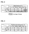
- the first map serves to variably control the charging current, wherein the battery temperature Ta indicated along the horizontal direction of the map, and the change in temperature dTa/dt indicated along the vertical direction are taken to define the first allowable charging current values that permit charging while suppressing the increase in battery temperature. Specifically, if the temperature of batteries 55 is high and the increase in temperature is high, then relatively low charging current (e.g., Ia35) is applied (lower right side of the map). If the temperature of the batteries 55 is high and the increase in temperature is low, then moderate level of charging current (e.g., Ia15) is applied (upper right side of the map).
- relatively low charging current e.g., Ia35
- moderate level of charging current e.g., Ia15
- a moderate level of charging current e.g., Ia31
- relatively high charging current e.g., Ia11
- each region within the first map provides as high a charging current as possible within a range whereby the battery temperature Ta does not exceed permissible temperatures.
- the lower current values in the left column of the first map may be preferably such that battery performance does not deteriorate.
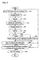
- the second map shown in FIG. 3, serves in the same manner as the first map to variably control the charging current, wherein the power source circuit temperature Tb indicated along the horizontal direction of the map, and the temperature difference dTb/dt indicated along the vertical direction are taken to define the second allowable charging current values that permit charging while suppressing the increase in temperature of power source circuit 32.
- relatively low charging current e.g., Ib35
- moderate level of charging current e.g., Ib15
- each region within the second map provides as high a charging current as possible within a range whereby the temperature of power source circuit 32 does not exceed permissible temperatures.
- control portion 36 preferably retrieves the first allowable charging current value for regulating the battery temperature Ta and the second allowable charging current value for regulating the power source circuit temperature Tb from the first and second maps having the allowable charging current values mapped therein, compares the two allowable charging current values, and selects the smaller of the two values. For example, when the battery temperature is Ta3 ⁇ Ta4, and the change in battery temperature (i.e., battery temperature-increase rate) is Xa1 ⁇ Xa2, then the current value provided in region Ia24 is the first allowable charging current value.
- the power source circuit temperature is Tb3 ⁇ Tb4
- the change in power source circuit temperature i.e., power source circuit temperature-increase rate
- the current value provided in region Ib24 is the second allowable charging current value. Then, the two values are compared, and the smaller of the two is output to charging-current control portion 34.
- control portion 36 may determine the completion of charging on the basis of change in the regions selected from within the first map. That is, the charging current varies as time passes, and consequently it is not possible to determine the completion of charging simply by observing the battery temperature, changes in the battery temperature values, battery voltage, or changes in the battery voltage values. For this reason, the change in the regions selected within the first map is used to determine the completion of charging.
- the temperature of batteries 55 and the change in the temperature-increase values leads varied regions to be selected as the first allowable charging current value. That is, when the temperature of batteries 55 is high, or the increase in battery temperature is high, a region having a relatively low charging current is selected (i.e., a region on the lower side and/or the right side of the first map shown in FIG. 2 is selected), whereupon the temperature of batteries 55, or the increase in battery temperature is reduced, and consequently a region on the upper side of the first map is then selected.
- control portion 36 may take measurements at predetermined intervals (e.g., at intervals of several hundred seconds). When the region selected is continuously (e.g., three times) one of the hatched regions shown in FIG.
- control portion 36 may determine that charging is complete, and terminate charging of batteries 55.
- control portion 36 detects the temperature Ta of batteries 55 (step S12).
- control portion 36 calculates the temperature-increase rate dTa/dt of batteries 55 by differentiating the detected temperature Ta (step S 14).
- control portion 36 retrieves the first map and read a first allowable charging current value Ia (step S 16).
- control portion 36 detects the temperature Tb of power source circuit 32 (step S 18), and calculates the temperature-increase rate dTb/dt of power source circuit 32 by differentiating the detected temperature Tb (step S20). Then, based upon the temperature Tb and the power source circuit temperature-increase rate dTb/dt, control portion 36 retrieves the second map and read a second allowable charging current value Ib (step S22).
- control portion 36 determines whether the second allowable charging current value Ib exceeds the first allowable charging current value Ia (step S24). In the case where the second allowable charging current value Ib exceeds the first allowable charging current value Ia (YES in step S24), control portion 36 selects the first allowable charging current value Ia as the optimal charging current value, and outputs a current command in accordance with this selection to charging-current control portion 34 (step S26). If the first allowable charging current value Ia exceeds the second allowable charging current value Ib (NO in step S24), control portion 36 selects the second allowable charging current value Ib as the optimal charging current value, and outputs a current command in accordance with this selection to charging-current control portion 34 (step S28).
- charging-current control portion 34 controls power source circuit 32 in a manner whereby the charging current dose not exceed the optimal current value (i.e., the smaller of the first allowable charging current value Ia and the second allowable charging current value Ib) indicated from the control portion 36.
- control portion 36 determines whether the first allowable charging current value have been selected within final stage of charging regions (i.e., the hatched regions Ia31, Ia32, Ia33, Ia34, Ia35 and Ia25 of the first map shown in FIG. 2) (step S30). In the case where the first allowable charging current value have not been selected from the final stage of charging regions (NO in step S30), the process returns to step S12, and the process is repeated from step S 12.
- control portion 36 determines whether there is a high frequency (i.e., probability) that the first allowable charging current value is selected from the final stage of charging region of the first map. For example, if the first allowable charging current values have been selected from the final stage of charging regions for three consecutive cycles, control portion 36 may determine that there is a high probability of a final stage of charging region being selected. If it is determined that there is a low probability that a final stage of charging region is selected (NO in step S32), the process returns to step S 12, and charging continues. If it is determined that there is a high probability that a final stage of charging region is selected (YES in step S32), charging is completed (step S34).
- a high frequency i.e., probability
- the probability of a final stage of charging region being selected is high when final stage of charging regions have been selected for three consecutive cycles. Nonetheless, a variety of other methods can be used to determine whether there is a high probability of a final stage of charging region being selected. For example, it can be determined that the probability is high when a final stage of charging region has been selected eight times in ten cycles.
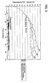
- FIG. 5 shows temperature transitions of power source circuit 32 when battery charger 10 consecutively charges six battery packs 50 by means of rapid charging performed in up to 30 minutes.
- FIG. 6 shows the charging periods during this charging.
- the case where control portion 36 of battery charger 10 controls using the first and second allowable charging current values Ia and Ib i.e., the case of the representative embodiment
- the case where the charging current value is fixed i.e., non-controlled case
- the case where the charging current value is fixed and the supply of charging current to the battery is stopped when the detected temperature of the power source circuit exceeds a specific temperature (i.e., the case of the conventional technique).
- a comparatively small power source circuit produces a large output (i.e., charging current), and charging efficiency is increased by reducing output by a suitable extent when the elements of the power source circuit grow hot. That is, even though the power source circuit is miniaturized, the charging current is output efficiently from the power source circuit, thus enabling rapid charging within a short period.
- the explanation was given using, as an example, the process for charging a nickel metal hydride battery.
- the battery charger and charging method of the present teachings can also be applied to the charging of other rechargeable batteries.
- the first map shown in FIG. 2 can be applied to the charging of a nickel cadmium battery by adjusting this map to suit the characteristics of nickel cadmium batteries.
Landscapes
- Engineering & Computer Science (AREA)
- Manufacturing & Machinery (AREA)
- Chemical & Material Sciences (AREA)
- Chemical Kinetics & Catalysis (AREA)
- Electrochemistry (AREA)
- General Chemical & Material Sciences (AREA)
- Power Engineering (AREA)
- Charge And Discharge Circuits For Batteries Or The Like (AREA)
- Secondary Cells (AREA)
Abstract
Description
It is explicitly stated that all features disclosed in the description and/or the claims are intended to be disclosed separately and independently from each other for the purpose of original disclosure as well as for the purpose of restricting the claimed invention independent of the compositions of the features in the embodiments and/or the claims. It is explicitly stated that all value ranges or indications of groups of entities disclose every possible intermediate value or intermediate entity for the purpose of original disclosure as well as for the purpose of restricting the claimed invention.
Claims (8)
- An apparatus comprising:a battery pack comprising battery cells and a first temperature sensor coupled to the battery cells, anda battery charger comprising a power source circuit arranged and constructed to supply charging current to the battery cells, a second temperature sensor coupled to the power source circuit and a processor arranged and constructed to (i) select charging current that will be supplied by the power source circuit to the battery cells based at least upon battery temperature from the first temperature sensor and power source circuit temperature from the second temperature sensor, and (ii) supply the selected charging current to the battery cells.
- An apparatus as in claim 1, wherein the processor is further arranged and constructed to calculate battery temperature increase rate based upon signals from the first temperature sensor and power source temperature increase rate based upon signals from the second temperature sensor, and select charging current that will be supplied by the power source circuit to the battery cells based further upon the calculated temperature increase rates.
- An apparatus as in claim 2, wherein the processor is further arranged and constructed to (1) select a first allowable charging current value based upon the battery temperature and the calculated battery temperature increase rate, (2) select a second allowable charging current value based upon the power source circuit temperature and the calculated power source circuit temperature increase rate, and (3) select the smaller of the first and second allowable charging current values as the charging current that will be supplied by the power source circuit to the battery cells.
- An apparatus as in claim 3, wherein the processor is further arranged and constructed to terminate the supply of charging current to the battery cells based upon a determination that relatively low first allowable charging currents have been repeatedly selected over series of intervals.
- A battery charger adapted to supply current to a removable battery pack comprising battery cells, a first temperature sensor coupled to the battery cells and a charging terminal, comprising:a power source circuit,a second temperature sensor coupled to the power source circuit,a first terminal arranged and constructed to couple to the first temperature sensor,a second terminal coupled to the power source circuit and arranged and constructed to conduct charging current via the charging terminal to the battery cells, anda controller coupled to the first terminal, the second temperature sensor and the power source circuit, the controller being arranged and constructed to select the amount of charging current supplied to the second terminal based at least upon battery temperature signal received from the first terminal and power source circuit temperature signal received from the second temperature sensor.
- A battery charger as in claim 5, the controller is further arranged and constructed to calculate battery temperature increase rate based upon signals received from the first terminal and power source temperature increase rate based upon signals from the second temperature sensor, and select charging current that will be supplied by the power source circuit to the second terminal based further upon the calculated temperature increase rates.
- A battery charger as in claim 6, wherein the controller is further arranged and constructed to (1) select a first allowable charging current value based upon the battery temperature and the calculated battery temperature increase rate, (2) select a second allowable charging current value based upon the power source circuit temperature and the calculated power source circuit temperature increase rate, and (3) select the smaller of the first and second allowable charging current as the charging current that will be supplied by the power source circuit to the second terminal.
- A battery charger as in claim 7, wherein the controller is further arranged and constructed to terminate the supply of charging current to the second terminal based upon a determination that relatively low first allowable charging currents have been repeatedly selected over series of intervals.
Applications Claiming Priority (2)
| Application Number | Priority Date | Filing Date | Title |
|---|---|---|---|
| JP2002371423A JP3936286B2 (en) | 2002-12-24 | 2002-12-24 | Charging apparatus and charging method |
| JP2002371423 | 2002-12-24 |
Publications (3)
| Publication Number | Publication Date |
|---|---|
| EP1434328A2 true EP1434328A2 (en) | 2004-06-30 |
| EP1434328A3 EP1434328A3 (en) | 2005-05-18 |
| EP1434328B1 EP1434328B1 (en) | 2010-09-29 |
Family
ID=32463497
Family Applications (1)
| Application Number | Title | Priority Date | Filing Date |
|---|---|---|---|
| EP03029443A Expired - Lifetime EP1434328B1 (en) | 2002-12-24 | 2003-12-19 | Battery charger |
Country Status (5)
| Country | Link |
|---|---|
| US (1) | US7106027B2 (en) |
| EP (1) | EP1434328B1 (en) |
| JP (1) | JP3936286B2 (en) |
| CN (1) | CN100338842C (en) |
| DE (1) | DE60334361D1 (en) |
Cited By (3)
| Publication number | Priority date | Publication date | Assignee | Title |
|---|---|---|---|---|
| WO2006135838A3 (en) * | 2005-06-10 | 2007-08-09 | Agere Systems Inc | Multi-threshold charging of a rechargeable battery |
| US7830101B2 (en) | 2005-06-10 | 2010-11-09 | Agere Systems, Inc. | Regulation of electrical current through a resistive load |
| EP1850443A3 (en) * | 2006-04-28 | 2014-03-05 | Hitachi Koki Co., Ltd. | Charging device for battery |
Families Citing this family (27)
| Publication number | Priority date | Publication date | Assignee | Title |
|---|---|---|---|---|
| JP2006203980A (en) | 2005-01-18 | 2006-08-03 | Nec Corp | Mobile device |
| JP2007020245A (en) * | 2005-07-05 | 2007-01-25 | Ricoh Co Ltd | Charging circuit and semiconductor device provided with the charging circuit |
| US7710078B2 (en) * | 2006-01-05 | 2010-05-04 | Pine Valley Investments, Inc. | Battery charger with temperature compensation |
| EP1882997A1 (en) * | 2006-07-27 | 2008-01-30 | STMicroelectronics Limited | Battery charger with temperature-dependent power control |
| JP4660523B2 (en) * | 2007-09-19 | 2011-03-30 | レノボ・シンガポール・プライベート・リミテッド | Charging system that controls charging at the surface temperature of the battery cell |
| WO2009046533A1 (en) * | 2007-10-11 | 2009-04-16 | Icp Global Technologies Inc. | Autonomous hybrid renewable energy controller |
| JP5309641B2 (en) * | 2008-03-24 | 2013-10-09 | ミツミ電機株式会社 | Semiconductor integrated circuit for charge control |
| KR101282137B1 (en) * | 2008-08-11 | 2013-07-04 | 삼성전자주식회사 | Portable device and method of controlling thereof |
| US20100190052A1 (en) * | 2009-01-27 | 2010-07-29 | Umesh Rajani | Battery pack with high and low current discharge terminals |
| JP5554622B2 (en) * | 2010-04-21 | 2014-07-23 | 株式会社マキタ | Electric tool equipment |
| JP5524694B2 (en) * | 2010-04-21 | 2014-06-18 | 株式会社マキタ | Device for estimating calorific value of power tool battery and power tool device |
| US8836287B2 (en) * | 2011-05-03 | 2014-09-16 | Apple Inc. | Time-domain multiplexing of power and data |
| US9197096B2 (en) | 2012-01-19 | 2015-11-24 | Apple Inc. | Charging techniques for solid-state batteries in portable electronic devices |
| JP5961440B2 (en) * | 2012-05-01 | 2016-08-02 | 株式会社マキタ | Electrical equipment |
| US9153992B2 (en) * | 2012-12-12 | 2015-10-06 | Richtek Technology Corporation | High-temperature resistant power bank circuit |
| US8907631B1 (en) | 2013-07-31 | 2014-12-09 | Qnovo Inc. | Adaptive charging technique and circuitry for a battery/cell using multiple charge circuits and temperature data |
| EP3249776A1 (en) * | 2015-01-14 | 2017-11-29 | Black & Decker Inc. | Battery charger and method of charging a battery |
| JP6767198B2 (en) * | 2015-11-30 | 2020-10-14 | 株式会社マキタ | Battery device and charging device |
| EP3255721B1 (en) * | 2016-06-08 | 2020-04-29 | Robert Bosch GmbH | Method for controlling a temperature of a battery cell |
| US10879715B2 (en) * | 2017-03-08 | 2020-12-29 | Mediatek Inc. | Method for improving temperature management of battery pack |
| CN109148985A (en) * | 2017-06-15 | 2019-01-04 | 苏州宝时得电动工具有限公司 | A kind of battery pack charging method and device |
| WO2019039114A1 (en) * | 2017-08-23 | 2019-02-28 | ソニー株式会社 | Electricity storage control device, electricity storage control method, and electricity storage system |
| US11289933B2 (en) * | 2019-05-15 | 2022-03-29 | Ahmad Eivaz | Battery charging enclosure |
| US20220407341A1 (en) * | 2019-11-01 | 2022-12-22 | The Noco Company | Battery charging device having a temperature sensor for providing temperature compensation during charging, and method of measuring depleted or discharged battery temperature for compensating charging of a battery charging device |
| EP4183023A4 (en) * | 2020-07-20 | 2024-09-04 | Milwaukee Electric Tool Corporation | SYSTEMS, METHODS AND DEVICES FOR INCREASING THE CHARGING RATE OF LITHIUM-BASED BATTERY PACKS |
| CN114132203B (en) * | 2020-09-04 | 2023-11-14 | 南京国电南思科技发展股份有限公司 | Charging pile control system based on intelligent temperature and humidity adjustment |
| US12466047B2 (en) * | 2023-03-22 | 2025-11-11 | Milwaukee Electric Tool Corporation | Power tools including a plurality of temperature sensors |
Family Cites Families (20)
| Publication number | Priority date | Publication date | Assignee | Title |
|---|---|---|---|---|
| US5889386A (en) * | 1982-06-07 | 1999-03-30 | Intermec Technology Corporation | Battery conditioning system having communication with battery parameter memory means in conjunction with battery conditioning |
| JPH06284591A (en) * | 1993-03-31 | 1994-10-07 | Mitsubishi Electric Corp | Charger |
| JPH07222370A (en) * | 1994-01-28 | 1995-08-18 | Sanyo Electric Co Ltd | Charger with temperature sensor |
| JP3902253B2 (en) * | 1994-12-26 | 2007-04-04 | ヤマハ発動機株式会社 | Rechargeable battery charging method |
| JP3509382B2 (en) * | 1995-04-27 | 2004-03-22 | 日産自動車株式会社 | Charge control system |
| JPH10234140A (en) * | 1997-02-19 | 1998-09-02 | Matsushita Electric Ind Co Ltd | Battery state detector |
| JP3378189B2 (en) * | 1998-02-28 | 2003-02-17 | 株式会社マキタ | Charging device and charging method |
| EP0964497B1 (en) * | 1998-06-09 | 2010-10-13 | Makita Corporation | Battery charger |
| JP3390667B2 (en) | 1998-06-09 | 2003-03-24 | 株式会社マキタ | Charging device |
| JP3506916B2 (en) * | 1998-07-03 | 2004-03-15 | 株式会社マキタ | Charging device |
| JP3265570B2 (en) * | 1998-07-07 | 2002-03-11 | 日本電気株式会社 | Charging circuit |
| JP3495637B2 (en) | 1999-03-26 | 2004-02-09 | 株式会社マキタ | Charging device and charging system |
| US6476584B2 (en) * | 1999-03-25 | 2002-11-05 | Makita Corporation | Battery charger and battery charging method |
| JP3495636B2 (en) * | 1999-03-25 | 2004-02-09 | 株式会社マキタ | Charging device |
| JP3652191B2 (en) * | 1999-11-10 | 2005-05-25 | 株式会社マキタ | Charger |
| EP1100172A3 (en) | 1999-11-10 | 2004-10-13 | Makita Corporation | Battery charging device |
| JP3581064B2 (en) | 1999-11-10 | 2004-10-27 | 株式会社マキタ | Charging device |
| JP3638483B2 (en) * | 1999-11-10 | 2005-04-13 | 株式会社マキタ | Charging device and charging method |
| JP2001211559A (en) | 2000-01-24 | 2001-08-03 | Makita Corp | Charging device |
| JP3778262B2 (en) * | 2000-12-21 | 2006-05-24 | 株式会社マキタ | Charging method and battery pack |
-
2002
- 2002-12-24 JP JP2002371423A patent/JP3936286B2/en not_active Expired - Lifetime
-
2003
- 2003-12-19 DE DE60334361T patent/DE60334361D1/en not_active Expired - Lifetime
- 2003-12-19 EP EP03029443A patent/EP1434328B1/en not_active Expired - Lifetime
- 2003-12-22 CN CNB2003101131153A patent/CN100338842C/en not_active Expired - Lifetime
- 2003-12-23 US US10/744,924 patent/US7106027B2/en not_active Expired - Lifetime
Cited By (4)
| Publication number | Priority date | Publication date | Assignee | Title |
|---|---|---|---|---|
| WO2006135838A3 (en) * | 2005-06-10 | 2007-08-09 | Agere Systems Inc | Multi-threshold charging of a rechargeable battery |
| US7737665B2 (en) | 2005-06-10 | 2010-06-15 | Agere Systems Inc. | Multi-threshold charging of a rechargeable battery |
| US7830101B2 (en) | 2005-06-10 | 2010-11-09 | Agere Systems, Inc. | Regulation of electrical current through a resistive load |
| EP1850443A3 (en) * | 2006-04-28 | 2014-03-05 | Hitachi Koki Co., Ltd. | Charging device for battery |
Also Published As
| Publication number | Publication date |
|---|---|
| DE60334361D1 (en) | 2010-11-11 |
| EP1434328A3 (en) | 2005-05-18 |
| US7106027B2 (en) | 2006-09-12 |
| US20040135553A1 (en) | 2004-07-15 |
| CN1510814A (en) | 2004-07-07 |
| JP3936286B2 (en) | 2007-06-27 |
| EP1434328B1 (en) | 2010-09-29 |
| CN100338842C (en) | 2007-09-19 |
| JP2004208349A (en) | 2004-07-22 |
Similar Documents
| Publication | Publication Date | Title |
|---|---|---|
| EP1434328B1 (en) | Battery charger | |
| EP1439624B1 (en) | Battery charger | |
| US6476584B2 (en) | Battery charger and battery charging method | |
| US6603288B2 (en) | Battery chargers and charging methods | |
| EP1681741B1 (en) | Multi-series connection type battery cell pack | |
| USRE39691E1 (en) | Battery charger and battery charging method | |
| US6504341B2 (en) | Method and apparatus for identifying and charging batteries | |
| US5539297A (en) | Charging device for charging a plurality of batteries based on parameter priority | |
| CA2042100C (en) | Battery charging system | |
| US20080238361A1 (en) | Adaptive charger device and method | |
| US9190863B2 (en) | Apparatus and method for charging battery by lowering charge power in phase | |
| US20080238357A1 (en) | Ultra fast battery charger with battery sensing | |
| JP4691140B2 (en) | Charge / discharge system and portable computer | |
| JP2006197727A (en) | Battery current limit control method | |
| JP2010521948A (en) | Adaptive charging apparatus and method | |
| US6225786B1 (en) | Battery charger | |
| US20080174263A1 (en) | Battery charger for different capacity cells | |
| US7656130B2 (en) | Battery charger | |
| JP3629791B2 (en) | Charge control device for battery pack | |
| US20060238166A1 (en) | Charge control device | |
| JP5165405B2 (en) | Charge control circuit, battery pack, and charging system | |
| EP0747986B1 (en) | Method and device for judging secondary cell to be connected to charger | |
| CN114640146A (en) | Accumulator battery | |
| JP3390666B2 (en) | Charging device | |
| KR102548137B1 (en) | Battery Management Method and Battery Management System |
Legal Events
| Date | Code | Title | Description |
|---|---|---|---|
| PUAI | Public reference made under article 153(3) epc to a published international application that has entered the european phase |
Free format text: ORIGINAL CODE: 0009012 |
|
| AK | Designated contracting states |
Kind code of ref document: A2 Designated state(s): AT BE BG CH CY CZ DE DK EE ES FI FR GB GR HU IE IT LI LU MC NL PT RO SE SI SK TR |
|
| AX | Request for extension of the european patent |
Extension state: AL LT LV MK |
|
| PUAL | Search report despatched |
Free format text: ORIGINAL CODE: 0009013 |
|
| AK | Designated contracting states |
Kind code of ref document: A3 Designated state(s): AT BE BG CH CY CZ DE DK EE ES FI FR GB GR HU IE IT LI LU MC NL PT RO SE SI SK TR |
|
| AX | Request for extension of the european patent |
Extension state: AL LT LV MK |
|
| 17P | Request for examination filed |
Effective date: 20050615 |
|
| AKX | Designation fees paid |
Designated state(s): DE FR GB |
|
| 17Q | First examination report despatched |
Effective date: 20050719 |
|
| GRAP | Despatch of communication of intention to grant a patent |
Free format text: ORIGINAL CODE: EPIDOSNIGR1 |
|
| GRAS | Grant fee paid |
Free format text: ORIGINAL CODE: EPIDOSNIGR3 |
|
| GRAA | (expected) grant |
Free format text: ORIGINAL CODE: 0009210 |
|
| AK | Designated contracting states |
Kind code of ref document: B1 Designated state(s): DE FR GB |
|
| REG | Reference to a national code |
Ref country code: GB Ref legal event code: FG4D |
|
| REF | Corresponds to: |
Ref document number: 60334361 Country of ref document: DE Date of ref document: 20101111 Kind code of ref document: P |
|
| PLBE | No opposition filed within time limit |
Free format text: ORIGINAL CODE: 0009261 |
|
| STAA | Information on the status of an ep patent application or granted ep patent |
Free format text: STATUS: NO OPPOSITION FILED WITHIN TIME LIMIT |
|
| 26N | No opposition filed |
Effective date: 20110630 |
|
| REG | Reference to a national code |
Ref country code: DE Ref legal event code: R097 Ref document number: 60334361 Country of ref document: DE Effective date: 20110630 |
|
| REG | Reference to a national code |
Ref country code: FR Ref legal event code: PLFP Year of fee payment: 13 |
|
| REG | Reference to a national code |
Ref country code: FR Ref legal event code: PLFP Year of fee payment: 14 |
|
| REG | Reference to a national code |
Ref country code: FR Ref legal event code: PLFP Year of fee payment: 15 |
|
| PGFP | Annual fee paid to national office [announced via postgrant information from national office to epo] |
Ref country code: GB Payment date: 20221027 Year of fee payment: 20 Ref country code: FR Payment date: 20221110 Year of fee payment: 20 Ref country code: DE Payment date: 20220622 Year of fee payment: 20 |
|
| REG | Reference to a national code |
Ref country code: DE Ref legal event code: R071 Ref document number: 60334361 Country of ref document: DE |
|
| REG | Reference to a national code |
Ref country code: GB Ref legal event code: PE20 Expiry date: 20231218 |
|
| PG25 | Lapsed in a contracting state [announced via postgrant information from national office to epo] |
Ref country code: GB Free format text: LAPSE BECAUSE OF EXPIRATION OF PROTECTION Effective date: 20231218 |
|
| PG25 | Lapsed in a contracting state [announced via postgrant information from national office to epo] |
Ref country code: GB Free format text: LAPSE BECAUSE OF EXPIRATION OF PROTECTION Effective date: 20231218 |